QX 870 Industrial Raster Scanner Quick Start Guide Qx870quickstartguide
2009-10-07
: Microscan Qx870Quickstartguide qx870quickstartguide 06e7034e-039d-4d46-953c-9e09dabba0ec _att
Open the PDF directly: View PDF ![]() .
.
Page Count: 2
Copyright ©2009 Microscan Systems, Inc.
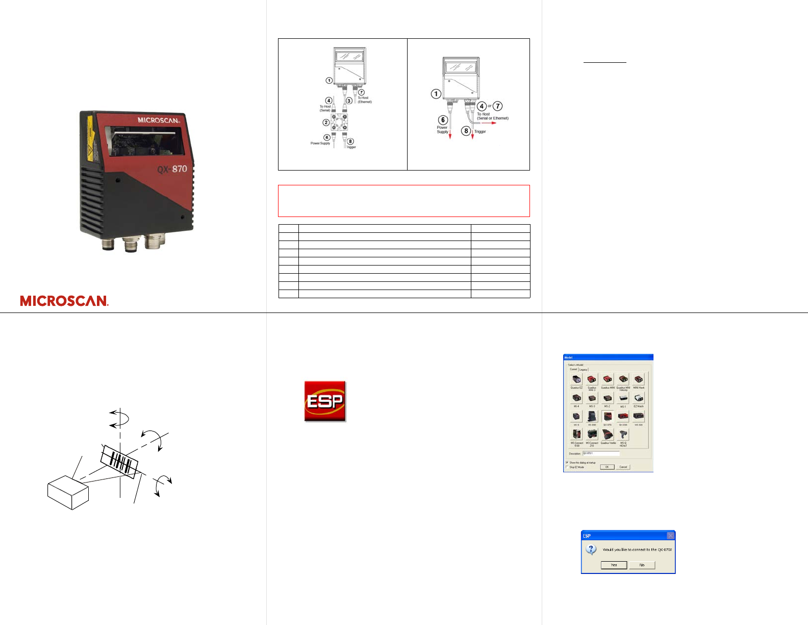
Step 2 — Connect the System
Important: When connecting Ultra-Lock cordsets to the QX-870
and QX-1, align the pins first and then push the connector into
place. Do not twist the connectors, as this will bend the pins.
Important: Do not attempt to power more than four scanners with
a single power supply in a daisy chain configuration. Add a QX-1
and one power supply for every four additional scanners in the
daisy chain.
RS-232
1. Connect the Serial Communication Cable from “A” on the
QX-870 to “2” on the QX-1.
2. Connect the host cable from “1” on the QX-1 to the host computer.
3. Connect the photo sensor to “T” on the QX-1.
4. Connect the power supply to “3” on the QX-1.
5. Plug in the power supply.
Ethernet
1. Connect the Ethernet Cable from “B” on the QX-870 to the
network.
2. Connect the power supply to “A” on the QX-870.
3. Plug in the power supply.
Step 1 — Check Hardware
Item Description Part Number
1
QX-870 Industrial Raster Scanner
FIS-0870-XXXXG
2
QX-1 Interface Device
98-000103-01
3
QX Cordset, Common, M12 12-pin Plug to M12 12-pin Socket, 1 m
61-000162-01
4
QX Cordset, Host, Serial, M12 12-pin Plug to DB9, 1 m
61-000152-01
5
QX Cordset, Host, Serial, M12 12-pin Socket to DB9, 1 m
61-000153-01
6
QX Power Supply, M12 12-pin Socket, 1.3 m
97-000003-01
7
QX Cordset, Host, Ethernet, M12 8-pin Plug to RJ45, 1 m
61-000160-01
8
QX Photo Sensor, M12 4-pin Plug, NPN, Dark On, 2 m
99-000020-02
Note:
Additional cordsets and accessories are available in the Microscan Product Pricing Catalog.
Caution: Be sure that all connections are secure BEFORE applying power
to the system. Always power down BEFORE disconnecting any cables.
Hardware Required
Standalone (with QX-1) Standalone (without QX-1)
Quick Start Guide
QX-870 Industrial
Raster Scanner
P/N 83-110870 Rev B
Step 3 — Position Scanner
1. Place a test symbol in a location with as little ambient light
as possible.
2. Position the scanner at the focal distance used in your application.
3. Align the test symbol with the scanner’s field of view.
4. Tip the scanner relative to the test symbol to avoid glare
from specular reflection.
Pitch
axis
Bar code
label Tilt
axis
axis
Scan line
Scanner
Pitch
Tilt
Skew
Symbol
Scanner
Maximum
skew, tilt,
and pitch:
±30°
Step 4 — Install ESP
ESP Software can be found on the Microscan Tools CD that is
packaged with the QX-870.
1. Follow the prompts to install ESP from the CD.
2. Click on the ESP icon to run the program.
Note: ESP can also be installed from the Download Center at
www.microscan.com.
Refer to the QX-870 Industrial Raster Scanner User’s Manual for
detailed information about using ESP to configure the QX-870.
Step 5 —
Select Model
When you start ESP, the model menu will appear:
1. Click the button showing the QX-870.
2. Click OK.
Note: You can also simply double-click the button showing
your scanner to make your selection.
3. Click Yes when this dialog appears:
Note: If you need to select another model later, click the
Switch Model button near the top of the screen or use
Model > New Model in the menu toolbar.
Copyright ©2009 Microscan Systems, Inc.
Step 6 — Connect
RS-232
To connect using the Connection Wizard:
•
Click
Connect
on the menu toolbar, and then select
Connection
Wizard.
• Select RS-232.
• Configure RS-232 settings as required by the application,
and click Connect.
• When a connection is established, the green indicator in the
status bar at the bottom right of the screen will be visible:
Important:
The scanner is in
Continuous Read Mode
by
default. For best connection results, be sure that no decodable
symbols are within the scanner’s field of view while attempting
to connect.
Step 7 — Test Read Rate
Read Rate indicates the number or percentage of successful
decodes per second achieved by the scanner.
1. Click the Test button in ESP’s EZ Mode to start the Read
Rate test.
Symbol data and read rate percentage information should
appear in the Symbol Information table. The Read Rate
LEDs on the side of the QX-870 will indicate the percentage
of successful decodes per second.
2. Click Stop to end the Read Rate test.
Note: Read Rate can also be tested using the Read Rate
interface in Utilities.
Refer to the QX-870 Industrial Raster Scanner User’s
Manual
for information about how to test read rate using serial
commands
or the scanner’s EZ button.
Step 6 — Connect (cont.)
Ethernet TCP/IP
To connect using the Connection Wizard:
• Click Connect on the menu toolbar, and then select Connection
Wizard.
• Select Ethernet.
• Configure Ethernet settings as required by the application, and
click Connect.
• When a connection is established, the green indicator in the status
bar at the bottom right of the screen will be visible.
Important:
The scanner is in
Continuous Read Mode
by default.
For best connection results, be sure that no decodable symbols are
within the scanner’s field of view while attempting to connect.
Step 8 — Configure the Scanner
Click the
App Mode
button to make configuration changes to the scanner.
The following modes are accessible by clicking the buttons at the top
of the screen:
• Click the EZ Mode button to return to EZ Mode.
• Click the Autoconnect button to establish communications.
• Click the Send/Recv button to send or receive commands.
• Click the Switch Model button to open the model menu, or to
return to the previous model.
• Click the Parameters button to show the tabbed tree control views.
• Click the
Setup
button to show the tabbed interface views.
• Click the Terminal button to display decoded symbol data and to
send serial commands.
• Click the Utilities button to access Read Rate, Counters, Device
Control, Differences from Default, Master Database, Digital Bar
Code, and Firmware.
For further details, see Microscan ESP Help in the dropdown
Help menu.
Step 6 — Connect (cont.)
Ethernet TCP/IP (cont.)
When the QX-870 is connected, incoming symbol data can be
displayed in the Terminal, as shown below.
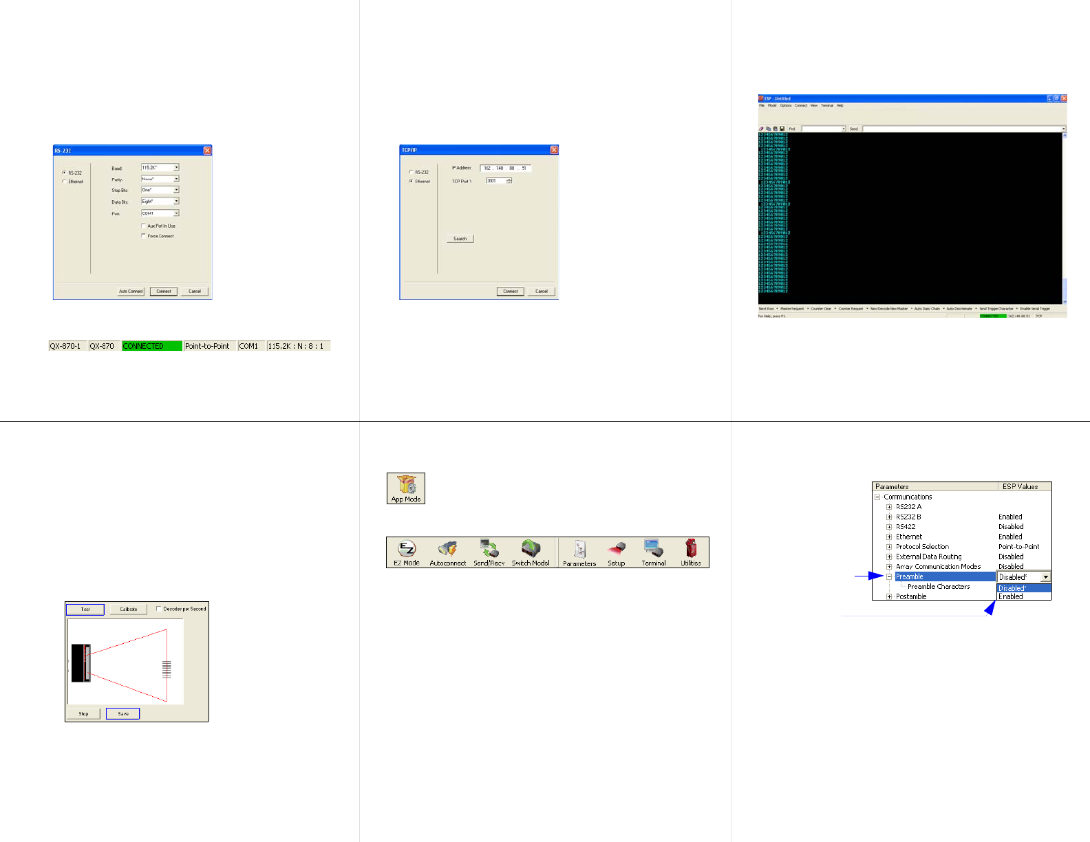
Step 9 — Save Changes
To make changes to configuration settings in the tree controls:
Saving Options
•Send, No Save. Changes will be lost when power is re-applied
to the scanner.
•Send and Save. This activates all changes in current memory
and saves to the scanner for power-on.
1. Left-click on the
+ to expand the
desired tree.
2. Double-click on
the desired
parameter and
click once in the
selection box to
view options.
5. Right-click on the
open screen and
select Save to
Reader to implement
the command in the
scanner.
4. Left-click on the
open screen to
complete your
selection.
3. Place your cursor
in the selection
box, scroll down to
the setting you
want to change,
and click once on
the setting.
