Microsoft CK1W Bluetooth Wireless Car Kit User Manual CK IW IG en1

Microsoft Mobile Oy Bluetooth Wireless Car Kit CK IW IG en1
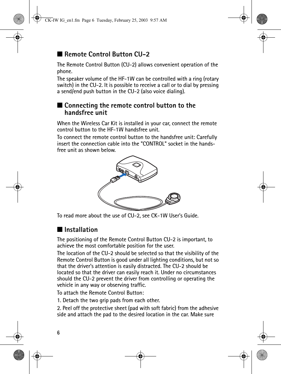
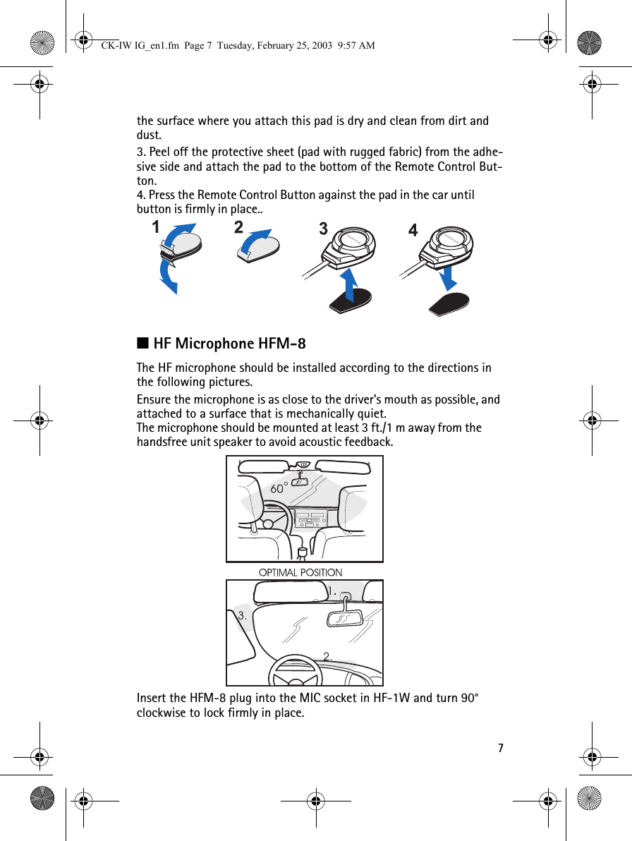
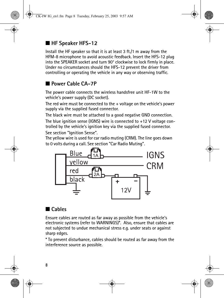
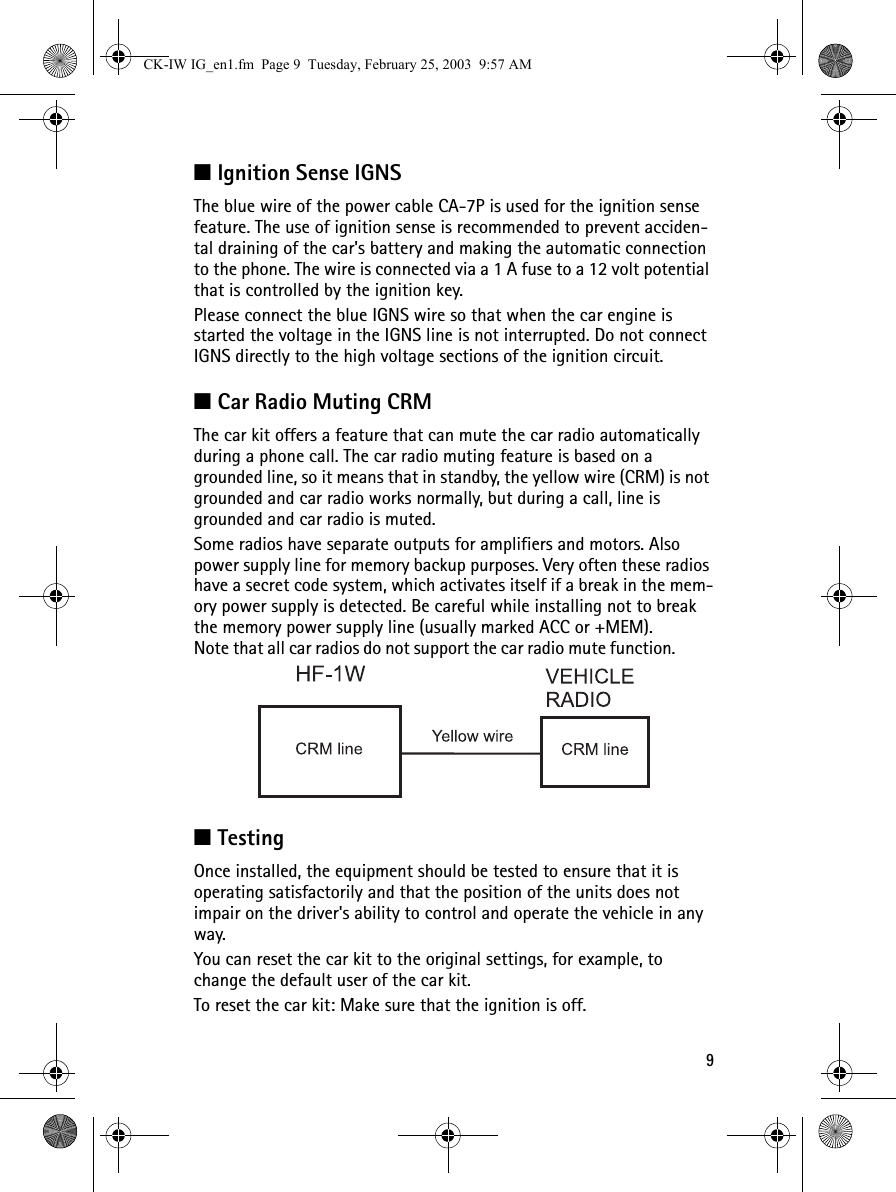
Contents

installataion guide

2■IntroductionThis installation guide has been prepared to provide the basic information necessary to install the car kit. This guide is not intended to be definitive, because different types and models of vehicles will require different installation work. The information given is for general guidance only.The terms of warranty demand that this car kit be installed by an expe-rienced installer and only genuine Nokia parts are used. An end user should never attempt to install this car kit without professional assis-tance as the installation requires special tools and knowledge.All installations should take into account any special requirements of the customer. However, should the customer require an installation that is illegal or unsafe these facts must be pointed out to the cus-tomer and a policy of non-compliance adopted.Please refer to the phone's User's Guide for instructions on the phone's operation, care and maintenance, including important safety informa-tion.Copyright © Nokia 2003. All rights reserved.Note: Read the warnings below before beginning the installation pro-cedure.Nokia Corporation 935XXXX issue 1CK-IW IG_en1.fm  Page 2  Tuesday, February 25, 2003  9:57 AM
3■WARNINGS1. ENSURE THAT THE VEHICLE'S BATTERY IS DISCONNECTED BEFORE YOU START THE INSTALLATION PROCEDURE, AND THAT IT REMAINS DISCONNECTED DURING THE PROCEDURE.2. DO NOT SMOKE OR USE OPEN FLAMES WHEN WORKING NEAR THE VEHICLE'S FUEL SYSTEM.3. ENSURE THAT THE VEHICLE'S ELECTRICAL CABLES, HYDRAULIC LINES, FUEL LINES, AND SAFETY EQUIPMENT ARE NOT DAMAGED DURING INSTALLATION.4. ENSURE THAT NORMAL CONTROL AND OPERATION OF THE VEHICLE IS NOT IMPAIRED BY THE INSTALLATION, PARTICULARLY THE BRAKES AND STEERING. ENSURE THAT AIRBAG  OPERATION IS NOT OBSTRUCTED.5. ELECTRONIC AND OTHER SOPHISTICATED SYSTEMS (e.g. SPEED CONTROL, ABS ANTI-LOCK BRAKE, FUEL INJECTION-, NAVIGATION-, AND AIR-BAG SYSTEMS) ARE RELATIVELY IMMUNE TO MALFUNCTION CAUSED BY NEARBY RADIO TRANSMISSIONS. HOW EVER, SHOULD YOU EXPERIENCE FALSE OPERATION OF THESE SYSTEMS OR ARE IN ANY DOUBT WHATSOEVER AS TO THEIR FUNCTIONALITY, PLEASE CONSULT THE VEHICLE'S DEALER.6. THE CAR KIT IS SUITABLE FOR USE ONLY IN VEHICLES WITH A 12 V NEGATIVE GROUNDING. USE ON OTHER SUPPLY VOLTAGES OR ALTERNATIVE POLARITY WILL DAMAGE THE EQUIPMENT.7. THE PHONE SHOULD NOT BE LEFT SWITCHED ON FOR EXTENDED PERIODS WITHOUT RUNNING THE VEHICLE'S ENGINE. FAILURE TO COMPLY COULD DRAIN THE VEHICLE'S BATTERY.CK-IW IG_en1.fm  Page 3  Tuesday, February 25, 2003  9:57 AM
4■UnpackingCarefully unpack the equipment and ensure that the followingitems are present.Wireless Hands Free Unit HF-1WRemote Control Button CU-2Power Cable CA-7PMounting Plate HH-1HF Microphone HFM-8HF Speaker HFS-12CK-IW IG_en1.fm  Page 4  Tuesday, February 25, 2003  9:57 AM
5■Wireless HF Unit HF-1W1. Speaker2. Mic3. Remote4. DC5. Internal bluetooth antennaThe HF-1W is used in a fixed car installation and it offers a wireless handsfree function and a wireless connection to compatible external devices.The HF-1W unit is attached to the vehicle interior using the mounting plate HH-1. HF-1W is secured to HH-1 with a screw (included with HH-1). Power is supplied to DC socket from the vehicle's battery via the power cable CA-7P.The HF microphone HFM-8, connects to the MIC socket. And the HF speaker HFS-12, connects to the SPEAKER socket.The HF-1W is always connected to a car battery. To save the car battery the HF-1W goes to a sleep mode. Sleep mode is activated when the ignition is turned off and there is no active call.■InstallationAfter tightening the HH-1 screws, secure HF-1W installation to the HH-1 mounting plate with the screw going through HF-1W. The Nokia logo lid is placed on the HF-1W to cover the recess.Do not install the HF-1W unit in a metal casing (or similar location) that can prevent the unit from transmitting radio frequencies. Aim the internal Bluetooth antenna (see picture) towards the user (Bluetooth phone).■Mounting Plate HH-1HH-1 is a fixed position mounting plate. It is used to attach Wireless HF Unit (HF-1W) to the vehicle.CK-IW IG_en1.fm  Page 5  Tuesday, February 25, 2003  9:57 AM
6■Remote Control Button CU-2The Remote Control Button (CU-2) allows convenient operation of the phone. The speaker volume of the HF-1W can be controlled with a ring (rotary switch) in the CU-2. It is possible to receive a call or to dial by pressing a send/end push button in the CU-2 (also voice dialing).■Connecting the remote control button to the handsfree unitWhen the Wireless Car Kit is installed in your car, connect the remote control button to the HF-1W handsfree unit.To connect the remote control button to the handsfree unit: Carefully insert the connection cable into the "CONTROL" socket in the hands-free unit as shown below.To read more about the use of CU-2, see CK-1W User's Guide.■InstallationThe positioning of the Remote Control Button CU-2 is important, to achieve the most comfortable position for the user. The location of the CU-2 should be selected so that the visibility of the Remote Control Button is good under all lighting conditions, but not so that the driver's attention is easily distracted. The CU-2 should be located so that the driver can easily reach it. Under no circumstances should the CU-2 prevent the driver from controlling or operating the vehicle in any way or observing traffic.To attach the Remote Control Button:1. Detach the two grip pads from each other.2. Peel off the protective sheet (pad with soft fabric) from the adhesive side and attach the pad to the desired location in the car. Make sure CK-IW IG_en1.fm  Page 6  Tuesday, February 25, 2003  9:57 AM
7the surface where you attach this pad is dry and clean from dirt and dust.3. Peel off the protective sheet (pad with rugged fabric) from the adhe-sive side and attach the pad to the bottom of the Remote Control But-ton.4. Press the Remote Control Button against the pad in the car until button is firmly in place..■HF Microphone HFM-8The HF microphone should be installed according to the directions in the following pictures. Ensure the microphone is as close to the driver's mouth as possible, and attached to a surface that is mechanically quiet.The microphone should be mounted at least 3 ft./1 m away from the handsfree unit speaker to avoid acoustic feedback.Insert the HFM-8 plug into the MIC socket in HF-1W and turn 90° clockwise to lock firmly in place.CK-IW IG_en1.fm  Page 7  Tuesday, February 25, 2003  9:57 AM
8■HF Speaker HFS-12Install the HF speaker so that it is at least 3 ft./1 m away from the HFM-8 microphone to avoid acoustic feedback. Insert the HFS-12 plug into the SPEAKER socket and turn 90° clockwise to lock firmly in place. Under no circumstances should the HFS-12 prevent the driver from controlling or operating the vehicle in any way or observing traffic.■Power Cable CA-7PThe power cable connects the wireless handsfree unit HF-1W to the vehicle's power supply (DC socket).The red wire must be connected to the + voltage on the vehicle's power supply via the supplied fused connector. The black wire must be attached to a good negative GND connection. The blue ignition sense (IGNS) wire is connected to +12 V voltage con-trolled by the vehicle's ignition key via the supplied fused connector. See section "Ignition Sense". The yellow wire is used for car radio muting (CRM). The line goes down to 0 volts during a call. See section "Car Radio Muting".■CablesEnsure cables are routed as far away as possible from the vehicle's electronic systems (refer to WARNINGS)*.  Also, ensure that cables are not subjected to undue mechanical stress e.g. under seats or against sharp edges.* To prevent disturbance, cables should be routed as far away from the interference source as possible.CK-IW IG_en1.fm  Page 8  Tuesday, February 25, 2003  9:57 AM
9■Ignition Sense IGNSThe blue wire of the power cable CA-7P is used for the ignition sense feature. The use of ignition sense is recommended to prevent acciden-tal draining of the car's battery and making the automatic connection to the phone. The wire is connected via a 1 A fuse to a 12 volt potential that is controlled by the ignition key. Please connect the blue IGNS wire so that when the car engine is started the voltage in the IGNS line is not interrupted. Do not connect IGNS directly to the high voltage sections of the ignition circuit.■Car Radio Muting CRMThe car kit offers a feature that can mute the car radio automatically during a phone call. The car radio muting feature is based on a grounded line, so it means that in standby, the yellow wire (CRM) is not grounded and car radio works normally, but during a call, line is grounded and car radio is muted.Some radios have separate outputs for amplifiers and motors. Also power supply line for memory backup purposes. Very often these radios have a secret code system, which activates itself if a break in the mem-ory power supply is detected. Be careful while installing not to break the memory power supply line (usually marked ACC or +MEM).Note that all car radios do not support the car radio mute function.■TestingOnce installed, the equipment should be tested to ensure that it is operating satisfactorily and that the position of the units does not impair on the driver's ability to control and operate the vehicle in any way.You can reset the car kit to the original settings, for example, to change the default user of the car kit.To reset the car kit: Make sure that the ignition is off. CK-IW IG_en1.fm  Page 9  Tuesday, February 25, 2003  9:57 AM
10Press and hold the button until the indicator light starts to blink. When the blinking stops the car kit has been reset. For operating information refer to the CK-1W User's Guide or User's Guide supplied with the phone.CK-IW IG_en1.fm  Page 10  Tuesday, February 25, 2003  9:57 AM

Navigation menu