Microtek MRS-600V48U Image Scanner User Manual sm3800new3a
Microtek International Inc Image Scanner sm3800new3a
Microtek >
users manual
12 3 45
Documentation
PC MAC
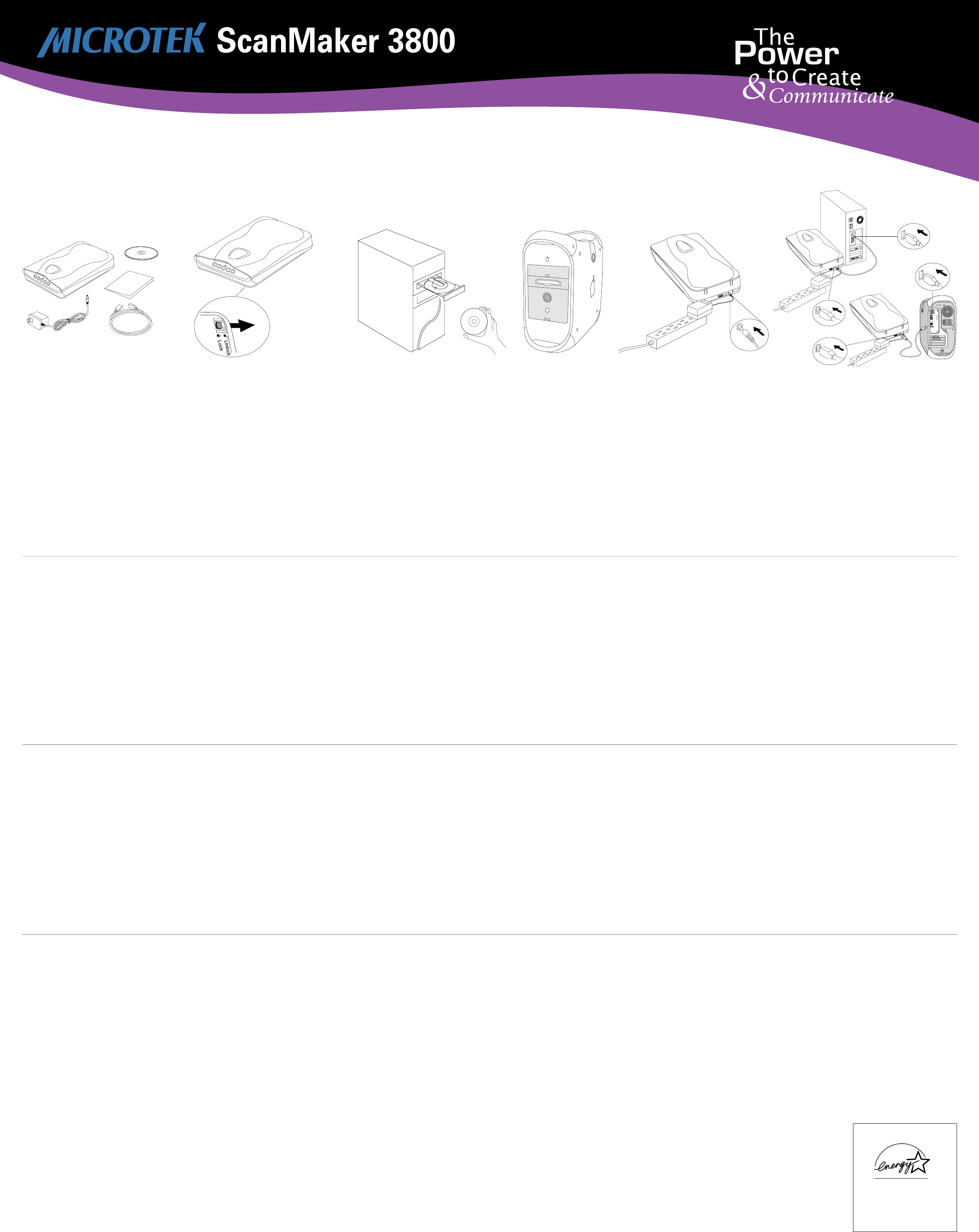
Unpack the scanner and check
components
Unpack the scanner package and check for major
components. Please refer to the enclosed Packing
List for a detailed listing of your components.
• Microtek Scanner
• Power Adapter
• USB (Universal Serial Bus) Cable
• Documentation
• Microtek CD-ROM
Install the software
PC:
A. Place the Microtek CD-ROM into the
CD-ROM drive.
B. Follow the on-screen instructions to install the
driver and software. Do
not
turn off your
computer until all the software has been
installed.
NOTE: If the Microtek Software Installer
screen does not come up automatically,
double-click the following in succession: “My
Computer” on your Windows desktop; the CD-
ROM icon; then cdsetup.exe to start the
installer program.
C. Install the image-editing software application
that came with your scanner.
D. Restart your computer.
Unlock the scanner carriage
•With the scanner power switched off, lift the
scanner front end and locate the carriage
safety lock lever (located at the front-right
corner of the scanner bottom).
•Slightly slide the lever to the right until you
hear a “click”, indicating that the scanner
carriage has been unlocked.
Connect the USB cable
A. Connect the computer end of the USB cable to
your computer.
B. Connect the other end of the USB cable to the
USB port of the scanner.
The system will detect your scanner
automatically.
Connect the power adapter to a
power source to apply power to
scanner
A. Connect the power adapter to the back of the
scanner.
B. Plug the power adapter into a wall outlet or
power source and observe the green LED in
the front panel lights up.
MAC:
A. Install the image-editing software application
that came with your scanner.
B. Place the Microtek CD-ROM into the CD-ROM
drive and install all the software components.
C. Restart your computer.
Microtek International, Inc.
http://www.microtek.com
I49-003093 A
Installing
B
AB
A
PC
MAC
Energy Star Notice
As an ENERGY STAR Partner,
Microtek International, Inc. has
determined that this scanner
meets the ENERGY STAR
guidelines for energy efficiency.
Unlock
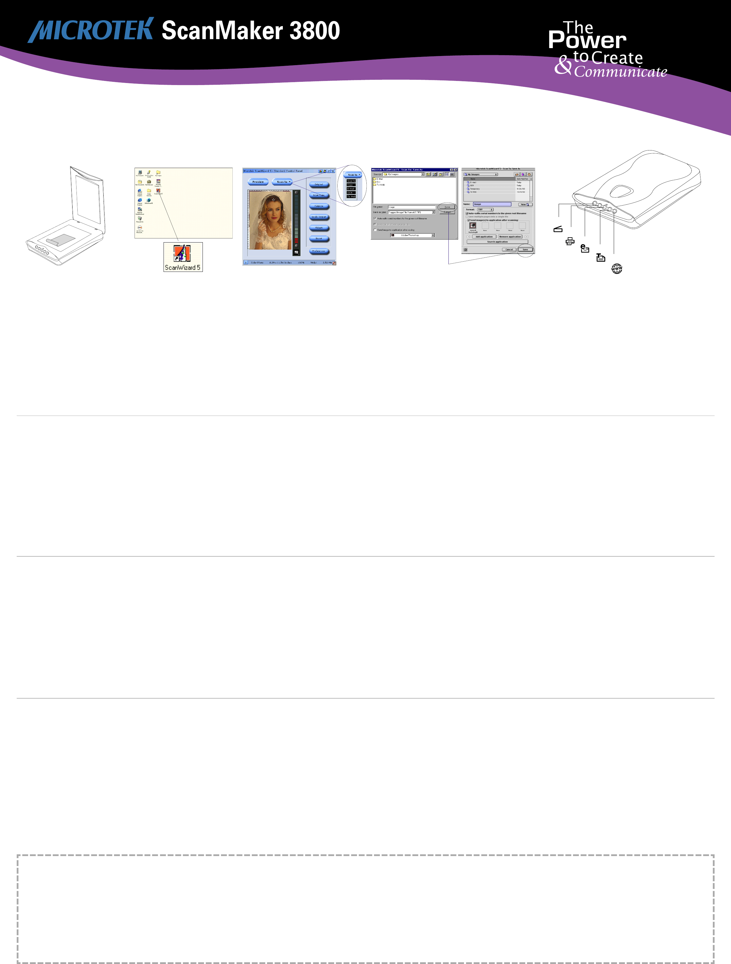
Place the scan material
A. Place the original to be scanned on the
scanner bed.
B. The top end of the original should be oriented
towards the front end of the scanner with the
surface to be scanned facing down.
Launch ScanWizard 5
To launch ScanWizard 5 as a stand-alone
program, double-click the ScanWizard 5 icon on
your desktop.
By default, the scanner will detect the settings
under Original, Scan Type and Purpose; and
automatically perform a “fast preview” of your
image based on those settings.
Select preferences
You can use the following tool buttons to change
the settings according to your preferences.
Original – defines category of the original (scan
material).
Scan Type – selects output image type (color, gray,
or B&W).
Purpose – defines image resolution to match your
target application.
NOTE: Click the Scale Output, Adjust, and Reset
buttons if you need to make further adjustments.
678
A
For More Help...
If you experience problems with installation, refer
to the Troubleshooting file in the
Techinfo
folder on
your Microtek CD- ROM.
For more information on operating your scanner
with ScanWizard 5, launch your Internet browser
to further view the software manual (in HTML
format). Alternatively, PC users can also view the
same manual directly from the Microtek CD-ROM
Installer window by simply double-clicking the
“View Manual” button.
?
Scan your material
A. Click the Scan to button from the ScanWizard
5 Control Panel.
B. When the Save As dialog box appears, specify
the folder location, a file name, and the format
for the output image, then click Save. The
image is then scanned and saved to the
specified location.
Send image to application after saving:
If this option is checked, the scanned image is
saved first, then automatically delivered to an
image-editing software, an e-mail editor, or a web
browser as indicated in the destination box.
9
Scanner Button Controls
The ScanMaker 3800 is equipped with five
scanner buttons providing quick access to the
most frequently used functions. These buttons are
Scan, Copy, E-mail, OCR , and Scan-to-Web. The
parameters for each button can be set through the
Microtek Scanner Configuration (MSC) utility.
(Note that you need to exit ScanWizard 5 before
accessing tge MSC utility)
.
To launch the MSC utility, you can either: (For PCs)
Go through the Windows menu -- click Start,
Programs, ScanWizard 5, MSC; or (For PCs or
Macs) Double-click the MSC icon on your desktop.
When the MSC panel appears, click any of the 5
tabs to specify the Scan settings accordingly.
(For
detailed information, refer to the online help in the
Microtek Scanner Configuration Utility software).
Scan
Captures images that can be saved as files or sent
to an image editing application for further
processing.
Copy
Scans image and sends it to your printer.
E-mail
Scans the image and delivers it directly to your e-
mail editor.
OCR
Scans a text document, convert and saves it as a
text file format. File may be immediately edited if
configured in the MSC utility.
Scan-to-Web
Scans an image and sends output to a website. It
opens your default browser and displays the
captured image.
PC MAC
9B
Getting Started
9A
Scan
E-mail
Copy
OCR Scan-to -Web

Federal Communications Commission Interference Statement
This equipment has been tested and found to comply with the limits for a Class B digital device, pursuant to Part 15 of the
FCC rules. These limits are designed to provide reasonable protection against harmful interference in a residential
installation. This equipment generates, uses and can radiate radio frequency energy and, if not installed and used in
accordance with the instructions, may cause harmful interference to radio communications. However, there is no
guarantee that interference will not occur in a particular installation. If this equipment does cause harmful interference to
radio or television reception, which can be determined by turning the equipment off and on, the user is encouraged to try
to correct the interference by one or more of the following measures:
• Reorient or relocate the receiving antenna.
• Increase the separation between the equipment and receiver.
• Connect the equipment into an outlet on a circuit different from that to which the receiver is connected.
• Consult the dealer or an experienced radio/TV technician for help.
FCC Caution: To assure continued compliance, (example - use only shielded interface cables when connecting to computer
or peripheral devices). Any changes or modifications not expressly approved by the party responsible for compliance could
void the user’s authority to operate this equipment.
This device complies with Part 15 of the FCC Rules. Operation is subject to the following two conditions: (1) This device
may not cause harmful interference, and (2) this device must accept any interference received, including interference that
may cause undesired operation.
Responsible Party: Loi Han
3715 Doolittle Drive
Redondo Beach, CA 90278-1226
U.S.A.
Telephone No: 1-310-297-5000
Federal Communications Commission Interference Statement
This equipment (Model: MRS-600V48U) has been tested and found to comply with the limits for a Class B digital device,
pursuant to Part 15 of the FCC Rules. These limits are designed to provide reasonable protection against harmful
interference in a residential installation. This equipment generates, uses and can radiate radio frequency energy and, if not
installed and used in accordance with the instructions, may cause harmful interference to radio communications. However,
there is no guarantee that interference will not occur in a particular installation. If this equipment does cause harmful
interference to radio or television reception, which can be determined by turning the equipment off and on, the user is
encouraged to try to correct the interference by one or more of the following measures:
• Reorient or relocate the receiving antenna.
• Increase the separation between the equipment and receiver.
• Connect the equipment into an outlet on a circuit different from that to which the receiver is connected.
• Consult the dealer or an experienced radio/TV technician for help.
Note: 1) A shielded of USB interface cable with ferrite core installed on the scanner connector end must be used with this
equipment. 2) AC adapter with ferrite core installed on the scanner connector end must be used with this equipment.
Caution: :
: :
: Changes or modifications not expressly approved by the manufacturer responsible for compliance could void the
user's authority to operate the equipment.
Trade Name Model Number
ScanMaker 3800 MRS-600V48U
Tested to Comply
With FCC Standards
FOR HOME OR OFFICE USE
Copyright © 2001 Microtek International, Inc. http://www.microtek.com April 2001
MRS-600V48U( ScanMaker 3800 ) Specifications
Scanning Modes Color, grayscale and black & white in a single scanning pass
42-bit color input and output
(approx. 281 trillion colors)
16-bit grayscale
(approx. 65,536 shades of gray)
Scanning area 8.5" x 11.7" (216 mm x 297 mm)
Resolution Optical: 600 dpi x 1200 dpi
Interpolated: 9600 dpi x 9600 dpi
Dimensions (L x W X H) 17.1" x 11.5" x 3.4"
(435 mm x 292 mm x 86 mm)
Weight 6 lbs / 2.7 kg
Voltage AC 100V to 120V (U.S. and Canada)
AC 200V to 240V (Europe and other parts)
50-60 Hz
Environment Operating temperature: 10° to 40°C (50° to 104°F)
Relative humidity: 20% to 85%