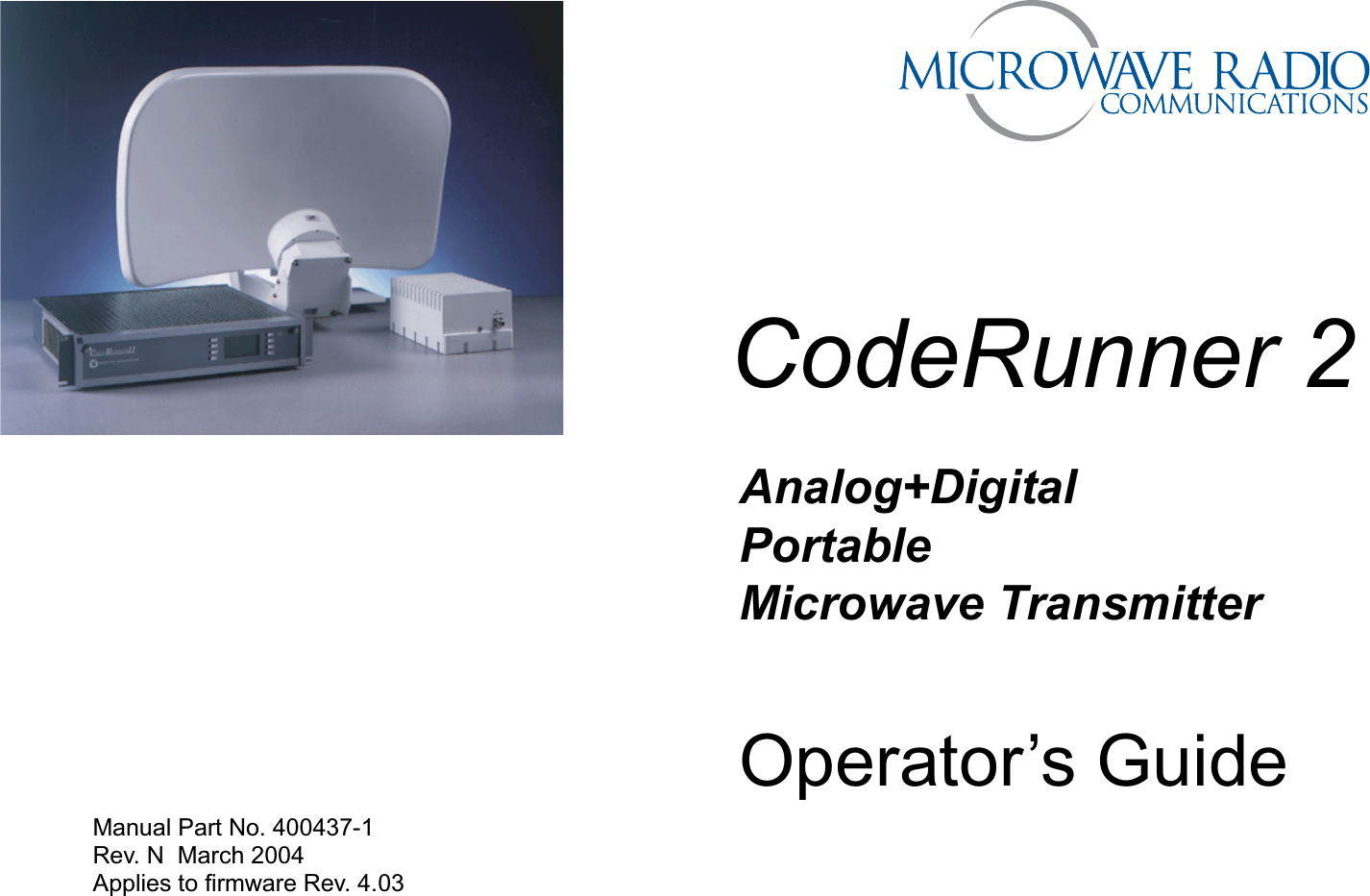
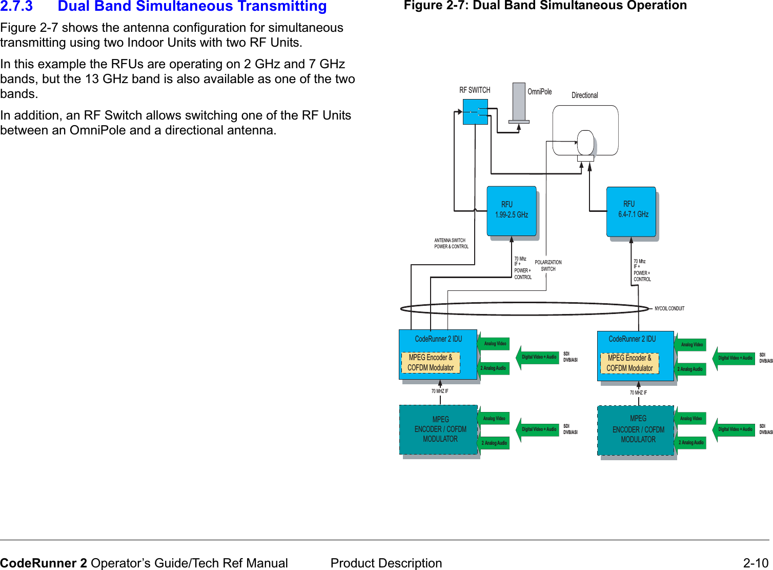
Microwave Radio Communications CR2TX2AD Microwave Transmitter User Manual CR2 Op Guide

Microwave Radio Communications LLC Microwave Transmitter CR2 Op Guide

Manual

CodeRunner 2Analog+DigitalPortableMicrowaveTransmitterOperator’s GuideManual Part No. 400437-1  Rev. N  March 2004Applies to firmware Rev. 4.03
 Notices iCodeRunner 2 Operator’s GuideNoticesAbout This ManualPart number 400437-1Revision NMarch 2004The information in the manual applies to the MRC CodeRunner 2 Transmitter, firmware revision 4.03. CopyrightThe information in this book may be reproduced by the purchaser to the extent needed for their organization. No part of this material may be modified in any way or published for resale without the express written authorization of Microwave Radio Communications. © 2004 Microwave Radio Communications Microwave Radio Communications101 Billerica Avenue - Bldg. 6North Billerica, MA 01862-1256USATEL: 978.671.5700FAX: 978.671.5800Printed in U.S.A.Proprietary MaterialThe information and design contained within this manual was originated by and is the property of Microwave Radio Communications. Microwave Radio Communications reserves all patent proprietary design, manufacturing, reproduction use, and sales rights thereto, and to any articles disclosed therein, except to the extent rights are expressly granted to others. The foregoing does not apply to vendor proprietary parts.To allow for the introduction of design improvements, specifications are subject to change without notice.Regulatory StatusThis product is certified to conform to CENELEC standards EN 55020, EN 55013, EN 50082-1 and EN 60950 and carries the CE mark.Authorized EU representative: Vislink PLC.Microwave Radio Communications is ISO 9001 certified.
 Notices-iiCodeRunner 2 Operator’s GuideRF Exposure WarningThe CodeRunner 2 is a radio transmitter.  It is designed to permit, produce and emit RF radiation into an antenna for the purpose of delivering a digital or FM modulated signal to an appropriate receiving device.  For equipment such as the CodeRunner 2, the Maximum Permissible Exposure (MPE) limit is 1.0 mW/cm2.  The CodeRunner 2 is a low-powered device, and by itself will generally not create RF exposure in excess of the MPE limits for RF radiation (OET Bulletin 65, Addition 97-01) issued by the U.S. Federal Communications Commission (FCC).  However, when properly connected to an antenna, the radiated power can exceed the MPE limits.  The purchaser and/or user of the CodeRunner 2 is solely and exclusively responsible for determining the level of RF exposure when connecting the CodeRunner 2 to an antenna or other equipment, taking all appropriate steps to limit RF exposure and for ensuring compliance with all FCC requirements set forth in OET Bulletin 65.Conventions Pay special attention to information marked in one of the following ways:CAUTION Follow CAUTIONS closely to prevent personal injury or death.WARNING Follow WARNINGS to prevent damage to the equipment.Note Notes provide additional information to assist you in using and maintaining the equipment.On-Line ViewingText displayed as blue contains a hypertext link. Click on the hypertext to jump to that destination. Click on the blue destination to return. Viewing this manual on-line requires Adobe Acrobat, version 4.0 or above. Click on this icon to download your FREE copy of Adobe Acrobat Reader.
 Notices-iiiCodeRunner 2 Operator’s GuideSymbols UsedThe following symbols are used on the equipment: Symbol MeaningCAUTION: Risk of Electric ShockWARNING: General Warning. Risk of DangerWARNING: Electrostatic Discharge. Possible Damage to EquipmentFuse - Identifies fuses or their location.Frame or Chassis Ground - Identifies the frame or chassis terminal.Earth Ground - Identifies the earth Ground TerminalProtective Earth Ground - Identifies any terminal which is intended for connection to an external conductor for protection against electric shock in case of a fault, or the terminal on a protective earth electrode.Warranty InformationProduct Manufactured by MRC:a. Products manufactured by MRC are warranted against defects in material and workmanship for a period of two (2) years from date of delivery as evidenced by MRC's packing slip or other transportation receipt (unless otherwise noted). b.MRC's sole responsibility under this warranty will be to either repair or replace, at its option, any component which fails during the applicable warranty period because of a defect in material or workmanship, provided Buyer has promptly reported same to MRC in writing. All replaced products and parts will become MRC's property.c.MRC will honor the warranty at the repair facility designated by MRC. It is Buyer's responsibility to return, at its expense, the allegedly defective product to MRC. Buyer must obtain a Return Material Authorization (RMA) number and shipping instructions from MRC prior to returning any product under warranty. Transportation charges for the return of the product to Buyer will be paid by MRC within the United States. For all other locations, the warranty excludes all costs of shipping, customs clearance and other related charges. If MRC determines that the product is not defective within the terms of this warranty, Buyer will pay MRC all costs of handling, transportation and repairs at the then prevailing repair rates.d.All the above warranties are contingent upon proper use of the product. These warranties will not apply (i) if adjustment, repair, or product or parts replacement is required because of accident, unusual physical, electrical or electromagnetic stress, neglect, misuse, failure of electric power, environmental controls, transportation, failure to maintained properly or otherwise in accordance with MRC specifications, or abuses other than
 Notices-ivCodeRunner 2 Operator’s Guideordinary use; (ii) if the product has been modified by Buyer or has been repaired or altered outside MRC's repair facility, unless MRC specifically authorizes such repairs or alterations in each instance; or (iii) where MRC serial numbers, warranty data or quality assurance decals have been removed or altered.e.No person, including any dealer, agent or representative of MRC is authorized to assume for MRC any other liability on its behalf except as set forth herein. If any payment is due MRC for services performed hereunder, it will be subject to the same payment terms as the original purchase.Products Manufactured By Others:For products not manufactured by MRC, the original manufacturer's or licensor's warranty will be assigned to Buyer to the extent permitted by the manufacturer or licensor and is in lieu of any other warranty, expressed or implied. For warranty information on a specific product, a written request should be made to MRC.All Products:THE FOREGOING WARRANTIES AND REMEDIES ARE EXCLUSIVE AND ARE IN LIEU OF ALL OTHER EXPRESS OR IMPLIED WARRANTIES, OBLIGATIONS, AND LIABILITIES ON THE PART OF MRC. EXCEPT FOR THE EXPRESS WARRANTIES STATED HEREIN, MRC DISCLAIMS ALL WARRANTIES ON PRODUCTS FURNISHED HEREUNDER, INCLUDING, WITHOUT LIMITATION, ALL IMPLIED WARRANTIES OF MERCHANTABILITY AND FITNESS FOR A PARTICULAR PURPOSE. MRC WILL HAVE NO RESPONSIBILITY FOR ANY PARTICULAR APPLICATION MADE OF ANY EQUIPMENT. Any description of equipment, whether in writing or made orally by MRC or its agents, specification sheets, models, bulletins, drawings, or similar materials used in connection with Buyer's order are for the sole purpose of identifying the equipment and will not be construed as an express warranty. Any suggestions by MRC or its agents regarding use, application or suitability of the equipment will not be construed as an express warranty. No warranties may be implied from any course of dealing or usage of trade. Buyer agrees that the exclusion of all warranties, other than those expressly provided herein, is reasonable.
 Contents iCodeRunner 2 Operator’s GuideContentsNotices  - - - - - - - - - - - - - - - - - - - - - - - - - - - - - -   iAbout This Manual - - - - - - - - - - - - - - - - - - - - - - - -   iCopyright- - - - - - - - - - - - - - - - - - - - - - - - - - - - - - -   iProprietary Material  - - - - - - - - - - - - - - - - - - - - - - -   iRegulatory Status- - - - - - - - - - - - - - - - - - - - - - - - -   iRF Exposure Warning - - - - - - - - - - - - - - - - - - - - - - - -  iiConventions - - - - - - - - - - - - - - - - - - - - - - - - - - - - - - -  iiOn-Line Viewing- - - - - - - - - - - - - - - - - - - - - - - - - -  iiSymbols Used- - - - - - - - - - - - - - - - - - - - - - - - - - - - - - iiiWarranty Information - - - - - - - - - - - - - - - - - - - - - - - - - iiiProduct Manufactured by MRC: - - - - - - - - - - - - - - - iiiProducts Manufactured By Others:- - - - - - - - - - - -   ivAll Products:  - - - - - - - - - - - - - - - - - - - - - - - - - - -   ivContents  - - - - - - - - - - - - - - - - - - - - - - - - - - - - -   iIntroduction - - - - - - - - - - - - - - - - - - - - - - - - -   1-1Chapter Overview - - - - - - - - - - - - - - - - - - - - - - - - -   1-1What This Manual Covers  - - - - - - - - - - - - - - - - - - -   1-1How It’s Organized  - - - - - - - - - - - - - - - - - - - - - - - -   1-1Who It’s Written For - - - - - - - - - - - - - - - - - - - - - - - -   1-2Related Documents - - - - - - - - - - - - - - - - - - - - - - - -   1-2Ordering documentation- - - - - - - - - - - - - - - - - - - - -   1-2Calling for Service - - - - - - - - - - - - - - - - - - - - - - - - -   1-2Product Description- - - - - - - - - - - - - - - - - - -   2-1Chapter Overview - - - - - - - - - - - - - - - - - - - - - - - - -   2-1System Description - - - - - - - - - - - - - - - - - - - - - - - -   2-1System Components - - - - - - - - - - - - - - - - - - - - - - -   2-3Operating Controls  - - - - - - - - - - - - - - - - - - - - - - - -   2-4External Connectors  - - - - - - - - - - - - - - - - - - - - - - -   2-5IDU/ODU (RFU) Interconnection- - - - - - - - - - - - - - -   2-7System Configurations - - - - - - - - - - - - - - - - - - - - - -   2-8Single Band/Dual Antenna Configuration   - - - - - -  2-8Dual Band Non-Simultaneous Transmitting - - - - -  2-9Dual Band Simultaneous Transmitting- - - - - - - -  2-10For More Information  - - - - - - - - - - - - - - - - - - - - - -  2-11Routine Operation - - - - - - - - - - - - - - - - - - - -   3-1Chapter Overview  - - - - - - - - - - - - - - - - - - - - - - - - -  3-1Overview of Controls  - - - - - - - - - - - - - - - - - - - - - - -  3-1Function Buttons  - - - - - - - - - - - - - - - - - - - - - - - - - -  3-1Polarization Select- - - - - - - - - - - - - - - - - - - - - - -  3-2Band Select  - - - - - - - - - - - - - - - - - - - - - - - - - - -  3-2Antenna Select - - - - - - - - - - - - - - - - - - - - - - - - -  3-2Status LEDs  - - - - - - - - - - - - - - - - - - - - - - - - - - - - -  3-3Display and Keypad - - - - - - - - - - - - - - - - - - - - - - - -  3-5Display Layout  - - - - - - - - - - - - - - - - - - - - - - - - -  3-5Navigating using the display and keypad - - - - - - -  3-5Frequently Performed Tasks - - - - - - - - - - - - - - - - - -  3-7Turning the power ON and OFF - - - - - - - - - - - - -  3-7Activating and deactivating the transmitter   - - - - -  3-7Switching between HI and LOW power - - - - - - - -  3-7Selecting Channel and Offset   - - - - - - - - - - - - - -  3-8Switching between antennas  - - - - - - - - - - - - - - -  3-8Switching antenna polarization   - - - - - - - - - - - - -  3-8Switching bands  - - - - - - - - - - - - - - - - - - - - - - - -  3-8Switching between Analog and Digital modes  - - -  3-8Setting for Remote operation    - - - - - - - - - - - - - -  3-9Menu Maps - - - - - - - - - - - - - - - - - - - - - - - - - - - - -  3-10Notes - Menu Maps - - - - - - - - - - - - - - - - - - - - - -   13Channels & Frequencies - - - - - - - - - - - - - - -   A-1Appendix Overview  - - - - - - - - - - - - - - - - - - - - - - - - A-1Initial Factory Presets - - - - - - - - - - - - - - - - - - - - - - - A-1US 12 MHz Channel Plan - - - - - - - - - - - - - - - - - - - - A-6Glossary - - - - - - - - - - - - - - - - - - - - - - - - - - -   B-1Index - - - - - - - - - - - - - - - - - - - - - - - - - - - - - - - -   i
 Contents-iiCodeRunner 2 Operator’s Guide
1 Introduction 1-1CodeRunner 2 Operator’s GuideIntroduction1.1 Chapter OverviewThis chapter will introduce you to the Operator’s Guide: what it covers, how it’s organized, and who it’s written for.1.2 What This Manual CoversThis manual describes how to operate the MRC CodeRunner 2 Transmitter.  For information on Installation, Repair, and Theory of Operation, refer to the MRCCodeRunner2TechnicalReferenceManual. 1.3 How It’s OrganizedThe manuals for the CodeRunner 2 are organized as follows:Chapter Operator’s GuideTechnical Reference ManualIntroductionProduct DescriptionRoutine OperationAdvanced OperationNote The Technical Reference Manual contains everything in the Operator’s Guide, plus additional technical content. InstallationTroubleshootingRepairReplacement PartsTheory of OperationAppendix A - Channels & FrequenciesAppendix B - GlossaryAppendix C - Module ReferenceAppendix D - Color Bar GeneratorAppendix E - Installing Triax ConnectorsAppendix F - Menu ReferenceChapter Operator’s GuideTechnical Reference Manual
 Introduction 1-2CodeRunner 2 Operator’s Guide1.4 Who It’s Written ForThis manual is intended for use by personnel assigned to operate the CodeRunner 2. Users of this manual should already be familiar with basic concepts of radio, video and audio.1.5 Related Documents• MRC CodeRunner 2 Quick Reference Guide (part no. 400453)• MRC CodeRunner 2 Technical Reference Manual (part no. 400465)• MRC CodeRunner 2 Helicopter Remote Control (part no. 400461)1.6 Ordering documentationAny of the above manuals may be ordered by contacting MRC Customer Service:Business Hours: Monday - Friday8:00 AM - 7:00PM Eastern Time (US)(0800 - 1900 hrs US ET)Telephone: 800-490-5700978-671-5700Fax: 978-671-5800When contacting Customer Service, please have the following information available:• Model number and serial number of the unit. This is located in two places:- label on the rear panel- label inside the front panel.• Approximate purchase date.• Firmware revision, found in two places:- displays on screen at startup- label inside the front panel.1.7 Calling for ServiceMRC Technical Support is available 24 hours a day, 7 days a week. During regular business hours you can reach our expert staff directly. After hours, your call will be forwarded to the on-call technical support specialist.Business Hours: Monday8:00 AM - 5:00PM Eastern Time (US)(0800 - 1700 hrs US ET)Tuesday - Friday8:00 AM - 7:00PM Eastern Time (US)(0800 - 1900 hrs US ET)Telephone: 800-490-5700978-671-5700Fax: 978-671-5800Email: support@mrcbroadcast.comWhen contacting Technical Support, please have the following
 Introduction 1-3CodeRunner 2 Operator’s Guideinformation available:• Model number and serial number of the unit. This is located in two places:- on a label on the rear panel- on a label inside the front panel.• Approximate purchase date.• Firmware revision, found in two places:- displays on screen at startup- on a label inside the front panel.
 Introduction 1-4CodeRunner 2 Operator’s GuideThis page intentionally left blank.
2 Product Description 2-1CodeRunner 2 Operator’s Guide/Tech Ref ManualProductDescription2.1 Chapter OverviewThis chapter provides a overall description of the product, its components, and its capabilities. Here are the topics covered:Topic PageSystem Description 2-1System Components 2-3Operating Controls 2-4External Connectors 2-5IDU/ODU (RFU) Interconnection2-7System Configurations 2-8Single Band/Dual Antenna Configuration2-8Dual Band Non-Simultaneous Transmitting2-9Dual Band Simultaneous Transmitting2-10For More Information 2-112.2 System Description  The MRC CodeRunner 2 transmitter is designed to be both an analog and digital transmitter for ENG portable applications. CodeRunner 2 can accommodate a variety of analog and digital inputs, and apply either analog or digital modulation. CodeRunner 2 is an integrated, flexible solution consisting of:• A rack mounted Indoor Unit (IDU), typically mounted inside an ENG vehicle.• A mast mounted Outdoor Unit (ODU), also called the RF Unit (RFU). A typical installation is shown in Figure 2-1.PowerOptionsThe CodeRunner 2 can be operated from 115 V / 220 V AC mains power, or from 18-36 V DC vehicle power. Power is supplied to the IDU, which in turn powers the ODU via the cable harness between them. Analog/DigitalOptionsThe CodeRunner 2 is digital-ready, which means it can be ordered and installed as a full-featured analog radio. Then later, it can be upgraded just by adding the digital MPEG/COFDM Module.Band&FrequencyOptionsThe CodeRunner 2 is designed to cover the bands below. It can be ordered as a single-band unit or in a dual-band configuration to cover any two of these bands. • 2-3 GHz• 6-7 GHz• 12-13 GHzBand and frequency information is stored in the ODU, which means switching bands after installation is very simple: just plug in the RFU for the new band, and the IDU will automatically configure itself for the new band.
 Product Description 2-2CodeRunner 2 Operator’s Guide/Tech Ref ManualWithin these bands, channels can be preprogrammed at the factory to match either the US broadcast channel plan, or a plan specified by the customer. Channel frequencies can be reprogrammed in the field using the keypad and display on the IDU.ColorBarGeneratorOptionsFor analog operation, an optional analog color bar generator is available, either at time of purchase or for later upgrade in the field. The digital MPEG/COFDM Module has a built-in digital color bar generator. Either the analog or digital generators are field configurable for functions such as auto-standby (mute the transmitter on loss of video) and auto-generate (provide tones and bars on loss of video).ConnectionOptionsThe CodeRunner 2 is designed to make upgrading from an older radio as painless as possible. The IDU and ODU can be ordered with a variety of connectors to plug into an existing wiring harness. The connectors available for the cable harness between the IDU and ODU are: •Triax• Type ‘N’•TNCThe ODU comes with a standard Type N connector for the antenna connection.AntennaOptionsThe CodeRunner 2 is fully compatible with a variety of antennas, including:• MRC ProStar, models- 2A20 and 2A20SS  (2 GHz)- 7A30 and 7A30SS  (7 GHz)- 2A20/7A30  (dual band 2 & 7 GHz)- 2A20/7A30SS (dual band 2 & 7 GHz, solid state switching)• MRC Ellipse 2000 • MRC OmniPole OmnidirectionalSwitching functions for band and antenna polarization are controlled from the front panel of the IDU. If your installation involves more than one antenna, this can be easily accommodated by using the MRC RF Switch. The RF Switch is also controlled from the front panel of the IDU.Figure 2-1: Typical CodeRunner 2 SystemAntennaOutdoor Unit (ODU)Conduit (Nycoil)Indoor Unit (IDU) (inside vehicle)Pan & Tilt Assembly
 Product Description 2-3CodeRunner 2 Operator’s Guide/Tech Ref Manual2.3 System ComponentsAn MRC CodeRunner 2 system is made up of the following components:• A rack mounted Indoor Unit (IDU), typically mounted inside an ENG vehicle. • A mast mounted Outdoor Unit (ODU), also called the RF Unit (RFU). A typical system is shown in Figure 2-2.The IDU contains the baseband circuitry, power supply, and control modules. It accepts a variety of audio and video inputs, both digital and analog, and generates a 70 MHz IF output. It also accepts IF input from external modulators.For digital operation, the IDU can be equipped with an optional internal MPEG/COFDM Module. Or, the IDU can be used with existing external digital encoders and modulators. The ODU contains the upconvertors and power amplifier. The ODU accepts the 70 MHz IF, converts it to the operating band chosen, and amplifies it.Every installation will include an antenna, either directional or omnidirectional, or both. An MRC RF Switch can be mounted up on the mast to select the antenna desired. When using a mast mounted antenna, a Nycoil conduit sheath covers the wiring harness between the IDU to the ODU. This harness carries the power, IF, and antenna band and polarization switching. Addition wiring is added for controlling the pan & tilt mechanism, and for implementing additional functions such as off-air monitors, mast lights, etc.Figure 2-2: CodeRunner 2 System ComponentsRF SwitchDirectional Antenna(MRC 2A20, 7A30, Ellipse 2000)Pan & Tilt AssemblyOutdoor RF Unit(Upconvertor,  Power Amp)Conduit (Nycoil)OmniPole AntennaCodeRunner 2 Indoor Unit(Baseband, Audio/Video Modules)ExternalModulator(Optional)ExternalEncoder(Optional)Internal MPEG Encoder &  COFDM Modulator(Optional)
 Product Description 2-4CodeRunner 2 Operator’s Guide/Tech Ref Manual2.4 Operating ControlsAll controls are on the front panel of the IDU. There are no controls or adjustments on the ODU (RFU).All transmitter functions are controlled using an LCD display with 8 button keypad, and a set of 3 function switches. See Figure 2-3 on page 2-4.The LCD display and keypad are used to toggle through control and diagnostic menus for both the IDU and ODU. Functions switches directly control antenna polarization, band selection, and antenna selection. Figure 2-3: Front Panel ControlsPOWERIDU ALARMPA ONRFU ALARMBANDSELECTPOLARIZATIONANT 1ANT 2RFU 1RFU 2LCRCHVTRANSMITTERMRC CODERUNNER 2-C/MFunction ButtonsDisplayKeypad LED IndicatorsPolarization Select Band Select Antenna Select
 Product Description 2-5CodeRunner 2 Operator’s Guide/Tech Ref Manual2.5 External ConnectorsAll transmitter connections are made at the rear panel of the IDU. The panel layout is shown in Figure 2-4. Brief descriptions of the connections are found in Table 2-1. For more detailed information, see the MRCCodeRunner2TechnicalReferenceManual. Figure 2-4: Rear Panel ConnectorsBB INVIDEO INAUX RS232 BAND 2ANT 2+RFU 2RFU 1~POWER50-60 Hz120-240V AC2A - 120V AC1A - 240V ACFEED/RELAYPOWERHOST RS232 V MON. OUTAUDIO 1AUDIO 2IF INDATA IN PAN/TILTFEEDMOD SUM ALMPOWERVHLCPGND+24VGNDRF UNIT PWR OUT--++--++RFU1 RFU2    RFSWITCH
 Product Description 2-6CodeRunner 2 Operator’s Guide/Tech Ref Manual     Table 2-1: IDU Rear Panel ConnectionsConnector FunctionSummary Alarm Input Alarm input from external device such as a modulator.Analog Video Input Input for analog video.Baseband Input Input from external baseband source. Audio Input Line level analog audio input. Data In/Out Can be used as either input or output for digital video (DVB-ASI). Configured via menus on front panel display.IF Input IF input from external modulatorRF Outputs 1 and 2 • IF + DC Power + Control to RFU (Triax Connector option)• IF + Control to RFU (Type ‘N’ and TNC connector option)Pan & Tilt Control Not UsedPower Input Supply power to CodeRunner 2 system (both IDU and RFU). Grounding Lug Connection to chassis groundRFU Power Output DC Power to RFU 1 and RFU 2 (only present with Type ‘N’ and TNC connection options).Antenna Control• FEED POWER• FEED/RELAY POWER• Control for antenna polarization, antenna band, and RF Switch.• Power for antenna and RF Switch.Video Monitor Output Analog video output to monitor the analog Color Bar Generator. Does not contain program video.Host Serial Port RS-232 data Auxiliary Serial Port RS-232 data Table 2-1: IDU Rear Panel Connections (Continued)Connector Function
 Product Description 2-7CodeRunner 2 Operator’s Guide/Tech Ref Manual2.6 IDU/ODU (RFU) InterconnectionThe IDU connects to the Outdoor RF Unit through a wiring harness inside a coiled conduit (Nycoil) sheathing. The wiring harness will contain power, RF and control for all components mounted at the top of the mast. The harness is specific to a particular installation, and is designed to support all the desired functions. These functions would typically include:• IF, control, and alarms between the IDU and ODU.• DC Power to the ODU.• Power and control for an RF Switch to select antennas. • Power and control for antenna switching functions (band, polarization).• Power for mast top lights.• Control and power for the Pan and Tilt assembly.• RF and control for an off-air antenna.• Mast top safety sensors for proximity, high voltage, etc.Since each installation is different, the harness must be specified for each installation. The harness can be supplied by MRC, or is often supplied by the van integrator.For more detailed information, see the MRCCodeRunner2TechnicalReferenceManual.
 Product Description 2-8CodeRunner 2 Operator’s Guide/Tech Ref Manual2.7 System ConfigurationsThe CodeRunner allows several antenna configurations for transmitting with either an OmniPole or directional antenna, in either single-band or dual-band operation. 2.7.1 Single Band/Dual Antenna Configuration Figure 2-6 shows the antenna configuration for single-band transmitting using one Indoor Unit with one RF Unit. The RFU could be operating on the 2 GHz, 7 GHz, or 13 GHz bands.In addition, an RF Switch allows switching between an OmniPole and a directional antenna.Figure 2-5:  Single Band Operation with 2 AntennasMRC RF SWITCHOmnPoleCodeRunner 2RFUCodeRunner 2IDU70 MhzIF + CONTROL+ POWERCOFDMMODULATORASIANTENNASWITCHPOWER &CONTROLNYCOIL CONDUITMPEG Encoder &COFDM ModulatorMPEG ENCODER/Directional2 Analog Audio2 Analog AudioAnalog VideoAnalog VideoDigital Video + Audio SDIDVB/ASIDigital Video + Audio SDIDVB/ASI
 Product Description 2-9CodeRunner 2 Operator’s Guide/Tech Ref Manual2.7.2 Dual Band Non-Simultaneous TransmittingFigure 2-6 shows the antenna configuration for non-simultaneous transmitting using one Indoor Unit with two RF Units. In this example the RFUs are operating on 2 GHz and 7 GHz bands, but the 13 GHz band is also available as one of the two bands. In addition, an RF Switch allows switching one of the RF Units between an OmniPole and a directional antenna.Figure 2-6: Dual Band, Non-Simultaneous OperationRF SWITCH OmniPoleRFU1.99-2.5 GHzCodeRunner 270 MhzIF +CONTROL +       POWER70 MhzIF +CONTROL +       POWER70 MHZ IFRFU6.4-7.1 GHzMPEGENCODER / COFDMMODULATORANTENNASWITCHPOWER/CONTROLPOLARIZATIONSWITCHMPEG Encoder &COFDM ModulatorDirectionalNYCOIL CONDUIT2 Analog Audio2 Analog AudioAnalog VideoAnalog VideoDigital Video + Audio SDIDVB/ASIDigital Video + Audio SDIDVB/ASI
 Product Description 2-10CodeRunner 2 Operator’s Guide/Tech Ref Manual2.7.3 Dual Band Simultaneous TransmittingFigure 2-7 shows the antenna configuration for simultaneous transmitting using two Indoor Units with two RF Units. In this example the RFUs are operating on 2 GHz and 7 GHz bands, but the 13 GHz band is also available as one of the two bands. In addition, an RF Switch allows switching one of the RF Units between an OmniPole and a directional antenna.Figure 2-7: Dual Band Simultaneous OperationOmniPoleRFU1.99-2.5 GHz70 MhzIF +POWER +CONTROL70 MhzIF +POWER +CONTROLRFU6.4-7.1 GHzCodeRunner 2 IDU70 MHZ IFENCODER / COFDMMODULATORNYCOIL CONDUITPOLARIZATIONSWITCHCodeRunner 2 IDU70 MHZ IFMPEGENCODER / COFDMMODULATORMPEG Encoder &COFDM ModulatorMPEG Encoder &COFDM ModulatorDirectionalMPEGRF SWITCH2 Analog Audio2 Analog AudioAnalog VideoAnalog VideoDigital Video + Audio SDIDVB/ASIDigital Video + Audio SDIDVB/ASI2 Analog Audio2 Analog AudioAnalog VideoAnalog VideoDigital Video + Audio SDIDVB/ASIDigital Video + Audio SDIDVB/ASIANTENNA SWITCHPOWER & CONTROL
 Product Description 2-11CodeRunner 2 Operator’s Guide/Tech Ref Manual2.8 For More InformationMore detailed technical information about the CodeRunner 2 can be found in the CodeRunner2TechnicalReferenceManual. Specific topics are listed below:Topic ChapterIDU     Block Diagram Theory of Operation     Operating Controls Basic Operation     Screen Menus Advanced Operation     Rear Panel Connections Installation     Supported Repairs Repair     Repair Parts Replacement PartsODU     Block Diagram Theory of Operation     Connections Installation     Supported Repairs Repair
 Product Description 2-12CodeRunner 2 Operator’s Guide/Tech Ref ManualThis page intentionally left blank.
3 Routine Operation 3-1CodeRunner 2 Operator’s Guide/Tech Ref ManualRoutineOperation3.1 Chapter OverviewThis chapter provides basic information that will enable you to operate your CodeRunner 2. More detailed information can be found in the CodeRunner 2 Technical Reference Manual. Here are the topics covered:Topic PageOverview of Controls 3-1Function Buttons 3-1Status LEDs 3-3Display and Keypad 3-5Frequently Performed Tasks 3-7Menu Maps 3-103.2 Overview of Controls The CodeRunner 2 front panel has the following controls and indicators:• Function Buttons•Status LEDs• Display and KeypadEach of these is described in more detail in the sections that follow. See Figure 3-1 on page 3-4 for the layout of the front panel. 3.3 Function ButtonsThe CodeRunner 2 provides three function buttons that control three specific functions: • Polarization Select• Band Select• Antenna SelectEach also has an LED which illuminates to show which choice is currently selected. See Figure 3-1 on page 3-4.AutomaticLockoutTo prevent accidental activation, all function buttons and keypad keys become locked out after approximately 30 seconds of inactivity. This time period is fixed and not selectable by the user.This time period is also independent of the Backlight Delay setting, which controls how long the display backlight stays on before automatically turning off. The Backlight Delay is set under the Configuration menu.To unlock the buttons and keys, press any button or key once. Then press the desired button or key to make your selection.
 Routine Operation 3-2CodeRunner 2 Operator’s Guide/Tech Ref Manual3.3.1 Polarization SelectIf your installation includes an antenna with selectable polarization (such as the MRC 2A20/7A30 or Ellipse 2000), this function button will allow you to make that selection. Pressing the Polarization Select button toggles through the four choices in sequence. As each choice is selected, the corresponding LED illuminates. The four choices are:• H (Horizontal Polarization)• V (Vertical Polarization)• RC (Right Circular Polarization)• LC (Left Circular Polarization)3.3.2 Band SelectIf your CodeRunner 2 has dual band capability, and your installation includes more than one RF Unit (RFU), this function button allows you to select which RFU is active. Pressing the Band Select button toggles back and forth between the two choices. As each choice is selected, the corresponding LED illuminates. The two choices are:•RFU1 •RFU2The IDU will automatically detect which RFU is on which band, and configure the IDU menus to match that band.3.3.3 Antenna SelectIf your installation includes more than one antenna (such as an MRC OmniPole and an MRC Ellipse 2000) and an MRC RF Switch, this function button will allow you to select which antenna is in use. Pressing the Antenna Select button toggles back and forth between the two choices. As each choice is selected, the corresponding LED illuminates. The two choices are:• ANT1 (Antenna 1) • ANT2 (Antenna 2)
 Routine Operation 3-3CodeRunner 2 Operator’s Guide/Tech Ref Manual3.4 Status LEDsThe CodeRunner 2 has four Status LEDs to keep you informed about the status of the system (See Figure 3-1 on page 3-4). Those LEDs are described in Table 3-1. Table 3-1: Status LEDsPanel Label Description ColorPOWER Indicates IDU is powered up.GreenIDU Alarm Fault condition in Indoor Unit (IDU).YellowRFU Alarm Fault condition in RF Unit (ODU).YellowPA On Power Amplifier section of RFU is powered up (actively transmitting).Green
 Routine Operation 3-4CodeRunner 2 Operator’s Guide/Tech Ref ManualFigure 3-1: Front Panel ControlsPOWERIDU ALARMPA ONRFU ALARMBANDSELECTPOLARIZATIONANT 1ANT 2RFU 1RFU 2LCRCHVTRANSMITTERMRC CODERUNNER 2-C/MFunction LEDsDisplayKeypad Status LEDsPolarization Select Band Select Antenna SelectFunction Buttons
 Routine Operation 3-5CodeRunner 2 Operator’s Guide/Tech Ref Manual3.5 Display and KeypadThe CodeRunner 2 has an LCD display and an 8-key keypad (see Figure 3-1 on page 3-4). You will use the display and keypad to set configurations, monitor status, and troubleshoot problems. Details of the individual menus are found in the CodeRunner2TechnicalReferenceManual.3.5.1 Display LayoutThe display is organized into five areas that are used for specific purposes (see Figure 3-2 on page 3-6): HeadingAreaThis is generally used for the title of the current menu screen, such as “Configuration Menu”. It is also sometimes used for displaying data or status information when the display is crowded. MessageAreaThe Message Area is used for displaying alarm and error messages, and for general status information.StatusAreaThis area is used for displaying the current settings for the available menu choices.MenuAreasThere are two menu areas, one on the right of the display and one on the left. Each can accommodate 4 menu choices, which correspond to the four keys on each side of the display.3.5.2 Navigating using the display and keypadMakingaSelectionThe eight keypad keys correspond to the eight fields in the menu areas. To select an available menu item, just press the key corresponding to that menu item.• If you selected a menu, that menu will now appear on the display.• If you changed a setting, the Status Area will change to show the new setting.AccessingtheMainMenuThe most commonly used choices and settings are available from the Main Screen. These are the choices an operator might need while using the CodeRunner 2. Choices and settings more typically performed by the technical staff are all grouped in menus accessible only through the Main Menu. To access the Main menu from the Main Screen, press the Menu key TWICE.AutomaticLockoutTo prevent accidental activation, all function buttons and keypad keys become locked out after approximately 30 seconds of inactivity. This time period is fixed and not selectable by the user.This time period is also independent of the Backlight Delay setting, which controls how long the display backlight stays on before automatically turning off. The Backlight Delay is set under the Configuration menu.To unlock the buttons and keys, press any button or key once. Then press the desired button or key to make your selection.BacklightDelayThe display includes a backlight for easy viewing in a variety of lighting conditions. The backlight can be configured to remain on, or to automatically turn off after a time delay. This Backlight Delay is set under the Configuration menu.DefaulttoMainScreenTo help prevent accidental activation of the keypad keys, the display will automatically default to the Main Screen when the Backlight turns off. If the Backlight is configured to remain on, the display continues to shown the last screen used.
 Routine Operation 3-6CodeRunner 2 Operator’s Guide/Tech Ref ManualFigure 3-2: Display and Keypad LayoutFigure 3-3:  Main Screen Display Heading AreaMessage Area Status AreaMenu AreasKeypadDi/An ANALOG STDBY PAChnl 1 17M HI Hi/LoOffst 0 2 GHz RemMenu Pwr 0.0 dBmCodeRunner.2 Rel.4.03 RFU1  Rev B
 Routine Operation 3-7CodeRunner 2 Operator’s Guide/Tech Ref Manual3.6 Frequently Performed TasksThis chapter describes how to perform many common tasks with the CodeRunner 2. Here are the tasks described:Refer to the Main Screen display in Figure 3-3, and the menu maps in Figure 3-4 and Figure 3-5 to follow along with these instructions.Topic PageTurning the power ON and OFF3-7Activating and deactivating the transmitter3-7Switching between HI and LOW power3-7Selecting Channel and Offset3-8Switching between antennas 3-8Switching antenna polarization3-8Switching bands 3-8Switching between Analog and Digital modes3-8Setting for Remote operation3-93.6.1 Turning the power ON and OFF1. Open the front panel of the Indoor Unit by loosening the 2 large screws and letting the panel swing down.2. Press the Power switch. 3. Close the front panel by swinging it up and tightening the two screws.3.6.2 Activating and deactivating the transmitter 1. Make sure the power to the CodeRunner 2 is on.2. On the Main Screen, -To activate the transmitter: press PA until the Status Area displays XMIT.-To deactivate the transmitter: press PA until the Status Area displays STDBY.3.6.3 Switching between HI and LOW power 1. Make sure the power to the CodeRunner 2 is on.2. On the Main Screen, - To switch the transmitter to High power: press Hi/Lo until the Status Area displays High.- To switch the transmitter to Low power: press Hi/Lo until the Status Area displays LOW.
 Routine Operation 3-8CodeRunner 2 Operator’s Guide/Tech Ref Manual3.6.4 Selecting Channel and Offset 1. Make sure the power to the CodeRunner 2 is on.2. On the Main Screen, - To change the channel on which the radio will transmit: press Chnl until the Status Area displays the channel desired.- To change the frequency offset above or below the selected channel: press Offst until the Status Area displays the offset desired.3.6.5 Switching between antennas 1. Make sure the power to the CodeRunner 2 is on.2. Press the Antenna Select function button until the LED illuminates next to the desired antenna.3.6.6 Switching antenna polarization 1. Make sure the power to the CodeRunner 2 is on.2. Press the Polarization Select function button until the LED illuminates next to the desired polarization.3.6.7 Switching bands Which band(s) the CodeRunner 2 operates on is set by the RFU(s) connected to the IDU. Switching bands in accomplished by switching between RFUs:1. Make sure the power to the CodeRunner 2 is on.2. Press the Band Select function button until the LED illuminates next to the desired RFU covering the desired band.3.6.8 Switching between Analog and Digital modes1. Make sure the power to the CodeRunner 2 is on.2. On the Main Screen, - To switch the transmitter to Digital mode: press Di/An until the Status Area displays DIGITAL.- To switch the transmitter to Analog mode: press Di/An until the Status Area displays ANALOG.
 Routine Operation 3-9CodeRunner 2 Operator’s Guide/Tech Ref Manual3.6.9 Setting for Remote operation  The MRC Remote Control Panel allows control of the CodeRunner 2 from the passenger compartment regardless of where in the vehicle or aircraft the CR2 is physically located. The Remote uses vehicle or aircraft power, and communicates with the IDU via an RS-232 serial interface.To set up the CR2 to operate with the Remote Control, perform the following steps on the IDU: 1. Enable remote control operation.- Make sure the CodeRunner 2 has power and is turned on.- Make sure the Remote Control Panel has power, is turned on, and is connected to IDU. - On the Main Screen, press Menu twice to access the Main Menu.- On the Main Menu screen, select Remote Menu.- On the Remote Control Menu screen, press Rmt Cntrl until the Status Area displays ENABLED.If there is a problem with the communication between the Remote Control and the IDU, the IDU Alarm LED will illuminate, and the screen will display Serial Comm Failure.  See the “Troubleshooting” chapter of the CR2TechnicalReferenceManual for help resolving the problem.2. Turn off the Modem in the Remote Control menu.- On the Remote Control Menu screen, press Modem until the Status Area displays OFF.3. Set both Transmit and Receive baud rates to 9600.- On the Remote Control Menu screen, press TxBaud until the Status Area displays 9600.- On the Remote Control Menu screen, press RxBaud until the Status Area displays 9600.4. Set Remote Control to Remote.- On the Remote Control Menu screen, select Menu.- On the Main Menu screen, select Main Screen.- On the Main Screen, press Rem until the Status Area shows RMT.Once the radio is set to RMT, the front panel controls will be partly disabled: • Navigation from one menu screen to another will work normally.• Any keys that make menu selections or change settings will be disabled.• The Function Buttons will be disabled.All these functions will be controlled by the Remote Control Panel.To restore normal front panel operation: - On the Main Screen, press Rem until the Status Area displays LCL.
 Routine Operation 3-10CodeRunner 2 Operator’s Guide/Tech Ref Manual3.7 Menu MapsFollowing are one-page menu maps to help you navigate through the many features and capabilities of your CodeRunner 2. For more detail about any of these menus or the settings available, see the CodeRunner2TechnicalReferenceManual, in the chapter “Advanced Operation”.
 Routine Operation 3-11CodeRunner 2 Operator’s Guide/Tech Ref ManualFigure 3-4: Analog Menu MapConfigura- tion MenuMain Screen Main MenuRemote Control MenuIndoorUnit MenuRF Unit Menu ModifyChannelPlanConfig MenuMenuRemote MenuIDU MenuRF UnitMod CPMenuMain MenuMain MenuMainMenuMainScreenCP SelXMIT/STDBY(displays DISABLEDContrastPABkltDlyPAAdjustContrast ContrastON/30/60/90sec/3/5minTxBaudRxBaudRmtCntrlModem ON/OFFENABLED/DISABLED150/300/1200/4800/9600/19200 150/300/1200/4800/9600/19200PwrPAChannelOffset+/-/0/++ChannelOffsetSavePwrSupply(saves changes)HI/LOW STDBY/XMIT1/2/3...10Rst Min/Max(resets min/max)<- / -> + / -(changes digits)(selects digits)1/2/3...15 +/-/0/++(displays voltages)Di/AnChnlOffstPAHi/LoANALOG1/2/3...10+/-/0/++STDBY/XMITHI/LOWDigitalVideo ModAudio ModOFDM ConfigCol Bar GenPwr Supply (displays STATUS:OK(displays STATUS:OK (displays INACTIVE)(displays status) ModeDISABLED/AUTOSTDBY/TONES+BARS/AUTOGENRst Min/Max(resets min/max)(displays voltages(auto-adjusts PA voltage)= See Notes1= Choice madeDigitalLegend14.5 /17 MHz12333344LCL/RMTRem 556
 Routine Operation 3-12CodeRunner 2 Operator’s Guide/Tech Ref ManualFigure 3-5: Digital Menu Map Configu-ration MenuMain Screen Main Menu Remote Control MenuIndoorUnit MenuRF Unit Menu Modify  ChannelPlanConfig MenuMenuRemote MenuIDU MenuRF UnitMod CPMenuMain MenuMain MenuMainMenuMain ScreenCP Sel1/2/3/4,..15 dB/AUTODi/AnChnlOffstPAHi/LoDIGITAL1/2/3...10+/-/0/++STDBY/XMITHI/LOWDigitalVideo ModAudio ModOFDM ConfigCol Bar GenPwr Supply16QAM/64QAM/QPSK(displays status) ModeOFF/ON/AUTOGENRst Min/Max(resets min/max)(displays voltages) Digital MenuModeAttnModulation  Video Modu-   lator  MenuInputChromaSDI/ ANALOG 4:2:0/ 4:2:2  Audio Modu-   lator MenuInputConfigOFF/TONE/SDI/EMBEDDEDMONO/ STEREO OFDM Config- uration  MenuBWINTERNAL BASEBANDINTERNAL COFDM ONLYEXTERNAL IFINTERNAL MPEG/COFDMINTERNAL DVB-SModFEC1/2  2/3   3/45/6  7/8CW Tone ON/OFFGI 1/32 1/161/8 1/46/7/8 MHz 16QAM/64QAM/QPSK1/2/3/4,..15 dB/AUTOAttn= Same as   Analog Map= See Notes111= Choice madeDigitalLegend1219999223414.5 /17 MHz555IDU MenuIDU MenuIDU MenuIDU MenuLCL/RMTRem 6= Same as   Analog Map678910
 Routine Operation 3-13CodeRunner 2 Operator’s Guide/Tech Ref ManualNotes - Menu MapsAnalog1. To access the Main Menu, press the Menu key twice.2. To prevent accidental activation, all menu keys and function buttons will become locked out after 30 sec. of inactivity. To unlock, press the first desired key or button twice.3. PA Adjust only operates when PA is set to XMIT.4. BkltDly (Backlight Delay) also controls whether the display defaults to the Main Screen or not. If BkltDly is set to ON- backlight stays on continuously AND - display does not default to the Main ScreenAny other setting of BkltDly will cause the backlight to turn off and the display to default to the Main Screen after the selected period of time.5. REM menu option only appears on Main Screen if RmtCntrl is set to ENABLED.6. Col Bar Gen controls the Analog Color Bar Generator.Digital1. HI/LOW power selection only operates if - Attn (Attenuation) is set to AUTOAND- Mode is set to INTERNAL MPEG/COFDM           2. The menu options for modulation are only available when- Mode is set to INTERNAL MPEG/COFDMOtherwise the menu options will not appear. Selecting any of the modulation menus will cause the display to show Disabled or Inactive.3. To access the Main Menu, press the Menu key twice.4. To prevent accidental activation, all menu keys and function buttons will become locked out after 30 sec. of inactivity. To unlock, press the first desired key or button twice.5. PA Adjust only operates when PA is set to XMIT.6. REM menu option only appears on Main Screen if RmtCntrl is set to ENABLED.
 Routine Operation 3-14CodeRunner 2 Operator’s Guide/Tech Ref Manual7. BkltDly (Backlight Delay) also controls whether the display defaults to the Main Screen or not. If BkltDly is set to ON- backlight stays on continuously AND - display does not default to the Main ScreenAny other setting of BkltDly will cause the backlight to turn off and the display to default to the Main Screen after the selected period of time.8. Col Bar Gen controls the Digital Color Bar Generator.9. The menu choices in the Video Modulator and Audio Modulator menus only appear if Mode is set to INTERNAL MPEG/COFDM.10. The only options that are implemented and functional are: - INTERNAL MPEG/COFDM- EXTERNAL IFThe remaining options:- INTERNAL BASEBAND- INTERNAL COFDM ONLY- INTERNAL DVB-Sare not implemented and are not functional.
A Channels & Frequencies A-1CodeRunner 2 Operator’s Guide/Tech Ref ManualChannels&FrequenciesA.1 Appendix OverviewThis Appendix presents the channels and frequencies that were programmed into your CR2 at the factory. It also provides the frequencies set by the latest US frequency reallocation plan.Here are the topics covered:A.2 Initial Factory PresetsThis section lists the channels and frequencies for each RF band covered by the CodeRunner 2. These frequencies are preset at the factory, but can be modified using the Channel Plan Menu, found under the “Mod CP” option on the Main Menu screen.   See the “Advanced Operation” chapter of the CR2TechnicalReferenceManual.Note These frequency settings should only be changed by qualified technical personnel.Topic PageInitial Factory Presets A-1US 12 MHz Channel Plan A-6
 Channels & Frequencies A-2CodeRunner 2 Operator’s Guide/Tech Ref ManualTable A-1: 2 GHz RF Channel Guide (U.S. Broadcast) - 17 MHz Channel PlanChannel (-) Offset (MHz) (0) Center (MHz) (+) Offset (MHz) (++) Offset (MHz)-4.25MHz 17.0MHzspacing+4.25MHz1 1994.75 1999.0 2003.25 00000.0002 2012.25 2016.5 2020.75 00000.0003 2029.25 2033.5 2037.75 00000.0004 2046.25 2050.5 2054.75 00000.0005 2063.25 2067.5 2071.75 00000.0006 2080.25 2084.5 2088.75 00000.0007 2097.25 2101.5 2105.75 00000.0008 2454.25 2458.5 2462.75 00000.0009 2471.25 2475.5 2479.75 00000.00010 2487.75 2492.0 2496.25 00000.00011 00000.000 00000.000 00000.000 00000.00012 00000.000 00000.000 00000.000 00000.00013 00000.000 00000.000 00000.000 00000.00014 00000.000 00000.000 00000.000 00000.00015 00000.000 00000.000 00000.000 00000.000
 Channels & Frequencies A-3CodeRunner 2 Operator’s Guide/Tech Ref ManualNote As of the publication of this manual, the 14.5 MHz channel plan was not approved for use in the US.Table A-2: 2 GHz RF Channel Guide (U.S. Broadcast) - 14.5 MHz Channel PlanChannel (-) Offset (MHz) (0) Center (MHz) (+) Offset (MHz) (++) Offset (MHz)-4.25MHz 14.5MHzspacing+4.25MHz1 2012.00 2015.50 2019.00 00000.0002 2026.75 2030.25 2033.75 00000.0003 2041.25 2044.75 2048.25 00000.0004 2055.75 2059.25 2062.75 00000.0005 2070.25 2073.75 2077.25 00000.0006 2084.75 2088.25 2091.75 00000.0007 2099.25 2102.75 2106.25 00000.0008 2454.25 2458.50 2462.75 00000.0009 2471.25 2475.50 2479.75 00000.00010 2487.75 2492.00 2496.25 00000.00011 00000.000 00000.000 00000.000 00000.00012 00000.000 00000.000 00000.000 00000.00013 00000.000 00000.000 00000.000 00000.00014 00000.000 00000.000 00000.000 00000.00015 00000.000 00000.000 00000.000 00000.000
 Channels & Frequencies A-4CodeRunner 2 Operator’s Guide/Tech Ref ManualTable A-3: 6/7 GHz RF Channel Guide (U.S. Broadcast)Channel (-) Offset (MHz) (0) Center (MHz) (+) Offset (MHz) (++) Offset (MHz)-6.25MHz 25.0MHzspacing+6.25MHz1 6881.25 6887.50 6893.75 00000.0002 6906.25 6912.50 6918.75 00000.0003 6913.25 6937.50 6943.75 00000.0004 6956.25 6962.50 6968.75 00000.0005 6981.25 6987.50 6993.75 00000.0006 7006.25 7012.50 7018.75 00000.0007 7031.25 7037.50 7043.75 00000.0008 7056.25 7062.50 7068.75 00000.0009 7081.25 7087.50 7093.75 00000.00010 7106.25 7112.50 7118.75 00000.00011 00000.000 00000.000 00000.000 00000.00012 00000.000 00000.000 00000.000 00000.00013 00000.000 00000.000 00000.000 00000.00014 00000.000 00000.000 00000.000 00000.00015 00000.000 00000.000 00000.000 00000.000
 Channels & Frequencies A-5CodeRunner 2 Operator’s Guide/Tech Ref ManualTable A-4: 12/13 GHz RF Channel Guide (U.S. Broadcast)Channel (-) Offset (MHz) (0) Center (MHz) (+) Offset (MHz) (++) Offset (MHz)-6.25MHz 25.0MHzspacing+6.25MHz -----1 12706.25 12712.50 12718.75 00000.0002 12731.25 12737.50 12743.75 00000.0003 12756.25 12762.50 12768.75 00000.0004 12781.25 12787.50 12793.75 00000.0005 12806.25 12812.50 12818.75 00000.0006 12831.25 12837.50 12843.75 00000.0007 12856.25 12862.50 12868.75 00000.0008 12881.25 12887.50 12893.75 00000.0009 12906.25 12912.50 12918.75 00000.00010 12931.25 12937.50 12943.75 00000.00011 12956.25 12962.50 12968.75 00000.00012 12981.25 12987.50 12993.75 00000.00013 13006.25 13012.50 13018.75 00000.00014 13031.25 13037.50 13043.75 00000.00015 13056.25 13062.50 13068.75 00000.00016 13081.25 13087.50 13093.75 00000.00017 13106.25 13112.50 13118.75 00000.00018 13131.25 13137.50 13143.75 00000.00019 13156.25 13162.50 13168.75 00000.00020 13181.25 13187.50 13193.75 00000.00021 13206.25 13212.50 13218.75 00000.00022 13231.25 13237.50 13243.74 00000.000
 Channels & Frequencies A-6CodeRunner 2 Operator’s Guide/Tech Ref ManualA.3 US 12 MHz Channel PlanHere are the frequencies that will be used in the new US 12 MHz channel plan. Your CR2 is pre-programmed with the frequencies listed in Section A.2 on page A-1. However, as your station migrates to the new channel plan, you can easily reprogram your CR2 using the Channel Plan Menu, found under the “Mod CP” option on the Main Menu screen. See the “Advanced Operation” chapter of the CR2TechnicalReferenceManual.Information below was obtained from the FCC Web site, document # FCC 03-280:http://hraunfoss.fcc.gov/edocs_public/attachmatch/FCC-03-280A1.pdfTable A-5: US 12 MHz Channel PlanFrequencies (MHz) Channel Width DescriptionLower Upper2025.0 2025.5 500 kHz Lower Data Return Link (DRL) Band2025.5 2037.5 12 MHz Channel A1r2037.5 2049.5 12 MHz Channel A2r2049.5 2061.5 12 MHz Channel A3r2061.5 2073.5 12 MHz Channel A4r2073.5 2085.5 12 MHz Channel A5r2085.5 2097.5 12 MHz Channel A6r2097.5 2109.5 12 MHz Channel A7r2109.5 2110.0 500 kHz Upper Data Return Link (DRL) Band
B Glossary B-1CodeRunner 2 Operator’s Guide/Tech Ref ManualGlossaryThis section describes acronyms and abbreviations used in communications, broadcasting, and in MRC Products and documentation. Table B-1: Useful Terms Term Explanation16QAM 16-state Quadrature Amplitude ModulationThe signal (video+audio) is imposed onto the 70 MHz carrier by varying both the phase and the amplitude of the signal while keeping the frequency constant. There are 16 possible combinations of phase and amplitude that can be used to carry information.3RU 3 Rack Unit height.4FSK 4-state Frequency Shift Keying64QAM 64-state Quadrature Amplitude ModulationThe signal (video+audio) is imposed onto the 70 MHz carrier by varying both the phase and the amplitude of the signal while keeping the frequency constant. There are 64 possible combinations of phase and amplitude that can be used to carry information.A & C Alarm and Control.ADPCM Adaptive Differential Pulse Code Modulation.AFC Automatic Frequency Control.AGC Automatic Gain Control.AIS Alarm Indication Signal (all one’s).AMI Alternate Mark Inversion, line code format for traffic data.AVG Average.ASI Asynchronous Serial InterfaceA serial communications interface operating at 270 Mbit/sec., generally used in field news-gathering operations. Baseband A composite signal in which video and audio signals are combined together, with video occupying approximately 0-4.5 MHz and audio modulated onto subcarriers in the 5-6MHz range. Also called Composite.B8ZS Bipolar 8 Zero Substitution, line code format for traffic data.BB Baseband.BER Bit Error Rate.BiasT A type of interconnection between the IDU and the ODU. In Bias T wiring, IF and DC are combined and carried on the coax cable up the ODU; blocking circuitry prevents the DC from entering the IDU.BNC Bayonet lock coaxial connector.BPF Band Pass Filter.BPS Bits per second.BPSK Binary Phase Shift KeyingCCITT International Telegraph and Telephone Consultative Committee, a telecommunications standardizing committee of the ITU.CNR Carrier-to-Noise RatioCOFDM Coded Orthogonal Frequency Division MultiplexingTable B-1: Useful Terms  (Continued)
 Glossary B-2CodeRunner 2 Operator’s Guide/Tech Ref ManualComposite (Baseband)A band or grouping of frequencies and/or subcarriers, including video, occupied by the signal in a radio transmission system. Also called Baseband.Composite VideoVideo signal in which the chrominance (color) and luminance (brightness) information are combined in one signal. S-Video separates the chrominance and luminance into separate signals.CSI Channel-State InformationCW Carrier WaveDAB Digital Audio BroadcastingdB Decibel. A logarithmic measurement, applied to audio and RF signals. dBm A unit of measurement referenced to one milliwatt.DFT Discrete Fourier TransformDMUX, DEMUXDemultiplexerDQPSK Differential Quadrature (Quaternary) Phase-Shift KeyingDuplex A channel capable of transmitting information simultaneously in either direction.DVB Digital Video BroadcastingDVB-S Digital Video Broadcasting - SatelliteDVB-T Digital Video Broadcasting - TerrestrialE1 2.048 Mbps traffic rate.EIA Electronic Industries Association, an industry association that establishes various standards.EMC Electromagnetic compatibility.ERRS Errors.ESD Electrostatic discharge.Table B-1: Useful Terms  (Continued)ETSI European Telecommunications Standards InstituteFCC Federal Communications Commission, the United State's communications regulatory agency.FDM Frequency Division MultiplexingFFT Fast Fourier TransformFIFO First in, first out buffer.FIR Finite Impulse Response.FLR MRC's model designation for frequency modulated (FM) remodulating radio systems from 2 to 15 GHz. FLR2 is the 2 GHz band version; FLR4, the 4 GHz band version, etc.FMT FM Video ModulatorFPGA Field Programmable Gate Array.FSK Frequency-Shift KeyingGND Ground.H/W Hardware.HDB3 High Density Bipolar 3 line code format for traffic data.HPF High Pass Filter.I In phaseICI Inter-Carrier InterferenceID Identification.IDU Indoor UnitIF Intermediate Frequency.Table B-1: Useful Terms  (Continued)
 Glossary B-3CodeRunner 2 Operator’s Guide/Tech Ref ManualIRE 1. Institute of Radio Engineers, an international professional radio engineering association that establishes various standards.2. A unit of measurement, established by the IRE, in which 1 IRE Unit =.00714 volts peak-to-peak (Vp-p) and 140 IRE units equals 1 Vp-p.ISI Inter-Symbol InterferenceKbps Kilobits per second.KHz Kilo (1,000) cycles per second.LCD Liquid Crystal DisplayLcl LocalLED Light emitting diode.LO Local OscillatorLOS Loss of Signal.LPF Low Pass Filter.Mbps Megabits per second.MHz Million (1,000,000) cycles per second.MUX Multiplexer.NICAM Near-Instantaneous Companding and MultiplexingNRZ Near Return to Zero.ODU Outdoor Unit - also called RF Unit or RFUOFDM Orthogonal Frequency Division MultiplexingØLK Phase Lock.PER Parity Error Rate.PLL Phase Lock Loop.Q Quadature phase.QAM Quadrature Amplitude ModulationTable B-1: Useful Terms  (Continued)QPSK Quadrature Phase Shift KeyingThe signal (video+audio) is imposed onto the 70 MHz carrier by varying the phase of the signal while keeping the amplitude and frequency constant. There are 4 possible values of phase that can be used to carry information.RCL Received Carrier Level.Rcvr Receiver.RDS Radio Data SystemRF Radio Frequency, any frequency of electromagnetic radiation or alternating currents in the range from 3 kHz to 300 GHz; as in RF Signal or RF Transmission.RF Level RF Power from the transmitter.RFU Radio Frequency Unit - also called ODUR-S Reed-SolomonRx Receiver.S/W Software.SC Service Channel.SC Single CarrierSDI Synchronous Digital InterfaceA serial communications interface operating at 270 Mbit/sec., generally used for in-studio news operations. SER Symbol Error RateSetpt Set point.SFN Single-Frequency NetworkSimplex A channel capable of transmitting information in only one direction.Table B-1: Useful Terms  (Continued)
 Glossary B-4CodeRunner 2 Operator’s Guide/Tech Ref ManualSite ID A physical location where any number of modems, transmitters, or receivers are installed.SMPTE Society of Motion Picture and Television EngineersSNR Signal-to-Noise RatioSTDBY Standby.Subcarrier An electromagnetic signal that is used as a medium for placing an information channel above another information channel.S-Video Video signal in which the chrominance (color) and luminance (brightness) information are separated into separate subcarrier signals. Also called Y/C Video. Composite Video combines them into one signal.SYNTH SynthesizerT1 1.544 Mbps traffic rate.Tx Transmitter.VCO Voltage Controlled Oscillator.VCXO Voltage Controlled Crystal Oscillator.VDC Volts Direct Current.VF Voice Frequency.Video A term pertaining to the bandwidth and spectrum of the signal that results from television scanning and which is used to reproduce a picture.Xmitr Transmitter.Xmtr Transmitter.Y/C Video signal in which the chrominance (color) and luminance (brightness) information are separated into separate subcarrier signals. Also called S-Video. Composite Video combines them into one signal.Table B-1: Useful Terms  (Continued)
 Index iCodeRunner 2 Operator’s GuideIndexNumerics16QAMB-14FSKB-164QAMB-1AASIB-1Audience, Intended1-2BBacklight DelayDescription3-5BasebandB-1CChannels and FrequenciesA-1Initial Factory PresetsA-1US 12MHz PlanA-6COFDMB-1Composite (Baseband)B-2Composite VideoB-2ConnectorsExternal2-5Layout2-5Rear Panel2-5ControlsDescription2-4Display3-5Display and Keypad3-5Front Panel2-4Function Buttons3-1Antenna Select3-2Band Select3-2Polarization Select3-2Layout2-4Overview3-1DDisplayLayout3-5,3-6Navigating3-5DocumentsOrdering1-2Related1-2DVBB-2DVB-SB-2DVB-TB-2FFrequently Performed Tasks3-7Activate Transmitter3-7Deactivate Transmitter3-7Selecting Channel3-8Selecting Offset3-8Set High Power3-7Set Low Power3-7Switch Antennas3-8Switching Bands3-8Switching Polarization3-8Turn power off3-7Turn power on3-7Turn power on/off3-7FSKB-2Function Buttons3-1GGlossaryB-1
 Index iiCodeRunner 2 Operator’s GuideIIndoor UnitConnection to Outdoor Unit2-7KKeypad3-5Layout3-6LLEDsFunction3-1Status3-3Lockout, Automatic3-1MMain MenuAccessing3-5Main Screen3-5Maps, Menu3-10Menu Maps3-10Analog3-11Digital3-12Notes3-13OODUB-3OFDMB-3Operating Controls2-4Operating NotesRemote Control Panel3-9OptionsAnalog/Digital2-1Antenna2-2Band2-1Color Bar Generator2-2Connection2-2Frequency2-1Power2-1Outdoor UnitConnection to Indoor Unit2-7RRemote ControlOperating3-9SStatus LEDs3-3SubcarrierB-4SYNTHB-4SystemComponents2-3Configurations2-8Description2-1VVideoB-4

Navigation menu