Microwave Radio Communications CR2TX2AD Microwave Transmitter User Manual CR2 Op Guide
Microwave Radio Communications LLC Microwave Transmitter CR2 Op Guide
Manual
CodeRunner 2
Analog+Digital
Portable
MicrowaveTransmitter
Operator’s Guide
Manual Part No. 400437-1
Rev. N March 2004
Applies to firmware Rev. 4.03

Notices iCodeRunner 2 Operator’s Guide
Notices
About This Manual
Part number 400437-1
Revision N
March 2004
The information in the manual applies to the MRC CodeRunner 2
Transmitter, firmware revision 4.03.
Copyright
The information in this book may be reproduced by the
purchaser to the extent needed for their organization. No part of
this material may be modified in any way or published for resale
without the express written authorization of Microwave Radio
Communications.
© 2004 Microwave Radio Communications
Microwave Radio Communications
101 Billerica Avenue - Bldg. 6
North Billerica, MA 01862-1256USA
TEL: 978.671.5700
FAX: 978.671.5800
Printed in U.S.A.
Proprietary Material
The information and design contained within this manual was
originated by and is the property of Microwave Radio
Communications. Microwave Radio Communications reserves
all patent proprietary design, manufacturing, reproduction use,
and sales rights thereto, and to any articles disclosed therein,
except to the extent rights are expressly granted to others. The
foregoing does not apply to vendor proprietary parts.
To allow for the introduction of design improvements,
specifications are subject to change without notice.
Regulatory Status
This product is certified to conform to CENELEC standards EN
55020, EN 55013, EN 50082-1 and EN 60950 and carries the
CE mark.
Authorized EU representative: Vislink PLC.
Microwave Radio Communications is ISO 9001 certified.

Notices-iiCodeRunner 2 Operator’s Guide
RF Exposure Warning
The CodeRunner 2 is a radio transmitter. It is designed to
permit, produce and emit RF radiation into an antenna for the
purpose of delivering a digital or FM modulated signal to an
appropriate receiving device.
For equipment such as the CodeRunner 2, the Maximum
Permissible Exposure (MPE) limit is 1.0 mW/cm2. The
CodeRunner 2 is a low-powered device, and by itself will
generally not create RF exposure in excess of the MPE limits for
RF radiation (OET Bulletin 65, Addition 97-01) issued by the U.S.
Federal Communications Commission (FCC). However, when
properly connected to an antenna, the radiated power can
exceed the MPE limits.
The purchaser and/or user of the CodeRunner 2 is solely and
exclusively responsible for determining the level of RF exposure
when connecting the CodeRunner 2 to an antenna or other
equipment, taking all appropriate steps to limit RF exposure and
for ensuring compliance with all FCC requirements set forth in
OET Bulletin 65.
Conventions
Pay special attention to information marked in one of the
following ways:
CAUTION Follow CAUTIONS closely to prevent
personal injury or death.
WARNING Follow WARNINGS to prevent damage to
the equipment.
Note Notes provide additional information to assist you
in using and maintaining the equipment.
On-Line Viewing
Text displayed as blue contains a hypertext link. Click on the
hypertext to jump to that destination. Click on the
blue destination to return.
Viewing this manual on-line
requires Adobe Acrobat,
version 4.0 or above.
Click on this icon to download your
FREE copy of Adobe Acrobat
Reader.
Notices-iiiCodeRunner 2 Operator’s Guide
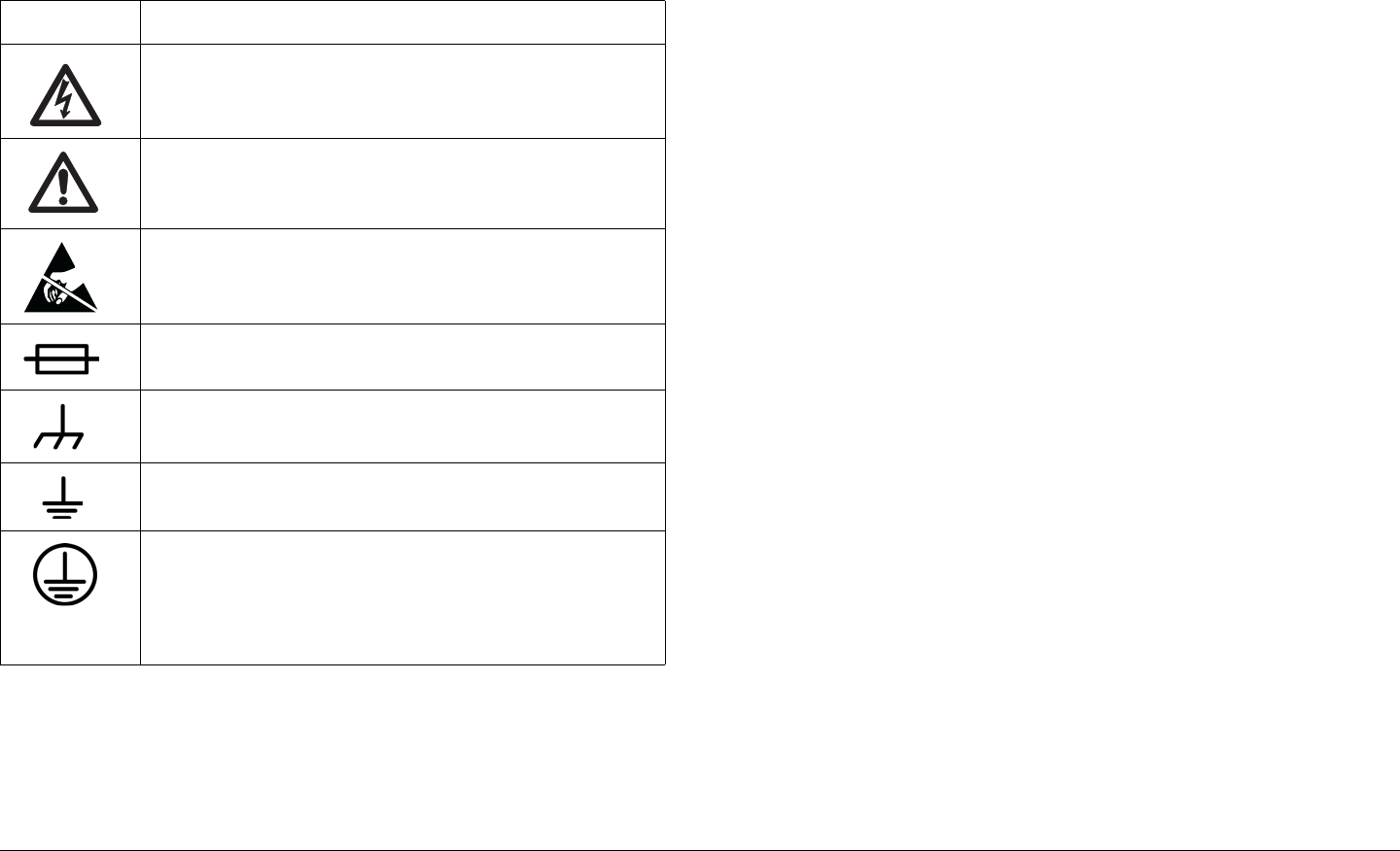
Symbols Used
The following symbols are used on the equipment:
Symbol Meaning
CAUTION: Risk of Electric Shock
WARNING: General Warning. Risk of Danger
WARNING: Electrostatic Discharge. Possible
Damage to Equipment
Fuse - Identifies fuses or their location.
Frame or Chassis Ground - Identifies the frame or
chassis terminal.
Earth Ground - Identifies the earth Ground Terminal
Protective Earth Ground - Identifies any terminal
which is intended for connection to an external
conductor for protection against electric shock in
case of a fault, or the terminal on a protective earth
electrode.
Warranty Information
Product Manufactured by MRC:
a. Products manufactured by MRC are warranted against
defects in material and workmanship for a period of two (2) years
from date of delivery as evidenced by MRC's packing slip or
other transportation receipt (unless otherwise noted).
b.MRC's sole responsibility under this warranty will be to either
repair or replace, at its option, any component which fails during
the applicable warranty period because of a defect in material or
workmanship, provided Buyer has promptly reported same to
MRC in writing. All replaced products and parts will become
MRC's property.
c.MRC will honor the warranty at the repair facility designated
by MRC. It is Buyer's responsibility to return, at its expense, the
allegedly defective product to MRC. Buyer must obtain a Return
Material Authorization (RMA) number and shipping instructions
from MRC prior to returning any product under warranty.
Transportation charges for the return of the product to Buyer will
be paid by MRC within the United States. For all other locations,
the warranty excludes all costs of shipping, customs clearance
and other related charges. If MRC determines that the product is
not defective within the terms of this warranty, Buyer will pay
MRC all costs of handling, transportation and repairs at the then
prevailing repair rates.
d.All the above warranties are contingent upon proper use of
the product. These warranties will not apply (i) if adjustment,
repair, or product or parts replacement is required because of
accident, unusual physical, electrical or electromagnetic stress,
neglect, misuse, failure of electric power, environmental controls,
transportation, failure to maintained properly or otherwise in
accordance with MRC specifications, or abuses other than

Notices-ivCodeRunner 2 Operator’s Guide
ordinary use; (ii) if the product has been modified by Buyer or
has been repaired or altered outside MRC's repair facility, unless
MRC specifically authorizes such repairs or alterations in each
instance; or (iii) where MRC serial numbers, warranty data or
quality assurance decals have been removed or altered.
e.No person, including any dealer, agent or representative of
MRC is authorized to assume for MRC any other liability on its
behalf except as set forth herein. If any payment is due MRC for
services performed hereunder, it will be subject to the same
payment terms as the original purchase.
Products Manufactured By Others:
For products not manufactured by MRC, the original
manufacturer's or licensor's warranty will be assigned to Buyer to
the extent permitted by the manufacturer or licensor and is in lieu
of any other warranty, expressed or implied. For warranty
information on a specific product, a written request should be
made to MRC.
All Products:
THE FOREGOING WARRANTIES AND REMEDIES ARE
EXCLUSIVE AND ARE IN LIEU OF ALL OTHER EXPRESS OR
IMPLIED WARRANTIES, OBLIGATIONS, AND LIABILITIES ON
THE PART OF MRC. EXCEPT FOR THE EXPRESS
WARRANTIES STATED HEREIN, MRC DISCLAIMS ALL
WARRANTIES ON PRODUCTS FURNISHED HEREUNDER,
INCLUDING, WITHOUT LIMITATION, ALL IMPLIED
WARRANTIES OF MERCHANTABILITY AND FITNESS FOR A
PARTICULAR PURPOSE. MRC WILL HAVE NO
RESPONSIBILITY FOR ANY PARTICULAR APPLICATION
MADE OF ANY EQUIPMENT. Any description of equipment,
whether in writing or made orally by MRC or its agents,
specification sheets, models, bulletins, drawings, or similar
materials used in connection with Buyer's order are for the sole
purpose of identifying the equipment and will not be construed as
an express warranty. Any suggestions by MRC or its agents
regarding use, application or suitability of the equipment will not
be construed as an express warranty. No warranties may be
implied from any course of dealing or usage of trade. Buyer
agrees that the exclusion of all warranties, other than those
expressly provided herein, is reasonable.

Contents iCodeRunner 2 Operator’s Guide
Contents
Notices - - - - - - - - - - - - - - - - - - - - - - - - - - - - - - i
About This Manual - - - - - - - - - - - - - - - - - - - - - - - - i
Copyright- - - - - - - - - - - - - - - - - - - - - - - - - - - - - - - i
Proprietary Material - - - - - - - - - - - - - - - - - - - - - - - i
Regulatory Status- - - - - - - - - - - - - - - - - - - - - - - - - i
RF Exposure Warning - - - - - - - - - - - - - - - - - - - - - - - - ii
Conventions - - - - - - - - - - - - - - - - - - - - - - - - - - - - - - - ii
On-Line Viewing- - - - - - - - - - - - - - - - - - - - - - - - - - ii
Symbols Used- - - - - - - - - - - - - - - - - - - - - - - - - - - - - - iii
Warranty Information - - - - - - - - - - - - - - - - - - - - - - - - - iii
Product Manufactured by MRC: - - - - - - - - - - - - - - - iii
Products Manufactured By Others:- - - - - - - - - - - - iv
All Products: - - - - - - - - - - - - - - - - - - - - - - - - - - - iv
Contents - - - - - - - - - - - - - - - - - - - - - - - - - - - - - i
Introduction - - - - - - - - - - - - - - - - - - - - - - - - - 1-1
Chapter Overview - - - - - - - - - - - - - - - - - - - - - - - - - 1-1
What This Manual Covers - - - - - - - - - - - - - - - - - - - 1-1
How It’s Organized - - - - - - - - - - - - - - - - - - - - - - - - 1-1
Who It’s Written For - - - - - - - - - - - - - - - - - - - - - - - - 1-2
Related Documents - - - - - - - - - - - - - - - - - - - - - - - - 1-2
Ordering documentation- - - - - - - - - - - - - - - - - - - - - 1-2
Calling for Service - - - - - - - - - - - - - - - - - - - - - - - - - 1-2
Product Description- - - - - - - - - - - - - - - - - - - 2-1
Chapter Overview - - - - - - - - - - - - - - - - - - - - - - - - - 2-1
System Description - - - - - - - - - - - - - - - - - - - - - - - - 2-1
System Components - - - - - - - - - - - - - - - - - - - - - - - 2-3
Operating Controls - - - - - - - - - - - - - - - - - - - - - - - - 2-4
External Connectors - - - - - - - - - - - - - - - - - - - - - - - 2-5
IDU/ODU (RFU) Interconnection- - - - - - - - - - - - - - - 2-7
System Configurations - - - - - - - - - - - - - - - - - - - - - - 2-8
Single Band/Dual Antenna Configuration - - - - - - 2-8
Dual Band Non-Simultaneous Transmitting - - - - - 2-9
Dual Band Simultaneous Transmitting- - - - - - - - 2-10
For More Information - - - - - - - - - - - - - - - - - - - - - - 2-11
Routine Operation - - - - - - - - - - - - - - - - - - - - 3-1
Chapter Overview - - - - - - - - - - - - - - - - - - - - - - - - - 3-1
Overview of Controls - - - - - - - - - - - - - - - - - - - - - - - 3-1
Function Buttons - - - - - - - - - - - - - - - - - - - - - - - - - - 3-1
Polarization Select- - - - - - - - - - - - - - - - - - - - - - - 3-2
Band Select - - - - - - - - - - - - - - - - - - - - - - - - - - - 3-2
Antenna Select - - - - - - - - - - - - - - - - - - - - - - - - - 3-2
Status LEDs - - - - - - - - - - - - - - - - - - - - - - - - - - - - - 3-3
Display and Keypad - - - - - - - - - - - - - - - - - - - - - - - - 3-5
Display Layout - - - - - - - - - - - - - - - - - - - - - - - - - 3-5
Navigating using the display and keypad - - - - - - - 3-5
Frequently Performed Tasks - - - - - - - - - - - - - - - - - - 3-7
Turning the power ON and OFF - - - - - - - - - - - - - 3-7
Activating and deactivating the transmitter - - - - - 3-7
Switching between HI and LOW power - - - - - - - - 3-7
Selecting Channel and Offset - - - - - - - - - - - - - - 3-8
Switching between antennas - - - - - - - - - - - - - - - 3-8
Switching antenna polarization - - - - - - - - - - - - - 3-8
Switching bands - - - - - - - - - - - - - - - - - - - - - - - - 3-8
Switching between Analog and Digital modes - - - 3-8
Setting for Remote operation - - - - - - - - - - - - - - 3-9
Menu Maps - - - - - - - - - - - - - - - - - - - - - - - - - - - - - 3-10
Notes - Menu Maps - - - - - - - - - - - - - - - - - - - - - - 13
Channels & Frequencies - - - - - - - - - - - - - - - A-1
Appendix Overview - - - - - - - - - - - - - - - - - - - - - - - - A-1
Initial Factory Presets - - - - - - - - - - - - - - - - - - - - - - - A-1
US 12 MHz Channel Plan - - - - - - - - - - - - - - - - - - - - A-6
Glossary - - - - - - - - - - - - - - - - - - - - - - - - - - - B-1
Index - - - - - - - - - - - - - - - - - - - - - - - - - - - - - - - - i

Contents-iiCodeRunner 2 Operator’s Guide
1
Introduction 1-1CodeRunner 2 Operator’s Guide
Introduction
1.1 Chapter Overview
This chapter will introduce you to the Operator’s Guide: what it
covers, how it’s organized, and who it’s written for.
1.2 What This Manual Covers
This manual describes how to operate the MRC CodeRunner 2
Transmitter.
For information on Installation, Repair, and Theory of Operation,
refer to the MRCCodeRunner2TechnicalReferenceManual.
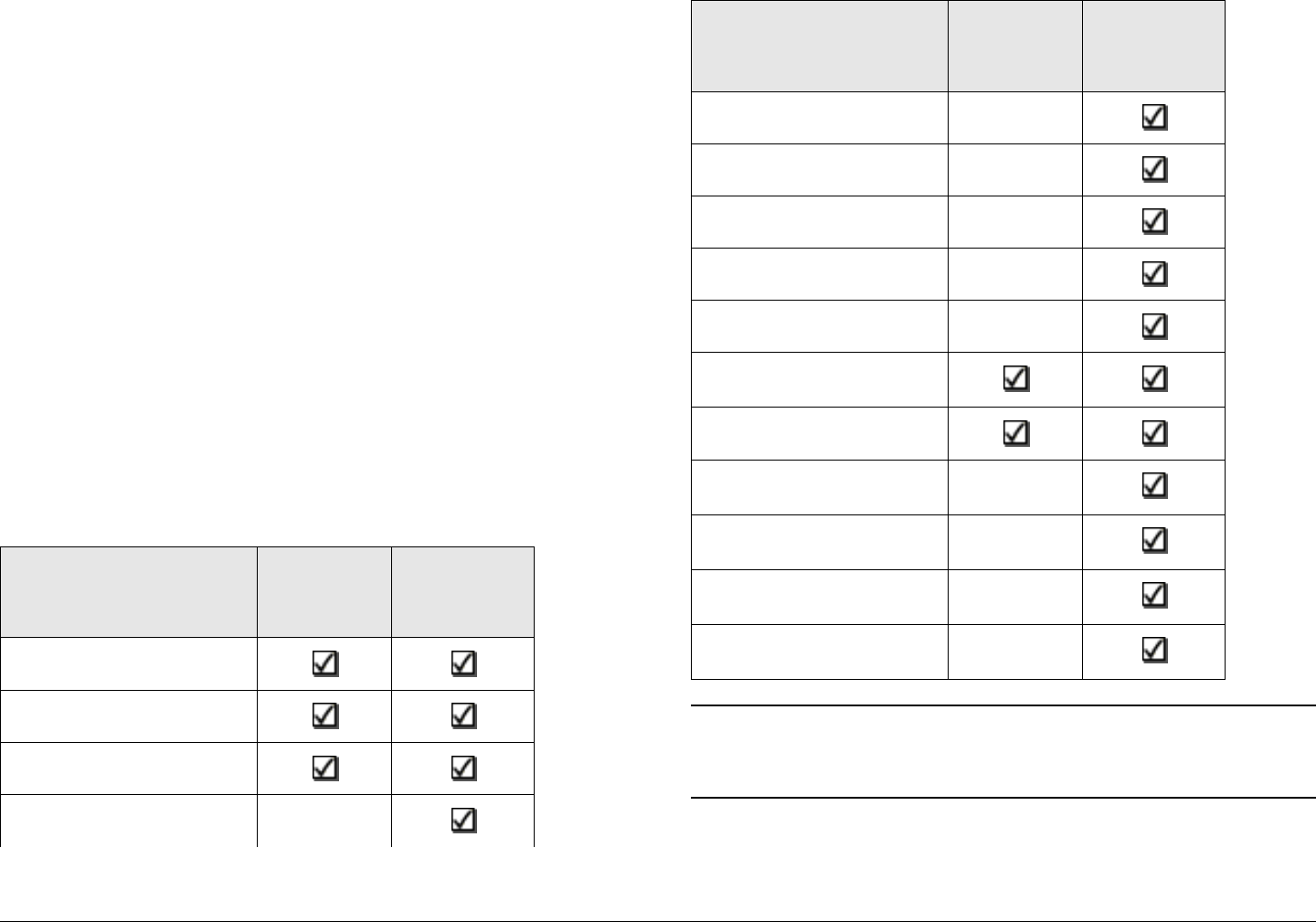
1.3 How It’s Organized
The manuals for the CodeRunner 2 are organized as follows:
Chapter Operator’s
Guide
Technical
Reference
Manual
Introduction
Product Description
Routine Operation
Advanced Operation
Note The Technical Reference Manual contains
everything in the Operator’s Guide, plus
additional technical content.
Installation
Troubleshooting
Repair
Replacement Parts
Theory of Operation
Appendix A - Channels
& Frequencies
Appendix B - Glossary
Appendix C - Module
Reference
Appendix D - Color Bar
Generator
Appendix E - Installing
Triax Connectors
Appendix F - Menu
Reference
Chapter Operator’s
Guide
Technical
Reference
Manual

Introduction 1-2CodeRunner 2 Operator’s Guide
1.4 Who It’s Written For
This manual is intended for use by personnel assigned to
operate the CodeRunner 2. Users of this manual should already
be familiar with basic concepts of radio, video and audio.
1.5 Related Documents
• MRC CodeRunner 2 Quick Reference Guide (part no.
400453)
• MRC CodeRunner 2 Technical Reference Manual (part
no. 400465)
• MRC CodeRunner 2 Helicopter Remote Control (part no.
400461)
1.6 Ordering documentation
Any of the above manuals may be ordered by contacting MRC
Customer Service:
Business Hours: Monday - Friday
8:00 AM - 7:00PM Eastern Time (US)
(0800 - 1900 hrs US ET)
Telephone: 800-490-5700
978-671-5700
Fax: 978-671-5800
When contacting Customer Service, please have the following
information available:
• Model number and serial number of the unit. This is
located in two places:
- label on the rear panel
- label inside the front panel.
• Approximate purchase date.
• Firmware revision, found in two places:
- displays on screen at startup
- label inside the front panel.
1.7 Calling for Service
MRC Technical Support is available 24 hours a day, 7 days a
week. During regular business hours you can reach our expert
staff directly. After hours, your call will be forwarded to the on-call
technical support specialist.
Business Hours: Monday
8:00 AM - 5:00PM Eastern Time (US)
(0800 - 1700 hrs US ET)
Tuesday - Friday
8:00 AM - 7:00PM Eastern Time (US)
(0800 - 1900 hrs US ET)
Telephone: 800-490-5700
978-671-5700
Fax: 978-671-5800
Email: support@mrcbroadcast.com
When contacting Technical Support, please have the following

Introduction 1-3CodeRunner 2 Operator’s Guide
information available:
• Model number and serial number of the unit. This is
located in two places:
- on a label on the rear panel
- on a label inside the front panel.
• Approximate purchase date.
• Firmware revision, found in two places:
- displays on screen at startup
- on a label inside the front panel.

Introduction 1-4CodeRunner 2 Operator’s Guide
This page intentionally left blank.

2
Product Description 2-1CodeRunner 2 Operator’s Guide/Tech Ref Manual
ProductDescription
2.1 Chapter Overview
This chapter provides a overall description of the product, its
components, and its capabilities.
Here are the topics covered:
Topic Page
System Description 2-1
System Components 2-3
Operating Controls 2-4
External Connectors 2-5
IDU/ODU (RFU)
Interconnection
2-7
System Configurations 2-8
Single Band/Dual
Antenna Configuration
2-8
Dual Band Non-
Simultaneous
Transmitting
2-9
Dual Band Simultaneous
Transmitting
2-10
For More Information 2-11
2.2 System Description
The MRC CodeRunner 2 transmitter is designed to be both an
analog and digital transmitter for ENG portable applications.
CodeRunner 2 can accommodate a variety of analog and digital
inputs, and apply either analog or digital modulation.
CodeRunner 2 is an integrated, flexible solution consisting of:
• A rack mounted Indoor Unit (IDU), typically mounted
inside an ENG vehicle.
• A mast mounted Outdoor Unit (ODU), also called the RF
Unit (RFU).
A typical installation is shown in Figure 2-1.
PowerOptionsThe CodeRunner 2 can be operated from
115 V / 220 V AC mains power, or from 18-36 V DC vehicle
power. Power is supplied to the IDU, which in turn powers the
ODU via the cable harness between them.
Analog/DigitalOptionsThe CodeRunner 2 is digital-ready,
which means it can be ordered and installed as a full-featured
analog radio. Then later, it can be upgraded just by adding the
digital MPEG/COFDM Module.
Band&FrequencyOptionsThe CodeRunner 2 is designed to
cover the bands below. It can be ordered as a single-band unit or
in a dual-band configuration to cover any two of these bands.
• 2-3 GHz
• 6-7 GHz
• 12-13 GHz
Band and frequency information is stored in the ODU, which
means switching bands after installation is very simple: just plug
in the RFU for the new band, and the IDU will automatically
configure itself for the new band.

Product Description 2-2CodeRunner 2 Operator’s Guide/Tech Ref Manual
Within these bands, channels can be preprogrammed at the
factory to match either the US broadcast channel plan, or a plan
specified by the customer. Channel frequencies can be
reprogrammed in the field using the keypad and display on the
IDU.
ColorBarGeneratorOptionsFor analog operation, an
optional analog color bar generator is available, either at time of
purchase or for later upgrade in the field. The digital MPEG/
COFDM Module has a built-in digital color bar generator. Either
the analog or digital generators are field configurable for
functions such as auto-standby (mute the transmitter on loss of
video) and auto-generate (provide tones and bars on loss of
video).
ConnectionOptionsThe CodeRunner 2 is designed to make
upgrading from an older radio as painless as possible. The IDU
and ODU can be ordered with a variety of connectors to plug into
an existing wiring harness. The connectors available for the
cable harness between the IDU and ODU are:
•Triax
• Type ‘N’
•TNC
The ODU comes with a standard Type N connector for the
antenna connection.
AntennaOptionsThe CodeRunner 2 is fully compatible with a
variety of antennas, including:
• MRC ProStar, models
- 2A20 and 2A20SS (2 GHz)
- 7A30 and 7A30SS (7 GHz)
- 2A20/7A30 (dual band 2 & 7 GHz)
- 2A20/7A30SS (dual band 2 & 7 GHz, solid state
switching)
• MRC Ellipse 2000
• MRC OmniPole Omnidirectional
Switching functions for band and antenna polarization are
controlled from the front panel of the IDU.
If your installation involves more than one antenna, this can be
easily accommodated by using the MRC RF Switch. The RF
Switch is also controlled from the front panel of the IDU.
Figure 2-1: Typical CodeRunner 2 System
Antenna
Outdoor Unit (ODU)
Conduit (Nycoil)
Indoor Unit (IDU)
(inside vehicle)
Pan & Tilt Assembly

Product Description 2-3CodeRunner 2 Operator’s Guide/Tech Ref Manual
2.3 System Components
An MRC CodeRunner 2 system is made up of the following
components:
• A rack mounted Indoor Unit (IDU), typically mounted
inside an ENG vehicle.
• A mast mounted Outdoor Unit (ODU), also called the RF
Unit (RFU).
A typical system is shown in Figure 2-2.
The IDU contains the baseband circuitry, power supply, and
control modules. It accepts a variety of audio and video inputs,
both digital and analog, and generates a 70 MHz IF output. It
also accepts IF input from external modulators.
For digital operation, the IDU can be equipped with an optional
internal MPEG/COFDM Module. Or, the IDU can be used with
existing external digital encoders and modulators.
The ODU contains the upconvertors and power amplifier. The
ODU accepts the 70 MHz IF, converts it to the operating band
chosen, and amplifies it.
Every installation will include an antenna, either directional or
omnidirectional, or both. An MRC RF Switch can be mounted up
on the mast to select the antenna desired.
When using a mast mounted antenna, a Nycoil conduit sheath
covers the wiring harness between the IDU to the ODU. This
harness carries the power, IF, and antenna band and polarization
switching. Addition wiring is added for controlling the pan & tilt
mechanism, and for implementing additional functions such as
off-air monitors, mast lights, etc.
Figure 2-2: CodeRunner 2 System Components
RF Switch
Directional Antenna
(MRC 2A20, 7A30, Ellipse 2000)
Pan & Tilt Assembly
Outdoor RF Unit
(Upconvertor,
Power Amp)
Conduit (Nycoil)
OmniPole Antenna
CodeRunner 2 Indoor Unit
(Baseband, Audio/Video Modules)
External
Modulator
(Optional)
External
Encoder
(Optional)
Internal
MPEG Encoder &
COFDM Modulator
(Optional)
Product Description 2-4CodeRunner 2 Operator’s Guide/Tech Ref Manual
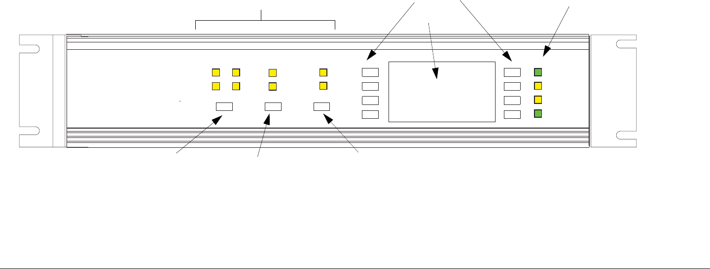
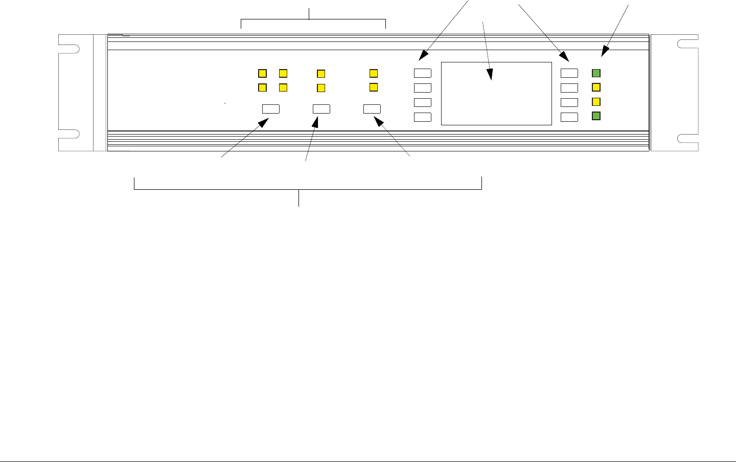
2.4 Operating Controls
All controls are on the front panel of the IDU. There are no
controls or adjustments on the ODU (RFU).
All transmitter functions are controlled using an LCD display with
8 button keypad, and a set of 3 function switches. See Figure 2-3
on page 2-4.
The LCD display and keypad are used to toggle through control
and diagnostic menus for both the IDU and ODU.
Functions switches directly control antenna polarization, band
selection, and antenna selection.
Figure 2-3: Front Panel Controls
POWER
IDU ALARM
PA ON
RFU ALARM
BAND
SELECT
POLARIZATION
ANT 1
ANT 2
RFU 1
RFU 2
LC
RC
H
V
TRANSMITTER
MRC CODERUNNER 2-C/M
Function Buttons
Display
Keypad LED Indicators
Polarization Select Band Select Antenna Select
Product Description 2-5CodeRunner 2 Operator’s Guide/Tech Ref Manual
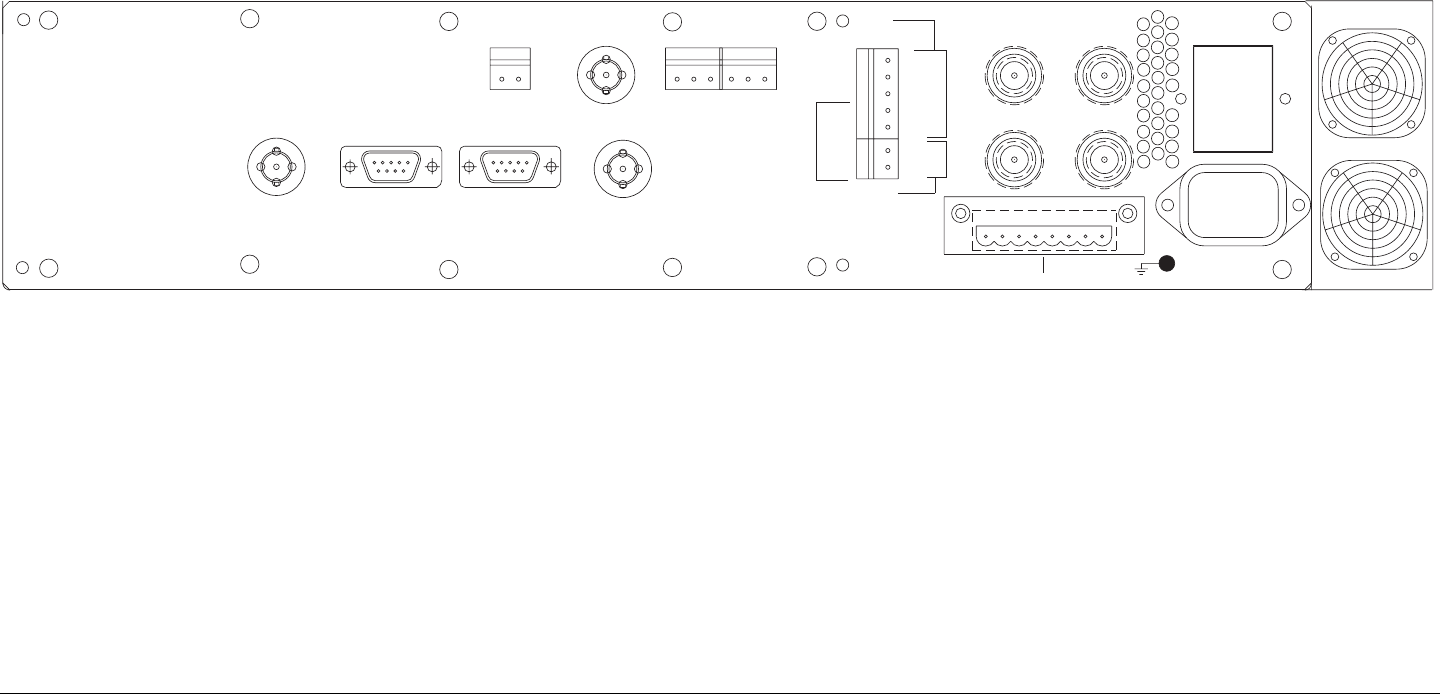
2.5 External Connectors
All transmitter connections are made at the rear panel of the
IDU. The panel layout is shown in Figure 2-4.
Brief descriptions of the connections are found in Table 2-1. For
more detailed information, see the MRCCodeRunner2
TechnicalReferenceManual.
Figure 2-4: Rear Panel Connectors
BB IN
VIDEO IN
AUX RS232 BAND 2
ANT 2
+
RFU 2
RFU 1
~POWER
50-60 Hz
120-240V AC
2A - 120V AC
1A - 240V AC
FEED/
RELAY
POWER
HOST RS232 V MON. OUT
AUDIO 1AUDIO 2
IF INDATA IN PAN/TILT
FEED
MOD SUM ALM
POWER
V
H
LCP
GND
+24V
GND
RF UNIT
PWR OUT--++--++
RFU1 RFU2
RF
SWITCH

Product Description 2-6CodeRunner 2 Operator’s Guide/Tech Ref Manual
Table 2-1: IDU Rear Panel Connections
Connector Function
Summary Alarm Input Alarm input from external device such as
a modulator.
Analog Video Input Input for analog video.
Baseband Input Input from external baseband source.
Audio Input Line level analog audio input.
Data In/Out Can be used as either input or output for
digital video (DVB-ASI). Configured via
menus on front panel display.
IF Input IF input from external modulator
RF Outputs 1 and 2 • IF + DC Power + Control to RFU
(Triax Connector option)
• IF + Control to RFU (Type ‘N’ and
TNC connector option)
Pan & Tilt Control Not Used
Power Input Supply power to CodeRunner 2 system
(both IDU and RFU).
Grounding Lug Connection to chassis ground
RFU Power Output DC Power to RFU 1 and RFU 2 (only
present with Type ‘N’ and TNC connection
options).
Antenna Control
• FEED POWER
• FEED/RELAY
POWER
• Control for antenna polarization,
antenna band, and RF Switch.
• Power for antenna and RF Switch.
Video Monitor Output Analog video output to monitor the analog
Color Bar Generator. Does not contain
program video.
Host Serial Port RS-232 data
Auxiliary Serial Port RS-232 data
Table 2-1: IDU Rear Panel Connections (Continued)
Connector Function

Product Description 2-7CodeRunner 2 Operator’s Guide/Tech Ref Manual
2.6 IDU/ODU (RFU) Interconnection
The IDU connects to the Outdoor RF Unit through a wiring
harness inside a coiled conduit (Nycoil) sheathing.
The wiring harness will contain power, RF and control for all
components mounted at the top of the mast. The harness is
specific to a particular installation, and is designed to support all
the desired functions. These functions would typically include:
• IF, control, and alarms between the IDU and ODU.
• DC Power to the ODU.
• Power and control for an RF Switch to select antennas.
• Power and control for antenna switching functions (band,
polarization).
• Power for mast top lights.
• Control and power for the Pan and Tilt assembly.
• RF and control for an off-air antenna.
• Mast top safety sensors for proximity, high voltage, etc.
Since each installation is different, the harness must be specified
for each installation. The harness can be supplied by MRC, or is
often supplied by the van integrator.
For more detailed information, see the MRCCodeRunner2
TechnicalReferenceManual.
Product Description 2-8CodeRunner 2 Operator’s Guide/Tech Ref Manual
2.7 System Configurations
The CodeRunner allows several antenna configurations for
transmitting with either an OmniPole or directional antenna, in
either single-band or dual-band operation.
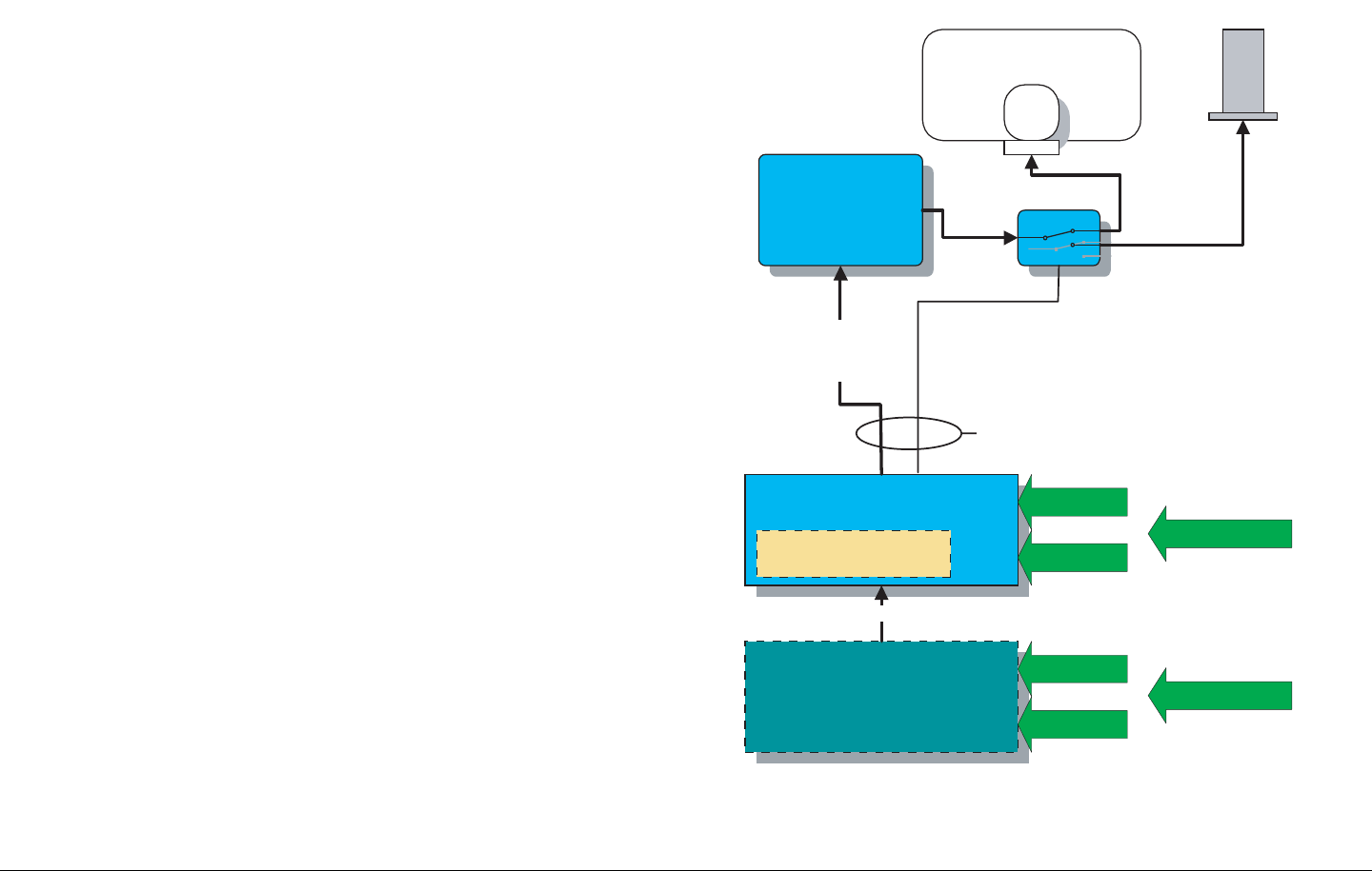
2.7.1 Single Band/Dual Antenna Configuration
Figure 2-6 shows the antenna configuration for single-band
transmitting using one Indoor Unit with one RF Unit.
The RFU could be operating on the 2 GHz, 7 GHz, or 13 GHz
bands.
In addition, an RF Switch allows switching between an OmniPole
and a directional antenna.
Figure 2-5: Single Band Operation with 2 Antennas
MRC RF SWITCH
OmnPole
CodeRunner 2
RFU
CodeRunner 2
IDU
70 Mhz
IF
+ CONTROL
+ POWER
COFDM
MODULATOR
ASI
ANTENNA
SWITCH
POWER &
CONTROL
NYCOIL CONDUIT
MPEG Encoder &
COFDM Modulator
MPEG ENCODER/
Directional
2 Analog Audio
2 Analog Audio
Analog Video
Analog Video
Digital Video + Audio SDI
DVB/ASI
Digital Video + Audio SDI
DVB/ASI
Product Description 2-9CodeRunner 2 Operator’s Guide/Tech Ref Manual
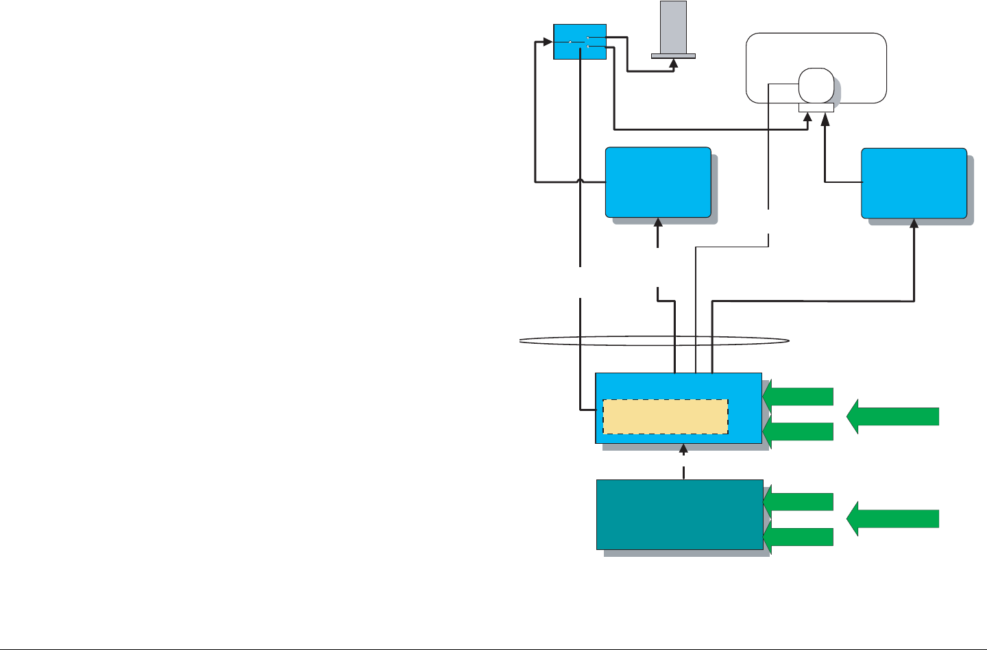
2.7.2 Dual Band Non-Simultaneous Transmitting
Figure 2-6 shows the antenna configuration for non-
simultaneous transmitting using one Indoor Unit with two RF
Units.
In this example the RFUs are operating on 2 GHz and 7 GHz
bands, but the 13 GHz band is also available as one of the two
bands.
In addition, an RF Switch allows switching one of the RF Units
between an OmniPole and a directional antenna.
Figure 2-6: Dual Band, Non-Simultaneous Operation
RF SWITCH OmniPole
RFU
1.99-2.5 GHz
CodeRunner 2
70 Mhz
IF +
CONTROL +
POWER
70 Mhz
IF +
CONTROL +
POWER
70 MHZ IF
RFU
6.4-7.1 GHz
MPEG
ENCODER / COFDM
MODULATOR
ANTENNA
SWITCH
POWER/CONTROL
POLARIZATION
SWITCH
MPEG Encoder &
COFDM Modulator
Directional
NYCOIL CONDUIT
2 Analog Audio
2 Analog Audio
Analog Video
Analog Video
Digital Video + Audio SDI
DVB/ASI
Digital Video + Audio SDI
DVB/ASI
Product Description 2-10CodeRunner 2 Operator’s Guide/Tech Ref Manual
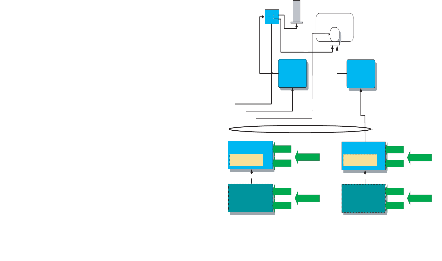
2.7.3 Dual Band Simultaneous Transmitting
Figure 2-7 shows the antenna configuration for simultaneous
transmitting using two Indoor Units with two RF Units.
In this example the RFUs are operating on 2 GHz and 7 GHz
bands, but the 13 GHz band is also available as one of the two
bands.
In addition, an RF Switch allows switching one of the RF Units
between an OmniPole and a directional antenna.
Figure 2-7: Dual Band Simultaneous Operation
OmniPole
RFU
1.99-2.5 GHz
70 Mhz
IF +
POWER +
CONTROL
70 Mhz
IF +
POWER +
CONTROL
RFU
6.4-7.1 GHz
CodeRunner 2 IDU
70 MHZ IF
ENCODER / COFDM
MODULATOR
NYCOIL CONDUIT
POLARIZATION
SWITCH
CodeRunner 2 IDU
70 MHZ IF
MPEG
ENCODER / COFDM
MODULATOR
MPEG Encoder &
COFDM Modulator
MPEG Encoder &
COFDM Modulator
Directional
MPEG
RF SWITCH
2 Analog Audio
2 Analog Audio
Analog Video
Analog Video
Digital Video + Audio SDI
DVB/ASI
Digital Video + Audio SDI
DVB/ASI
2 Analog Audio
2 Analog Audio
Analog Video
Analog Video
Digital Video + Audio SDI
DVB/ASI
Digital Video + Audio SDI
DVB/ASI
ANTENNA SWITCH
POWER & CONTROL

Product Description 2-11CodeRunner 2 Operator’s Guide/Tech Ref Manual
2.8 For More Information
More detailed technical information about the CodeRunner 2 can
be found in the CodeRunner2TechnicalReferenceManual.
Specific topics are listed below:
Topic Chapter
IDU
Block Diagram Theory of Operation
Operating Controls Basic Operation
Screen Menus Advanced Operation
Rear Panel Connections Installation
Supported Repairs Repair
Repair Parts Replacement Parts
ODU
Block Diagram Theory of Operation
Connections Installation
Supported Repairs Repair

Product Description 2-12CodeRunner 2 Operator’s Guide/Tech Ref Manual
This page intentionally left blank.

3
Routine Operation 3-1CodeRunner 2 Operator’s Guide/Tech Ref Manual
RoutineOperation
3.1 Chapter Overview
This chapter provides basic information that will enable you to
operate your CodeRunner 2. More detailed information can be
found in the CodeRunner 2 Technical Reference Manual.
Here are the topics covered:
Topic Page
Overview of Controls 3-1
Function Buttons 3-1
Status LEDs 3-3
Display and Keypad 3-5
Frequently Performed Tasks 3-7
Menu Maps 3-10
3.2 Overview of Controls
The CodeRunner 2 front panel has the following controls and
indicators:
• Function Buttons
•Status LEDs
• Display and Keypad
Each of these is described in more detail in the sections that
follow. See Figure 3-1 on page 3-4 for the layout of the front
panel.
3.3 Function Buttons
The CodeRunner 2 provides three function buttons that control
three specific functions:
• Polarization Select
• Band Select
• Antenna Select
Each also has an LED which illuminates to show which choice is
currently selected. See Figure 3-1 on page 3-4.
AutomaticLockoutTo prevent accidental activation, all
function buttons and keypad keys become locked out after
approximately 30 seconds of inactivity. This time period is fixed
and not selectable by the user.
This time period is also independent of the Backlight Delay
setting, which controls how long the display backlight stays on
before automatically turning off. The Backlight Delay is set under
the Configuration menu.
To unlock the buttons and keys, press any button or key once.
Then press the desired button or key to make your selection.

Routine Operation 3-2CodeRunner 2 Operator’s Guide/Tech Ref Manual
3.3.1 Polarization Select
If your installation includes an antenna with selectable
polarization (such as the MRC 2A20/7A30 or Ellipse 2000), this
function button will allow you to make that selection.
Pressing the Polarization Select button toggles through the four
choices in sequence. As each choice is selected, the
corresponding LED illuminates. The four choices are:
• H (Horizontal Polarization)
• V (Vertical Polarization)
• RC (Right Circular Polarization)
• LC (Left Circular Polarization)
3.3.2 Band Select
If your CodeRunner 2 has dual band capability, and your
installation includes more than one RF Unit (RFU), this function
button allows you to select which RFU is active.
Pressing the Band Select button toggles back and forth between
the two choices. As each choice is selected, the corresponding
LED illuminates. The two choices are:
•RFU1
•RFU2
The IDU will automatically detect which RFU is on which band,
and configure the IDU menus to match that band.
3.3.3 Antenna Select
If your installation includes more than one antenna (such as an
MRC OmniPole and an MRC Ellipse 2000) and an MRC RF
Switch, this function button will allow you to select which antenna
is in use.
Pressing the Antenna Select button toggles back and forth
between the two choices. As each choice is selected, the
corresponding LED illuminates. The two choices are:
• ANT1 (Antenna 1)
• ANT2 (Antenna 2)

Routine Operation 3-3CodeRunner 2 Operator’s Guide/Tech Ref Manual
3.4 Status LEDs
The CodeRunner 2 has four Status LEDs to keep you informed
about the status of the system (See Figure 3-1 on page 3-4).
Those LEDs are described in Table 3-1.
Table 3-1: Status LEDs
Panel
Label Description Color
POWER Indicates IDU is powered
up.
Green
IDU Alarm Fault condition in Indoor
Unit (IDU).
Yellow
RFU Alarm Fault condition in RF Unit
(ODU).
Yellow
PA On Power Amplifier section of
RFU is powered up
(actively transmitting).
Green
Routine Operation 3-4CodeRunner 2 Operator’s Guide/Tech Ref Manual
Figure 3-1: Front Panel Controls
POWER
IDU ALARM
PA ON
RFU ALARM
BAND
SELECT
POLARIZATION
ANT 1
ANT 2
RFU 1
RFU 2
LC
RC
H
V
TRANSMITTER
MRC CODERUNNER 2-C/M
Function LEDs
Display
Keypad Status LEDs
Polarization Select Band Select Antenna Select
Function Buttons

Routine Operation 3-5CodeRunner 2 Operator’s Guide/Tech Ref Manual
3.5 Display and Keypad
The CodeRunner 2 has an LCD display and an 8-key keypad
(see Figure 3-1 on page 3-4). You will use the display and
keypad to set configurations, monitor status, and troubleshoot
problems.
Details of the individual menus are found in the CodeRunner2
TechnicalReferenceManual.
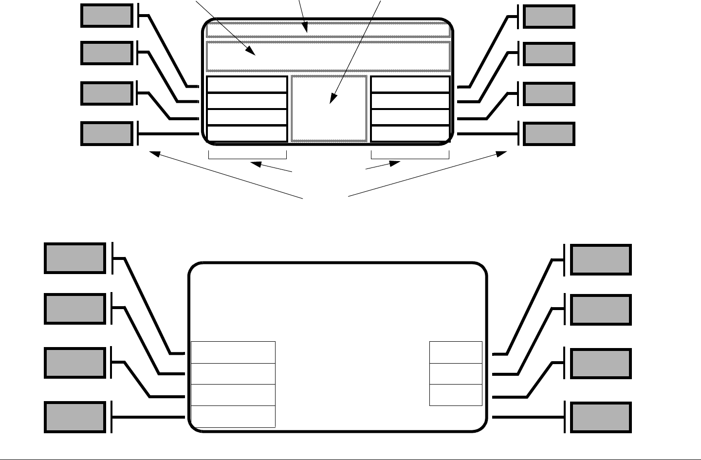
3.5.1 Display Layout
The display is organized into five areas that are used for specific
purposes (see Figure 3-2 on page 3-6):
HeadingAreaThis is generally used for the title of the current
menu screen, such as “Configuration Menu”. It is also
sometimes used for displaying data or status information when
the display is crowded.
MessageAreaThe Message Area is used for displaying alarm
and error messages, and for general status information.
StatusAreaThis area is used for displaying the current settings
for the available menu choices.
MenuAreasThere are two menu areas, one on the right of the
display and one on the left. Each can accommodate 4 menu
choices, which correspond to the four keys on each side of the
display.
3.5.2 Navigating using the display and keypad
MakingaSelectionThe eight keypad keys correspond to the
eight fields in the menu areas. To select an available menu item,
just press the key corresponding to that menu item.
• If you selected a menu, that menu will now appear on the
display.
• If you changed a setting, the Status Area will change to
show the new setting.
AccessingtheMainMenuThe most commonly used choices
and settings are available from the Main Screen. These are the
choices an operator might need while using the CodeRunner 2.
Choices and settings more typically performed by the technical
staff are all grouped in menus accessible only through the Main
Menu.
To access the Main menu from the Main Screen, press the Menu
key TWICE.
AutomaticLockoutTo prevent accidental activation, all
function buttons and keypad keys become locked out after
approximately 30 seconds of inactivity. This time period is fixed
and not selectable by the user.
This time period is also independent of the Backlight Delay
setting, which controls how long the display backlight stays on
before automatically turning off. The Backlight Delay is set under
the Configuration menu.
To unlock the buttons and keys, press any button or key once.
Then press the desired button or key to make your selection.
BacklightDelayThe display includes a backlight for easy
viewing in a variety of lighting conditions. The backlight can be
configured to remain on, or to automatically turn off after a time
delay. This Backlight Delay is set under the Configuration menu.
DefaulttoMainScreenTo help prevent accidental activation of
the keypad keys, the display will automatically default to the
Main Screen when the Backlight turns off. If the Backlight is
configured to remain on, the display continues to shown the last
screen used.
Routine Operation 3-6CodeRunner 2 Operator’s Guide/Tech Ref Manual
Figure 3-2: Display and Keypad Layout
Figure 3-3: Main Screen Display
Heading Area
Message
Area Status Area
Menu Areas
Keypad
Di/An ANALOG STDBY PA
Chnl 1 17M HI Hi/Lo
Offst 0 2 GHz Rem
Menu Pwr 0.0 dBm
CodeRunner.2 Rel.4.03
RFU1 Rev B

Routine Operation 3-7CodeRunner 2 Operator’s Guide/Tech Ref Manual
3.6 Frequently Performed Tasks
This chapter describes how to perform many common tasks with
the CodeRunner 2. Here are the tasks described:
Refer to the Main Screen display in Figure 3-3, and the menu
maps in Figure 3-4 and Figure 3-5 to follow along with these
instructions.
Topic Page
Turning the power ON and
OFF
3-7
Activating and deactivating
the transmitter
3-7
Switching between HI and
LOW power
3-7
Selecting Channel and
Offset
3-8
Switching between antennas 3-8
Switching antenna
polarization
3-8
Switching bands 3-8
Switching between Analog
and Digital modes
3-8
Setting for Remote
operation
3-9
3.6.1 Turning the power ON and OFF
1. Open the front panel of the Indoor Unit by loosening
the 2 large screws and letting the panel swing down.
2. Press the Power switch.
3. Close the front panel by swinging it up and tightening
the two screws.
3.6.2 Activating and deactivating the transmitter
1. Make sure the power to the CodeRunner 2 is on.
2. On the Main Screen,
-To activate the transmitter: press PA until the Status
Area displays XMIT.
-To deactivate the transmitter: press PA until the Status
Area displays STDBY.
3.6.3 Switching between HI and LOW power
1. Make sure the power to the CodeRunner 2 is on.
2. On the Main Screen,
- To switch the transmitter to High power: press Hi/Lo
until the Status Area displays High.
- To switch the transmitter to Low power: press Hi/Lo
until the Status Area displays LOW.

Routine Operation 3-8CodeRunner 2 Operator’s Guide/Tech Ref Manual
3.6.4 Selecting Channel and Offset
1. Make sure the power to the CodeRunner 2 is on.
2. On the Main Screen,
- To change the channel on which the radio will
transmit: press Chnl until the Status Area displays the
channel desired.
- To change the frequency offset above or below the
selected channel: press Offst until the Status Area
displays the offset desired.
3.6.5 Switching between antennas
1. Make sure the power to the CodeRunner 2 is on.
2. Press the Antenna Select function button until the LED
illuminates next to the desired antenna.
3.6.6 Switching antenna polarization
1. Make sure the power to the CodeRunner 2 is on.
2. Press the Polarization Select function button until the
LED illuminates next to the desired polarization.
3.6.7 Switching bands
Which band(s) the CodeRunner 2 operates on is set by the
RFU(s) connected to the IDU. Switching bands in accomplished
by switching between RFUs:
1. Make sure the power to the CodeRunner 2 is on.
2. Press the Band Select function button until the LED
illuminates next to the desired RFU covering the
desired band.
3.6.8 Switching between Analog and Digital
modes
1. Make sure the power to the CodeRunner 2 is on.
2. On the Main Screen,
- To switch the transmitter to Digital mode: press
Di/An until the Status Area displays DIGITAL.
- To switch the transmitter to Analog mode: press
Di/An until the Status Area displays ANALOG.

Routine Operation 3-9CodeRunner 2 Operator’s Guide/Tech Ref Manual
3.6.9 Setting for Remote operation
The MRC Remote Control Panel allows control of the
CodeRunner 2 from the passenger compartment regardless of
where in the vehicle or aircraft the CR2 is physically located.
The Remote uses vehicle or aircraft power, and communicates
with the IDU via an RS-232 serial interface.
To set up the CR2 to operate with the Remote Control, perform
the following steps on the IDU:
1. Enable remote control operation.
- Make sure the CodeRunner 2 has power and is turned
on.
- Make sure the Remote Control Panel has power, is
turned on, and is connected to IDU.
- On the Main Screen, press Menu twice to access the
Main Menu.
- On the Main Menu screen, select Remote Menu.
- On the Remote Control Menu screen, press Rmt
Cntrl until the Status Area displays ENABLED.
If there is a problem with the communication between
the Remote Control and the IDU, the IDU Alarm LED
will illuminate, and the screen will display Serial
Comm Failure. See the “Troubleshooting” chapter
of the CR2TechnicalReferenceManual for help
resolving the problem.
2. Turn off the Modem in the Remote Control menu.
- On the Remote Control Menu screen, press Modem
until the Status Area displays OFF.
3. Set both Transmit and Receive baud rates to 9600.
- On the Remote Control Menu screen, press TxBaud
until the Status Area displays 9600.
- On the Remote Control Menu screen, press RxBaud
until the Status Area displays 9600.
4. Set Remote Control to Remote.
- On the Remote Control Menu screen, select Menu.
- On the Main Menu screen, select Main Screen.
- On the Main Screen, press Rem until the Status Area
shows RMT.
Once the radio is set to RMT, the front panel controls will be partly
disabled:
• Navigation from one menu screen to another will work
normally.
• Any keys that make menu selections or change settings
will be disabled.
• The Function Buttons will be disabled.
All these functions will be controlled by the Remote Control
Panel.
To restore normal front panel operation:
- On the Main Screen, press Rem until the Status Area
displays LCL.

Routine Operation 3-10CodeRunner 2 Operator’s Guide/Tech Ref Manual
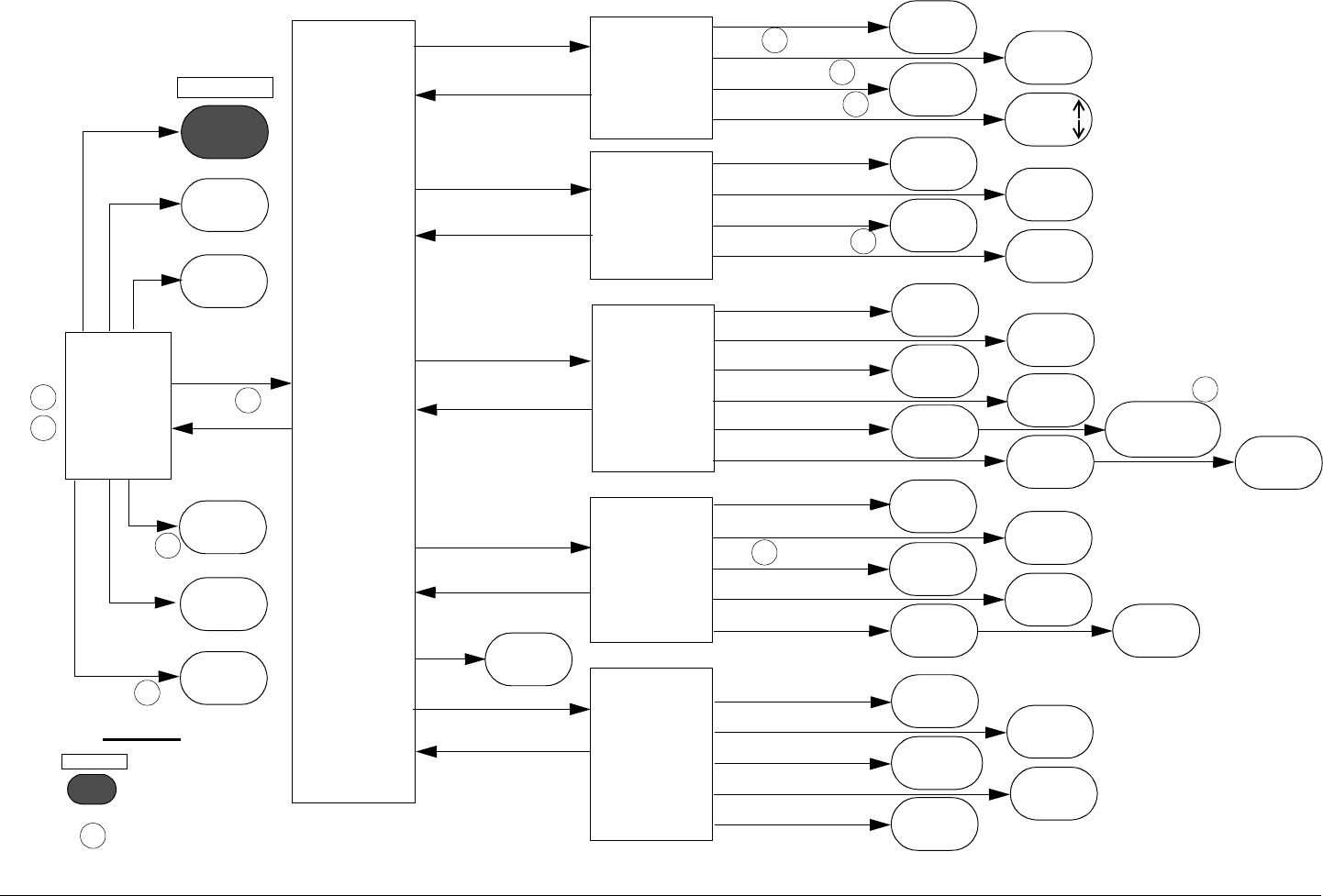
3.7 Menu Maps
Following are one-page menu maps to help you navigate
through the many features and capabilities of your
CodeRunner 2.
For more detail about any of these menus or the settings
available, see the CodeRunner2TechnicalReference
Manual, in the chapter “Advanced Operation”.
Routine Operation 3-11CodeRunner 2 Operator’s Guide/Tech Ref Manual
Figure 3-4: Analog Menu Map
Configura-
tion Menu
Main
Screen Main
Menu
Remote
Control
Menu
Indoor
Unit
Menu
RF Unit
Menu
Modify
Channel
Plan
Config Menu
Menu
Remote Menu
IDU Menu
RF Unit
Mod CP
Menu
Main Menu
Main Menu
Main
Menu
Main
Screen
CP Sel
XMIT/
STDBY
(displays
DISABLED
Contrast
PA
BkltDly
PAAdjust
Contrast Contrast
ON/30/60/
90sec/
3/5min
TxBaud
RxBaud
RmtCntrl
Modem ON/
OFF
ENABLED/
DISABLED
150/300/
1200/4800/
9600/19200 150/300/
1200/4800/
9600/19200
Pwr
PA
Channel
Offset
+/-/0/
++
Channel
Offset
Save
PwrSupply
(saves
changes)
HI/
LOW STDBY/
XMIT
1/2/3...
10
Rst Min/Max
(resets
min/max)
<- / ->
+ / -
(changes
digits)
(selects
digits)
1/2/3...
15 +/-/0/
++
(displays
voltages)
Di/An
Chnl
Offst
PA
Hi/Lo
ANALOG
1/2/
3...10
+/-/0/
++
STDBY/
XMIT
HI/
LOW
Digital
Video Mod
Audio Mod
OFDM Config
Col Bar Gen
Pwr Supply
(displays
STATUS:OK
(displays
STATUS:OK (displays
INACTIVE)
(displays
status) Mode
DISABLED/
AUTOSTDBY/
TONES+BARS/
AUTOGEN
Rst Min/Max
(resets
min/max)
(displays
voltages
(auto-adjusts
PA voltage)
= See Notes
1
= Choice made
Digital
Legend
14.5 /
17 MHz
1
2
3
3
3
3
4
4
LCL/
RMT
Rem 5
5
6
Routine Operation 3-12CodeRunner 2 Operator’s Guide/Tech Ref Manual
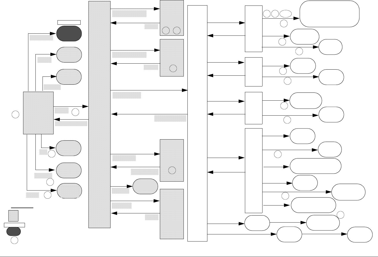
Figure 3-5: Digital Menu Map
Configu-
ration
Menu
Main
Screen Main
Menu
Remote
Control
Menu
Indoor
Unit
Menu
RF Unit
Menu
Modify
Channel
Plan
Config Menu
Menu
Remote Menu
IDU Menu
RF Unit
Mod CP
Menu
Main Menu
Main Menu
Main
Menu
Main Screen
CP Sel
1/2/3/4,
..15 dB/
AUTO
Di/An
Chnl
Offst
PA
Hi/Lo
DIGITAL
1/2/
3...10
+/-/0/
++
STDBY/
XMIT
HI/
LOW
Digital
Video Mod
Audio Mod
OFDM Config
Col Bar Gen
Pwr Supply
16QAM/
64QAM/
QPSK
(displays
status) Mode
OFF/
ON/
AUTOGEN
Rst Min/Max
(resets
min/max)
(displays
voltages)
Digital
Menu
Mode
Attn
Modulation
Video
Modu-
lator
Menu
Input
Chroma
SDI/
ANALOG 4:2:0/
4:2:2
Audio
Modu-
lator
Menu
Input
Config
OFF/TONE/
SDI/
EMBEDDED
MONO/
STEREO
OFDM
Config-
uration
Menu
BW
INTERNAL BASEBAND
INTERNAL COFDM ONLY
EXTERNAL IF
INTERNAL MPEG/COFDM
INTERNAL DVB-S
Mod
FEC
1/2 2/3 3/4
5/6 7/8
CW Tone ON/OFF
GI 1/32 1/16
1/8 1/4
6/7/8
MHz 16QAM/
64QAM/
QPSK
1/2/3/4
,..15 dB/
AUTO
Attn
= Same as
Analog Map
= See Notes
1
1
1
= Choice made
Digital
Legend
1
2
1
9
9
9
9
2
2
3
4
14.5 /
17 MHz
5
5
5
IDU Menu
IDU Menu
IDU Menu
IDU Menu
LCL/
RMT
Rem 6
= Same as
Analog Map
6
7
8
910

Routine Operation 3-13CodeRunner 2 Operator’s Guide/Tech Ref Manual
Notes - Menu Maps
Analog
1. To access the Main Menu, press the Menu key twice.
2. To prevent accidental activation, all menu keys and
function buttons will become locked out after 30 sec.
of inactivity. To unlock, press the first desired key or
button twice.
3. PA Adjust only operates when PA is set to XMIT.
4. BkltDly (Backlight Delay) also controls whether the
display defaults to the Main Screen or not.
If BkltDly is set to ON
- backlight stays on continuously
AND
- display does not default to the Main Screen
Any other setting of BkltDly will cause the backlight
to turn off and the display to default to the Main Screen
after the selected period of time.
5. REM menu option only appears on Main Screen if
RmtCntrl is set to ENABLED.
6. Col Bar Gen controls the Analog Color Bar
Generator.
Digital
1. HI/LOW power selection only operates if
- Attn (Attenuation) is set to AUTO
AND
- Mode is set to
INTERNAL MPEG/COFDM
2. The menu options for modulation are only available
when
- Mode is set to
INTERNAL MPEG/COFDM
Otherwise the menu options will not appear. Selecting
any of the modulation menus will cause the display to
show Disabled or Inactive.
3. To access the Main Menu, press the Menu key twice.
4. To prevent accidental activation, all menu keys and
function buttons will become locked out after 30 sec.
of inactivity. To unlock, press the first desired key or
button twice.
5. PA Adjust only operates when PA is set to XMIT.
6. REM menu option only appears on Main Screen if
RmtCntrl is set to ENABLED.

Routine Operation 3-14CodeRunner 2 Operator’s Guide/Tech Ref Manual
7. BkltDly (Backlight Delay) also controls whether the
display defaults to the Main Screen or not.
If BkltDly is set to ON
- backlight stays on continuously
AND
- display does not default to the Main Screen
Any other setting of BkltDly will cause the backlight
to turn off and the display to default to the Main Screen
after the selected period of time.
8. Col Bar Gen controls the Digital Color Bar
Generator.
9. The menu choices in the Video Modulator and Audio
Modulator menus only appear if Mode is set to
INTERNAL MPEG/COFDM.
10. The only options that are implemented and functional
are:
- INTERNAL MPEG/COFDM
- EXTERNAL IF
The remaining options:
- INTERNAL BASEBAND
- INTERNAL COFDM ONLY
- INTERNAL DVB-S
are not implemented and are not functional.

A
Channels & Frequencies A-1CodeRunner 2 Operator’s Guide/Tech Ref Manual
Channels&
Frequencies
A.1 Appendix Overview
This Appendix presents the channels and frequencies that were
programmed into your CR2 at the factory. It also provides the
frequencies set by the latest US frequency reallocation plan.
Here are the topics covered:
A.2 Initial Factory Presets
This section lists the channels and frequencies for each RF band
covered by the CodeRunner 2. These frequencies are preset at
the factory, but can be modified using the Channel Plan Menu,
found under the “Mod CP” option on the Main Menu screen.
See the “Advanced Operation” chapter of the CR2Technical
ReferenceManual.
Note These frequency settings should only be changed
by qualified technical personnel.
Topic Page
Initial Factory Presets A-1
US 12 MHz Channel Plan A-6

Channels & Frequencies A-2CodeRunner 2 Operator’s Guide/Tech Ref Manual
Table A-1: 2 GHz RF Channel Guide (U.S. Broadcast) - 17 MHz Channel Plan
Channel (-) Offset (MHz) (0) Center (MHz) (+) Offset (MHz) (++) Offset (MHz)
-4.25MHz 17.0MHzspacing+4.25MHz
1 1994.75 1999.0 2003.25 00000.000
2 2012.25 2016.5 2020.75 00000.000
3 2029.25 2033.5 2037.75 00000.000
4 2046.25 2050.5 2054.75 00000.000
5 2063.25 2067.5 2071.75 00000.000
6 2080.25 2084.5 2088.75 00000.000
7 2097.25 2101.5 2105.75 00000.000
8 2454.25 2458.5 2462.75 00000.000
9 2471.25 2475.5 2479.75 00000.000
10 2487.75 2492.0 2496.25 00000.000
11 00000.000 00000.000 00000.000 00000.000
12 00000.000 00000.000 00000.000 00000.000
13 00000.000 00000.000 00000.000 00000.000
14 00000.000 00000.000 00000.000 00000.000
15 00000.000 00000.000 00000.000 00000.000

Channels & Frequencies A-3CodeRunner 2 Operator’s Guide/Tech Ref Manual
Note As of the publication of this manual, the 14.5 MHz channel plan was not approved for use in the US.
Table A-2: 2 GHz RF Channel Guide (U.S. Broadcast) - 14.5 MHz Channel Plan
Channel (-) Offset (MHz) (0) Center (MHz) (+) Offset (MHz) (++) Offset (MHz)
-4.25MHz 14.5MHzspacing+4.25MHz
1 2012.00 2015.50 2019.00 00000.000
2 2026.75 2030.25 2033.75 00000.000
3 2041.25 2044.75 2048.25 00000.000
4 2055.75 2059.25 2062.75 00000.000
5 2070.25 2073.75 2077.25 00000.000
6 2084.75 2088.25 2091.75 00000.000
7 2099.25 2102.75 2106.25 00000.000
8 2454.25 2458.50 2462.75 00000.000
9 2471.25 2475.50 2479.75 00000.000
10 2487.75 2492.00 2496.25 00000.000
11 00000.000 00000.000 00000.000 00000.000
12 00000.000 00000.000 00000.000 00000.000
13 00000.000 00000.000 00000.000 00000.000
14 00000.000 00000.000 00000.000 00000.000
15 00000.000 00000.000 00000.000 00000.000

Channels & Frequencies A-4CodeRunner 2 Operator’s Guide/Tech Ref Manual
Table A-3: 6/7 GHz RF Channel Guide (U.S. Broadcast)
Channel (-) Offset (MHz) (0) Center (MHz) (+) Offset (MHz) (++) Offset (MHz)
-6.25MHz 25.0MHzspacing+6.25MHz
1 6881.25 6887.50 6893.75 00000.000
2 6906.25 6912.50 6918.75 00000.000
3 6913.25 6937.50 6943.75 00000.000
4 6956.25 6962.50 6968.75 00000.000
5 6981.25 6987.50 6993.75 00000.000
6 7006.25 7012.50 7018.75 00000.000
7 7031.25 7037.50 7043.75 00000.000
8 7056.25 7062.50 7068.75 00000.000
9 7081.25 7087.50 7093.75 00000.000
10 7106.25 7112.50 7118.75 00000.000
11 00000.000 00000.000 00000.000 00000.000
12 00000.000 00000.000 00000.000 00000.000
13 00000.000 00000.000 00000.000 00000.000
14 00000.000 00000.000 00000.000 00000.000
15 00000.000 00000.000 00000.000 00000.000

Channels & Frequencies A-5CodeRunner 2 Operator’s Guide/Tech Ref Manual
Table A-4: 12/13 GHz RF Channel Guide (U.S. Broadcast)
Channel (-) Offset (MHz) (0) Center (MHz) (+) Offset (MHz) (++) Offset (MHz)
-6.25MHz 25.0MHzspacing+6.25MHz -----
1 12706.25 12712.50 12718.75 00000.000
2 12731.25 12737.50 12743.75 00000.000
3 12756.25 12762.50 12768.75 00000.000
4 12781.25 12787.50 12793.75 00000.000
5 12806.25 12812.50 12818.75 00000.000
6 12831.25 12837.50 12843.75 00000.000
7 12856.25 12862.50 12868.75 00000.000
8 12881.25 12887.50 12893.75 00000.000
9 12906.25 12912.50 12918.75 00000.000
10 12931.25 12937.50 12943.75 00000.000
11 12956.25 12962.50 12968.75 00000.000
12 12981.25 12987.50 12993.75 00000.000
13 13006.25 13012.50 13018.75 00000.000
14 13031.25 13037.50 13043.75 00000.000
15 13056.25 13062.50 13068.75 00000.000
16 13081.25 13087.50 13093.75 00000.000
17 13106.25 13112.50 13118.75 00000.000
18 13131.25 13137.50 13143.75 00000.000
19 13156.25 13162.50 13168.75 00000.000
20 13181.25 13187.50 13193.75 00000.000
21 13206.25 13212.50 13218.75 00000.000
22 13231.25 13237.50 13243.74 00000.000

Channels & Frequencies A-6CodeRunner 2 Operator’s Guide/Tech Ref Manual
A.3 US 12 MHz Channel Plan
Here are the frequencies that will be used in the new US 12 MHz
channel plan. Your CR2 is pre-programmed with the frequencies
listed in Section A.2 on page A-1. However, as your station
migrates to the new channel plan, you can easily reprogram your
CR2 using the Channel Plan Menu, found under the “Mod CP”
option on the Main Menu screen. See the “Advanced Operation”
chapter of the CR2TechnicalReferenceManual.
Information below was obtained from the FCC Web site,
document # FCC 03-280:
http://hraunfoss.fcc.gov/edocs_public/attachmatch/FCC-
03-280A1.pdf
Table A-5: US 12 MHz Channel Plan
Frequencies (MHz) Channel
Width Description
Lower Upper
2025.0 2025.5 500 kHz Lower Data Return Link (DRL) Band
2025.5 2037.5 12 MHz Channel A1r
2037.5 2049.5 12 MHz Channel A2r
2049.5 2061.5 12 MHz Channel A3r
2061.5 2073.5 12 MHz Channel A4r
2073.5 2085.5 12 MHz Channel A5r
2085.5 2097.5 12 MHz Channel A6r
2097.5 2109.5 12 MHz Channel A7r
2109.5 2110.0 500 kHz Upper Data Return Link (DRL) Band

B
Glossary B-1CodeRunner 2 Operator’s Guide/Tech Ref Manual
Glossary
This section describes acronyms and abbreviations used in
communications, broadcasting, and in MRC Products and
documentation.
Table B-1: Useful Terms
Term Explanation
16QAM 16-state Quadrature Amplitude Modulation
The signal (video+audio) is imposed onto the 70 MHz
carrier by varying both the phase and the amplitude
of the signal while keeping the frequency constant.
There are 16 possible combinations of phase and
amplitude that can be used to carry information.
3RU 3 Rack Unit height.
4FSK 4-state Frequency Shift Keying
64QAM 64-state Quadrature Amplitude Modulation
The signal (video+audio) is imposed onto the 70 MHz
carrier by varying both the phase and the amplitude
of the signal while keeping the frequency constant.
There are 64 possible combinations of phase and
amplitude that can be used to carry information.
A & C Alarm and Control.
ADPCM Adaptive Differential Pulse Code Modulation.
AFC Automatic Frequency Control.
AGC Automatic Gain Control.
AIS Alarm Indication Signal (all one’s).
AMI Alternate Mark Inversion, line code format for traffic
data.
AVG Average.
ASI Asynchronous Serial Interface
A serial communications interface operating at
270 Mbit/sec., generally used in field news-gathering
operations.
Baseband A composite signal in which video and audio signals
are combined together, with video occupying
approximately 0-4.5 MHz and audio modulated onto
subcarriers in the 5-6MHz range. Also called
Composite.
B8ZS Bipolar 8 Zero Substitution, line code format for traffic
data.
BB Baseband.
BER Bit Error Rate.
BiasT A type of interconnection between the IDU and the
ODU. In Bias T wiring, IF and DC are combined and
carried on the coax cable up the ODU; blocking
circuitry prevents the DC from entering the IDU.
BNC Bayonet lock coaxial connector.
BPF Band Pass Filter.
BPS Bits per second.
BPSK Binary Phase Shift Keying
CCITT International Telegraph and Telephone Consultative
Committee, a telecommunications standardizing
committee of the ITU.
CNR Carrier-to-Noise Ratio
COFDM Coded Orthogonal Frequency Division Multiplexing
Table B-1: Useful Terms (Continued)

Glossary B-2CodeRunner 2 Operator’s Guide/Tech Ref Manual
Composite
(Baseband)
A band or grouping of frequencies and/or subcarriers,
including video, occupied by the signal in a radio
transmission system. Also called Baseband.
Composite
Video
Video signal in which the chrominance (color) and
luminance (brightness) information are combined in
one signal. S-Video separates the chrominance and
luminance into separate signals.
CSI Channel-State Information
CW Carrier Wave
DAB Digital Audio Broadcasting
dB Decibel. A logarithmic measurement, applied to
audio and RF signals.
dBm A unit of measurement referenced to one milliwatt.
DFT Discrete Fourier Transform
DMUX,
DEMUX
Demultiplexer
DQPSK Differential Quadrature (Quaternary) Phase-Shift
Keying
Duplex A channel capable of transmitting information
simultaneously in either direction.
DVB Digital Video Broadcasting
DVB-S Digital Video Broadcasting - Satellite
DVB-T Digital Video Broadcasting - Terrestrial
E1 2.048 Mbps traffic rate.
EIA Electronic Industries Association, an industry
association that establishes various standards.
EMC Electromagnetic compatibility.
ERRS Errors.
ESD Electrostatic discharge.
Table B-1: Useful Terms (Continued)
ETSI European Telecommunications Standards Institute
FCC Federal Communications Commission, the United
State's communications regulatory agency.
FDM Frequency Division Multiplexing
FFT Fast Fourier Transform
FIFO First in, first out buffer.
FIR Finite Impulse Response.
FLR MRC's model designation for frequency modulated
(FM) remodulating radio systems from 2 to 15 GHz.
FLR2 is the 2 GHz band version; FLR4, the 4 GHz
band version, etc.
FMT FM Video Modulator
FPGA Field Programmable Gate Array.
FSK Frequency-Shift Keying
GND Ground.
H/W Hardware.
HDB3 High Density Bipolar 3 line code format for traffic
data.
HPF High Pass Filter.
I In phase
ICI Inter-Carrier Interference
ID Identification.
IDU Indoor Unit
IF Intermediate Frequency.
Table B-1: Useful Terms (Continued)

Glossary B-3CodeRunner 2 Operator’s Guide/Tech Ref Manual
IRE 1. Institute of Radio Engineers, an international
professional radio engineering association that
establishes various standards.
2. A unit of measurement, established by the IRE, in
which 1 IRE Unit =.00714 volts peak-to-peak (Vp-p)
and 140 IRE units equals 1 Vp-p.
ISI Inter-Symbol Interference
Kbps Kilobits per second.
KHz Kilo (1,000) cycles per second.
LCD Liquid Crystal Display
Lcl Local
LED Light emitting diode.
LO Local Oscillator
LOS Loss of Signal.
LPF Low Pass Filter.
Mbps Megabits per second.
MHz Million (1,000,000) cycles per second.
MUX Multiplexer.
NICAM Near-Instantaneous Companding and Multiplexing
NRZ Near Return to Zero.
ODU Outdoor Unit - also called RF Unit or RFU
OFDM Orthogonal Frequency Division Multiplexing
ØLK Phase Lock.
PER Parity Error Rate.
PLL Phase Lock Loop.
Q Quadature phase.
QAM Quadrature Amplitude Modulation
Table B-1: Useful Terms (Continued)
QPSK Quadrature Phase Shift Keying
The signal (video+audio) is imposed onto the 70 MHz
carrier by varying the phase of the signal while
keeping the amplitude and frequency constant. There
are 4 possible values of phase that can be used to
carry information.
RCL Received Carrier Level.
Rcvr Receiver.
RDS Radio Data System
RF Radio Frequency, any frequency of electromagnetic
radiation or alternating currents in the range from 3
kHz to 300 GHz; as in RF Signal or RF Transmission.
RF Level RF Power from the transmitter.
RFU Radio Frequency Unit - also called ODU
R-S Reed-Solomon
Rx Receiver.
S/W Software.
SC Service Channel.
SC Single Carrier
SDI Synchronous Digital Interface
A serial communications interface operating at
270 Mbit/sec., generally used for in-studio news
operations.
SER Symbol Error Rate
Setpt Set point.
SFN Single-Frequency Network
Simplex A channel capable of transmitting information in only
one direction.
Table B-1: Useful Terms (Continued)

Glossary B-4CodeRunner 2 Operator’s Guide/Tech Ref Manual
Site ID A physical location where any number of modems,
transmitters, or receivers are installed.
SMPTE Society of Motion Picture and Television Engineers
SNR Signal-to-Noise Ratio
STDBY Standby.
Subcarrier An electromagnetic signal that is used as a medium
for placing an information channel above another
information channel.
S-Video Video signal in which the chrominance (color) and
luminance (brightness) information are separated
into separate subcarrier signals. Also called Y/C
Video. Composite Video combines them into one
signal.
SYNTH Synthesizer
T1 1.544 Mbps traffic rate.
Tx Transmitter.
VCO Voltage Controlled Oscillator.
VCXO Voltage Controlled Crystal Oscillator.
VDC Volts Direct Current.
VF Voice Frequency.
Video A term pertaining to the bandwidth and spectrum of
the signal that results from television scanning and
which is used to reproduce a picture.
Xmitr Transmitter.
Xmtr Transmitter.
Y/C Video signal in which the chrominance (color) and
luminance (brightness) information are separated
into separate subcarrier signals. Also called S-Video.
Composite Video combines them into one signal.
Table B-1: Useful Terms (Continued)

Index iCodeRunner 2 Operator’s Guide
Index
Numerics
16QAMB-1
4FSKB-1
64QAMB-1
A
ASIB-1
Audience, Intended1-2
B
Backlight Delay
Description3-5
BasebandB-1
C
Channels and FrequenciesA-1
Initial Factory PresetsA-1
US 12MHz PlanA-6
COFDMB-1
Composite (Baseband)B-2
Composite VideoB-2
Connectors
External2-5
Layout2-5
Rear Panel2-5
Controls
Description2-4
Display3-5
Display and Keypad3-5
Front Panel2-4
Function Buttons3-1
Antenna Select3-2
Band Select3-2
Polarization Select3-2
Layout2-4
Overview3-1
D
Display
Layout3-5,3-6
Navigating3-5
Documents
Ordering1-2
Related1-2
DVBB-2
DVB-SB-2
DVB-TB-2
F
Frequently Performed Tasks3-7
Activate Transmitter3-7
Deactivate Transmitter3-7
Selecting Channel3-8
Selecting Offset3-8
Set High Power3-7
Set Low Power3-7
Switch Antennas3-8
Switching Bands3-8
Switching Polarization3-8
Turn power off3-7
Turn power on3-7
Turn power on/off3-7
FSKB-2
Function Buttons3-1
G
GlossaryB-1

Index iiCodeRunner 2 Operator’s Guide
I
Indoor Unit
Connection to Outdoor Unit2-7
K
Keypad3-5
Layout3-6
L
LEDs
Function3-1
Status3-3
Lockout, Automatic3-1
M
Main Menu
Accessing3-5
Main Screen3-5
Maps, Menu3-10
Menu Maps3-10
Analog3-11
Digital3-12
Notes3-13
O
ODUB-3
OFDMB-3
Operating Controls2-4
Operating Notes
Remote Control Panel3-9
Options
Analog/Digital2-1
Antenna2-2
Band2-1
Color Bar Generator2-2
Connection2-2
Frequency2-1
Power2-1
Outdoor Unit
Connection to Indoor Unit2-7
R
Remote Control
Operating3-9
S
Status LEDs3-3
SubcarrierB-4
SYNTHB-4
System
Components2-3
Configurations2-8
Description2-1
V
VideoB-4