Microwave Radio Communications HDT1000LS Compact HD/SD Digital Video Transmitter User Manual HDT 1000 S2 User Manual Rev 1
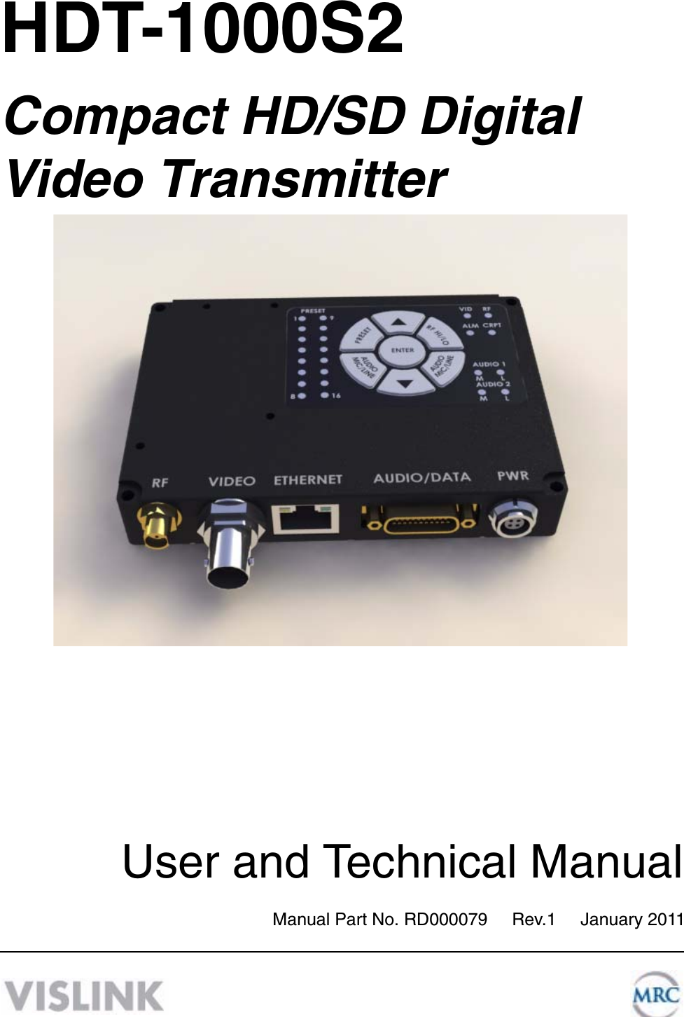
Microwave Radio Communications LLC Compact HD/SD Digital Video Transmitter HDT 1000 S2 User Manual Rev 1
UserManual.wiki
>
Microwave Radio Communications
>
HDT1000LS User Manual
Manual
Navigation menu
Upload a User Manual
Namespaces
Wiki Guide
HTML
PDF
Info
Views
User Manual
Discussion / Help
Navigation
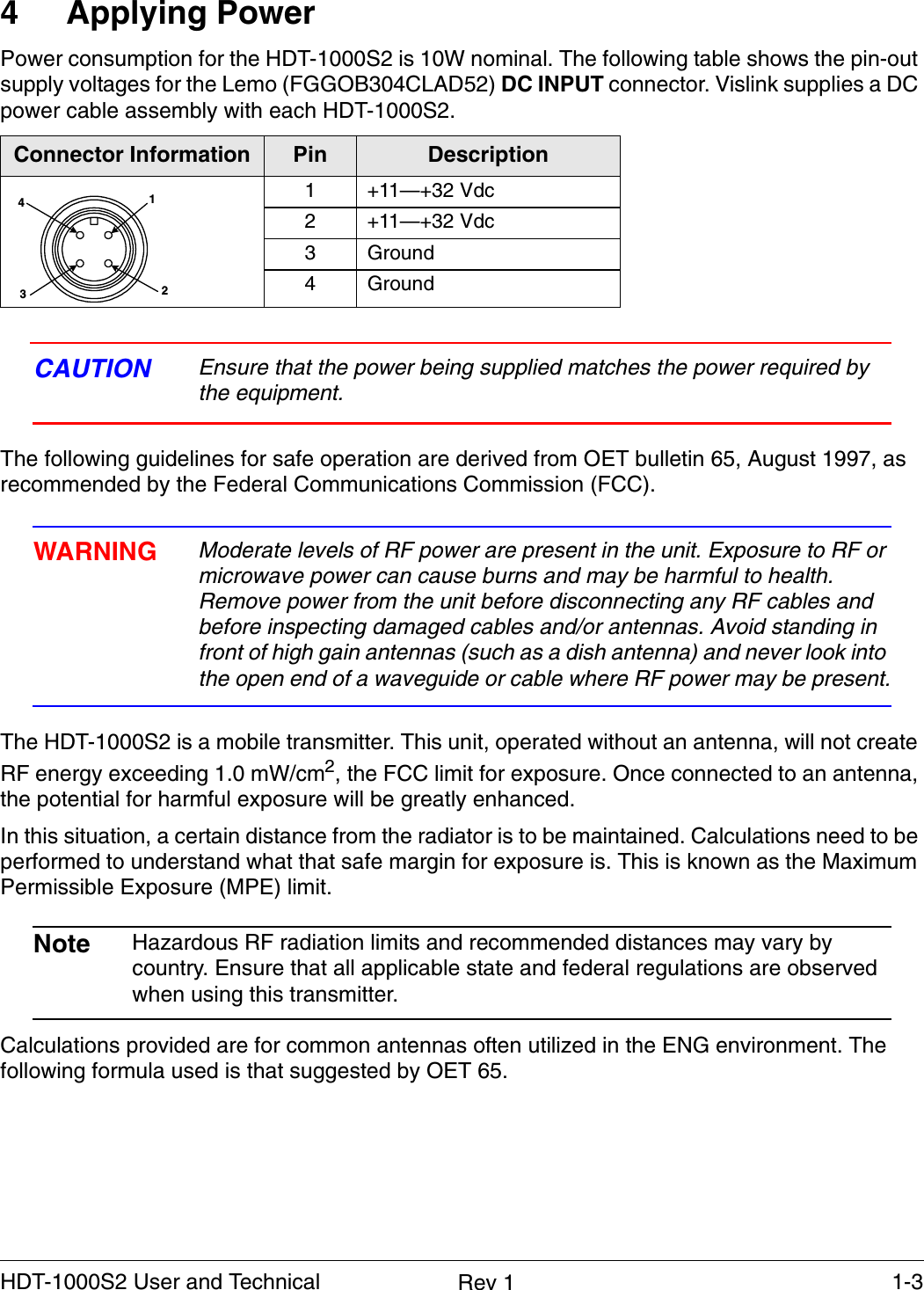
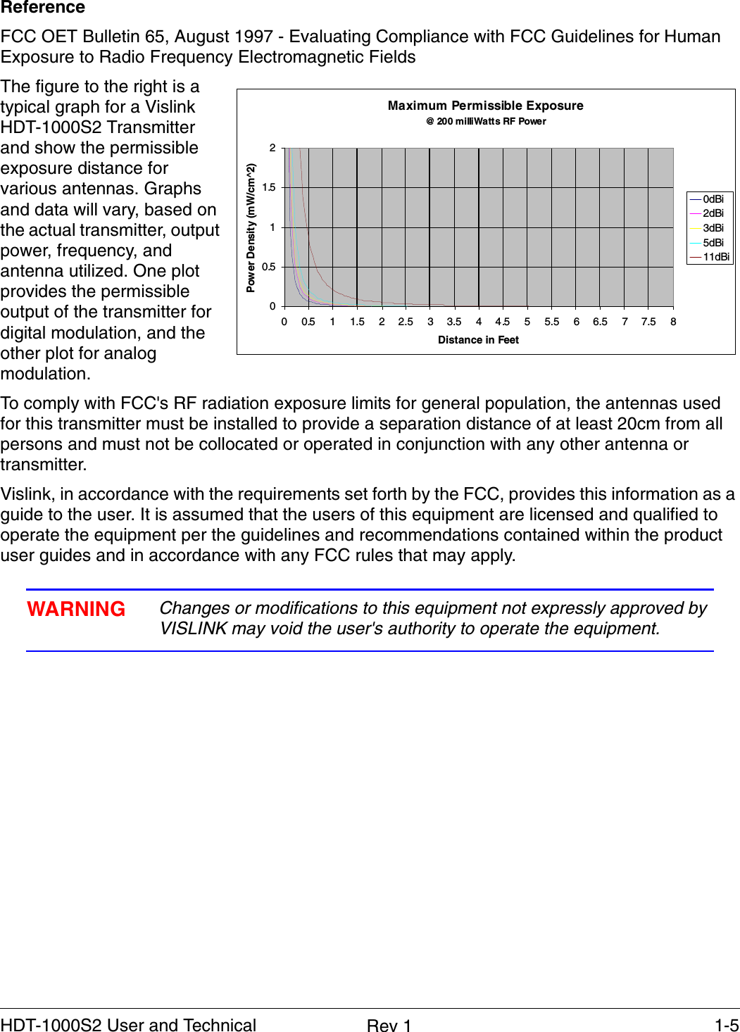
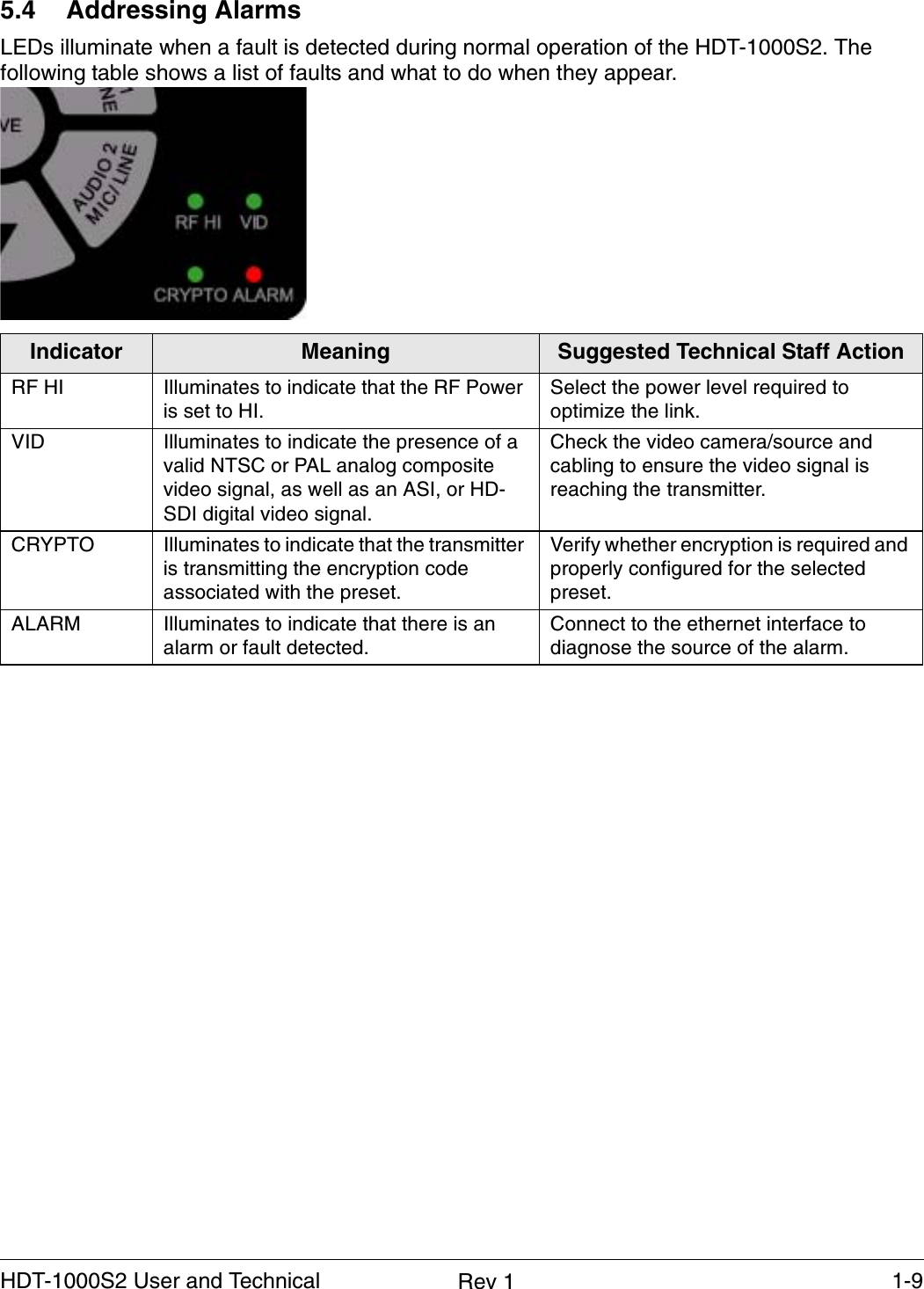
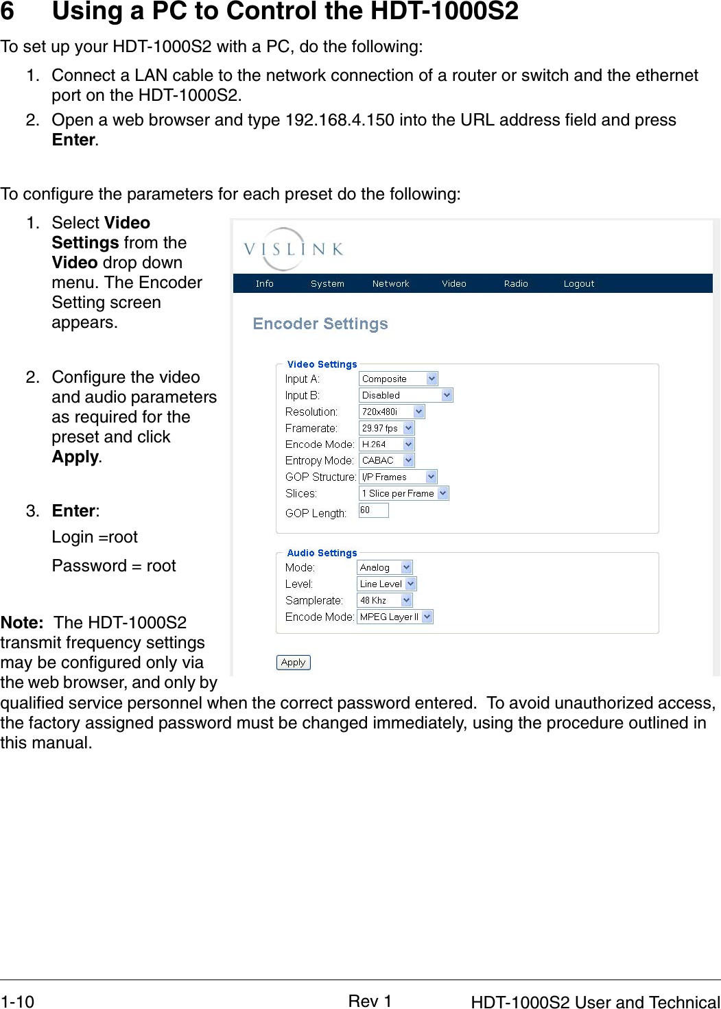
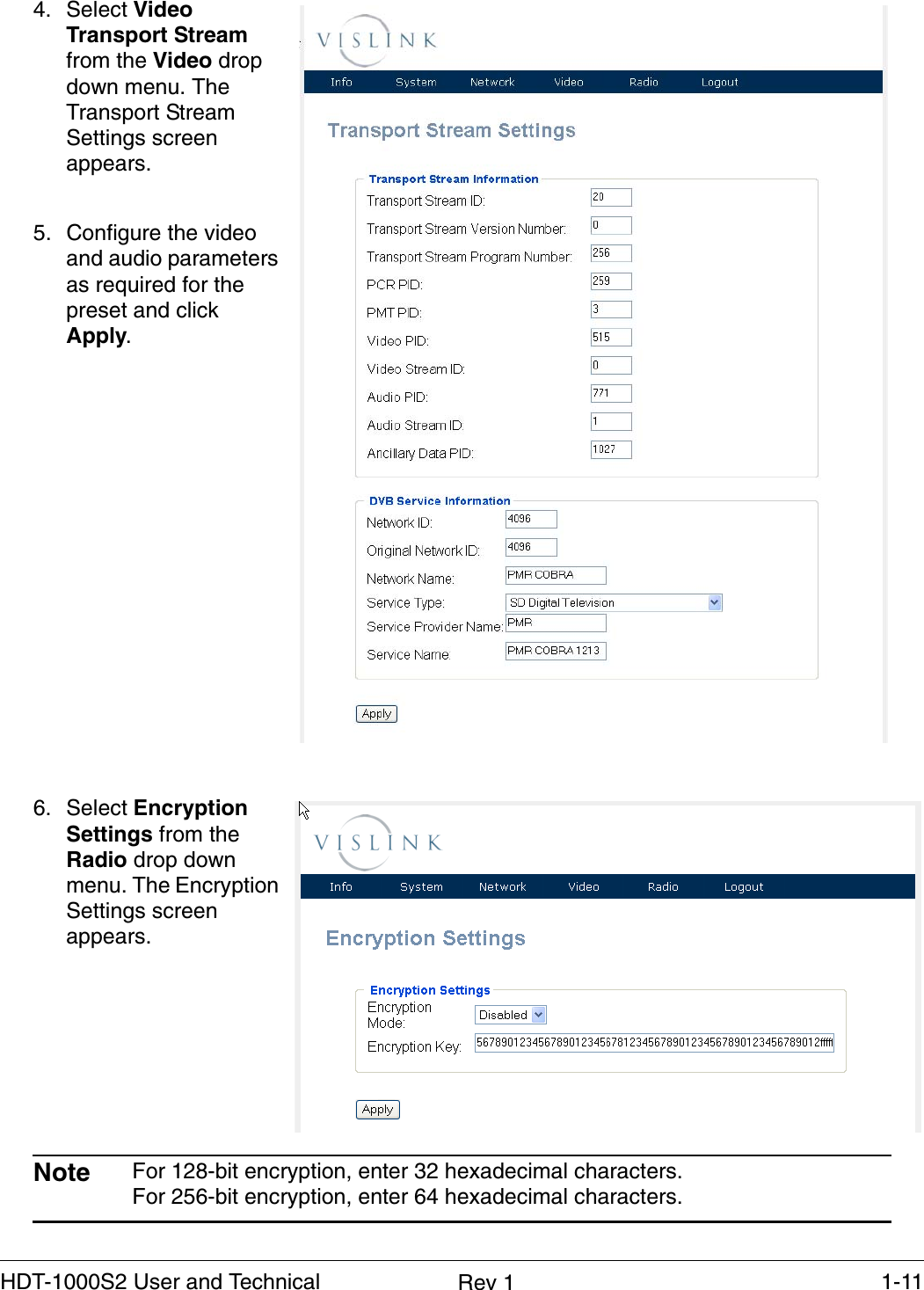
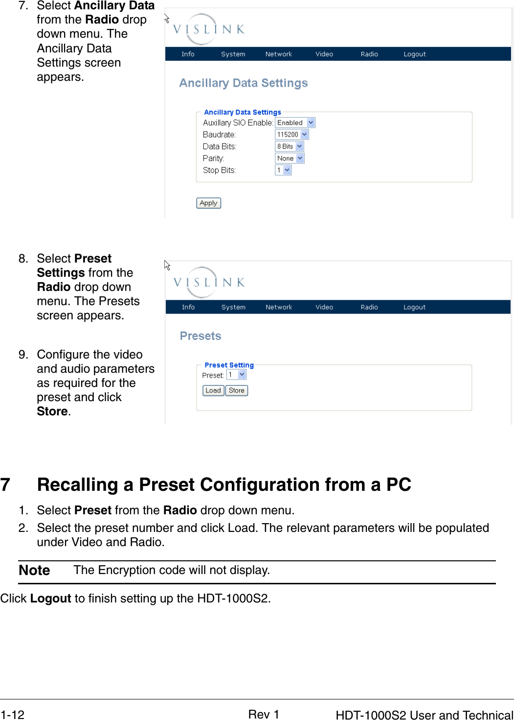
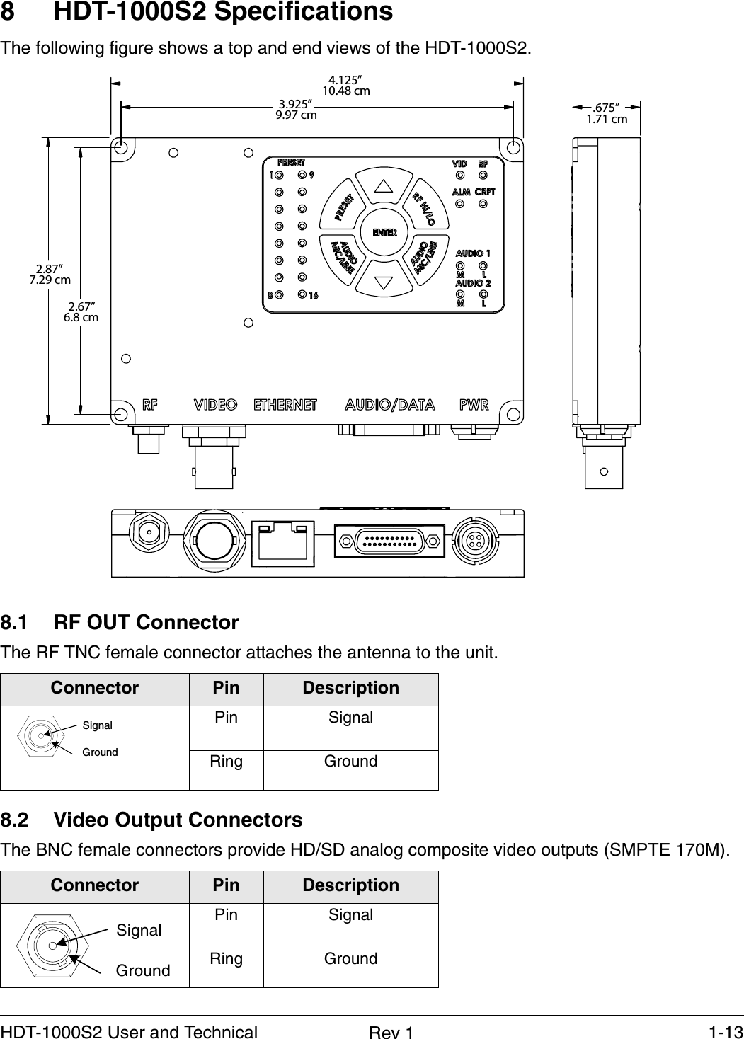
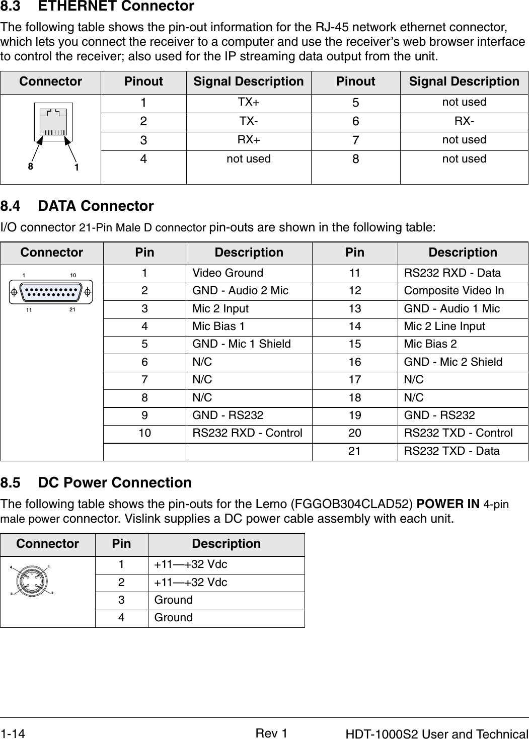
![1-4 HDT-1000S2 User and TechnicalRev 1Calculating MPEEIRP = P * (10 ^ (G / 10)) = (antilog of G/10) * PP = RF power delivered to the antenna in mWG = Power gain of the antenna in the direction of interest relative to an isotropic radiatorR = distance to the center of radiation of the antenna in centimetersS = MPE in mW/cm² (milliwatts per square centimeters)ConversionsdBi to numeric gain = Antilog (dBi/10)Feet to centimeters = Feet * 30.48Centimeters to Feet = cm * .03284 π = 12.57User InputRF power delivered to the antenna = WattsAntenna gain (referenced to isotropic antenna) = dBiDistance from the center of radiation = FeetCalculation steps:1. [P] RF power input. Watts to milliwatts = Watts * 10002. [G] Antenna gain dBi. Numeric gain = Antilog (dBi/10)3. [EIRP] Multiply P * G 4. [R] Centimeters to feet = Centimeters * .03285. Square R6. Multiply R² * 4π7. [S] Divide (R² * 4π) into EIRPS = Power Density in milliwatts per square centimeters. Note At frequencies above 1500 MHz, S must not be greater than 1.](https://usermanual.wiki/Microwave-Radio-Communications/HDT1000LS/User-Guide-1423545-Page-6.png)