Microwave Radio Communications HDT1000LS Compact HD/SD Digital Video Transmitter User Manual HDT 1000 S2 User Manual Rev 1
Microwave Radio Communications LLC Compact HD/SD Digital Video Transmitter HDT 1000 S2 User Manual Rev 1
Manual
User and Technical Manual
Preliminary Draft - April 2010
HDT-1000S2
Compact HD/SD Digital
Video Transmitter
Manual Part No. RD000079 Rev.1 January 2011
Preliminary Draft - April 2010
Copyright © 2011
Part number RD000079
Printed in U.S.A.
Authorized EU representative: Vislink PLC
Quality Certification Vislink is certified to ISO 9001:2008.
The Vislink trademark and other trademarks are registered trademarks in the United States and/or other countries.
Microsoft®, Windows®, and Internet Explorer® are registered trademarks of Microsoft Corporation in the United States
and/or other countries.
Proprietary Material The information and design contained within this manual was originated by and is the property
of Vislink. Vislink reserves all patent proprietary design, manufacturing, reproduction use, and sales rights thereto, and
to any articles disclosed therein, except to the extent rights are expressly granted to others. The foregoing does not
apply to vendor proprietary parts. Vislink has made every effort to ensure the accuracy of the material contained in this
manual at the time of printing. As specifications, equipment, and this manual are subject to change without notice,
Vislink assumes no responsibility or liability whatsoever for any errors or inaccuracies that may appear in this manual
or for any decisions based on its use. This manual is supplied for information purposes only and should not be
construed as a commitment by Vislink. The information in this manual remains the property of Vislink and may not be
used, disclosed, or reproduced in any form whatsoever, without the prior written consent of Vislink. Vislink reserves the
right to make changes to equipment and specifications of the product described in this manual at any time without
notice and without obligation to notify any person of such changes.
General Safety Information The following safety requirements, as well as local site requirements and regulations,
must be observed by personnel operating and maintaining the equipment covered by this manual to ensure awareness
of potential hazards. This equipment has been tested and found to comply with the limits for a Class A digital device,
pursuant to Part 15 of the FCC Rules. These limits are designed to provide reasonable protection against harmful
interference when the equipment is operated in a commercial environment. This equipment generates, uses, and can
radiate radio frequency energy. If not installed and used in accordance with the instruction manual, it may cause
harmful interference to radio communications. Operation of this equipment in a residential area is likely to cause
harmful interference in which case the user will be required to correct the interference at his own expense.
About this Manual This manual is intended for use by qualified operators, installers, and service personnel. Users of
this manual should already be familiar with basic concepts of radio, video, and audio. For information about terms in
this manual, see Glossary of Terms and Abbreviations (Part No. 400576-1). Pay special attention to Notes, Cautions,
and Warnings.
Read Notes for important information to assist you in using and maintaining the equipment.
Follow CAUTIONS to prevent damage to the equipment.
Follow WARNINGS to prevent personal injury or death.
Symbols The following symbols may be on the equipment or in this manual:
WARNING: General Warning.
Risk of Danger.
Frame or Chassis Ground: Identifies the frame
or chassis terminal.
WARNING: Risk of Electric Shock. Earth Ground: Identifies the earth ground
terminal.
CAUTION: Electrostatic Discharge.
Possible Damage to Equipment.
Fuse: Identifies fuses or their location.
Protective Earth Ground: Identifies any
terminal intended for connection to an
external conductor for protection against elec-
tric shock in case of a fault, or the
terminal on a protective earth electrode.
Waste Electrical and Electronic Equipment
(WEEE): The product must not be disposed of
with other waste. You must dispose of the
waste equipment by handing it over to a desig-
nated collection point for recycling.
101 Billerica Avenue - Bldg. 6
North Billerica, MA 01862-1256 USA
TEL: 800.490.5700 or +1.978.671.5700
1-1HDT-1000S2 User and Technical Rev 1
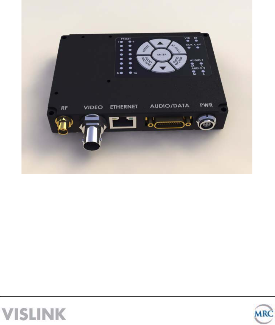
1 About the HDT-1000S2
The HDT-1000S2 Compact HD/SD Digital Video Transmitter is designed for short-range,
portable and fixed transmission applications and transmits remote video to a central receive
location. The HDT-1000S2 is designed to transmit up to two NTSC (or PAL) standard definition
(SD) video signals or one high-definition (HD) video signal (up to 1080i) plus two audio signals
and an RS-232 data channel. Common uses include law enforcement surveillance and video
collection.
The HDR-1000 can transmit DVB-T COFDM digital transmissions consisting of either standard
definition (SD) (NTSC or PAL) or high-definition (HD) video formats. The transmitter uses the
H.264 MPEG video compression format for high-quality imagery.
Accessories You can order an RF cable, omni antenna, and encryption license.
2 Band and Frequency of Operation
The HDT-1000S2 covers the following range:
• HDT-1000S2 S2 band 2.41—2.45 GHz (unlicensed)*
* Unlicensed operation under FCC Part 15 in S Band is factory limited to 2.414 - 2.458 GHz
This device complies with part 15 of the FCC Rules. Operation is subject to the following two
conditions: (1) This device may not cause harmful interference, and (2) this device must accept
any interference received, including interference that may cause undesired operation

1-2 HDT-1000S2 User and Technical
Rev 1
3 Unpacking the HDT-1000S2
Before you install your new equipment, carefully unpack your new equipment to avoid
accidental damage.
• Locate all parts and accessories and verify that they are listed on the packing list. DO
NOT discard the container or packing material until you have inspected the equipment
and are sure there is no shipping damage. The container and packing must be available
in case you need to file a damage claim with the shipping carrier.
• Inspect the equipment for damage and that it is clean and dry.
• Inspect the cables, connectors, switches, and displays to ensure that they are not
broken, damaged, or loose.
If you discover damage after unpacking the system, report the damage as follows:
• Immediately file a claim with the shipping carrier.
• Forward a copy of the damage report to Vislink Customer Service.
Contact Vislink Customer Service to determine the disposition of the equipment.
You can connect the following cables to the HDT-1000S2.
Audio Input Audio is input to the HDT-1000S2 through the 21-pin front panel connector.
Branched cable assemblies are available for either microphone or line level
input to the HDT-1000 transmitter.
RS-232 Control You can control the HDT-1000S2 using an RS-232 command set. A branched
cable assembly is available to connect the 21-pin front panel connector to a
DB-9M connector.
Auxiliary Data You can transmit the auxiliary RS-232 data through the HDT-1000. A branched
cable assembly is available to connect the 21-pin front panel connector to a
DB-9M connector.
Video Input Video is input to the HDT-1000S2 through the front panel BNC connector. The
HDT-1000S2 accepts an NTSC or PAL analog composite signal, as well as an
ASI, or HD-SDI digital video signal. You select between analog or digital video
input using the web server software.

1-3HDT-1000S2 User and Technical Rev 1
4 Applying Power
Power consumption for the HDT-1000S2 is 10W nominal. The following table shows the pin-out
supply voltages for the Lemo (FGGOB304CLAD52) DC INPUT connector. Vislink supplies a DC
power cable assembly with each HDT-1000S2.
CAUTION Ensure that the power being supplied matches the power required by
the equipment.
The following guidelines for safe operation are derived from OET bulletin 65, August 1997, as
recommended by the Federal Communications Commission (FCC).
WARNING Moderate levels of RF power are present in the unit. Exposure to RF or
microwave power can cause burns and may be harmful to health.
Remove power from the unit before disconnecting any RF cables and
before inspecting damaged cables and/or antennas. Avoid standing in
front of high gain antennas (such as a dish antenna) and never look into
the open end of a waveguide or cable where RF power may be present.
The HDT-1000S2 is a mobile transmitter. This unit, operated without an antenna, will not create
RF energy exceeding 1.0 mW/cm2, the FCC limit for exposure. Once connected to an antenna,
the potential for harmful exposure will be greatly enhanced.
In this situation, a certain distance from the radiator is to be maintained. Calculations need to be
performed to understand what that safe margin for exposure is. This is known as the Maximum
Permissible Exposure (MPE) limit.
Note Hazardous RF radiation limits and recommended distances may vary by
country. Ensure that all applicable state and federal regulations are observed
when using this transmitter.
Calculations provided are for common antennas often utilized in the ENG environment. The
following formula used is that suggested by OET 65.
Connector Information Pin Description
1 +11—+32 Vdc
2 +11—+32 Vdc
3 Ground
4 Ground
1
2
3
4

1-4 HDT-1000S2 User and Technical
Rev 1
Calculating MPE
EIRP = P * (10 ^ (G / 10)) = (antilog of G/10) * P
P = RF power delivered to the antenna in mW
G = Power gain of the antenna in the direction of interest relative to an isotropic radiator
R = distance to the center of radiation of the antenna in centimeters
S = MPE in mW/cm² (milliwatts per square centimeters)
Conversions
dBi to numeric gain = Antilog (dBi/10)
Feet to centimeters = Feet * 30.48
Centimeters to Feet = cm * .0328
4 π = 12.57
User Input
RF power delivered to the antenna = Watts
Antenna gain (referenced to isotropic antenna) = dBi
Distance from the center of radiation = Feet
Calculation steps:
1. [P] RF power input. Watts to milliwatts = Watts * 1000
2. [G] Antenna gain dBi. Numeric gain = Antilog (dBi/10)
3. [EIRP] Multiply P * G
4. [R] Centimeters to feet = Centimeters * .0328
5. Square R
6. Multiply R² * 4π
7. [S] Divide (R² * 4π) into EIRP
S = Power Density in milliwatts per square centimeters.
Note At frequencies above 1500 MHz, S must not be greater than 1.

1-5HDT-1000S2 User and Technical Rev 1
Reference
FCC OET Bulletin 65, August 1997 - Evaluating Compliance with FCC Guidelines for Human
Exposure to Radio Frequency Electromagnetic Fields
The figure to the right is a
typical graph for a Vislink
HDT-1000S2 Transmitter
and show the permissible
exposure distance for
various antennas. Graphs
and data will vary, based on
the actual transmitter, output
power, frequency, and
antenna utilized. One plot
provides the permissible
output of the transmitter for
digital modulation, and the
other plot for analog
modulation.
To comply with FCC's RF radiation exposure limits for general population, the antennas used
for this transmitter must be installed to provide a separation distance of at least 20cm from all
persons and must not be collocated or operated in conjunction with any other antenna or
transmitter.
Vislink, in accordance with the requirements set forth by the FCC, provides this information as a
guide to the user. It is assumed that the users of this equipment are licensed and qualified to
operate the equipment per the guidelines and recommendations contained within the product
user guides and in accordance with any FCC rules that may apply.
WARNING Changes or modifications to this equipment not expressly approved by
VISLINK may void the user's authority to operate the equipment.
Maximum Permissible Exposure
@ 200 milliWatts RF Power
0
0.5
1
1.5
2
00.511.522.533.544.555.566.5 77.58
Distance in Feet
Power Density (mW/cm^2)
0dBi
2dBi
3dBi
5dBi
11dBi
1-6 HDT-1000S2 User and Technical
Rev 1
5 Setting Up the HDT-1000S2
You can select presets from the membrane switch control. You can modify preset parameters
using a PC with either the Microsoft® Windows XP® or Microsoft® Windows Vista® operating
systems. You can configure up to 16 individual preset configurations as follows:
• Select from 16 factory or custom preset configurations
• Configure and save up to 16 custom preset configurations
• Load custom preset configurations from a file on your PC into your HDT-1000S2.
• Apply an encryption key to the presets simultaneously or individually.
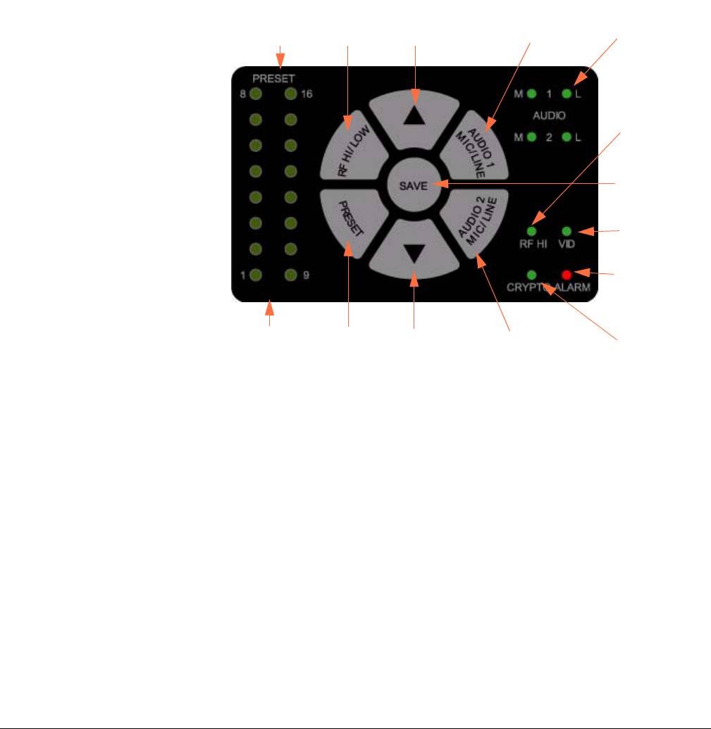
The figure to the right and
associated table shows the
membrane switch control
where you select a preset,
low or high radio frequency,
and audio selections.
The switch control contains a
“dark” timer that turns off
LEDs after a delay. All LEDs
are active for 0.5 seconds
after the unit is powered up.
Up Arrow
Key
AUDIO
LEDs
PRESET
LEDs
VID
LED
ALARM
LED
RF HI
LED
Down
Arrow Key
Multi-LED
display
SAVE Key
PRESET
Key
RF HI/LOW
Key
AUDIO 1
MIC/LINE
Key
CRYTPO
LED
AUDIO 2
MIC/LINE
Key

1-7HDT-1000S2 User and Technical Rev 1
Membrane Switch Control Features
5.1 Selecting a Preset
The HDT-1000S2 recalls the most recently saved preset when it is powered up. To select a
preset, do the following:
1. Press the PRESET key. The currently selected preset LED flashes.
2. Press the up and down arrows to choose the new preset you want.
3. Press the SAVE key. The preset LED flashes to indicate the preset was chosen and the
LED is illuminated to indicate the operational preset.
If the SAVE key is not pressed within 5 seconds, the preset returns to the most recently used
value and the selection mode is canceled.
PRESET LED Displays the selected preset (1-16).
RF HI/LOW Toggle between high and low power output.
Up arrow Move up through presets.
AUDIO 1
MIC/LINE
Press to set Audio 1to Mic or Line and press SAVE to set.
Audio LEDs Green when enabled; otherwise dark. M=MIC; L=LINE
RF HI LED Green when the radio power output is high; dark when low.
SAVE Sets new preset.
VID LED Green when a valid NTSC or PAL analog composite video signal, as well as an
ASI, or HD-SDI digital video signal is present; otherwise dark
ALARM LED Red when an alarm occurs; otherwise dark.
CRYPTO LED Green when encryption is enabled and the transmitter is transmitting the
encryption code associated with the preset; dark when disabled.
AUDIO 2
MIC/LINE
Press to set Audio 2 to Mic or Line and press SAVE to set.
Down arrow Move down through presets.
PRESET key Press to select one of the stored presets (1-16). The PRESET LED indicates
the current preset. Use the up or down arrow to select a new preset. Press
SAVE to select the new setting.
Multi-LED display Indicates which preset is being used. The LEDs remain lit until another option
button is selected or until the dark timer elapses.

1-8 HDT-1000S2 User and Technical
Rev 1
5.2 Selecting the Audio Input Level
The HDT-1000S2 recalls the most recently saved audio input level setting when it is powered
up. To select the input level for Audio 1 and Audio 2 between microphone or line level, do the
following:
1. Press the AUDIO 1 MIC/LINE or AUDIO 2 MIC/LINE key. The currently selected audio
level LED flashes.
2. Press AUDIO 1 MIC/LINE or AUDIO 2 MIC/LINE key to toggle between MIC or LINE
level.
3. Press the SAVE key. The audio level LED flashes to indicate the audio input level was
selected and the LED is illuminated to indicate MIC or LINE level setting.
If the SAVE key is not pressed within 5 seconds, the audio level returns to the most recently
used value and the selection mode is canceled.
5.3 Selecting the RF Output Level
The HDT-1000S2 recalls the most recently saved RF output power level when it is powered up.
To select between high or low power for the RF output level, do the following:
1. Press the RF HI/LOW key. The currently selected RF Power setting is displayed.
2. Press RF HI/LOW key to toggle between HI or LOW RF output level.
3. Press the SAVE key to select the new RF Power output setting.
If the SAVE key is not pressed within 5 seconds, the RF output level returns to the most recently
used value and the selection mode is canceled.
Note The high power setting is the FCC limit of 0.125W maximum, the low power
setting is approximately 0.05W.
1-9HDT-1000S2 User and Technical Rev 1
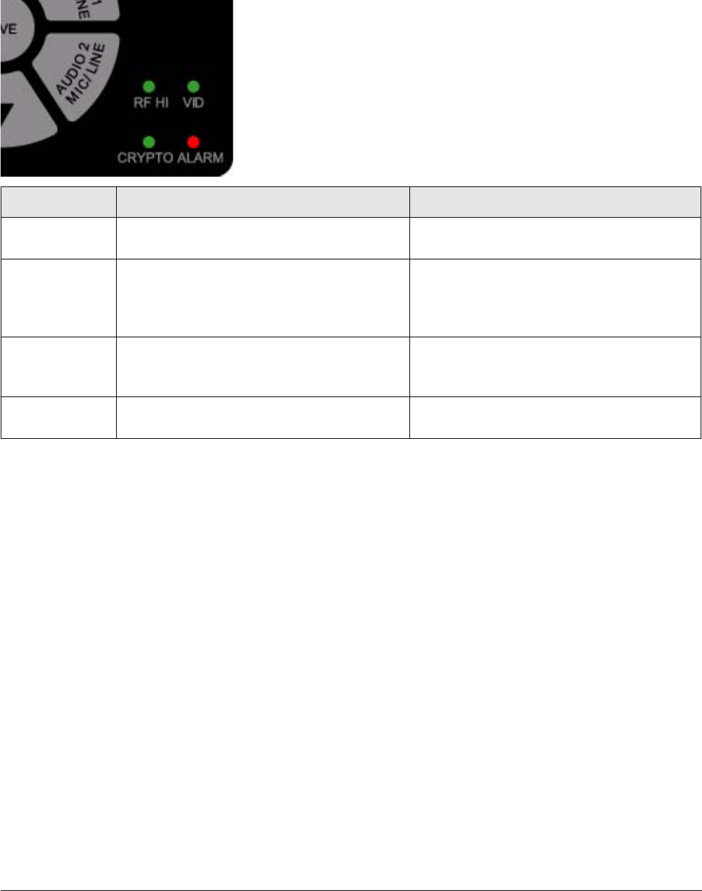
5.4 Addressing Alarms
LEDs illuminate when a fault is detected during normal operation of the HDT-1000S2. The
following table shows a list of faults and what to do when they appear.
Indicator Meaning Suggested Technical Staff Action
RF HI Illuminates to indicate that the RF Power
is set to HI.
Select the power level required to
optimize the link.
VID Illuminates to indicate the presence of a
valid NTSC or PAL analog composite
video signal, as well as an ASI, or HD-
SDI digital video signal.
Check the video camera/source and
cabling to ensure the video signal is
reaching the transmitter.
CRYPTO Illuminates to indicate that the transmitter
is transmitting the encryption code
associated with the preset.
Verify whether encryption is required and
properly configured for the selected
preset.
ALARM Illuminates to indicate that there is an
alarm or fault detected.
Connect to the ethernet interface to
diagnose the source of the alarm.
1-10 HDT-1000S2 User and Technical
Rev 1
6 Using a PC to Control the HDT-1000S2
To set up your HDT-1000S2 with a PC, do the following:
1. Connect a LAN cable to the network connection of a router or switch and the ethernet
port on the HDT-1000S2.
2. Open a web browser and type 192.168.4.150 into the URL address field and press
Enter.
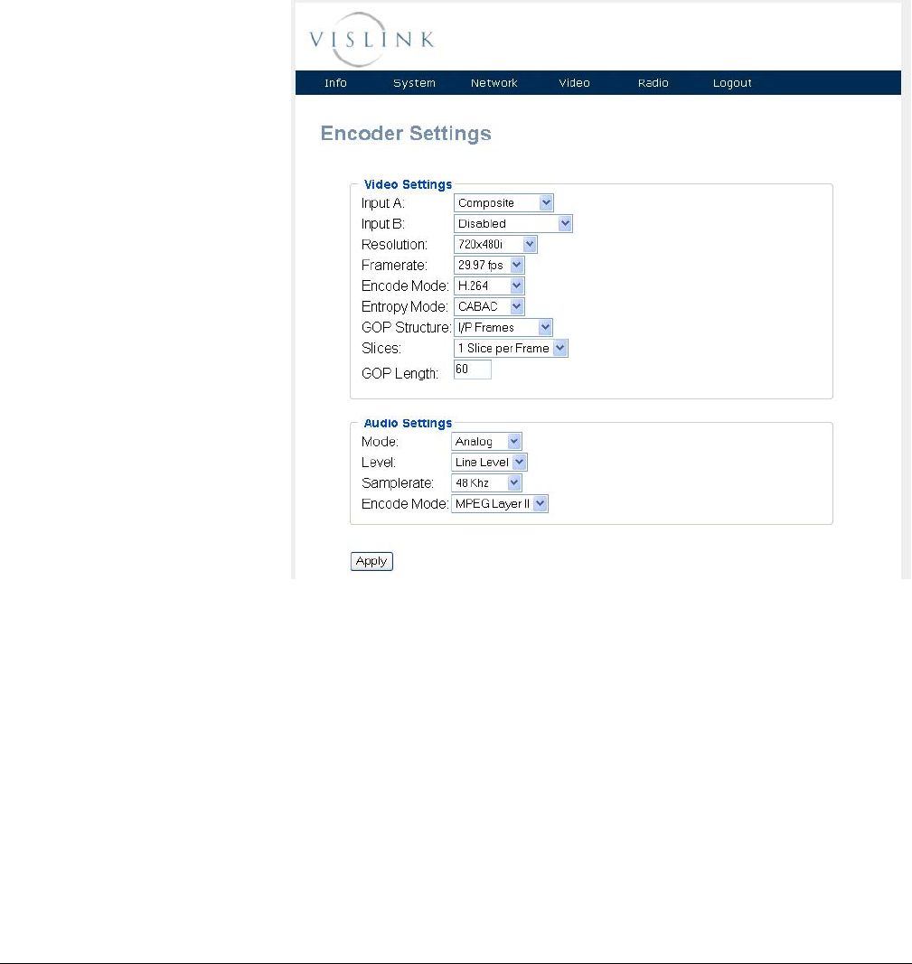
To configure the parameters for each preset do the following:
1. Select Video
Settings from the
Video drop down
menu. The Encoder
Setting screen
appears.
2. Configure the video
and audio parameters
as required for the
preset and click
Apply.
3. Enter:
Login =root
Password = root
Note: The HDT-1000S2
transmit frequency settings
may be configured only via
the web browser, and only by
qualified service personnel when the correct password entered. To avoid unauthorized access,
the factory assigned password must be changed immediately, using the procedure outlined in
this manual.
1-11HDT-1000S2 User and Technical Rev 1
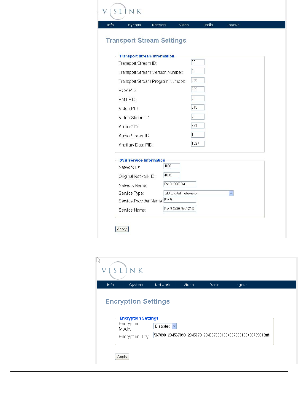
4. Select Video
Transport Stream
from the Video drop
down menu. The
Transport Stream
Settings screen
appears.
5. Configure the video
and audio parameters
as required for the
preset and click
Apply.
6. Select Encryption
Settings from the
Radio drop down
menu. The Encryption
Settings screen
appears.
Note For 128-bit encryption, enter 32 hexadecimal characters.
For 256-bit encryption, enter 64 hexadecimal characters.

1-12 HDT-1000S2 User and Technical
Rev 1
7. Select Ancillary Data
from the Radio drop
down menu. The
Ancillary Data
Settings screen
appears.
8. Select Preset
Settings from the
Radio drop down
menu. The Presets
screen appears.
9. Configure the video
and audio parameters
as required for the
preset and click
Store.
7 Recalling a Preset Configuration from a PC
1. Select Preset from the Radio drop down menu.
2. Select the preset number and click Load. The relevant parameters will be populated
under Video and Radio.
Note The Encryption code will not display.
Click Logout to finish setting up the HDT-1000S2.
1-13HDT-1000S2 User and Technical Rev 1
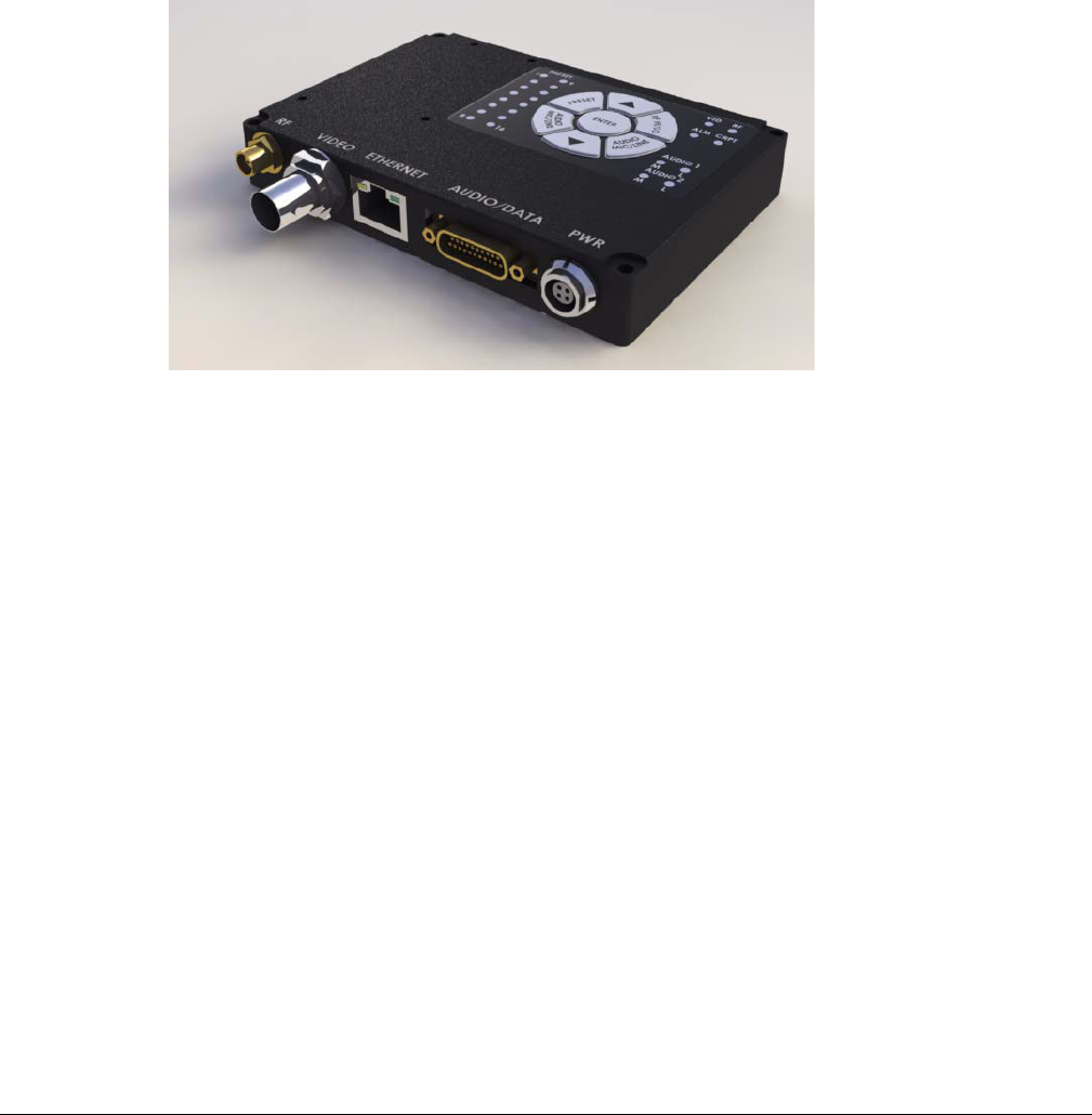
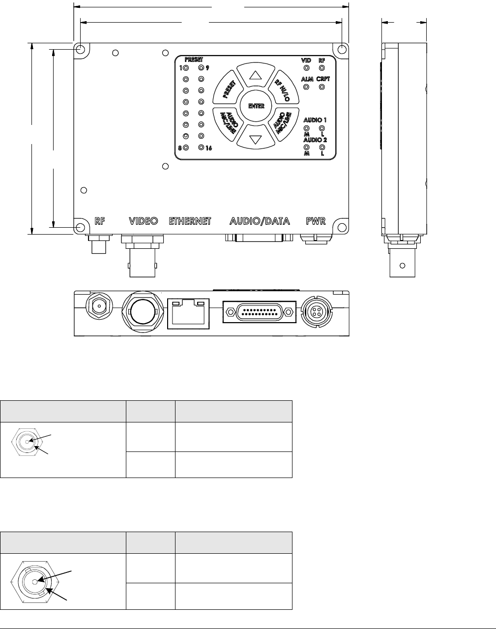
8 HDT-1000S2 Specifications
The following figure shows a top and end views of the HDT-1000S2.
8.1 RF OUT Connector
The RF TNC female connector attaches the antenna to the unit.
8.2 Video Output Connectors
The BNC female connectors provide HD/SD analog composite video outputs (SMPTE 170M).
Connector Pin Description
Pin Signal
Ring Ground
Connector Pin Description
Pin Signal
Ring Ground
4.125”
10.48 cm
3.925”
9.97 cm .675”
1.71 cm
2.87”
7.29 cm
2.67”
6.8 cm
Signal
Ground
Signal
Ground
1-14 HDT-1000S2 User and Technical
Rev 1
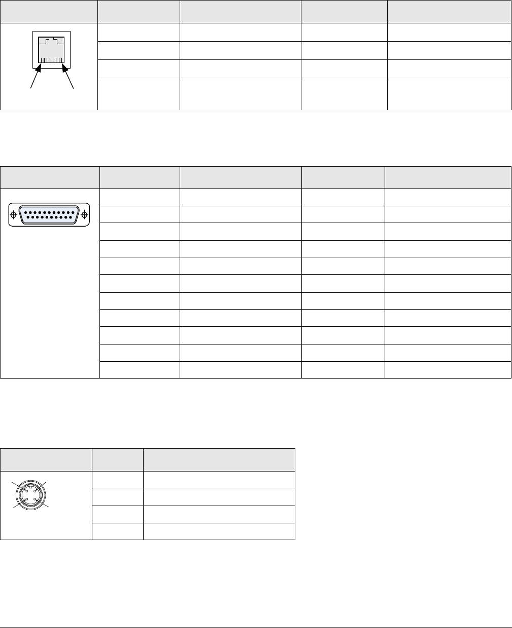
8.3 ETHERNET Connector
The following table shows the pin-out information for the RJ-45 network ethernet connector,
which lets you connect the receiver to a computer and use the receiver’s web browser interface
to control the receiver; also used for the IP streaming data output from the unit.
8.4 DATA Connector
I/O connector 21-Pin Male D connector pin-outs are shown in the following table:
8.5 DC Power Connection
The following table shows the pin-outs for the Lemo (FGGOB304CLAD52) POWER IN 4-pin
male power connector. Vislink supplies a DC power cable assembly with each unit.
Connector Pinout Signal Description Pinout Signal Description
1TX+ 5not used
2TX- 6RX-
3RX+ 7not used
4not used 8not used
Connector Pin Description Pin Description
1 Video Ground 11 RS232 RXD - Data
2 GND - Audio 2 Mic 12 Composite Video In
3 Mic 2 Input 13 GND - Audio 1 Mic
4 Mic Bias 1 14 Mic 2 Line Input
5 GND - Mic 1 Shield 15 Mic Bias 2
6 N/C 16 GND - Mic 2 Shield
7N/C 17N/C
8N/C 18N/C
9 GND - RS232 19 GND - RS232
10 RS232 RXD - Control 20 RS232 TXD - Control
21 RS232 TXD - Data
Connector Pin Description
1 +11—+32 Vdc
2 +11—+32 Vdc
3 Ground
4 Ground
1
8
110
11 21
1
2
3
4

1-15HDT-1000S2 User and Technical Rev 1
9 Getting Support for Your HDT-1000S2
You can contact the Vislink Technical Support staff as follows:
24-hour Worldwide Technical Support
E-mail: support@mrcbroadcast.com
Telephone: +1 978-671-5929 or
888-777-9221
Customer Service
E-mail: customerservice@mrcbroadcast.com
Telephone: +1 978-671-5700 Press 3
Monday-Friday, 8AM-5PM EST USA
When you contact Technical Support, include the following information:
• Model number and serial number of the unit (located on a label on the bottom of each
unit).
• Approximate purchase date.
There are no supported field repairs or replacement parts for the HDT-1000S2 system.
Return the unit for factory repair.
CAUTION If you attempt field repair, you risk damaging your equipment. If
your equipment is under warranty, you may also affect your warranty
coverage. The HDT-1000S2 requires specialized test equipment and
software to calibrate operating characteristics after repair.
Replacement Parts The only part available is the 21-pin Multi-use (audio, control, data)
breakout cable that provides connections to the HDT-1000S2.

1-16 HDT-1000S2 User and Technical
Rev 1