Microwave Radio Communications ODU2ATXADH 2GHz MTX Radio User Manual MTX User and Tech
Microwave Radio Communications LLC 2GHz MTX Radio MTX User and Tech
UserManual.wiki
>
Microwave Radio Communications
>
ODU2ATXADH User Manual
>
Manual Part 2
Contents
1.
Manual Part 1
2.
Manual Part 2
Manual Part 2
Navigation menu
Upload a User Manual
Namespaces
Wiki Guide
HTML
PDF
Info
Views
User Manual
Discussion / Help
Navigation
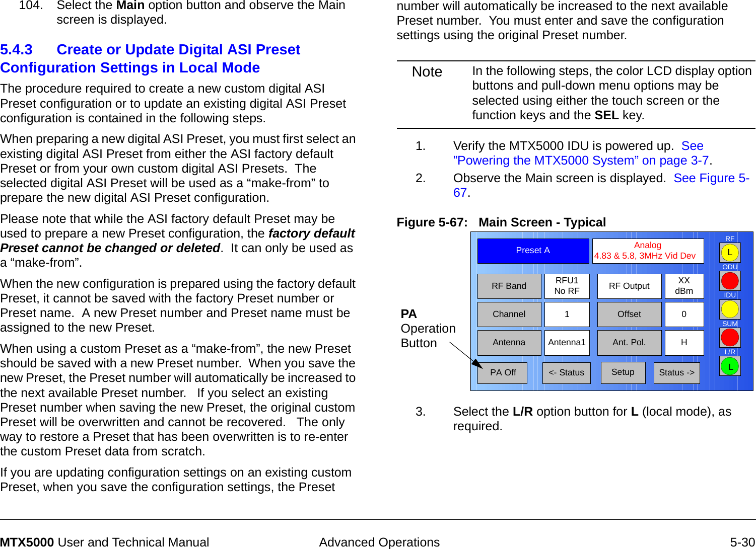
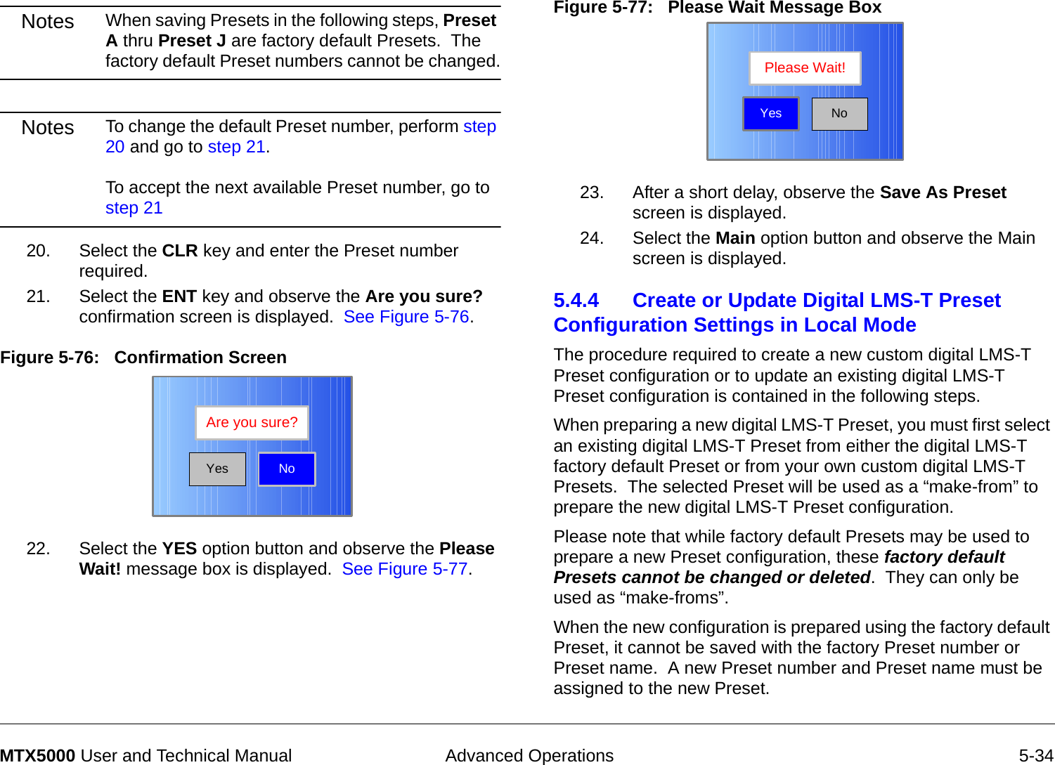
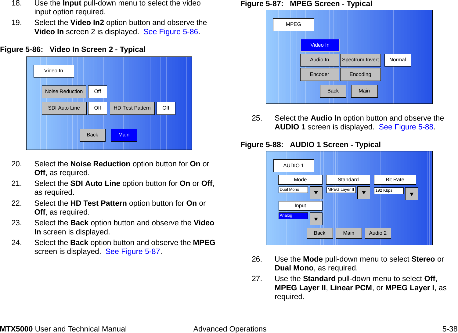
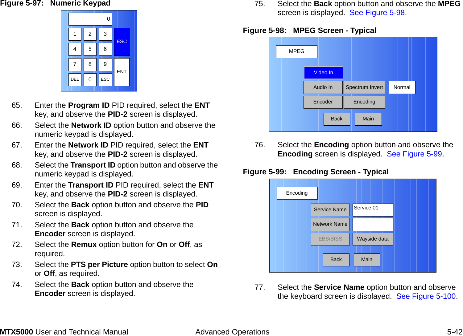
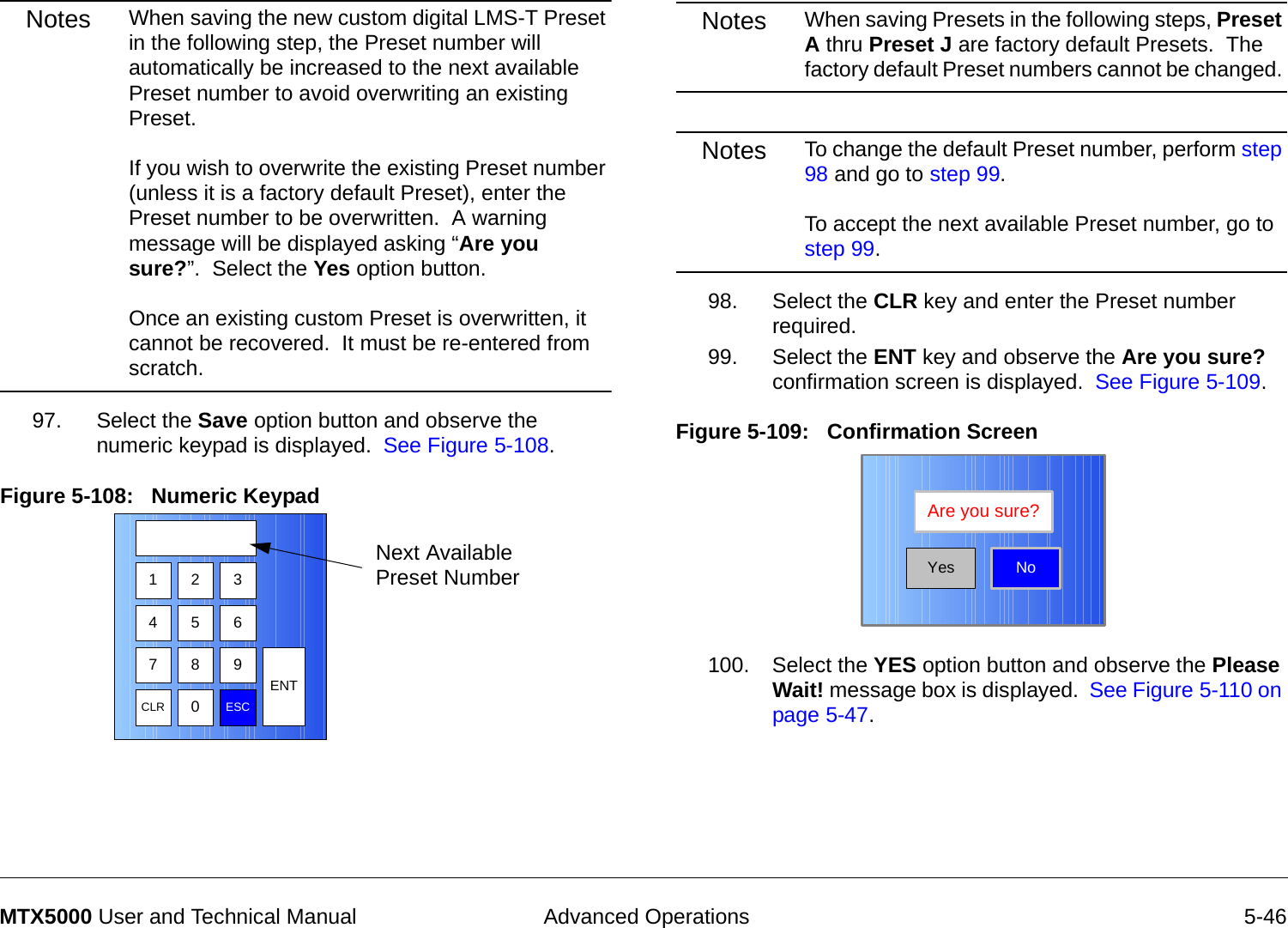
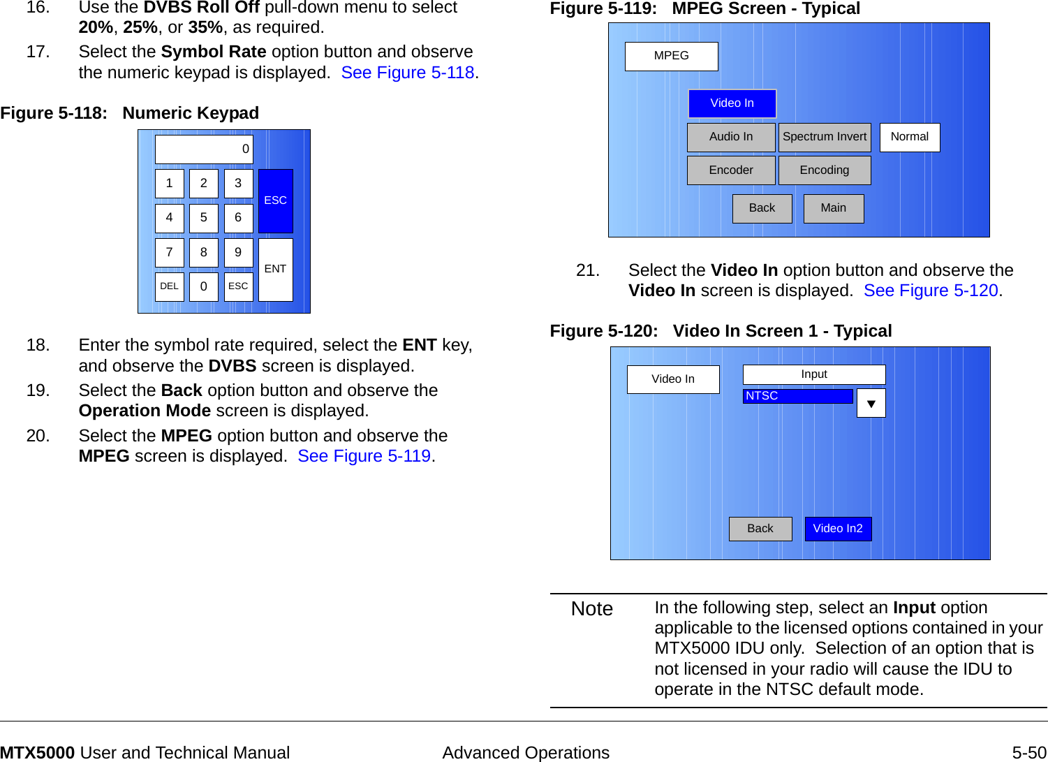
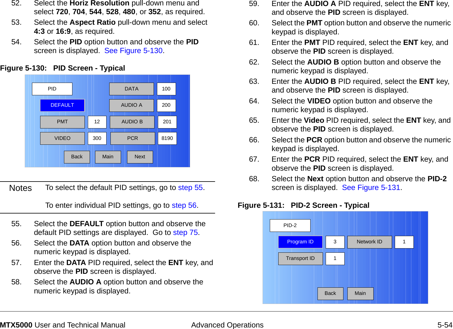
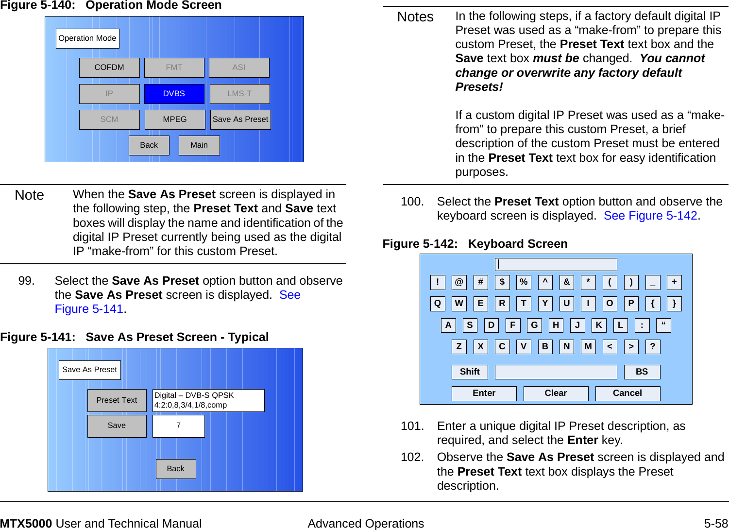
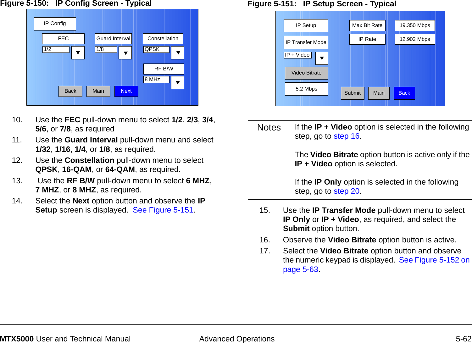
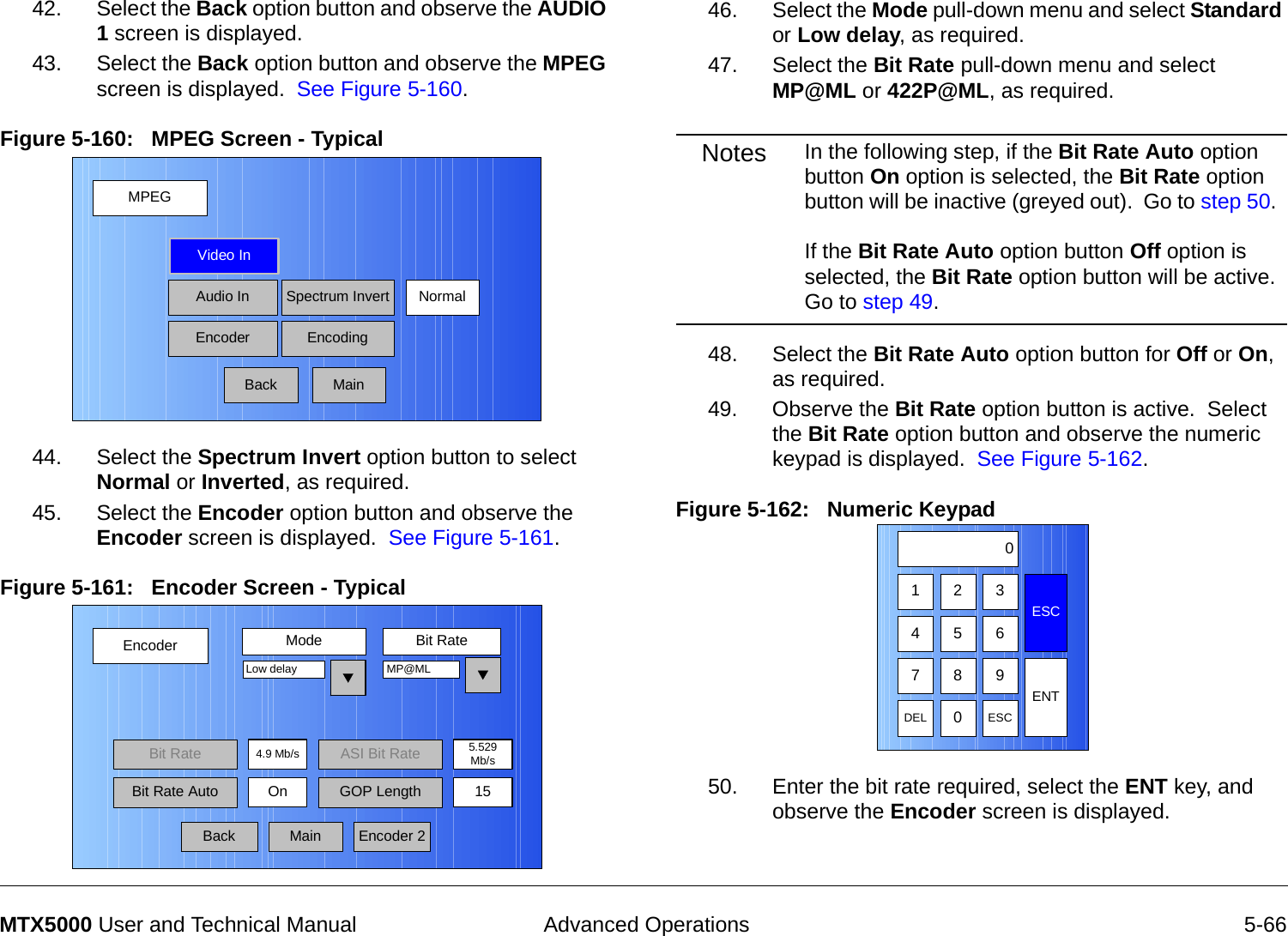
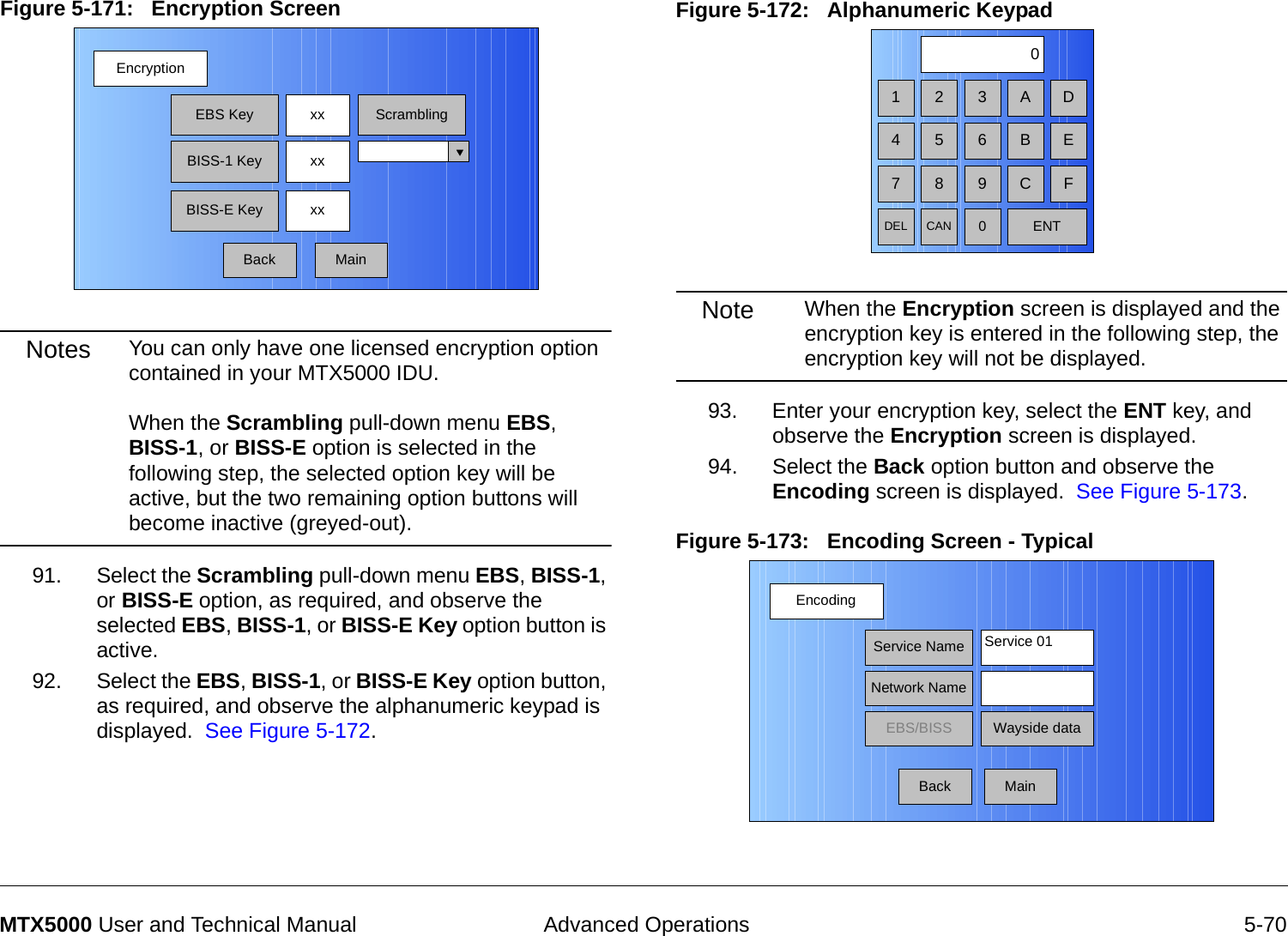
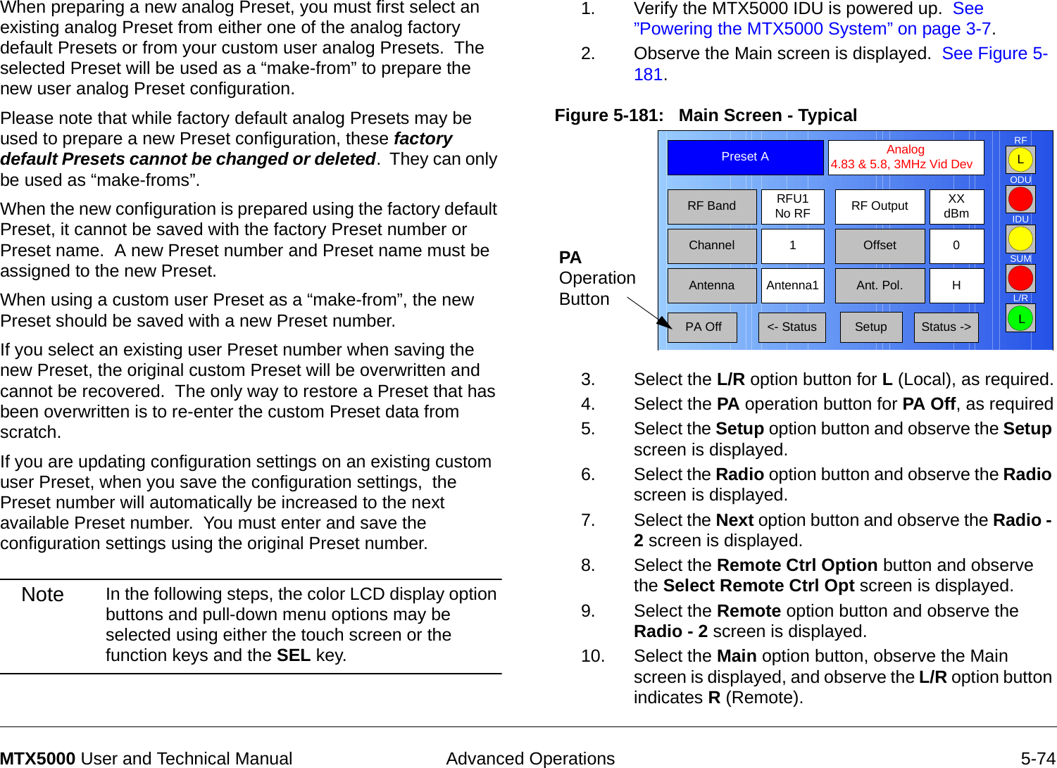
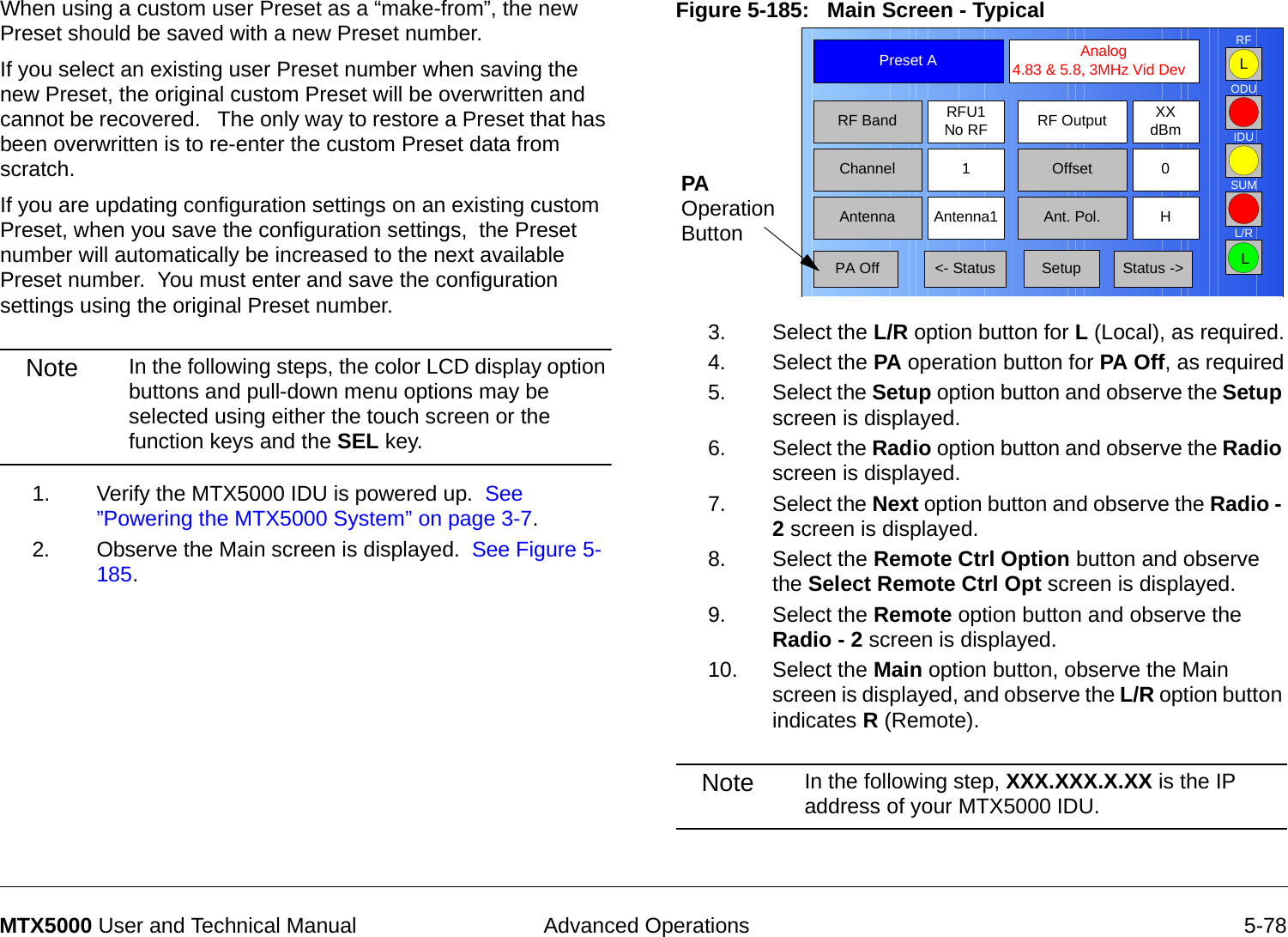
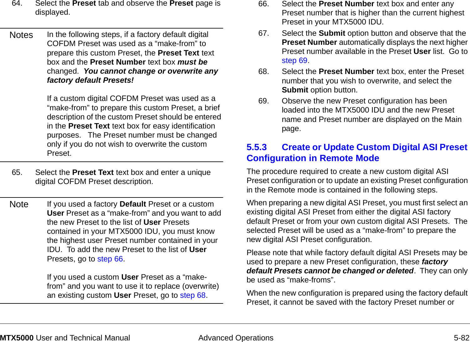
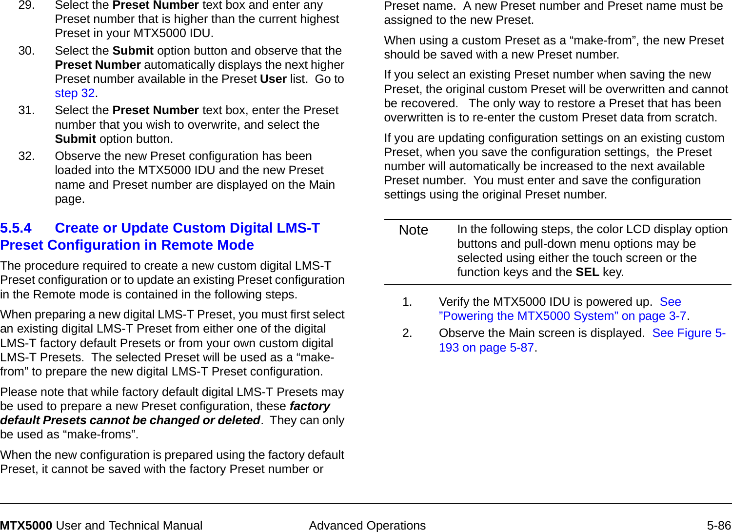
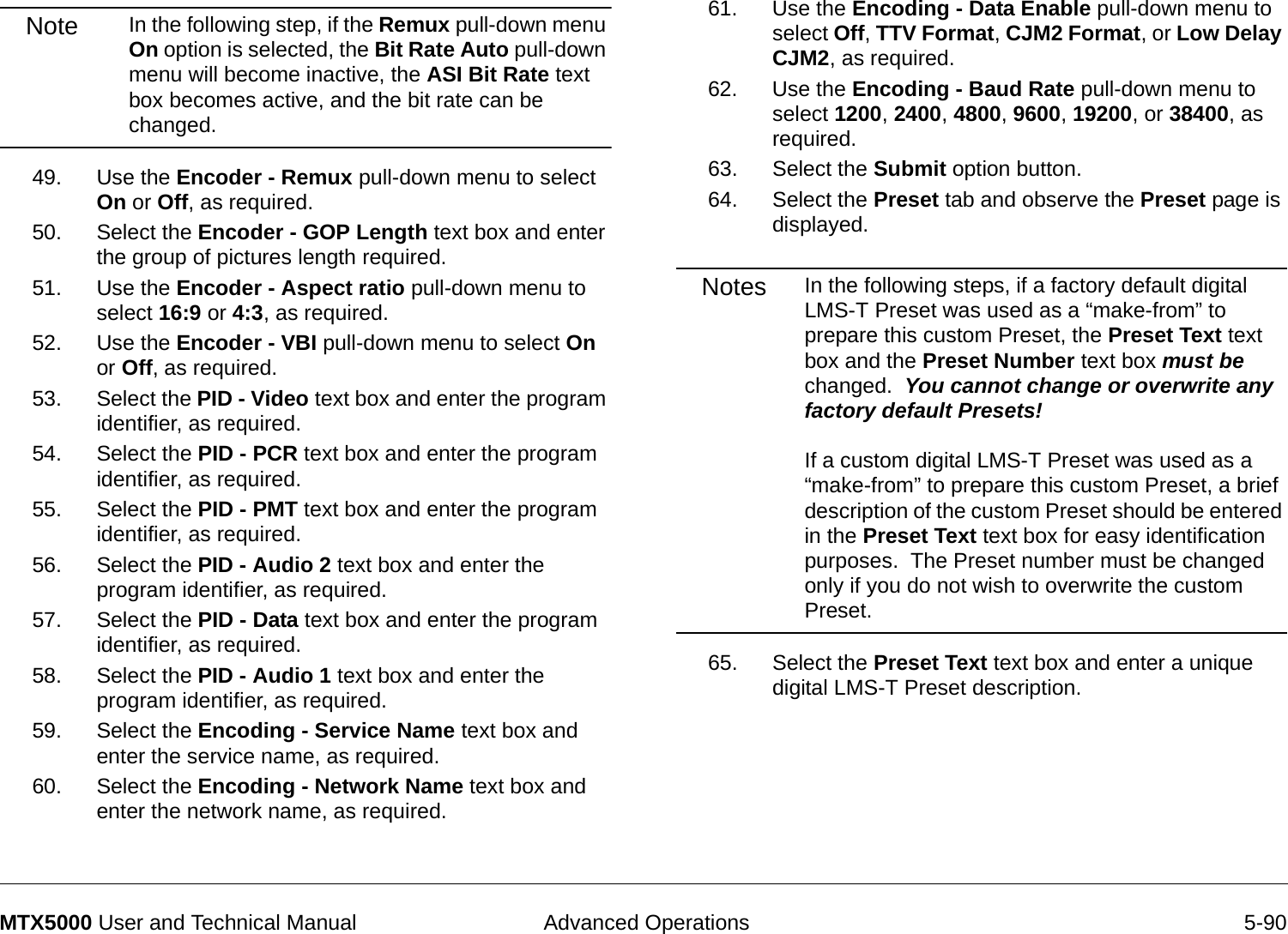
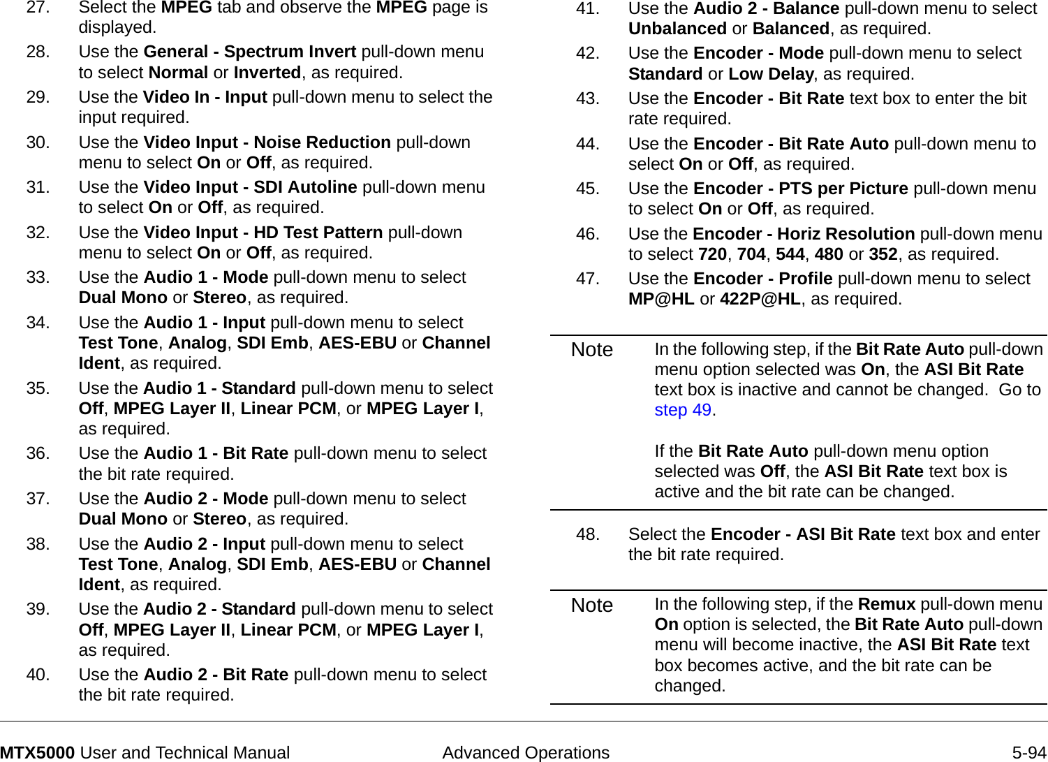


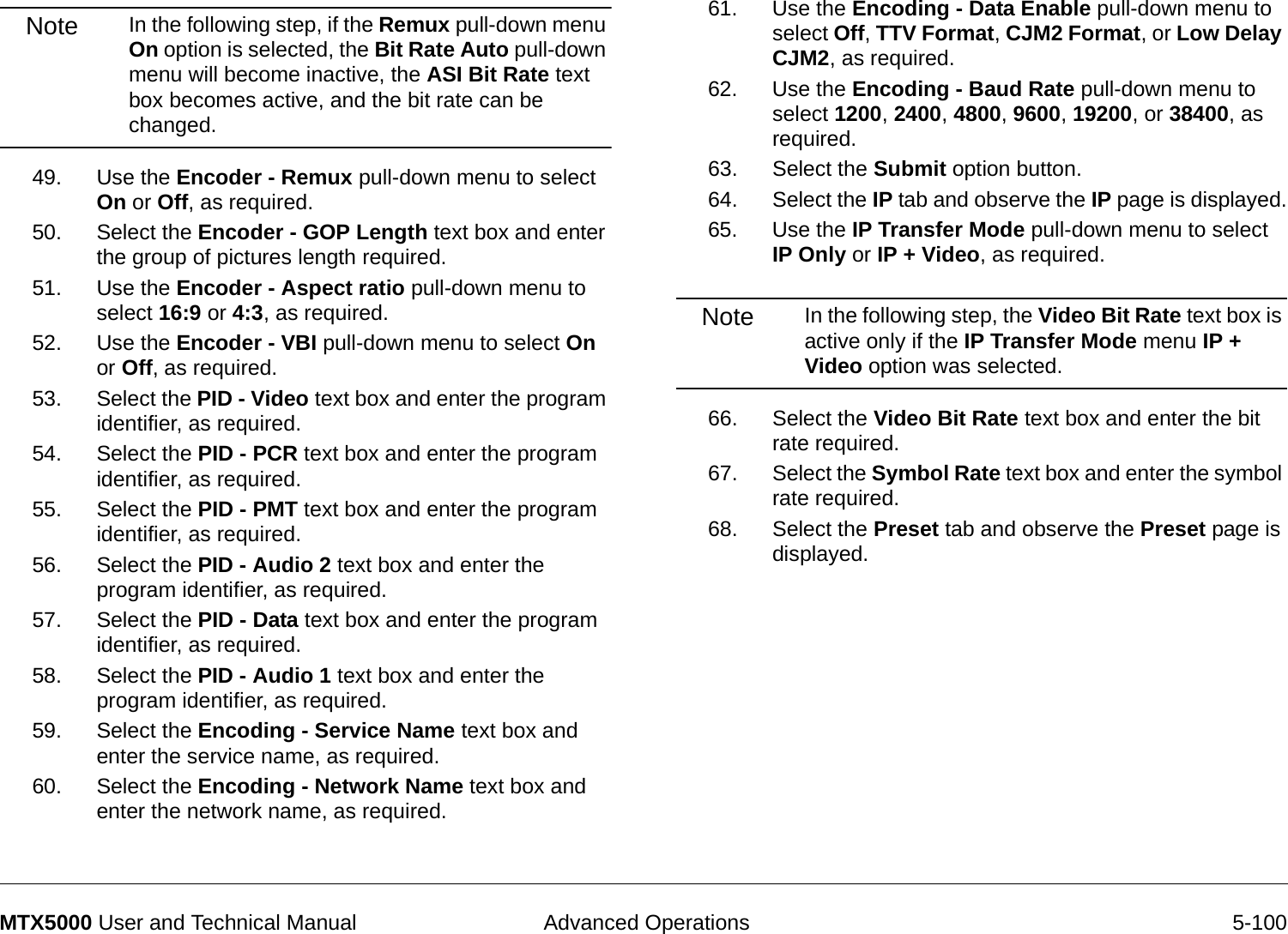
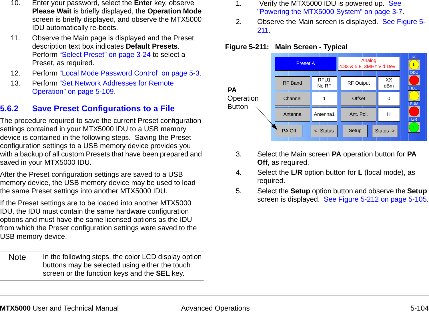
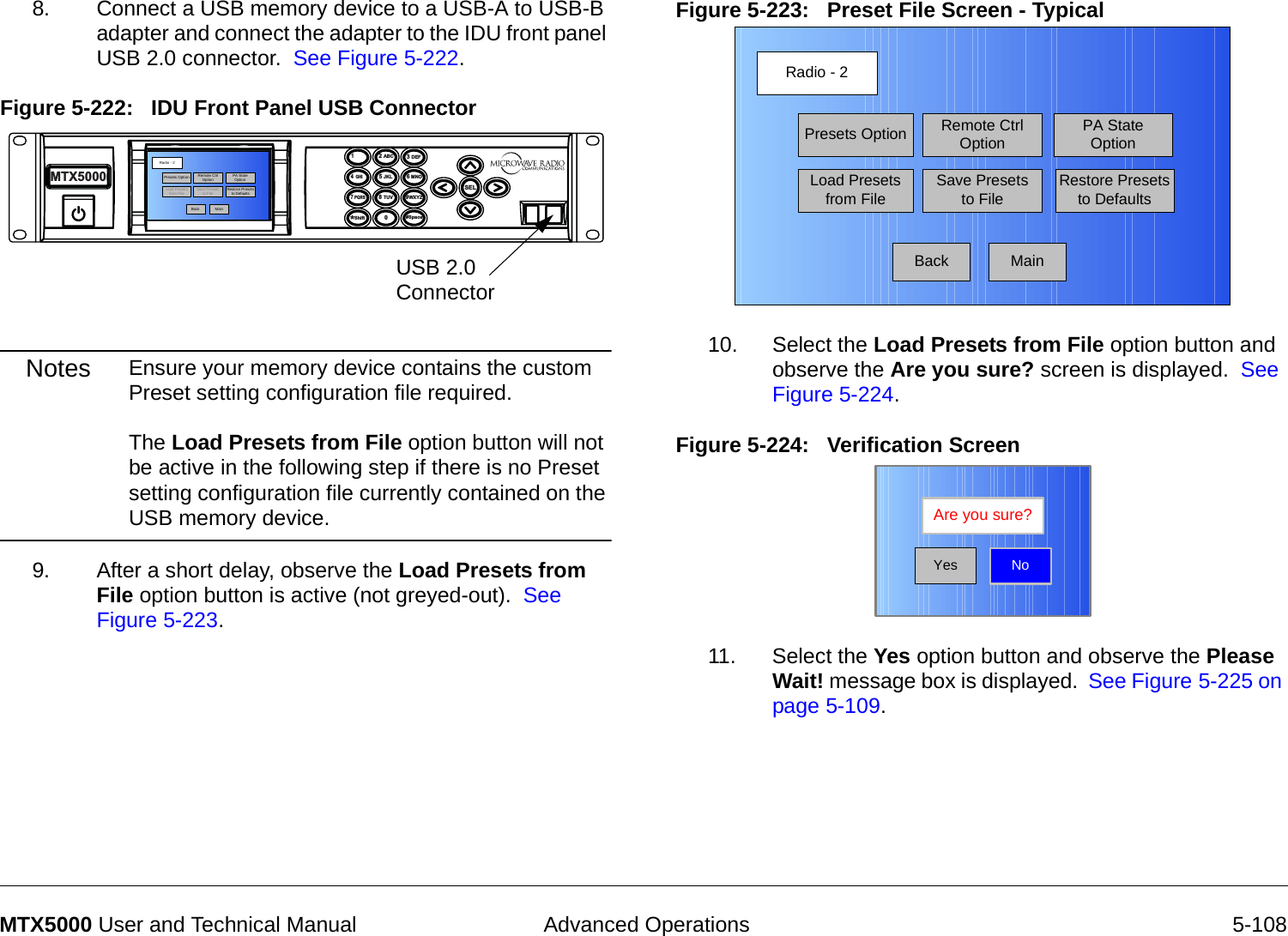
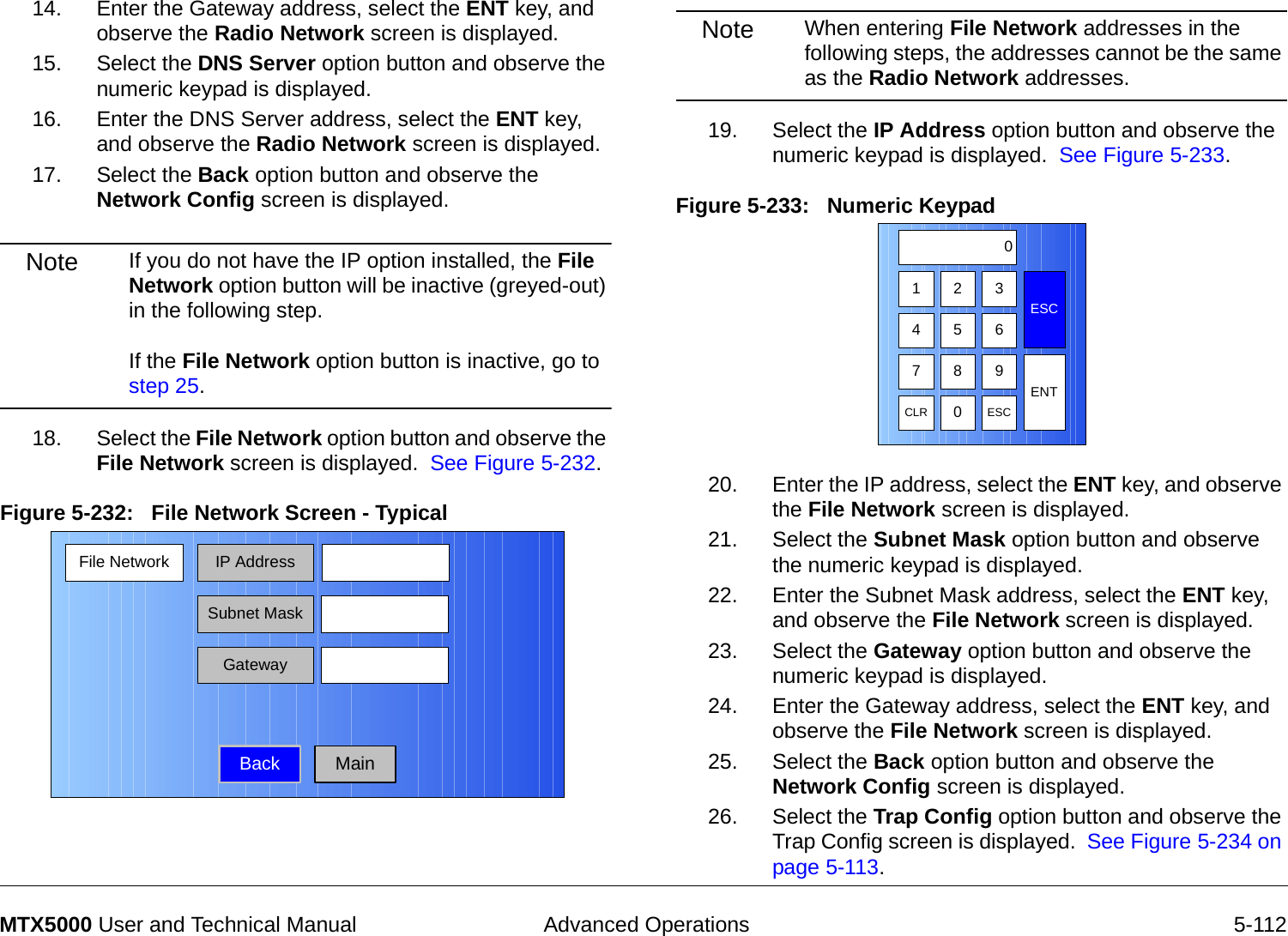
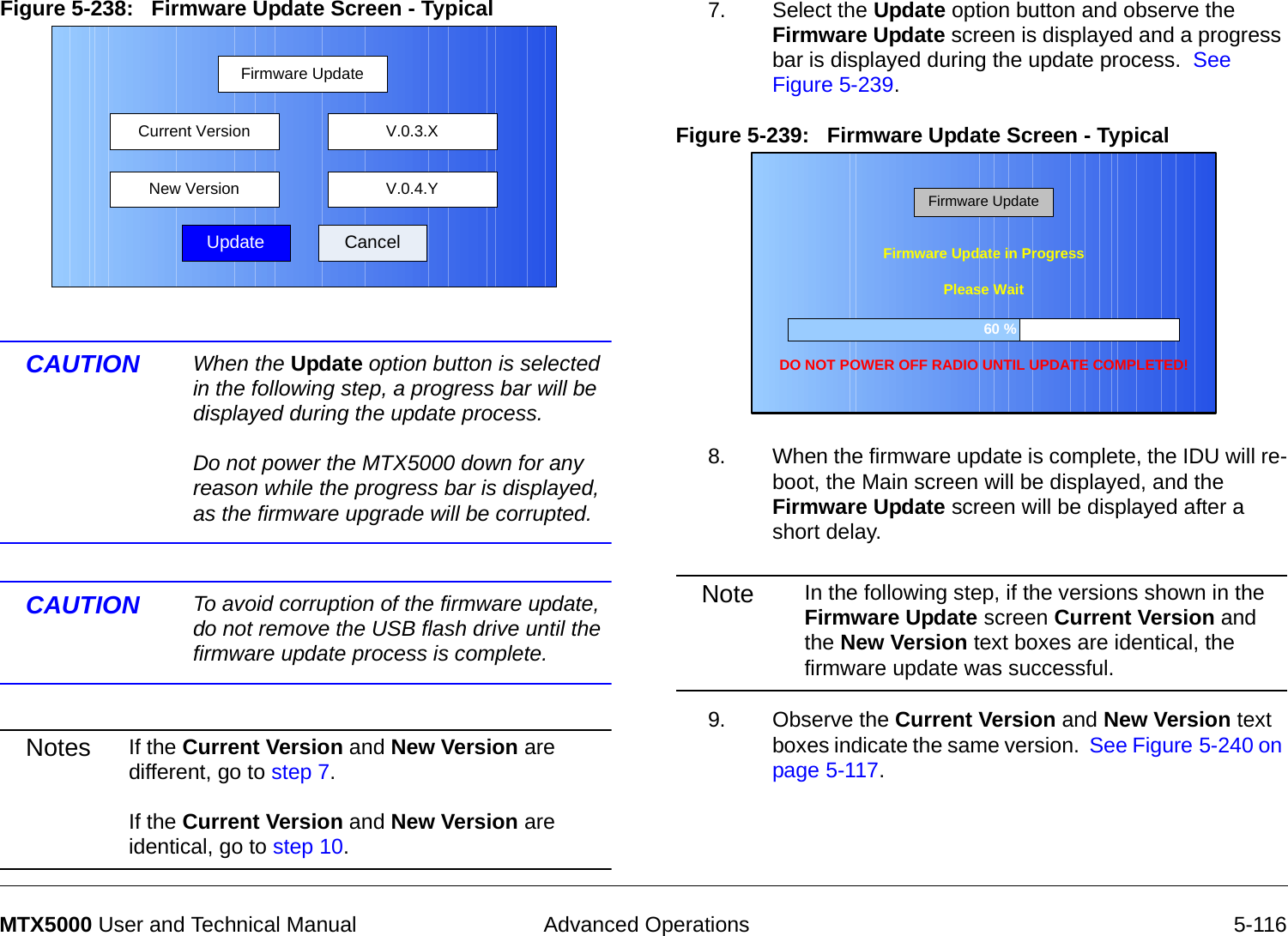
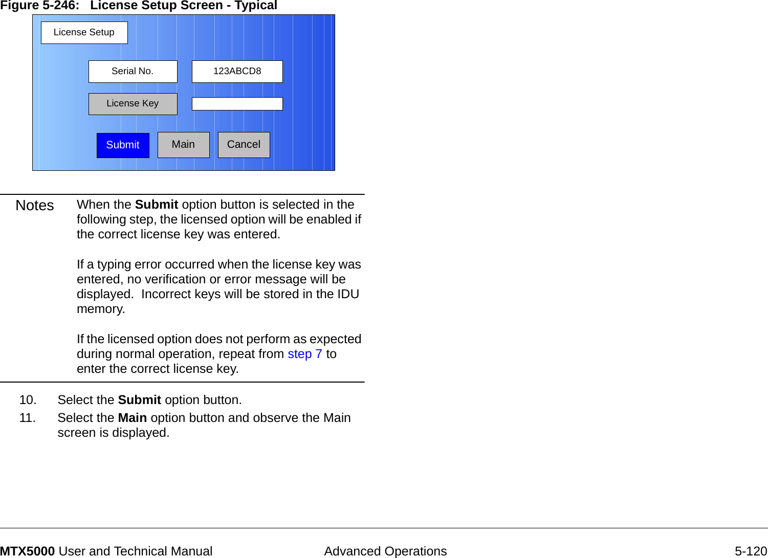
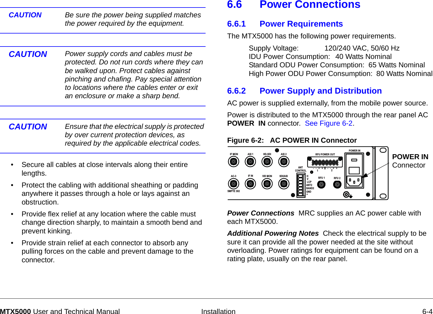
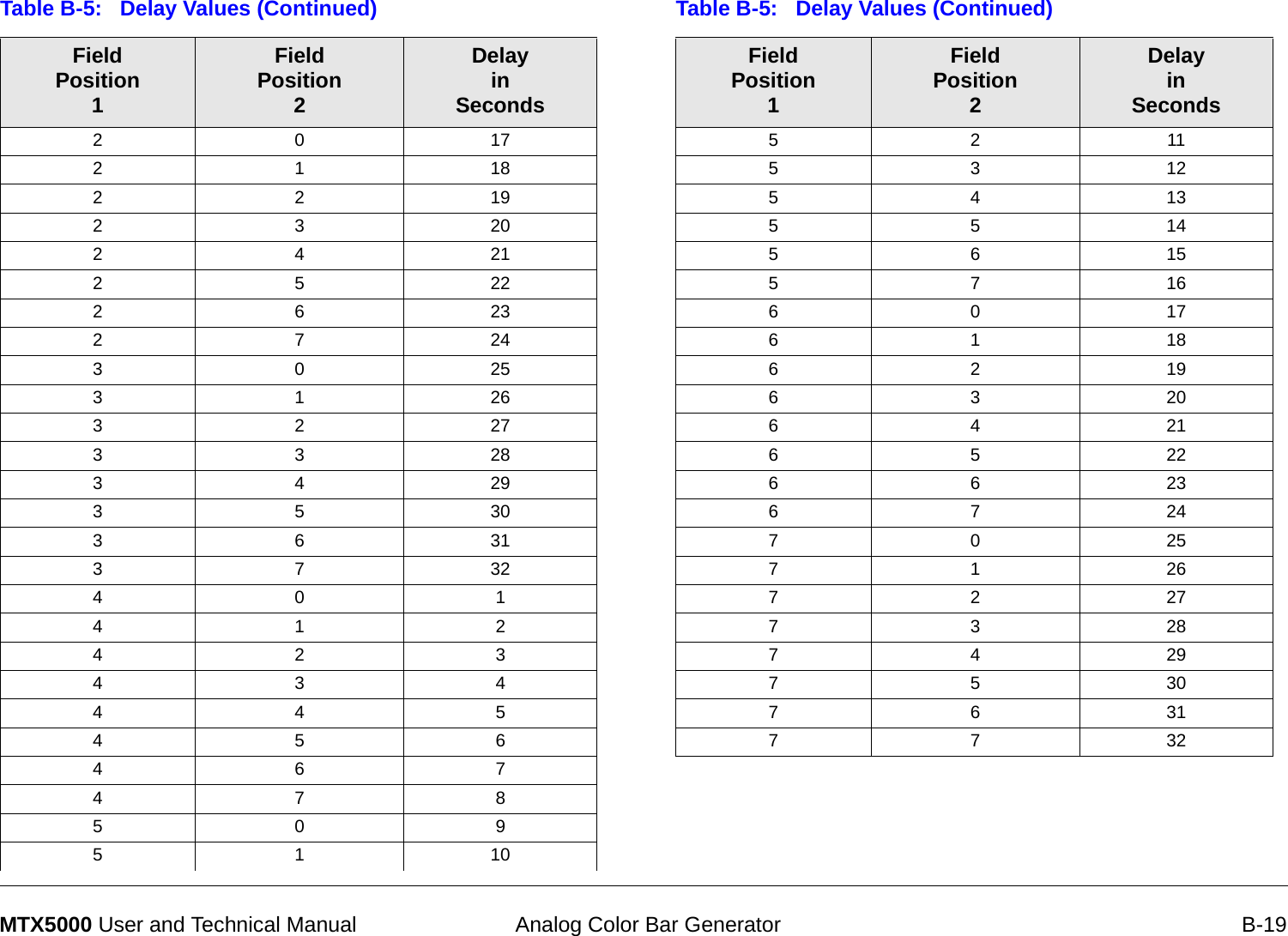
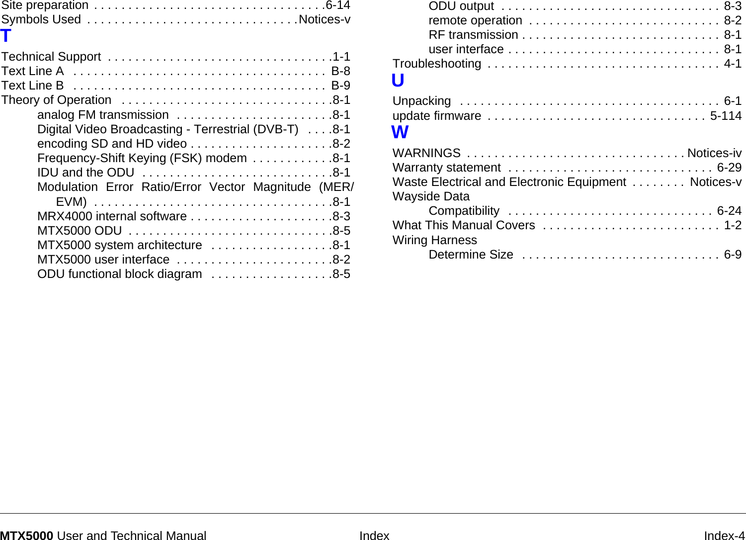
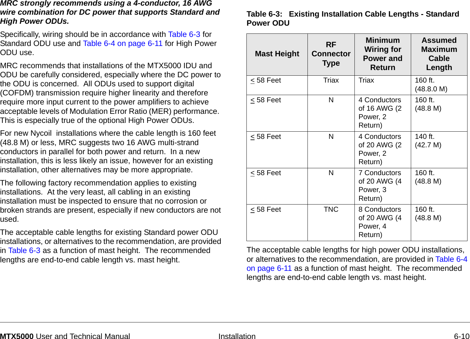
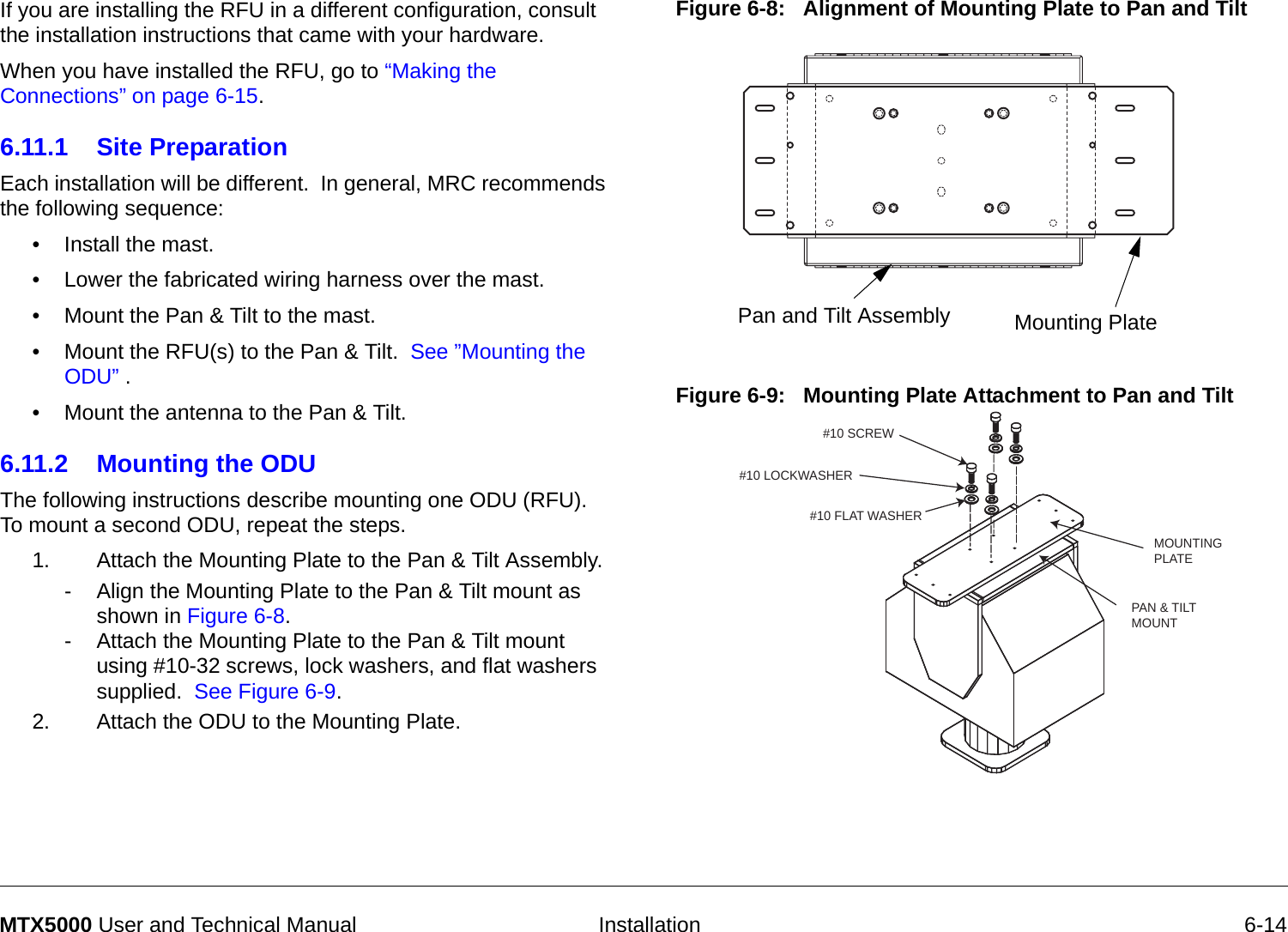
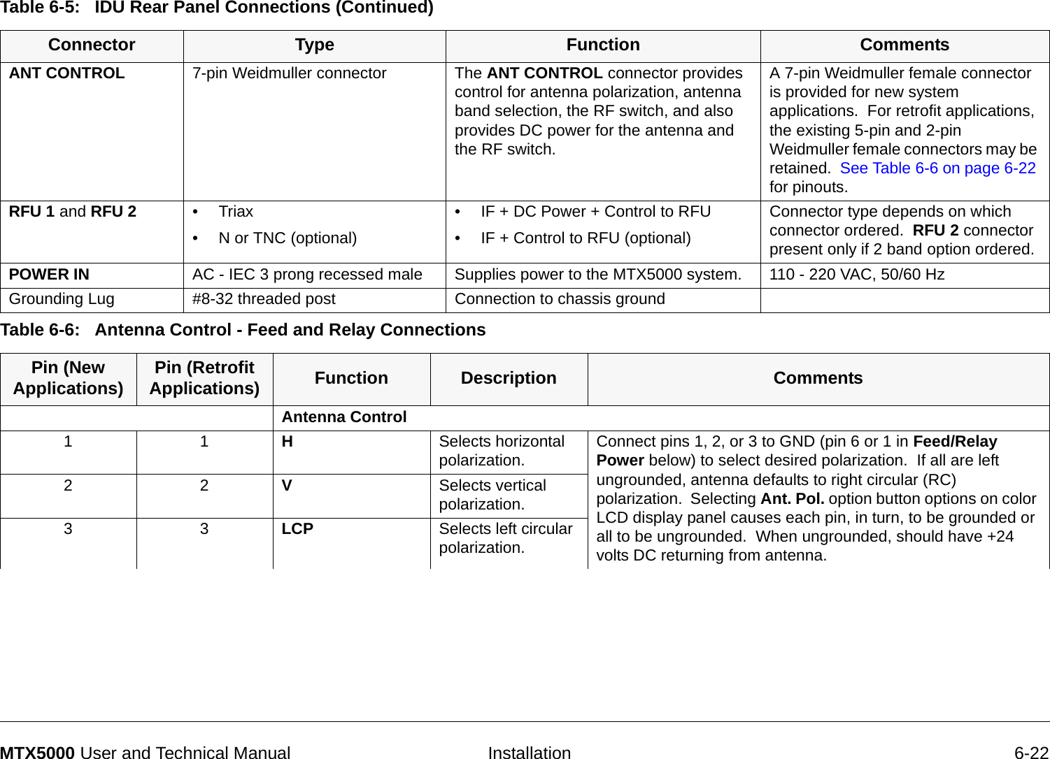
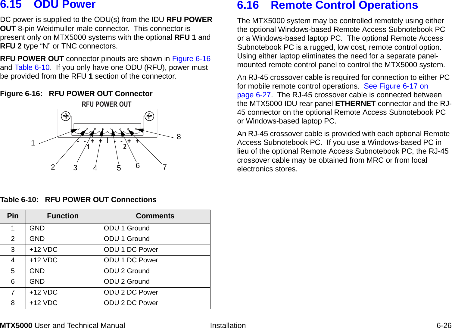
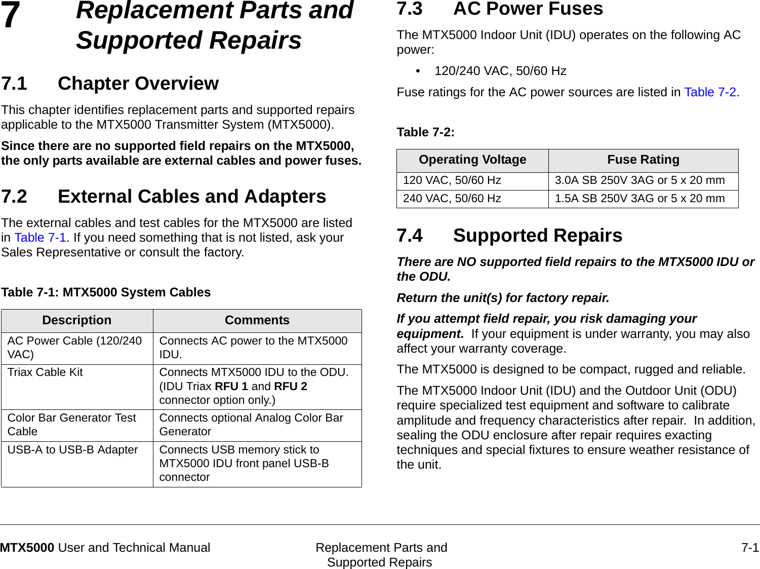
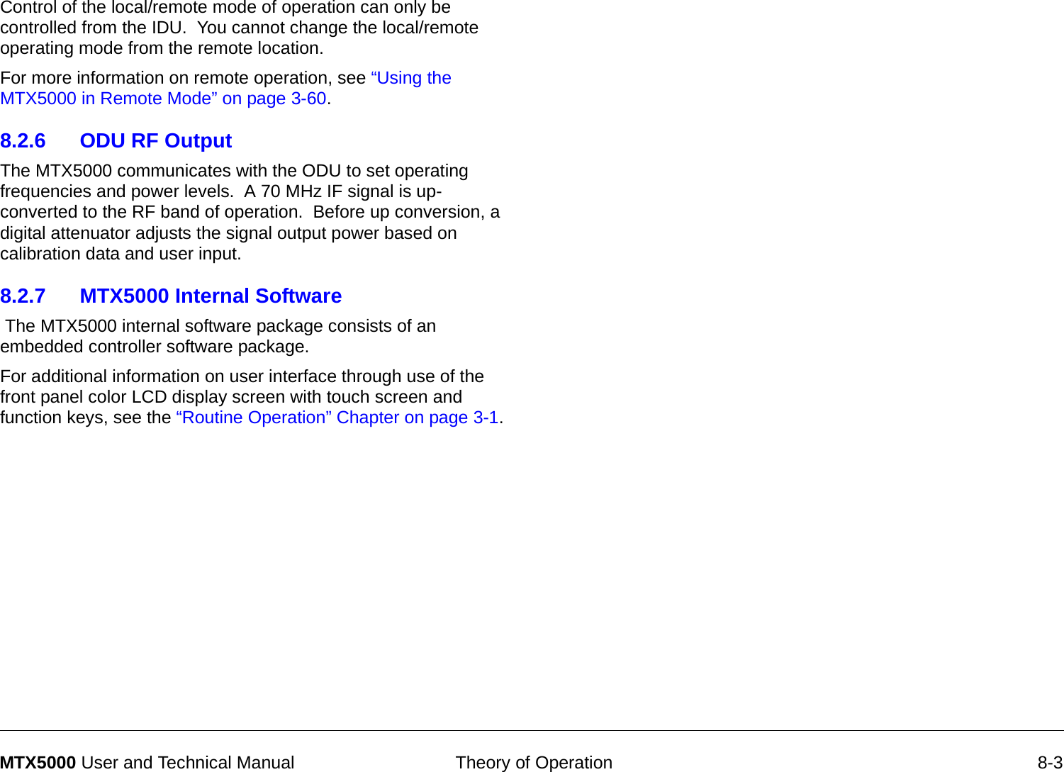
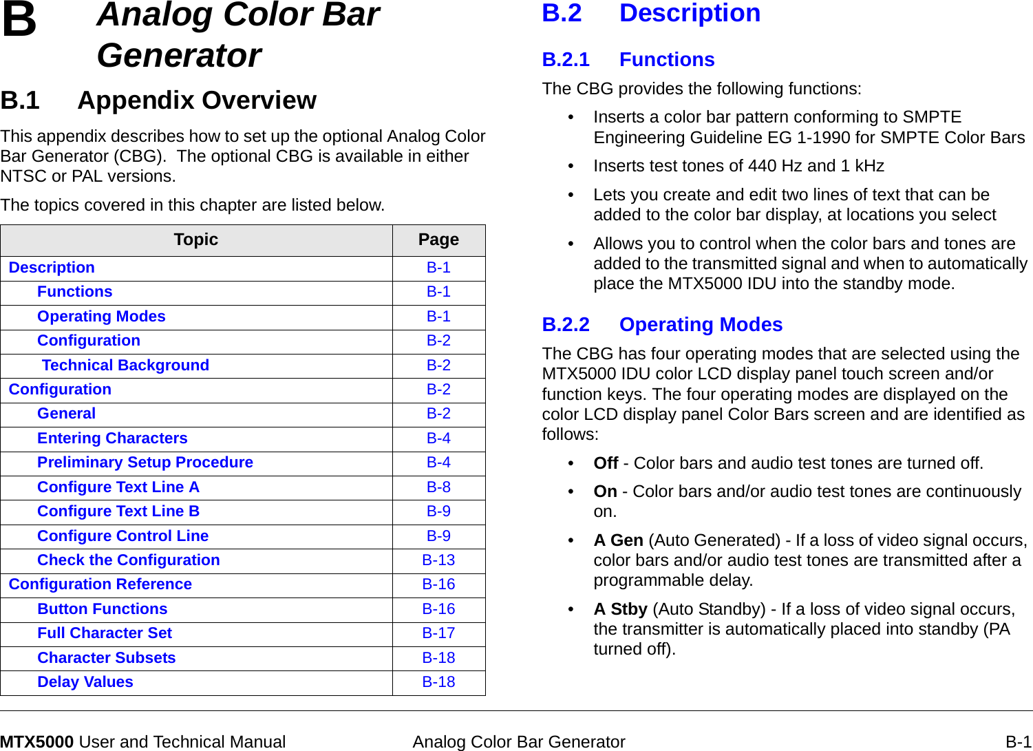
![Installation 6-8MTX5000 User and Technical Manual Table 6-1: Functions and Cables Required Function Cable Description(Vendor Part Number) Outside Diameter Inches [mm]IF + DC Power to ODUIF signal + DC Power + ODU Control TRIAX(Belden 8232) .315[8.0 mm]Antenna FunctionsAntenna Polarization Control - Single Band Operation 6 Conductor 20 AWG stranded(Manhattan M33406) .255[6.47 mm]Antenna Polarization Control - Dual Band Operation 10 Conductor 20 AWG stranded(Manhattan M33410) .335[8.5 mm]Existing Wiring IF Signal + ODU Control Coaxial, Type N Connectors(RG-214) .425[10.79 mm]2A20 POL CTL/PA200/PA700 5 Conductor 20 AWG Stranded(Belden 9445) .239[6.07 mm]Standard ODU Type N and TNC Connectors 9 Conductor 20 AWG Stranded(Belden 9455) .317[8.05 mm]High Power ODU Type N Connector 7 Conductor 16 AWG Stranded(Belden 8621) (Recommended for both Standard and High Power ODU installations).458[11.63 mm]Nycoil ConduitNycoil Conduit(Nycoil 19081) 1” [25.4 mm]Nycoil Conduit(Nycoil 20001) 1.25”[37.5 mm]](https://usermanual.wiki/Microwave-Radio-Communications/ODU2ATXADH.Manual-Part-2/User-Guide-1220284-Page-102.png)
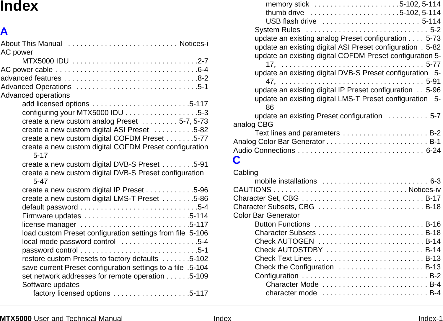
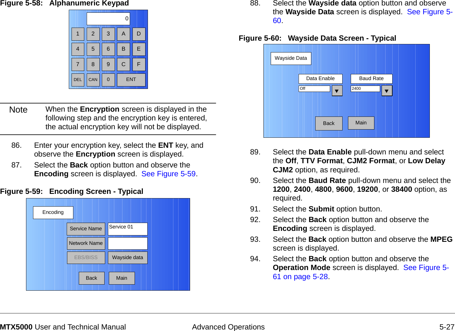
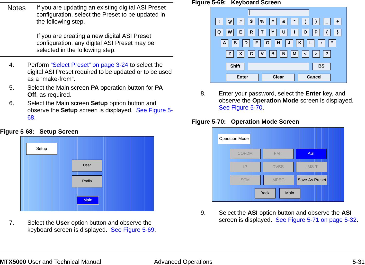
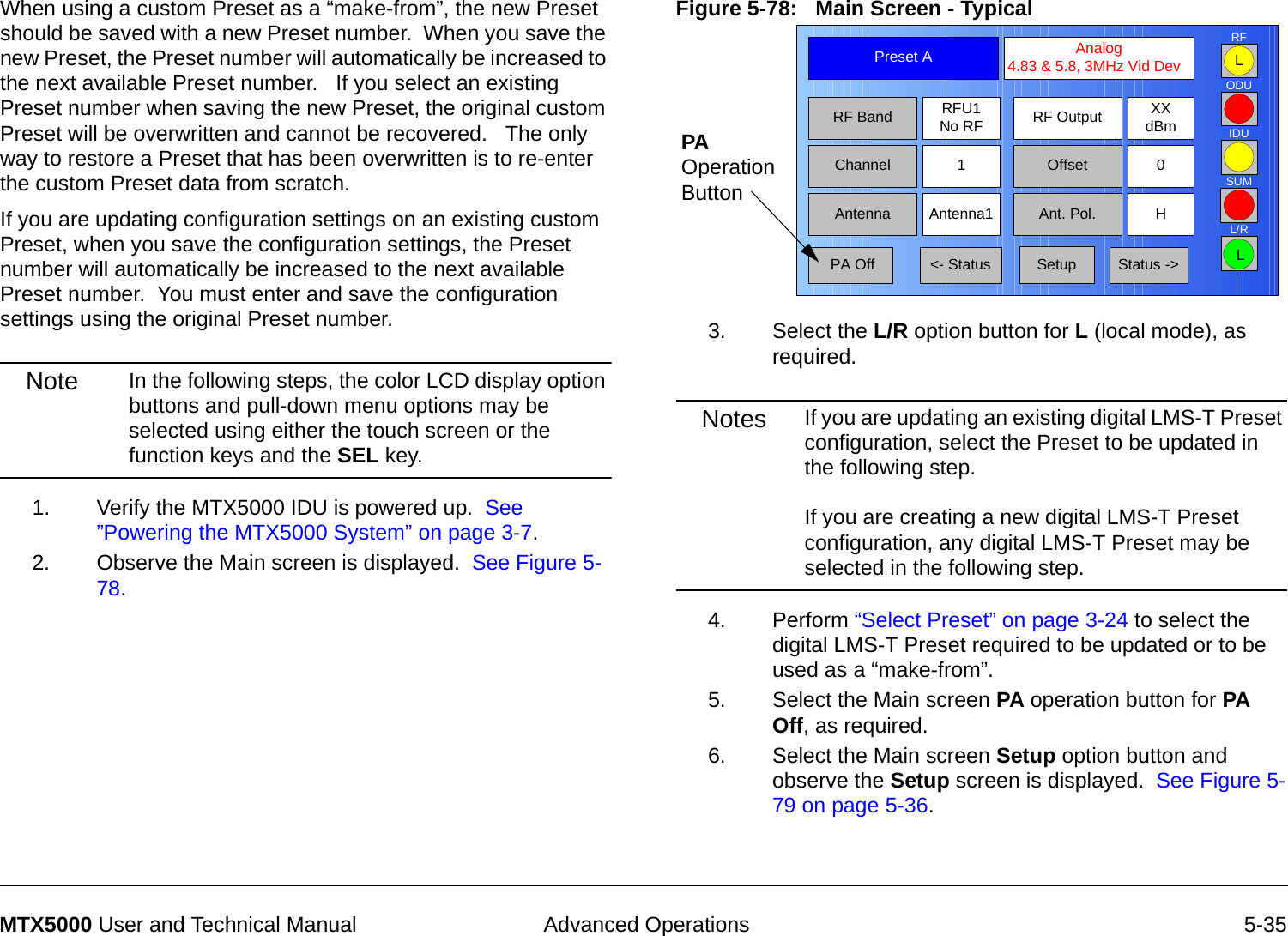
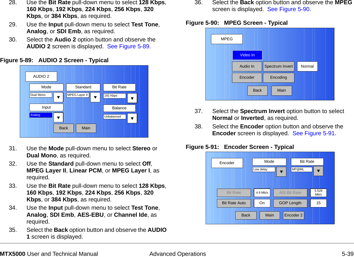
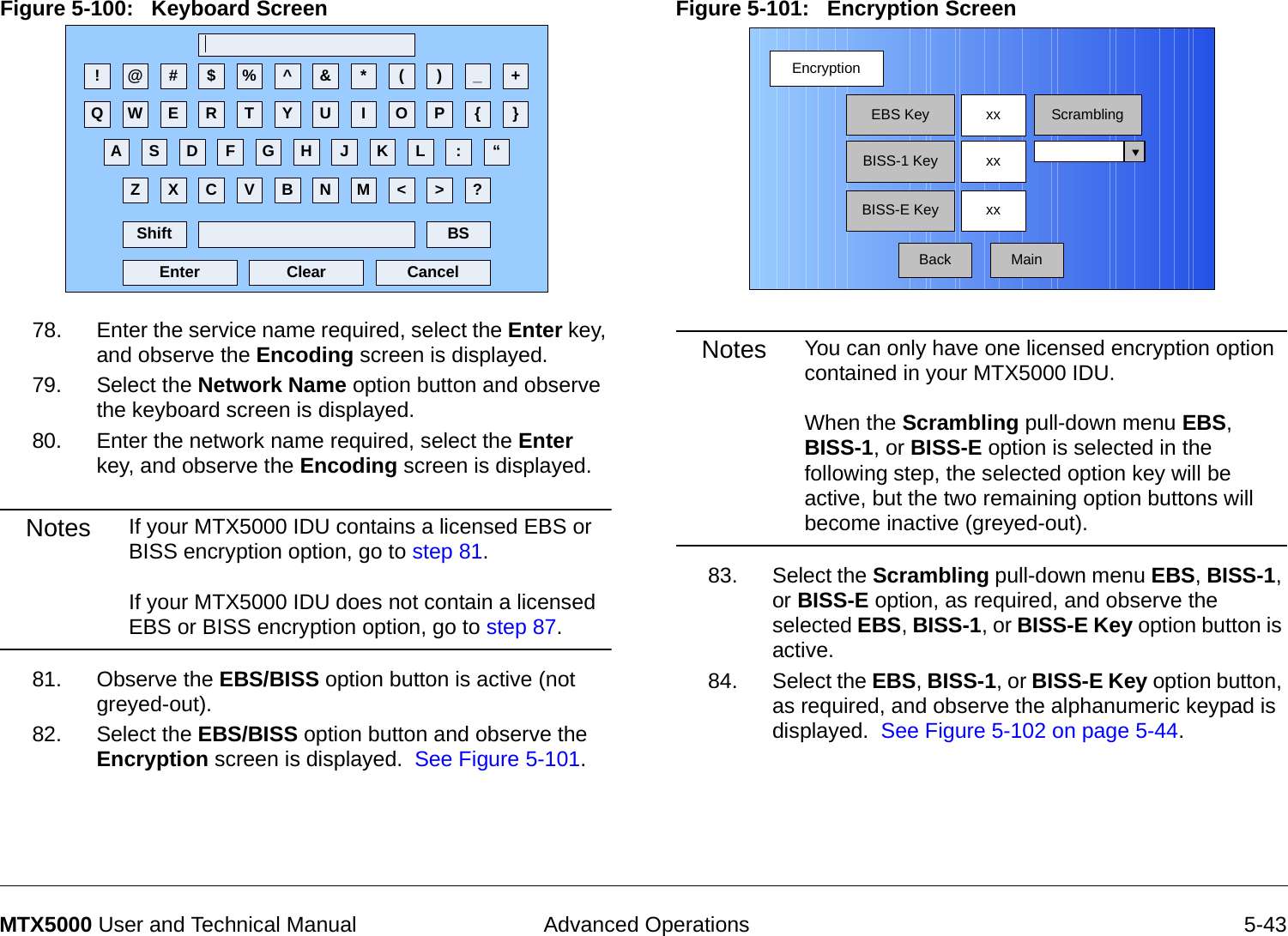
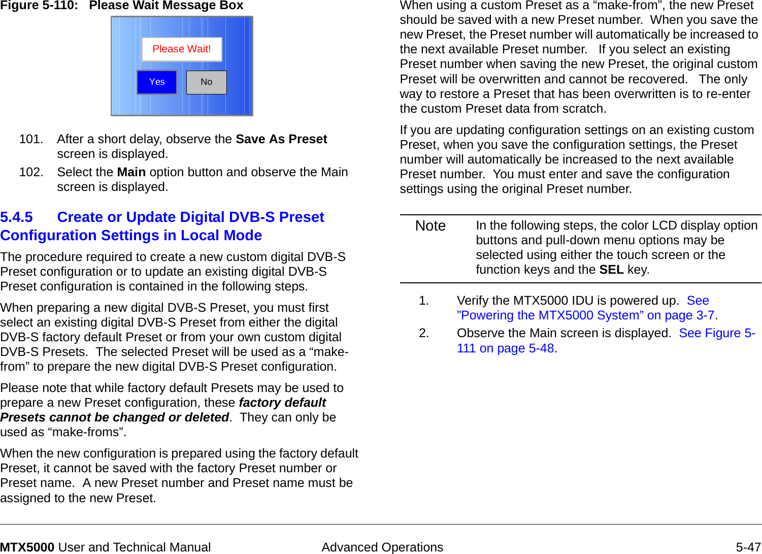
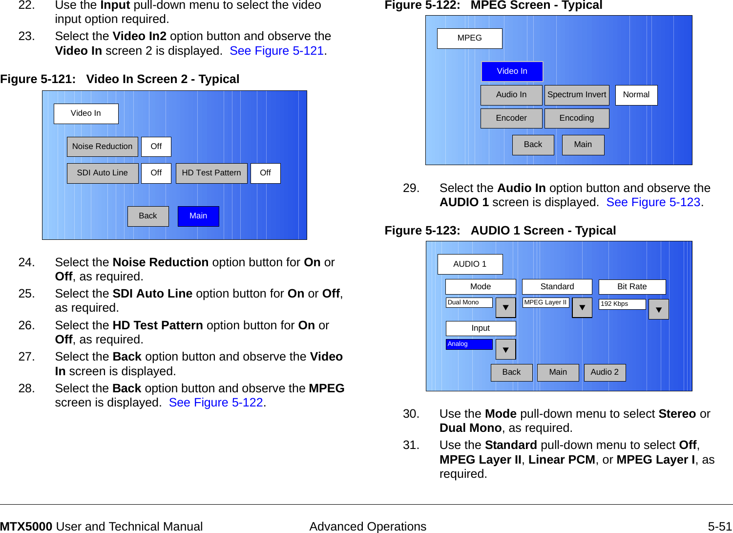
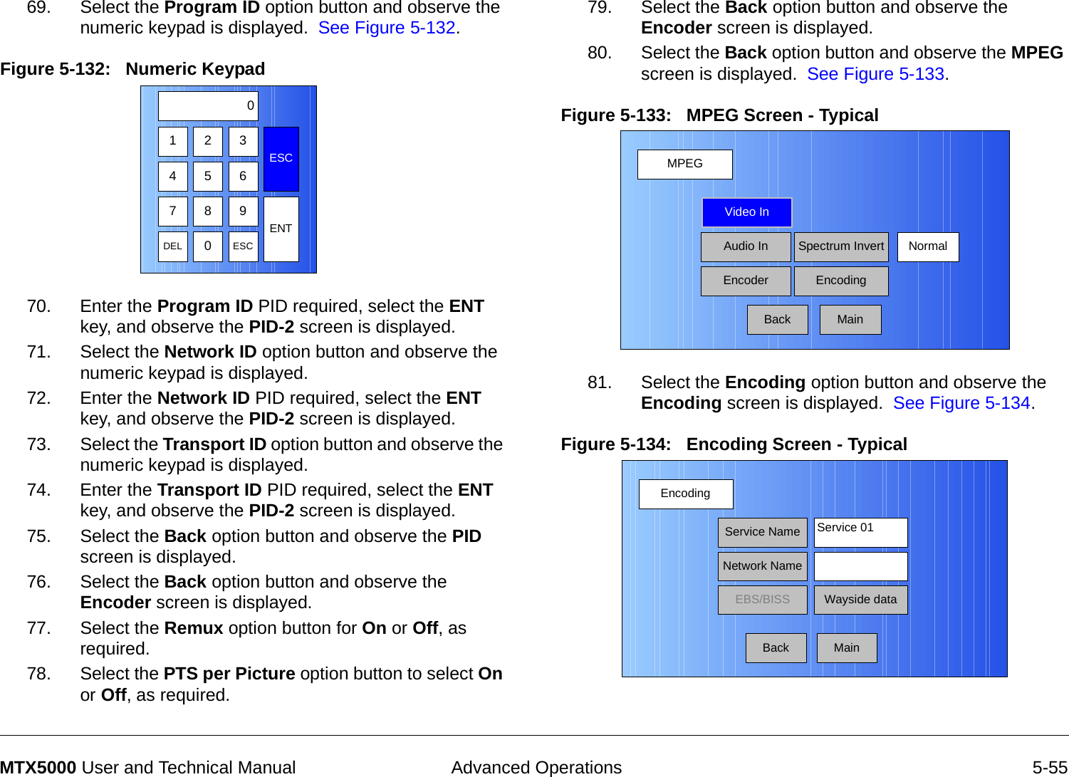
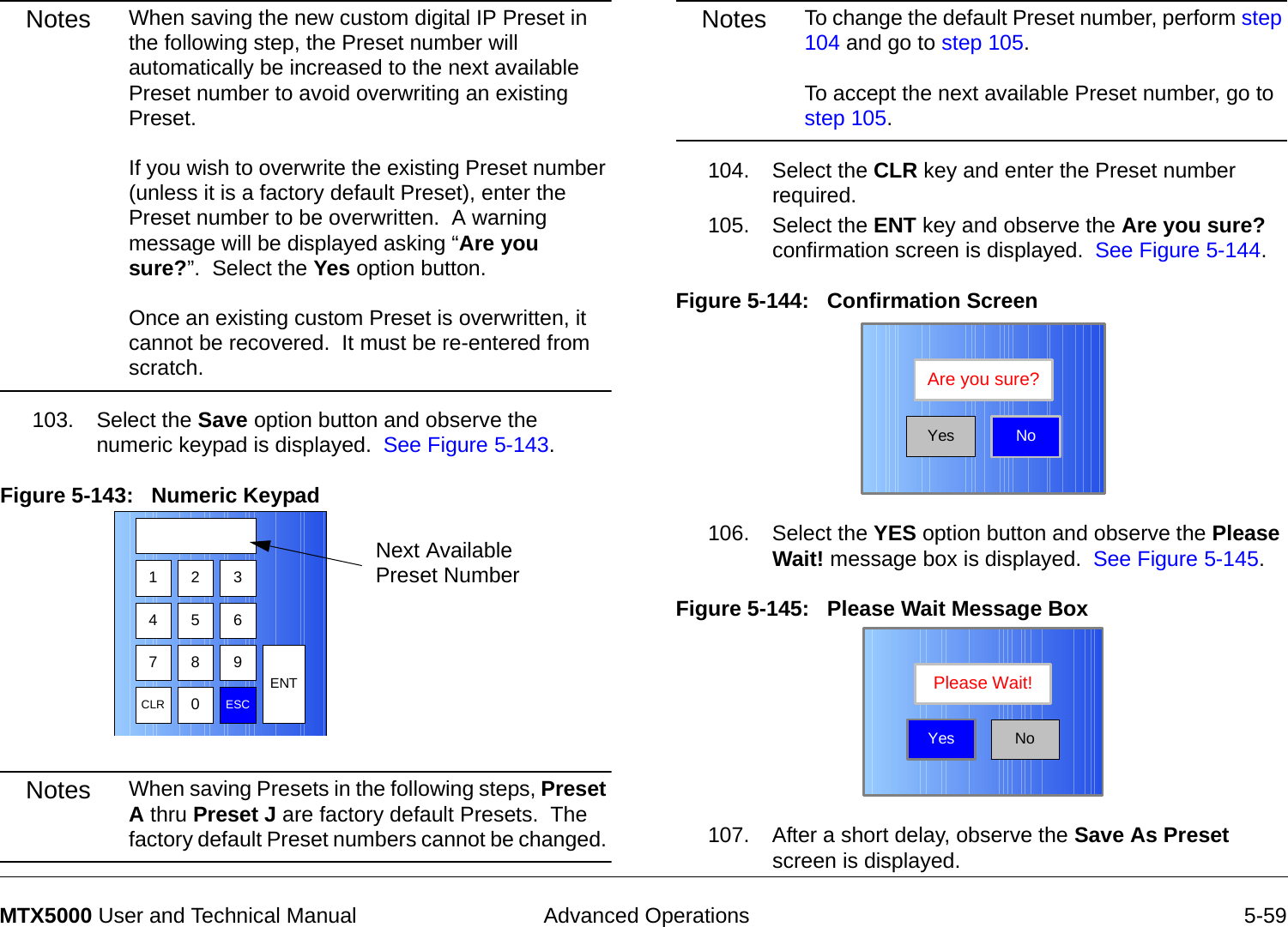
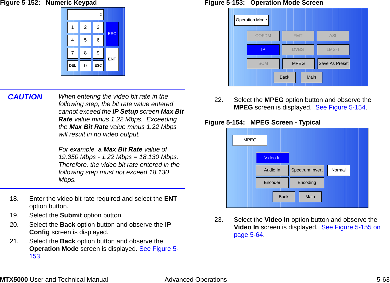
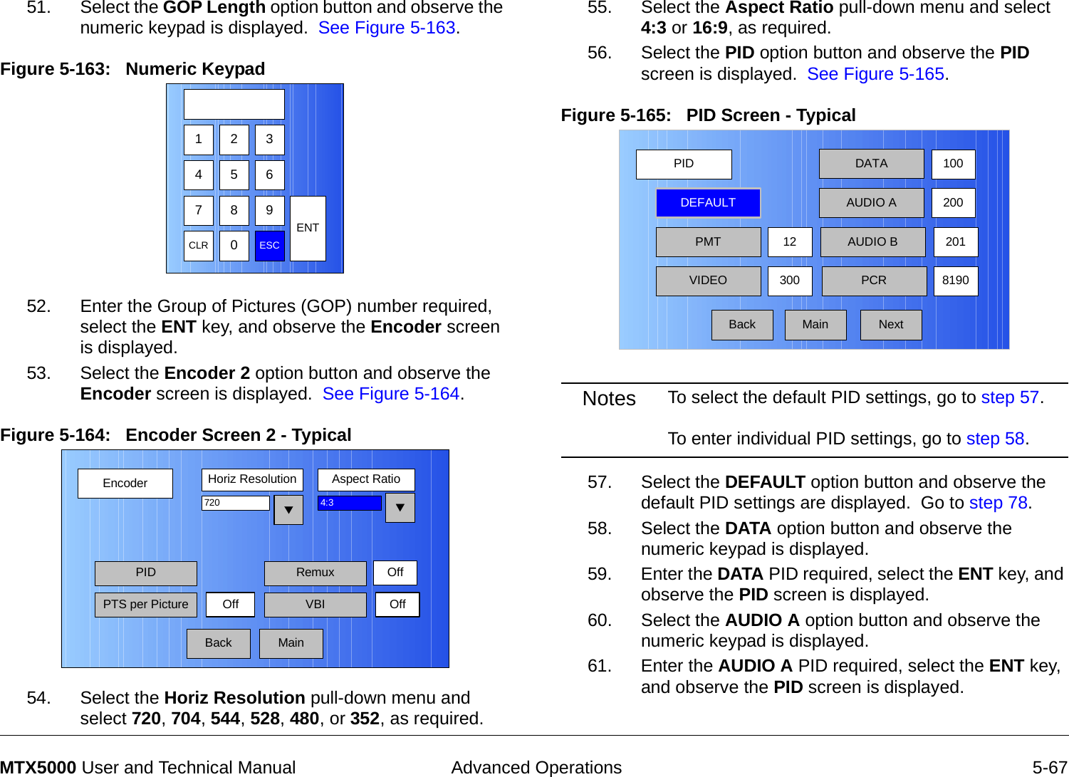
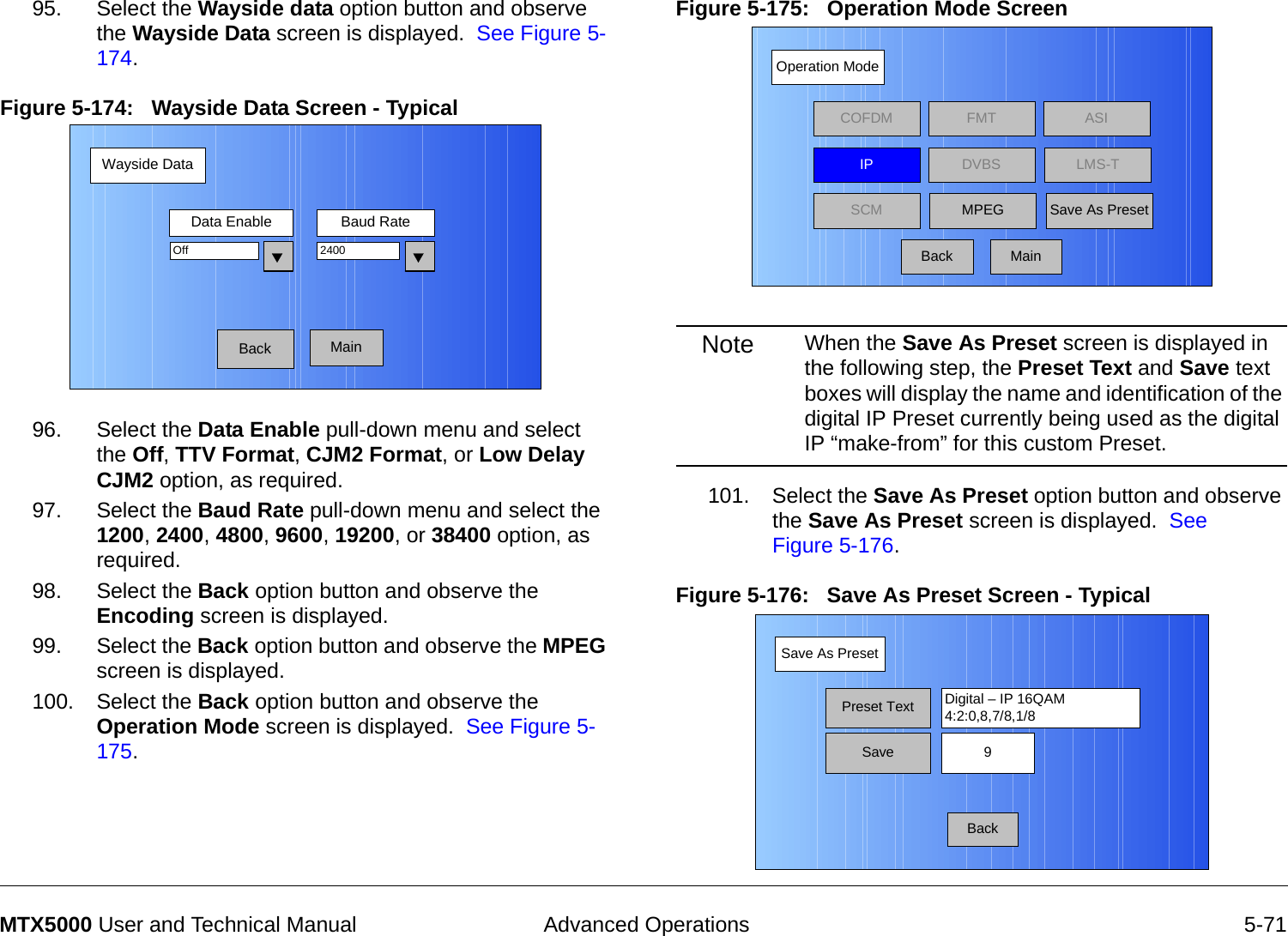
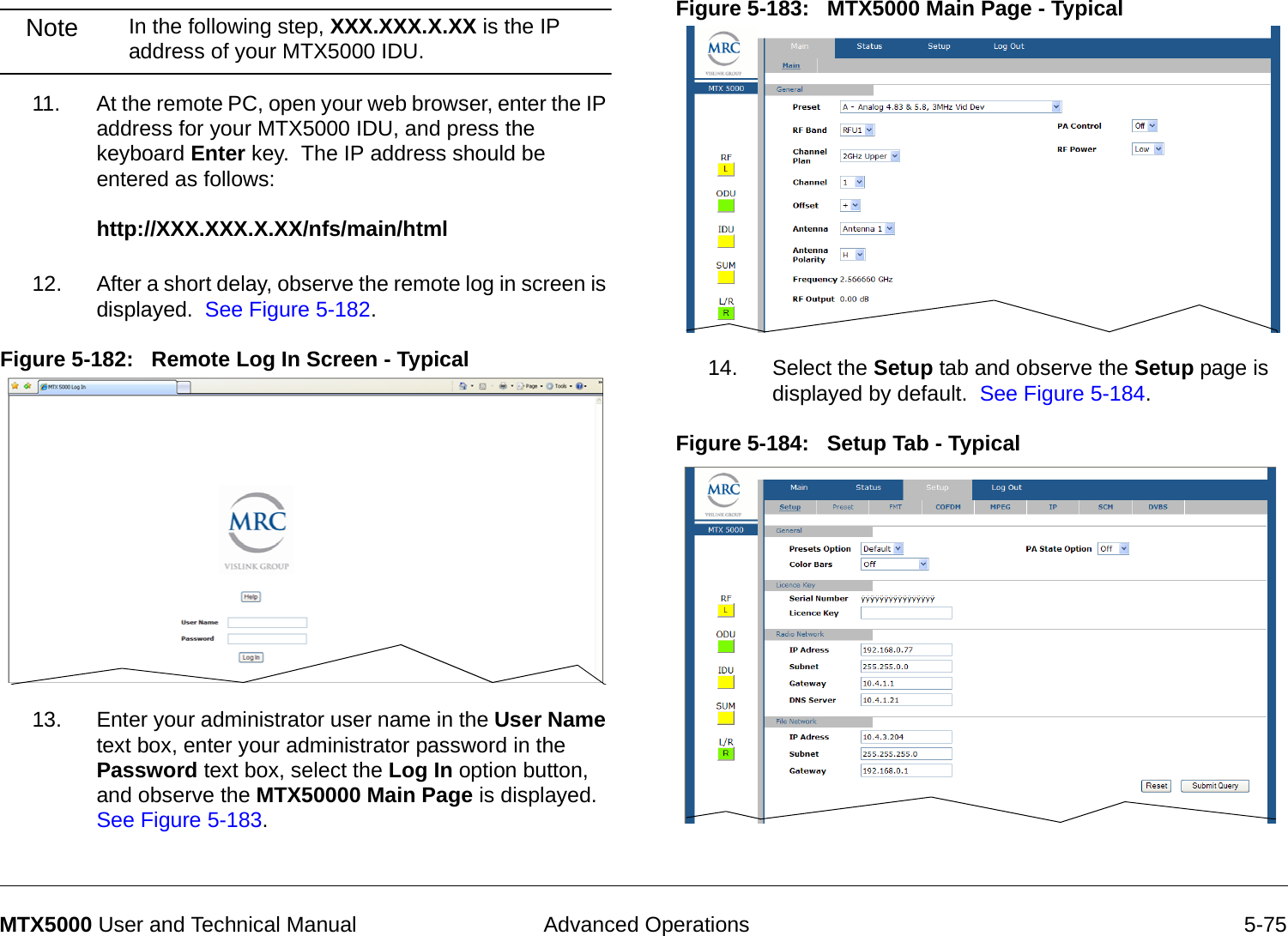
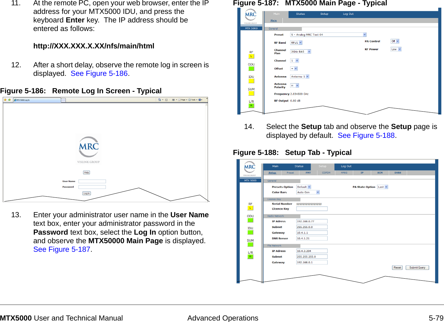
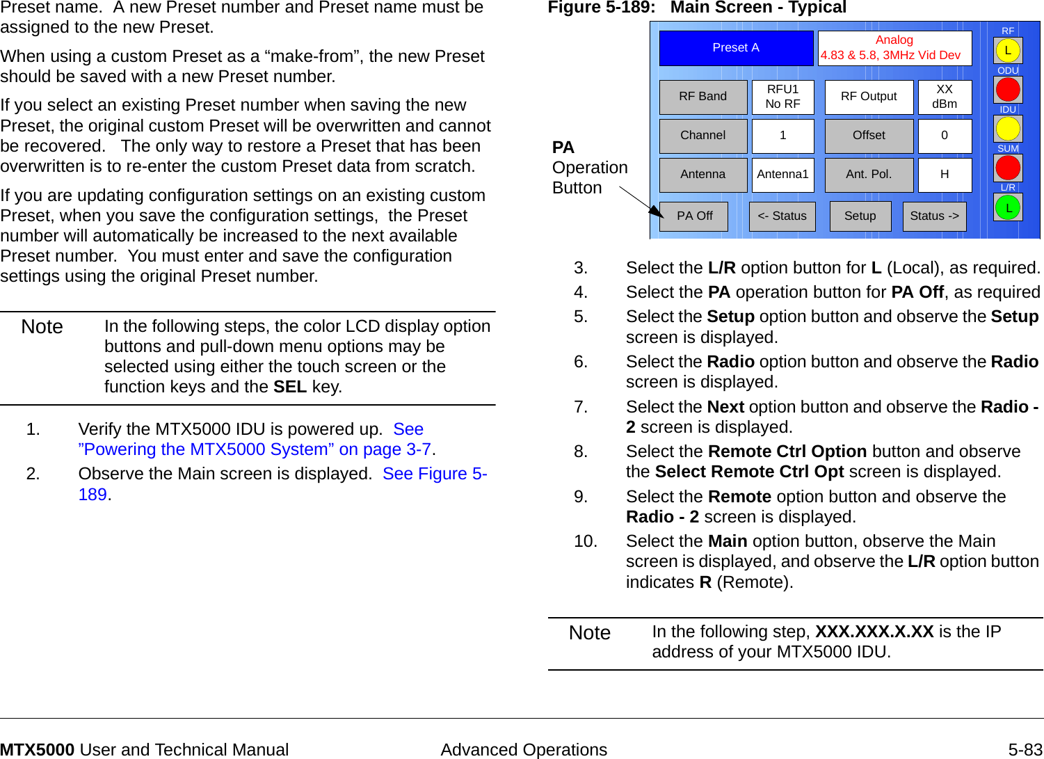
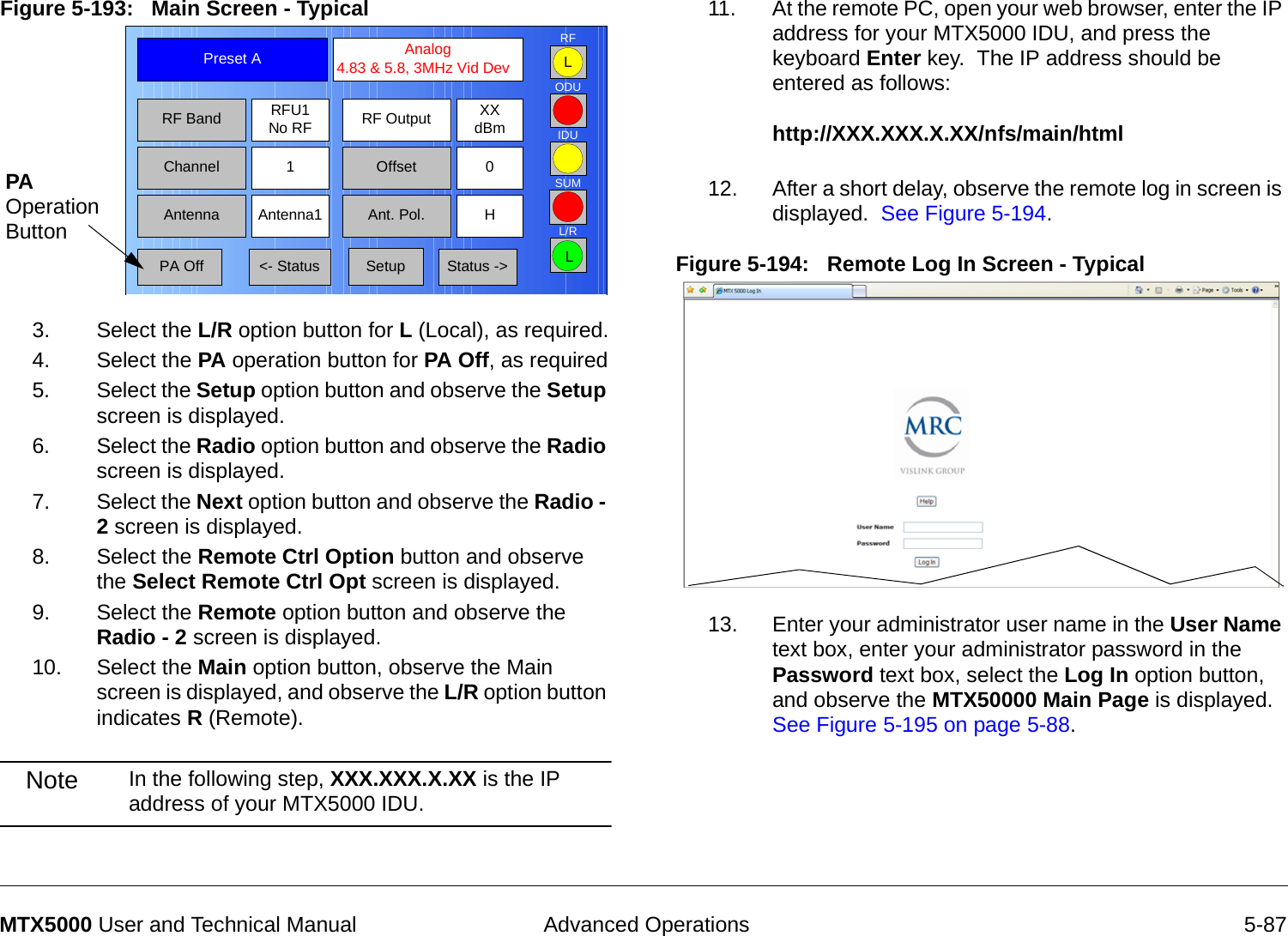
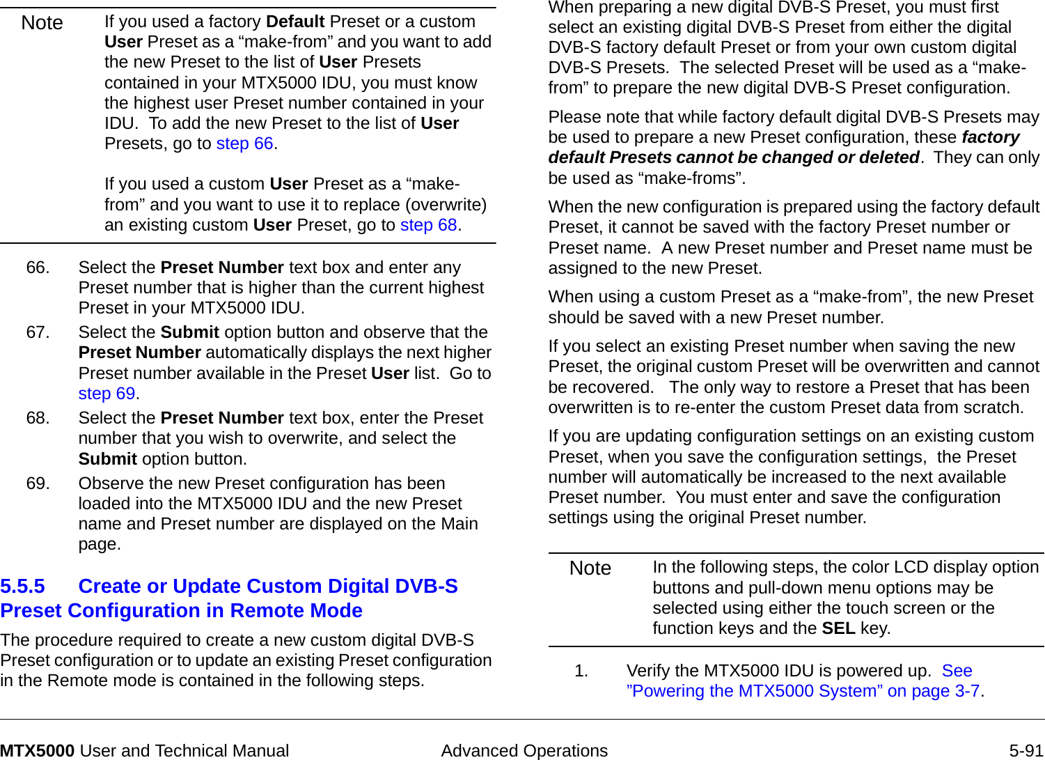
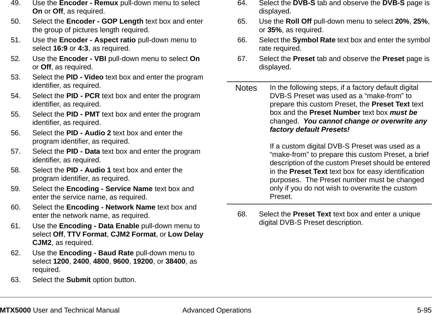
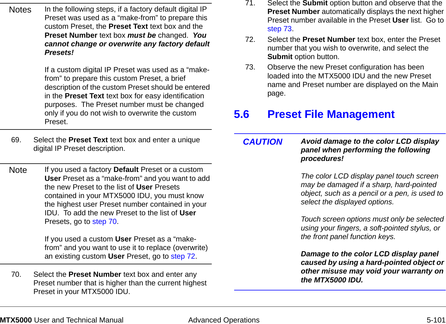
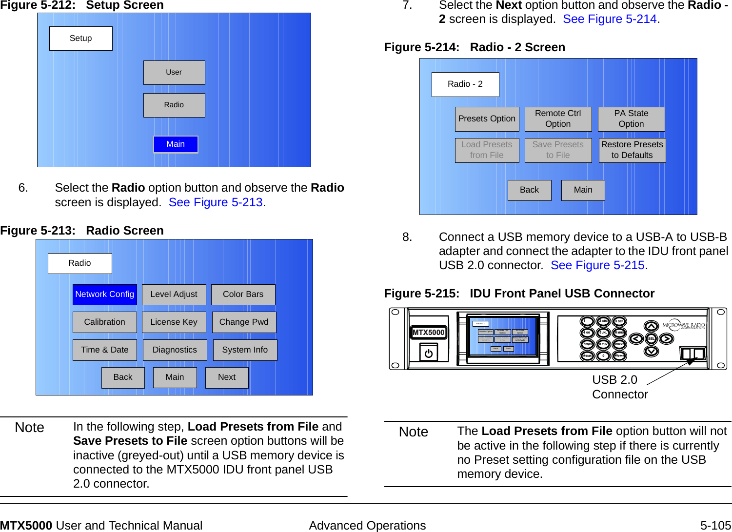
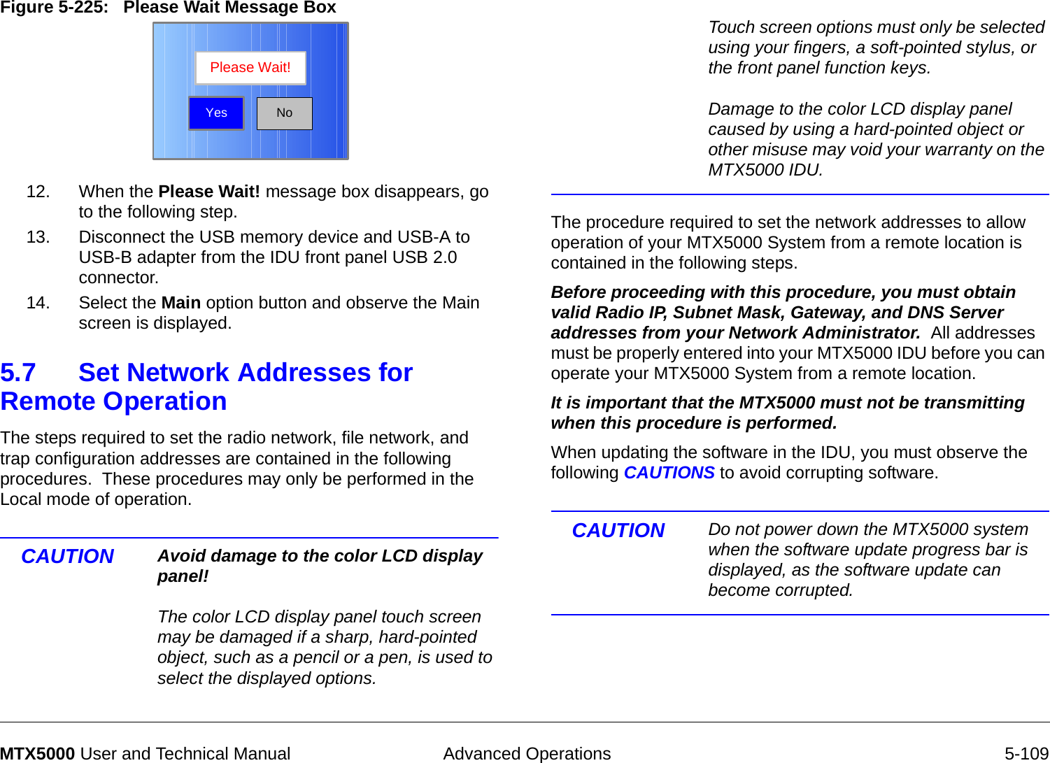
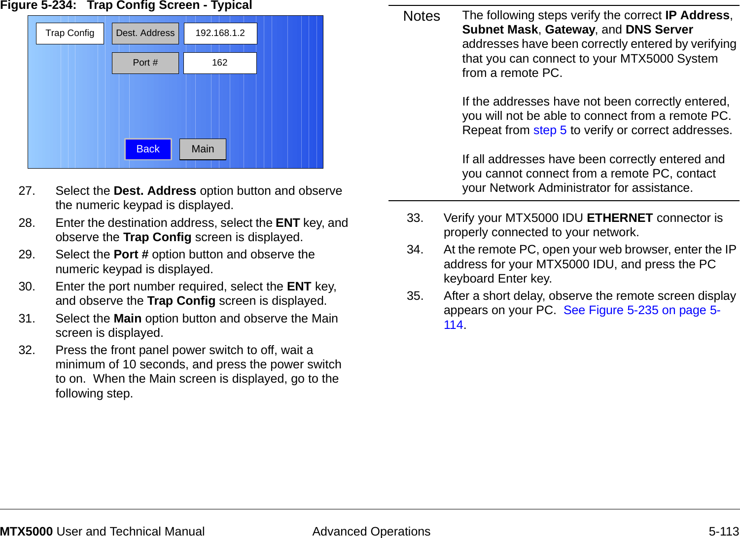
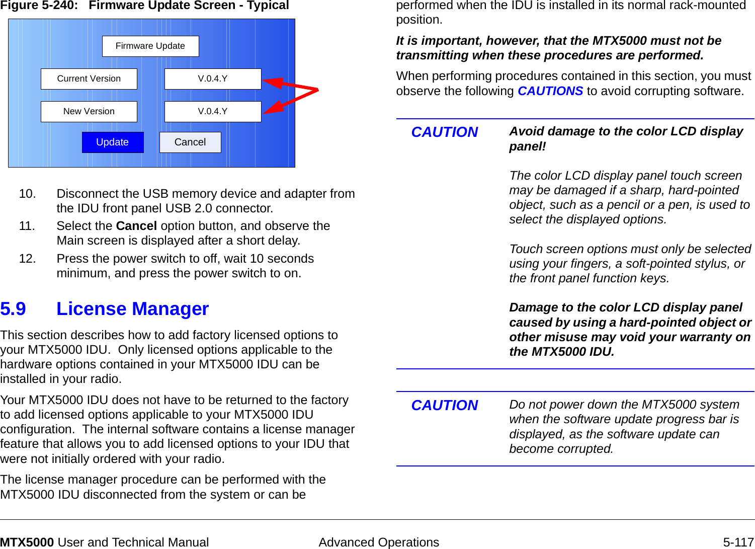
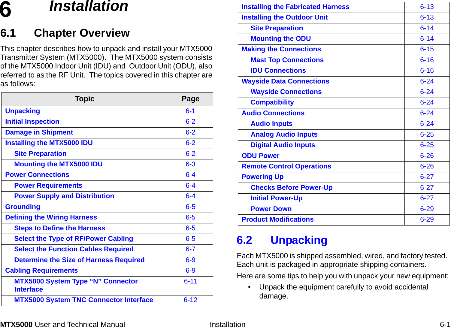
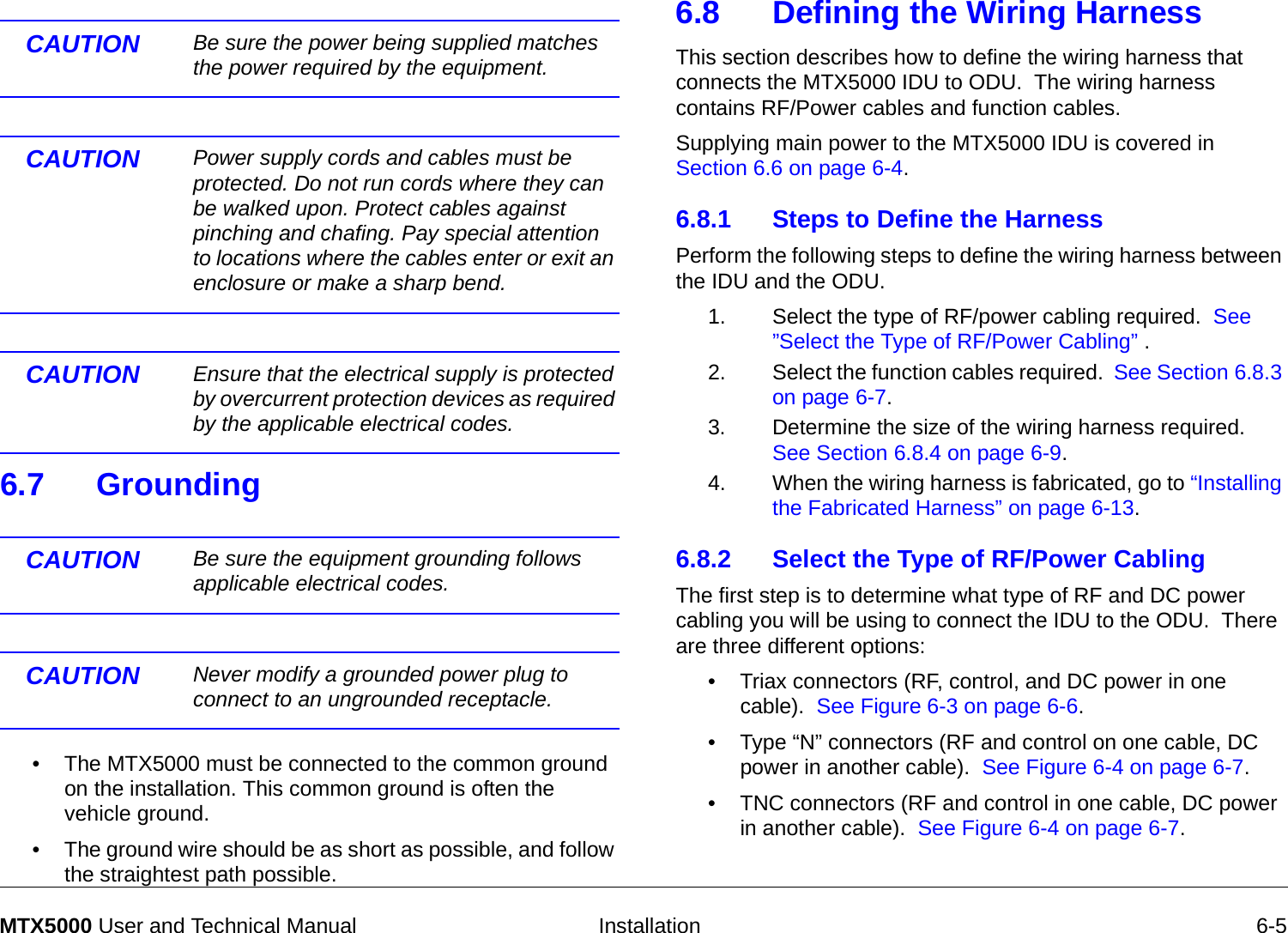
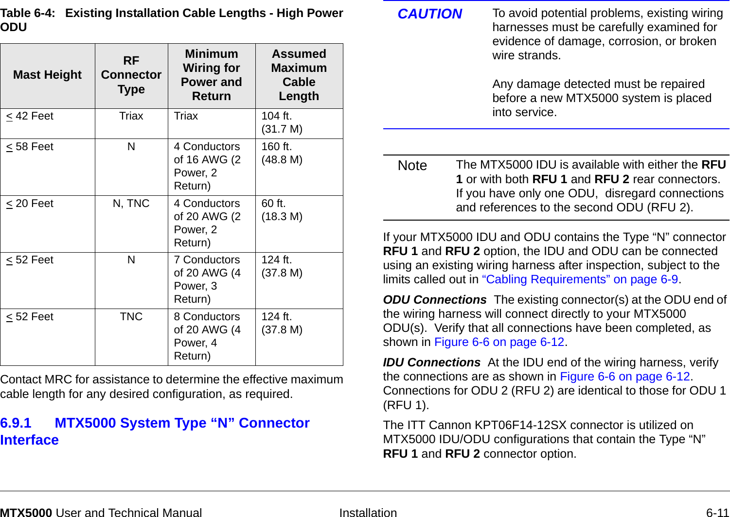
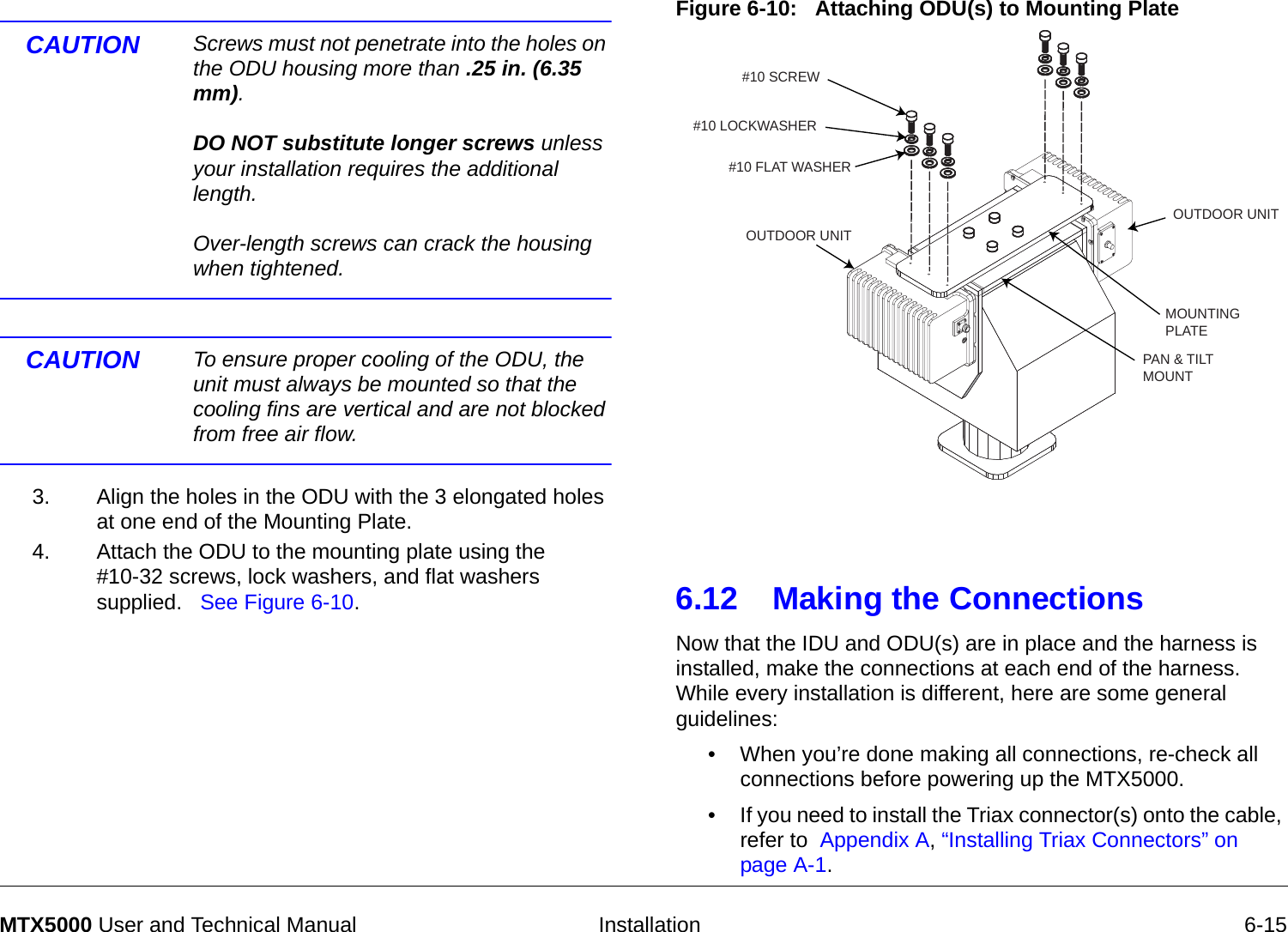
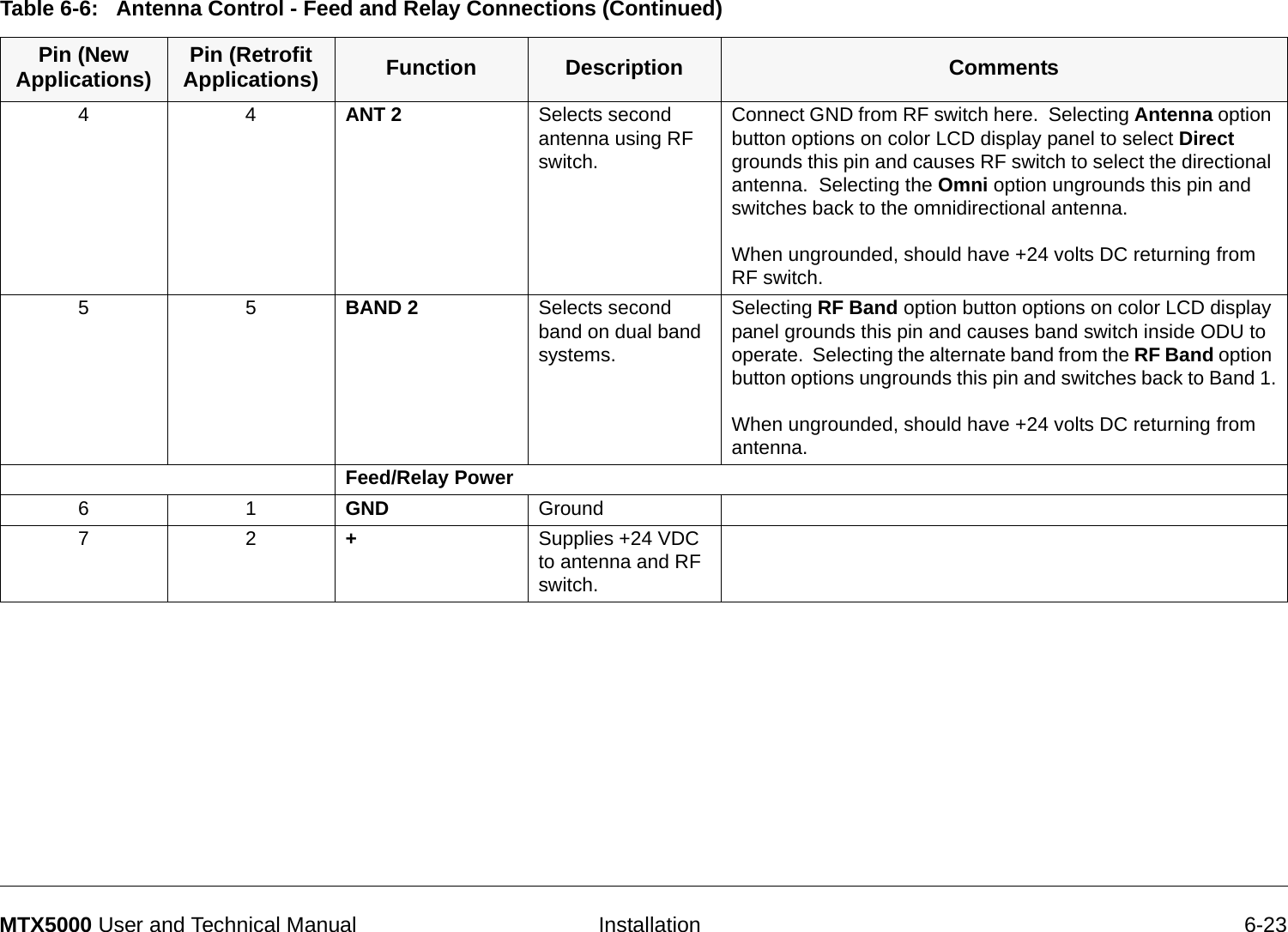
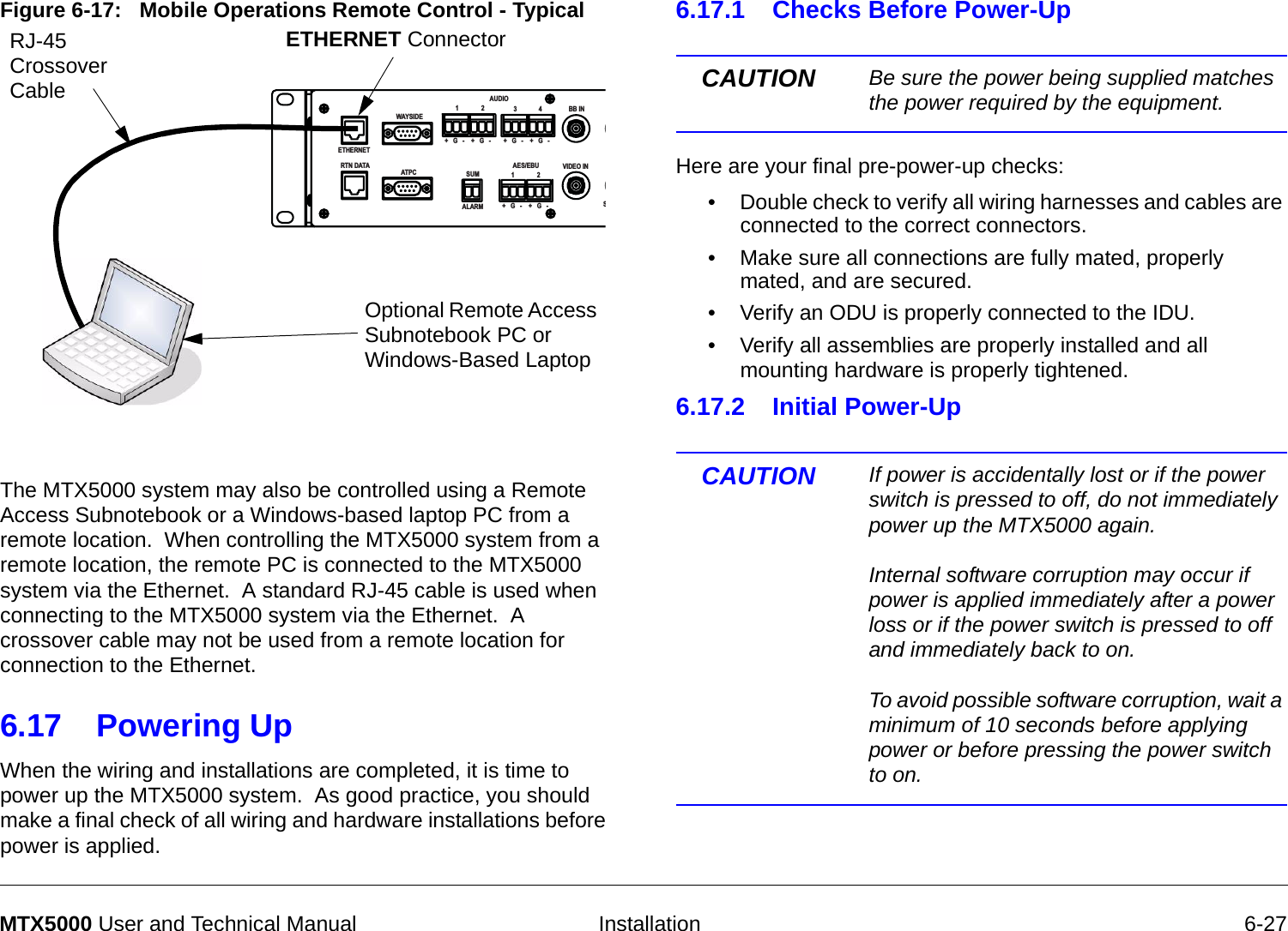
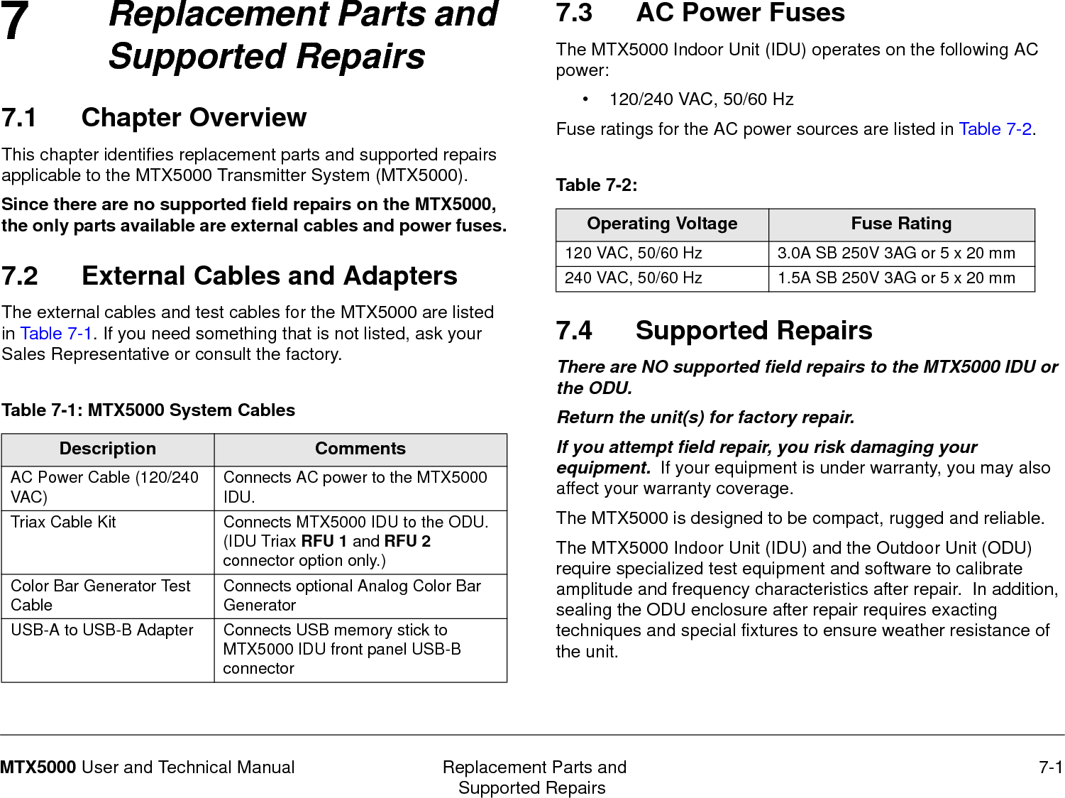
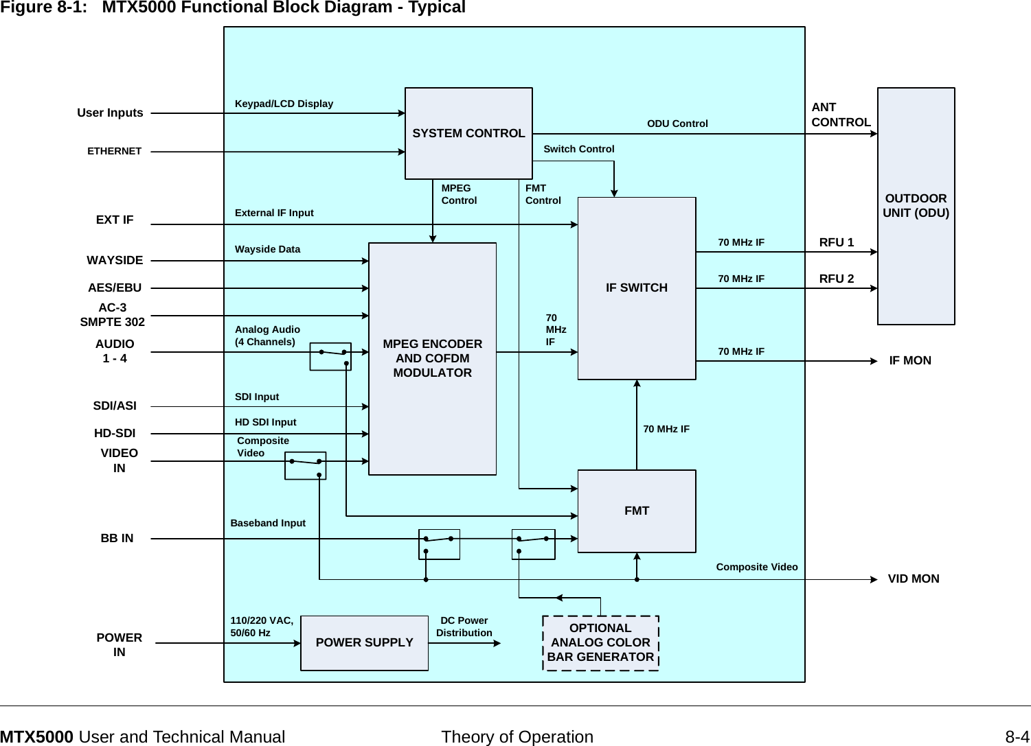
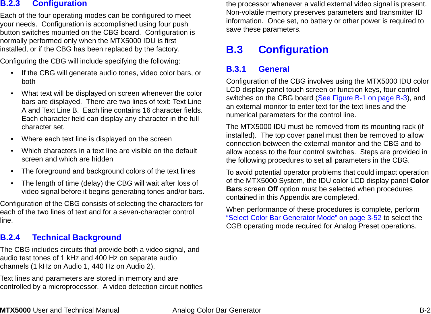
![Installation 6-9MTX5000 User and Technical Manual6.8.4 Determine the Size of Harness RequiredLength The length of your harness is set by the length of the mast when fully raised. Refer to Table 6-2 to locate typical dimensions, as shown in Figure 6-5. Note these are only typical dimensions. Your harness may be different. The formula used to determine theoretical end-to-end cable lengths (See Figure 6-5) is as follows:Overall Length = (DIM A - 5 ft.) x 2 + DIM B + DIM CFor example, with a mast height of 58 ft., minus 5 ft. inside the truck = 53 ft. x 2 = 106 ft. + 10 ft. + 20 ft. = 136 ft. Table 6-2: Harness DimensionsMast Height Overall Length Dim. A Dim. B Dim. C42’ [12.8 M] 104‘ [31.7 M] 74’ [22.5 M] 20‘ [6.0 M] 10‘ [3.0 M]48’ [14.6 M] 116’ [35.4 M] 86’ [26.2 M] 20‘ [6.0 M] 10‘ [3.0 M]58’ [17.7 M] 136’[41.5 M] 106‘ [32.3 M] 20‘ [6.0 M] 10‘ [3.0 M]Figure 6-5: Harness lengths6.9 Cabling RequirementsCAUTION To avoid potential problems, existing wiring harnesses must be carefully examined for evidence of damage, corrosion, or broken wire strands, and any damage detected must be repaired before a new MTX5000 system is placed into service.CAUTION Failure to provide sufficient current carrying capacity between the MTX5000 IDU and the ODU(s) may cause performance issues, including dropouts in transmission, and may cause damage to the equipment or to the installation.DIM ADIM AOverall LengthOverall LengthDIM CDIM CDIM BDIM BNycoil ConduitNycoil ConduitIDU EndIDU EndODU EndODU EndA = Length of Nycoil onlyB = Length of cables outside Nycoil on IDU endC = Length of cables outside Nycoil on RFU (RFU) end](https://usermanual.wiki/Microwave-Radio-Communications/ODU2ATXADH.Manual-Part-2/User-Guide-1220284-Page-103.png)
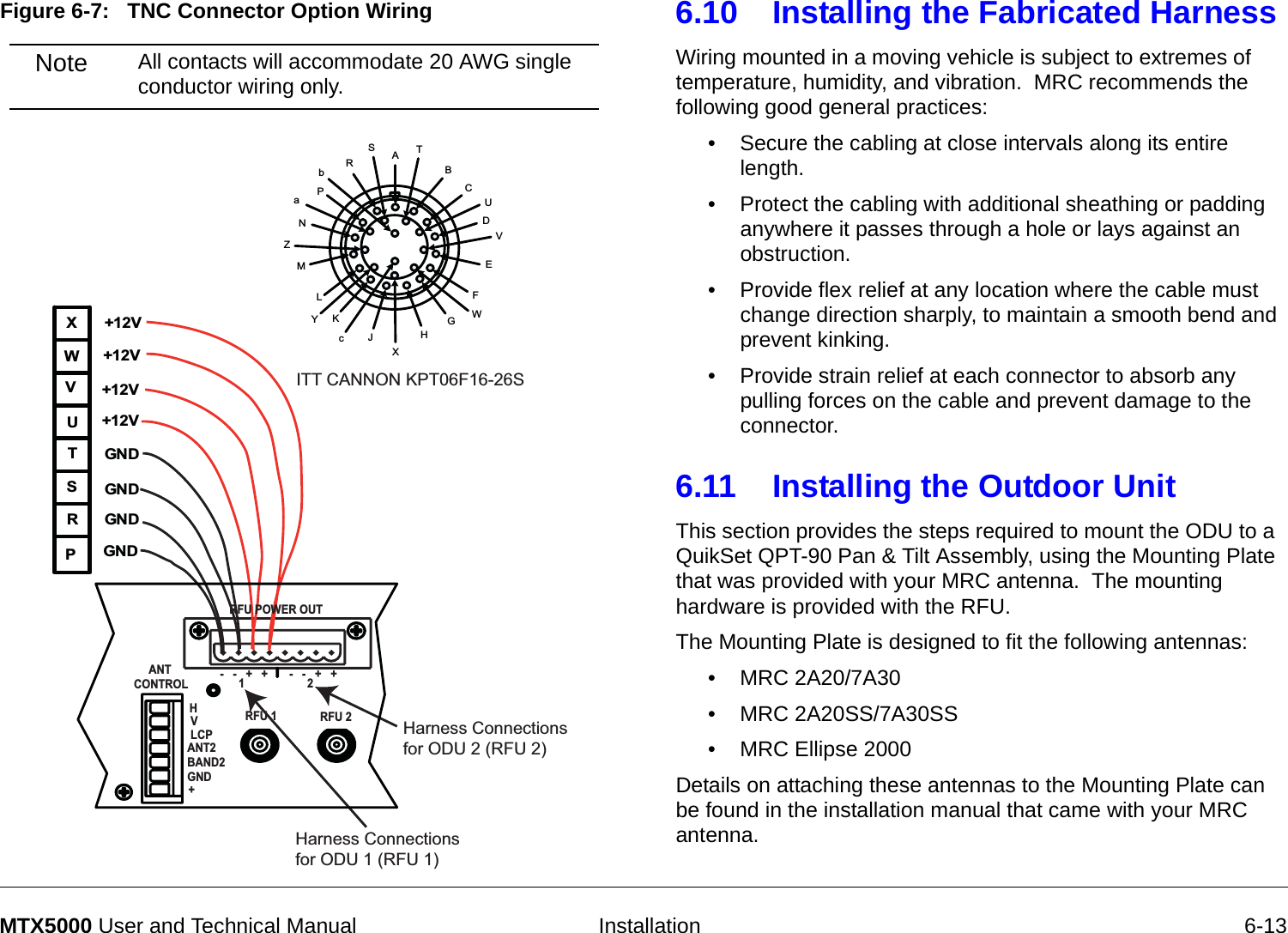
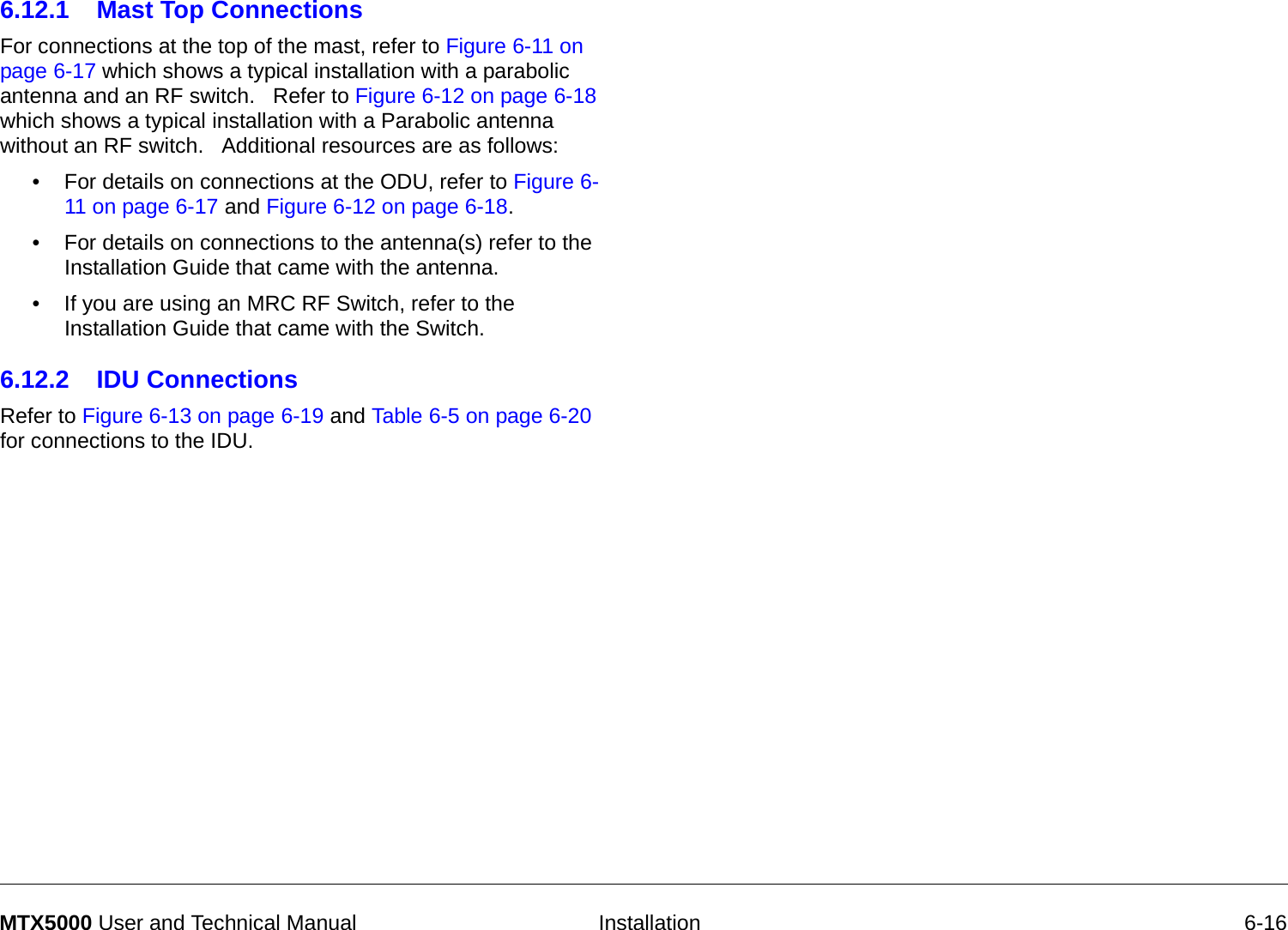
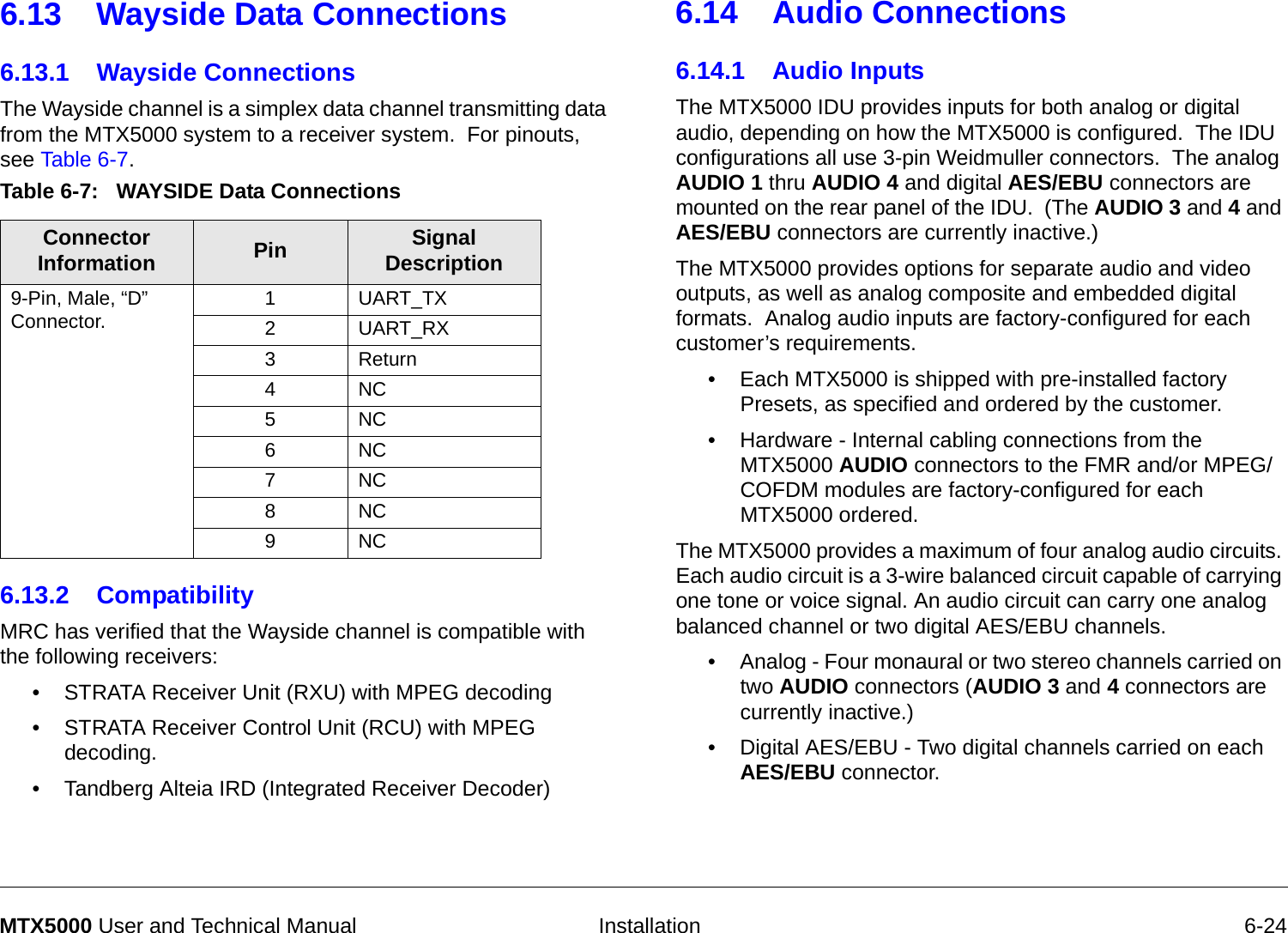
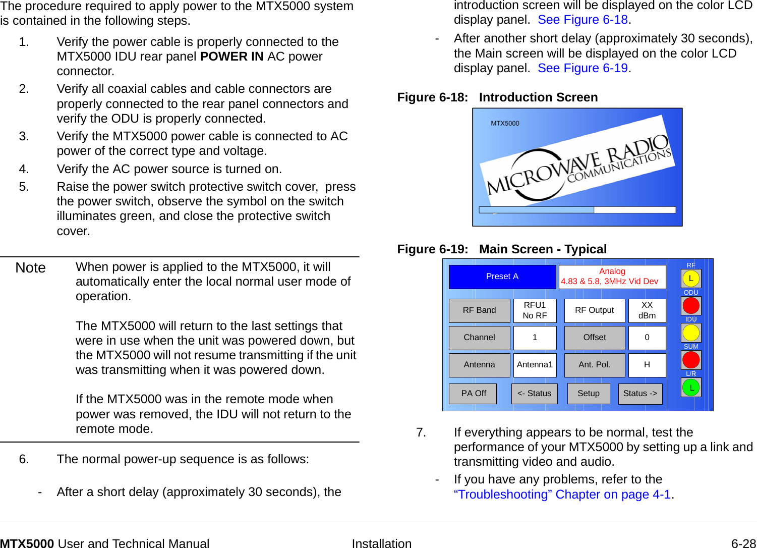

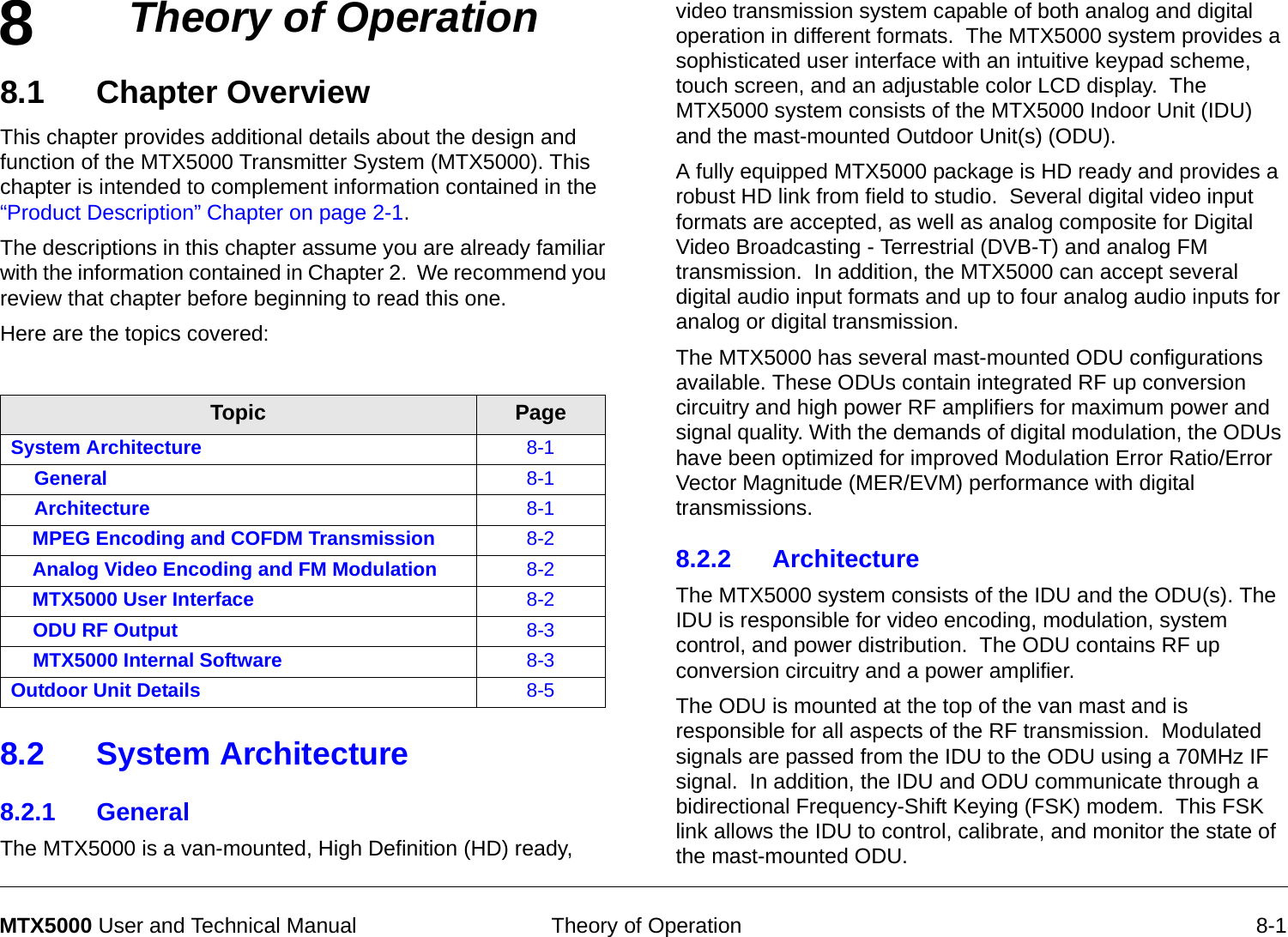
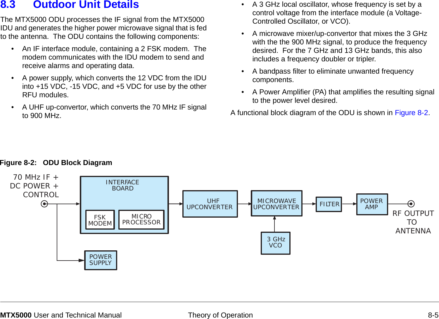
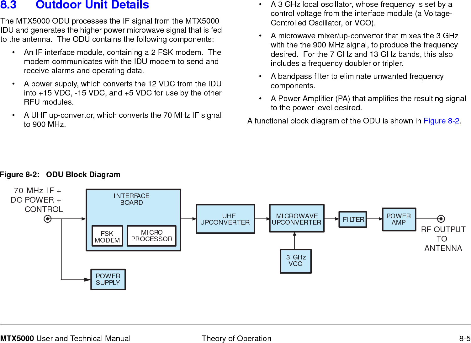
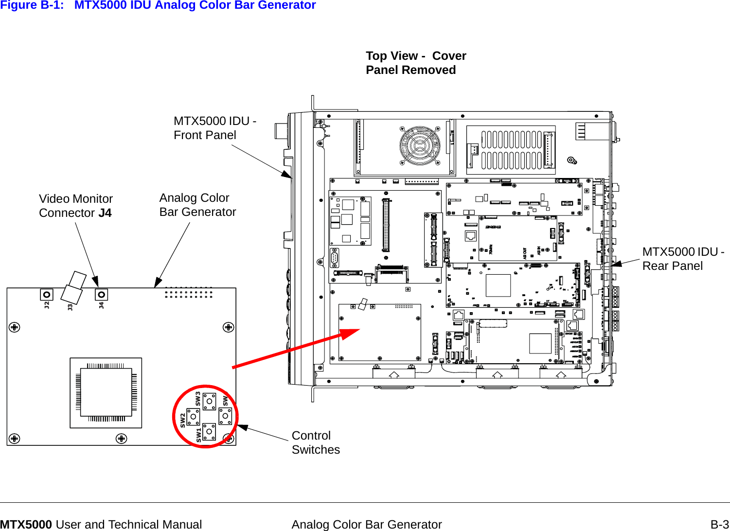
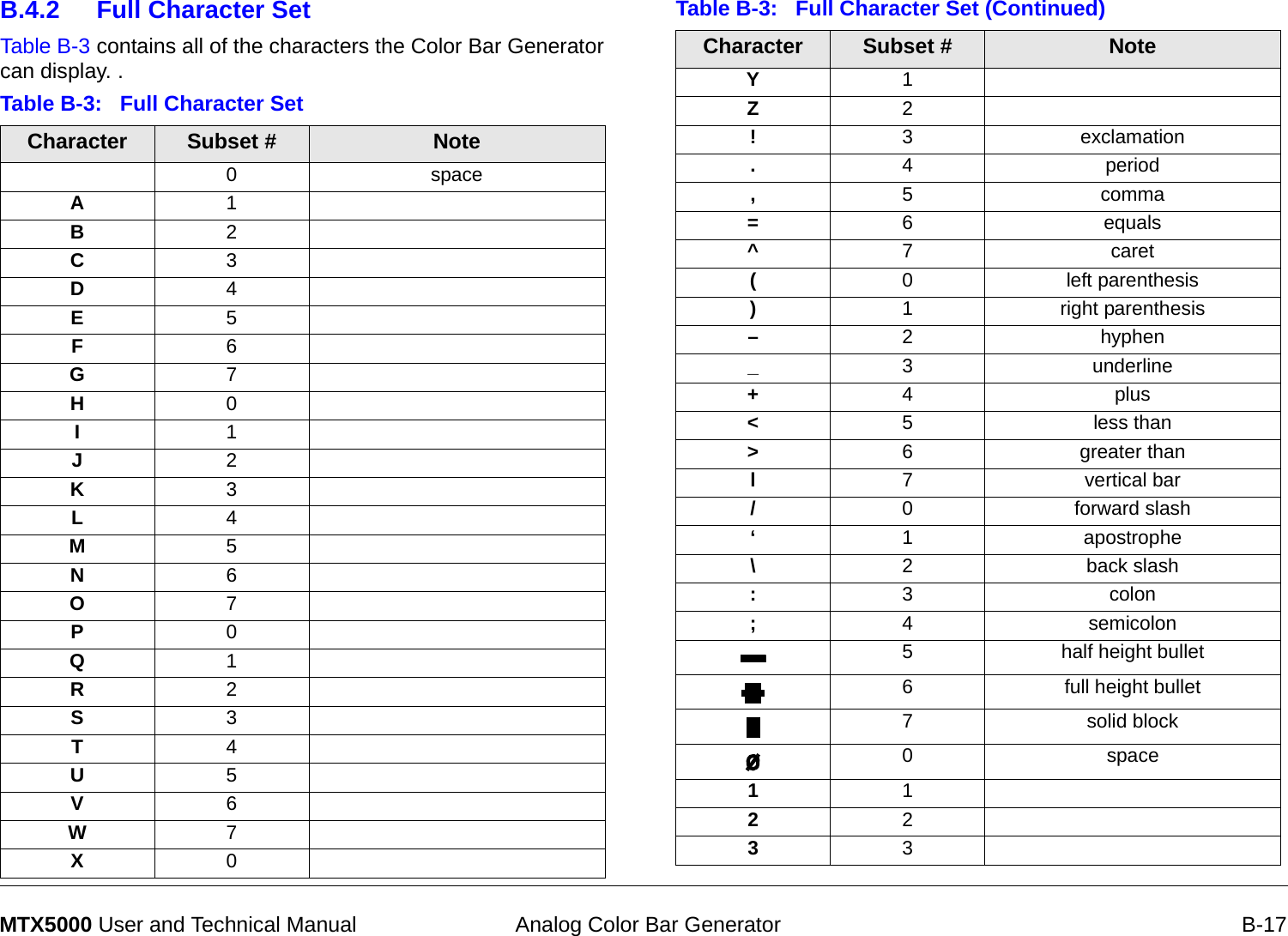
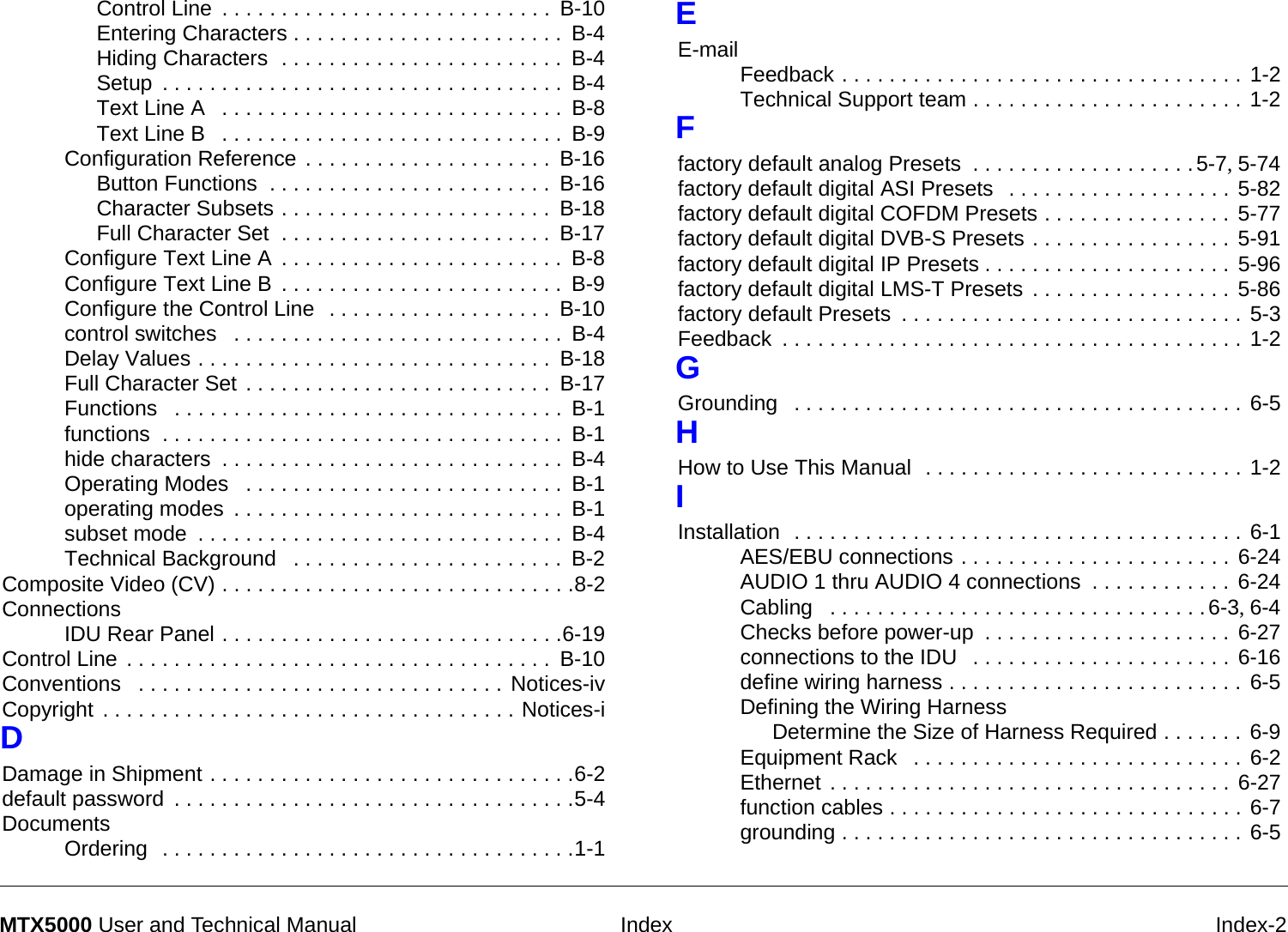
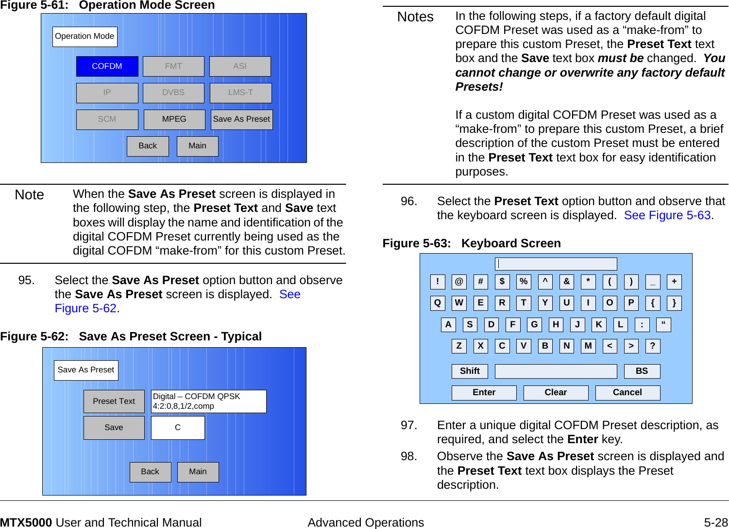
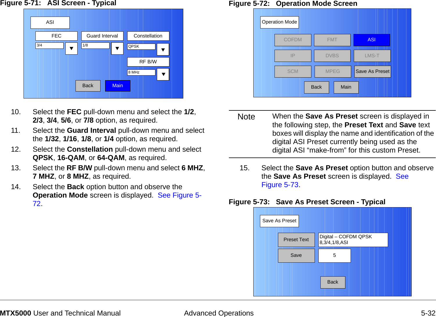
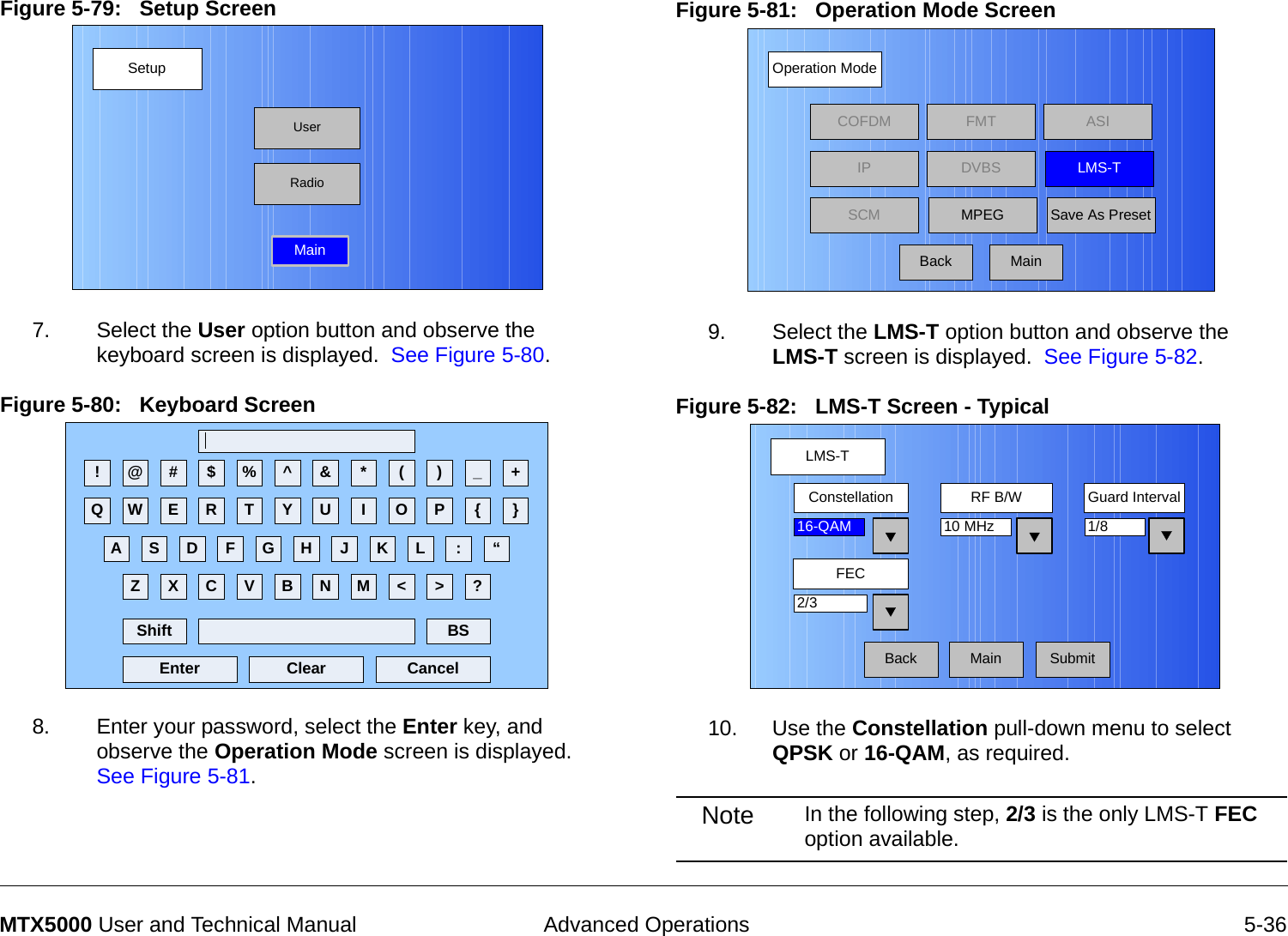
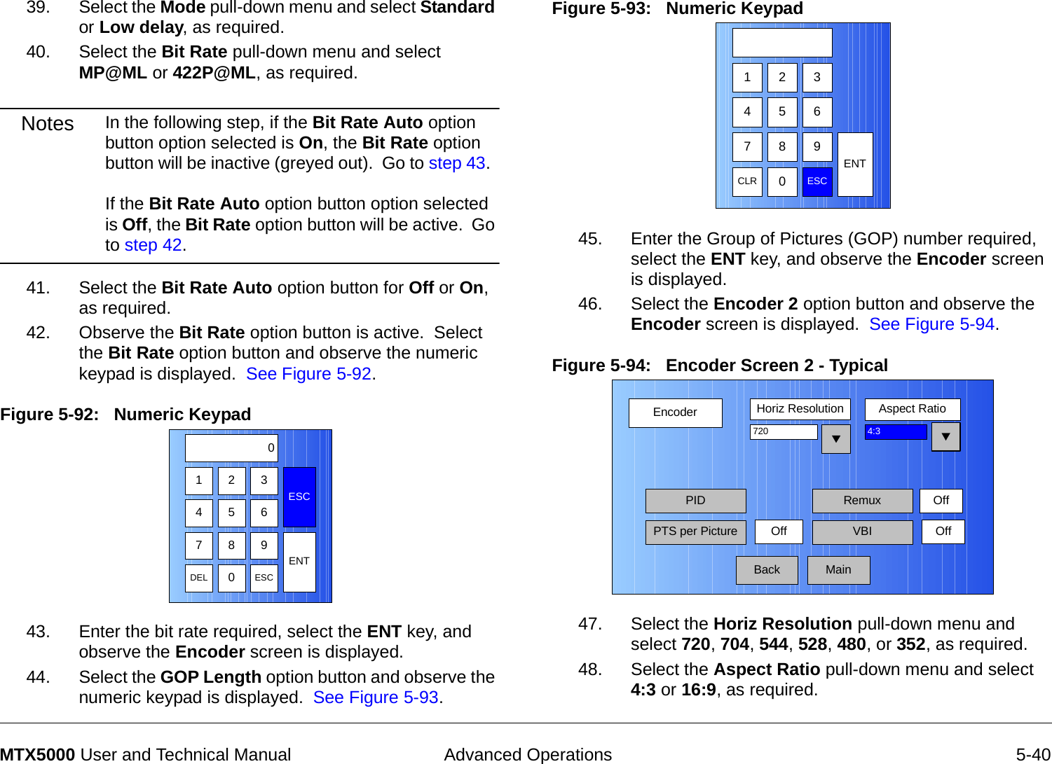
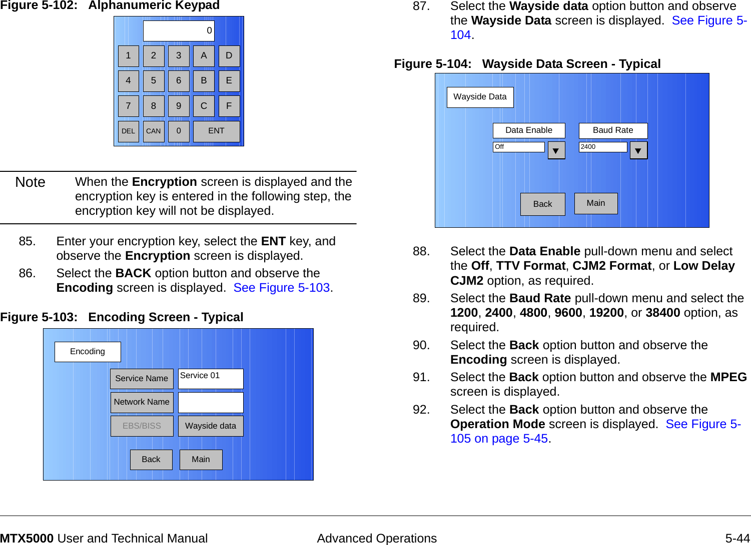
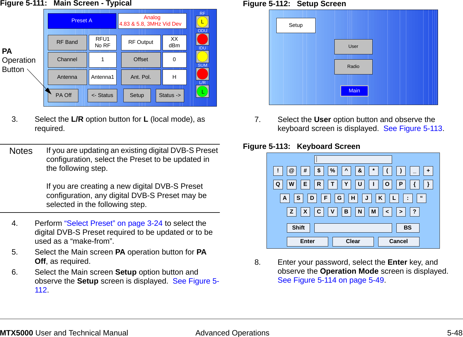
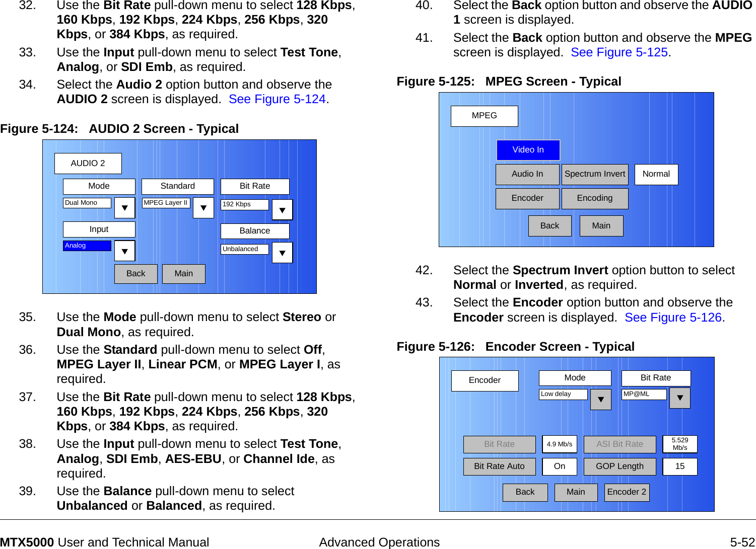
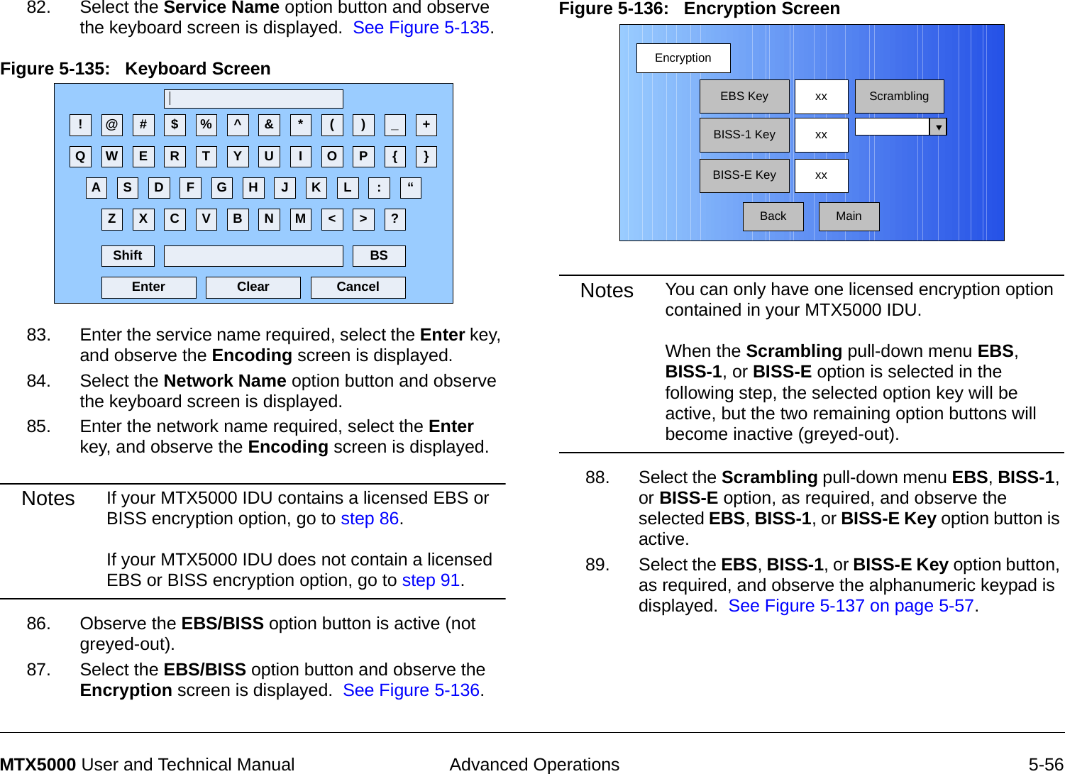
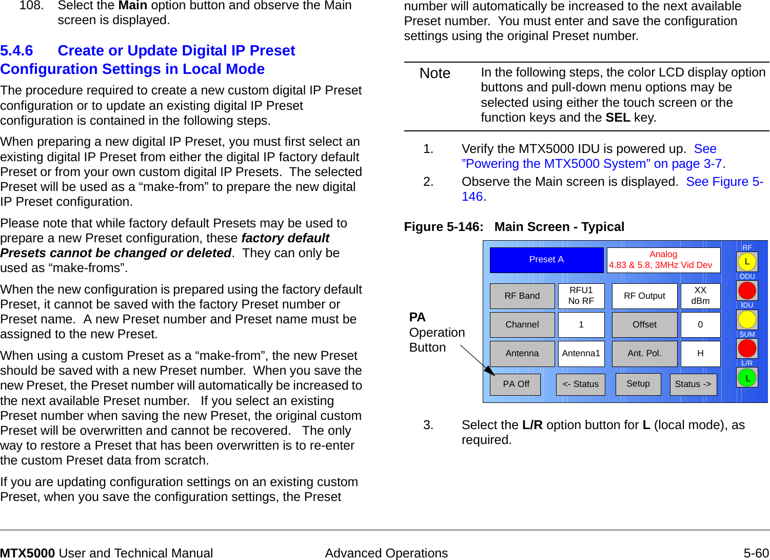
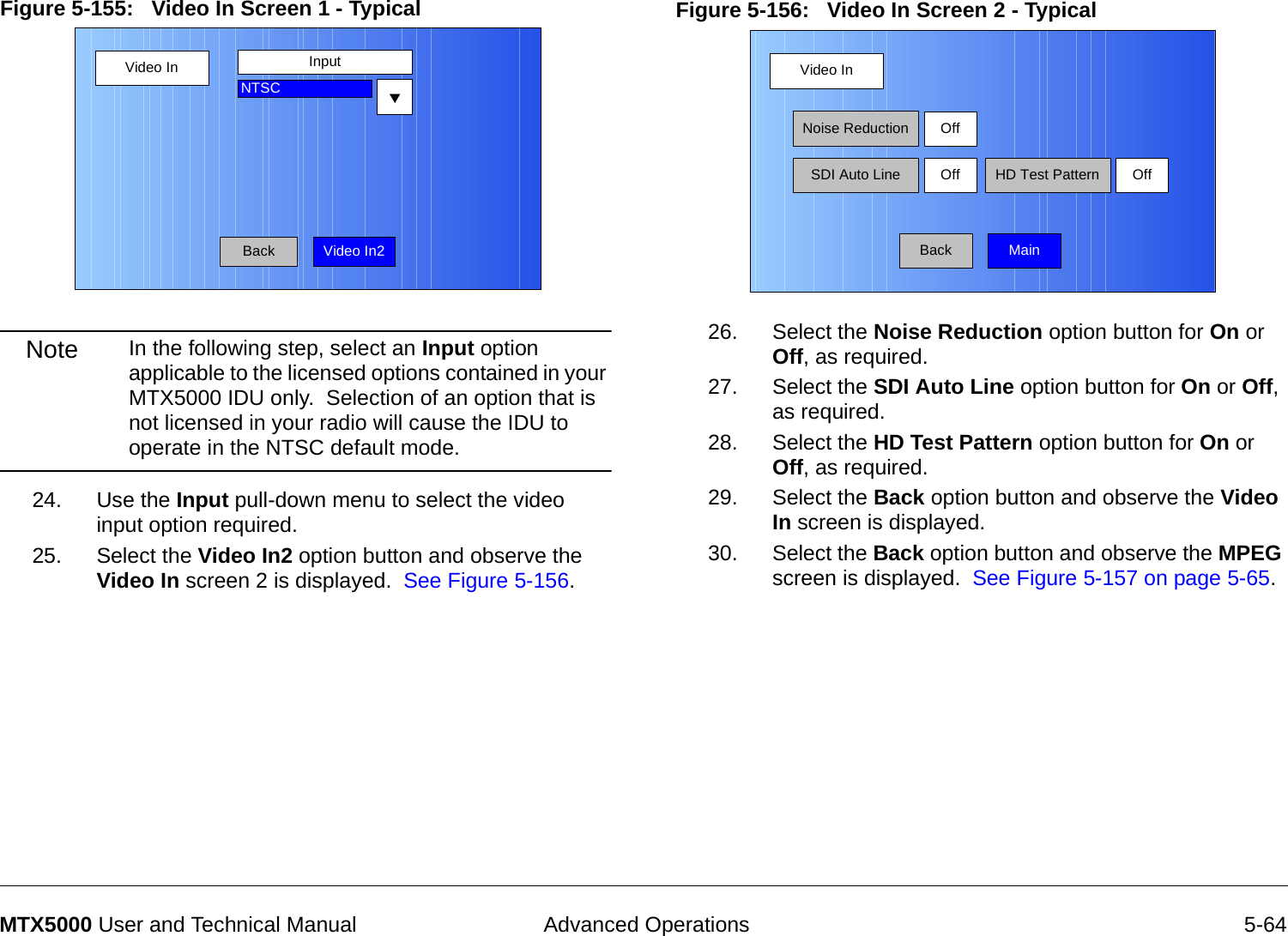
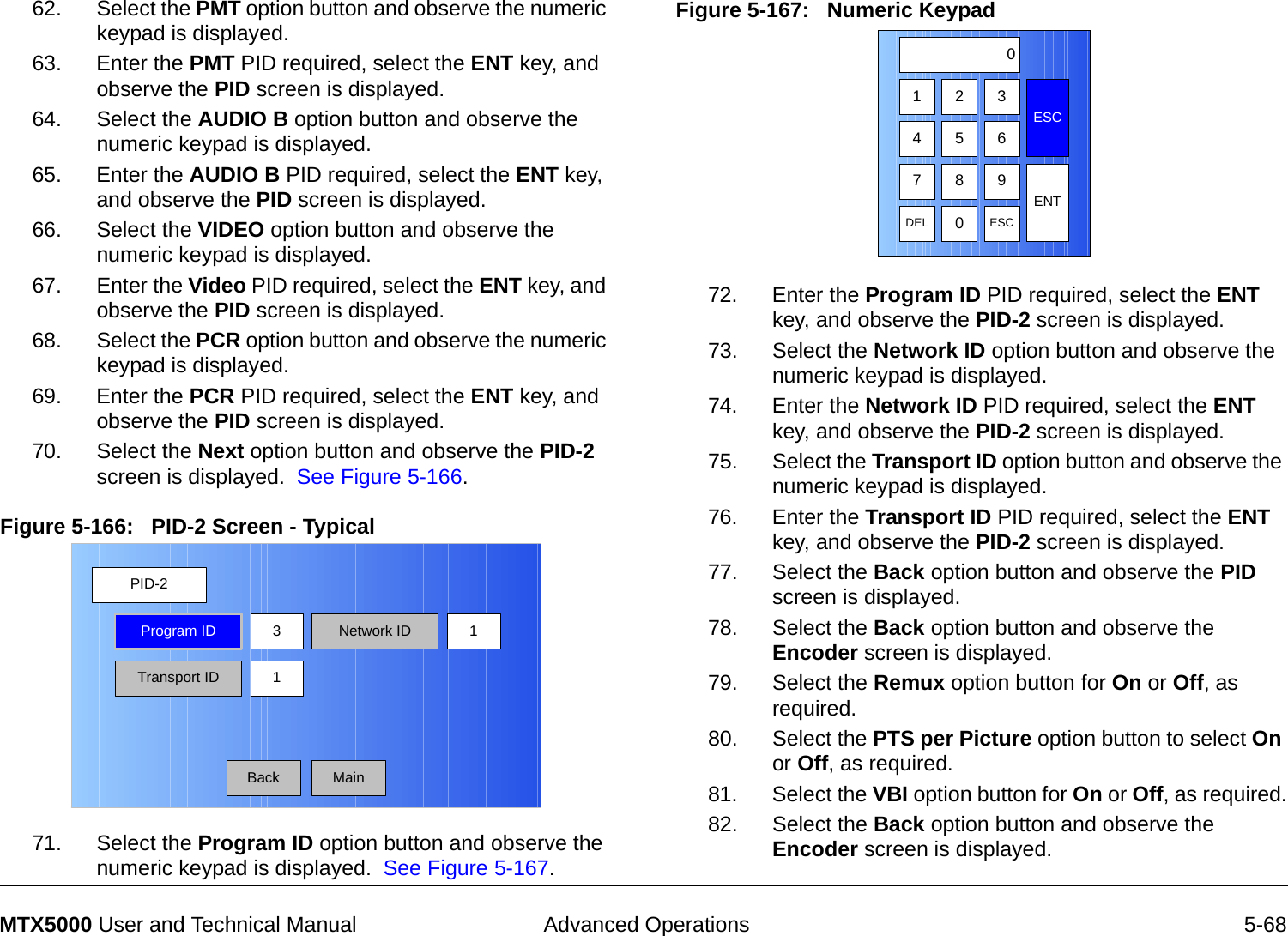
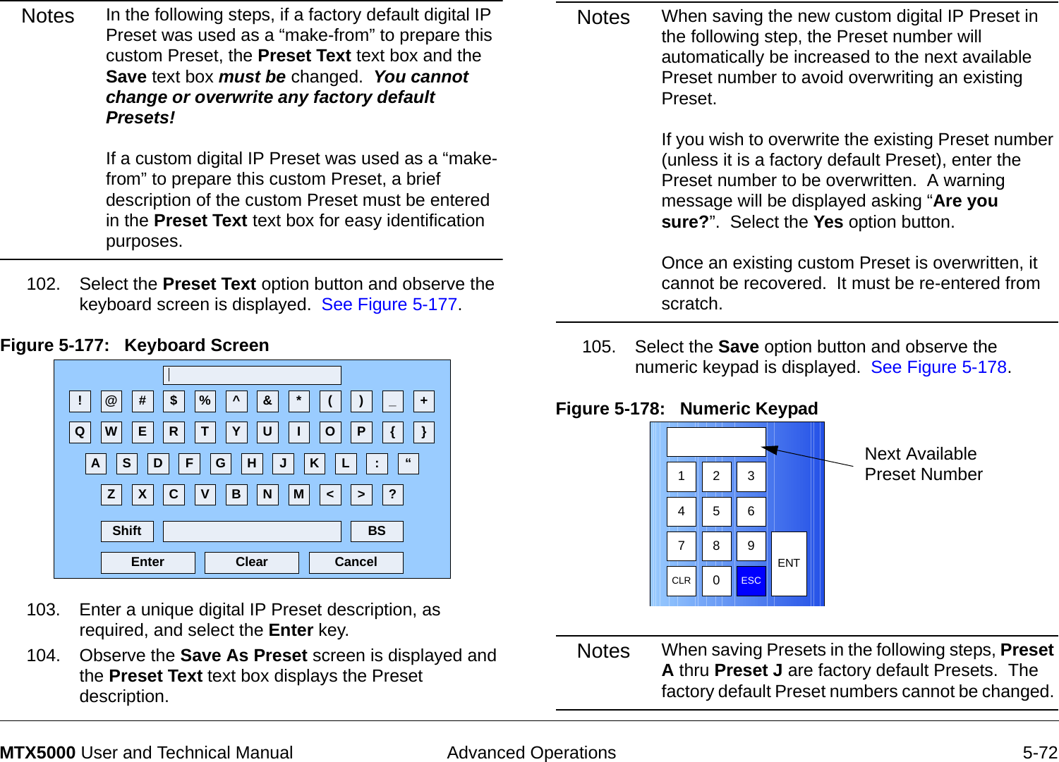
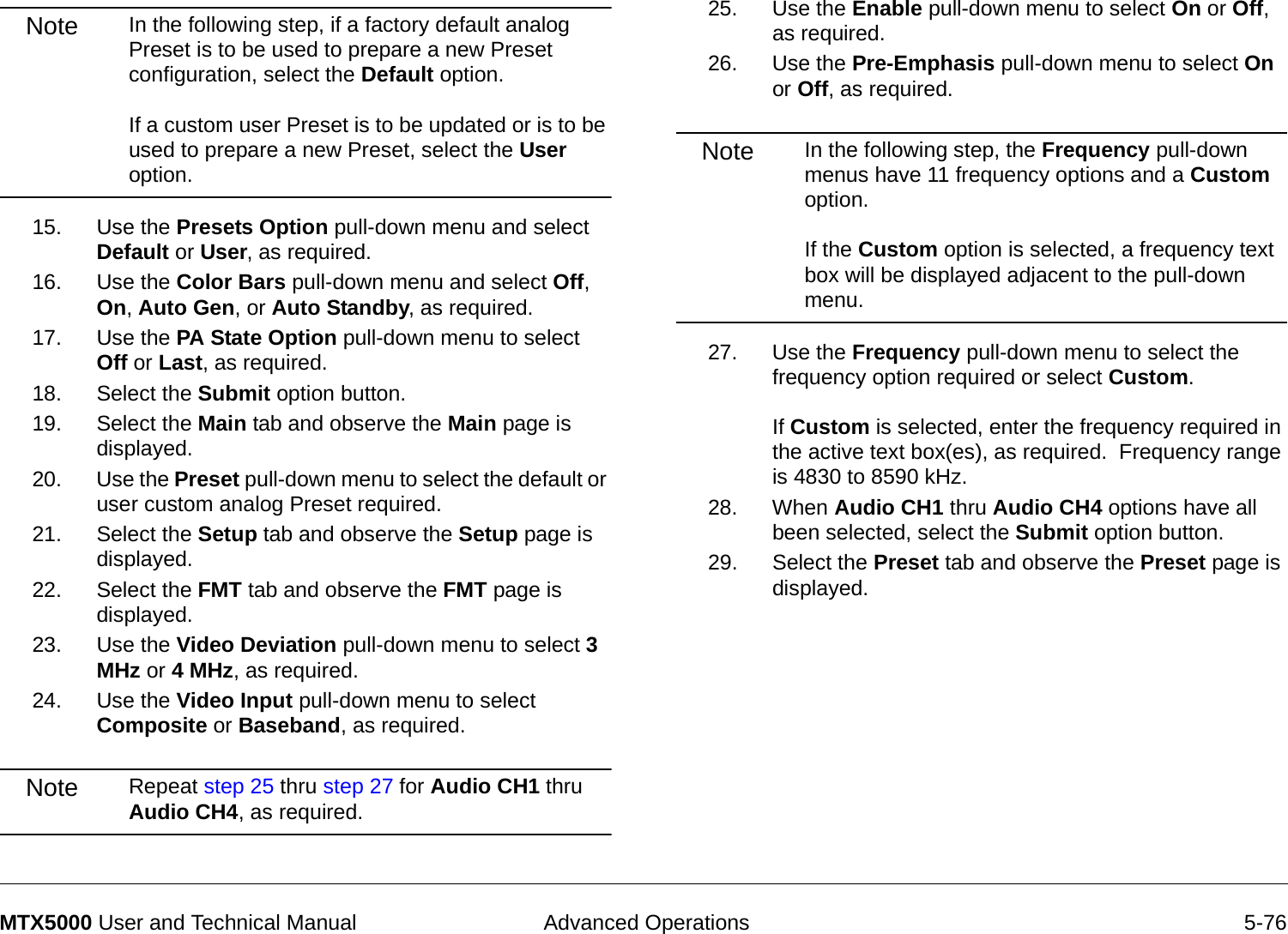
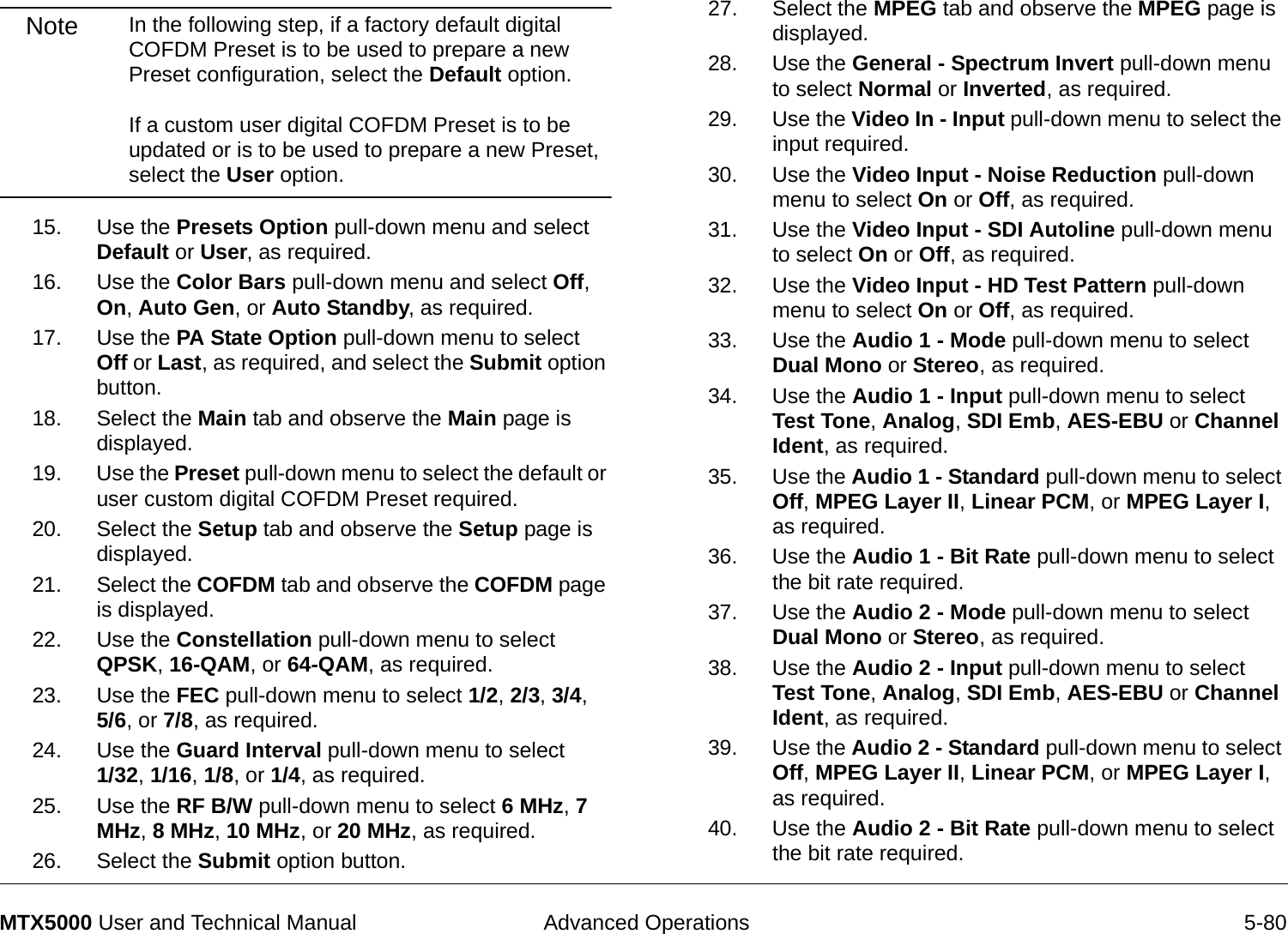
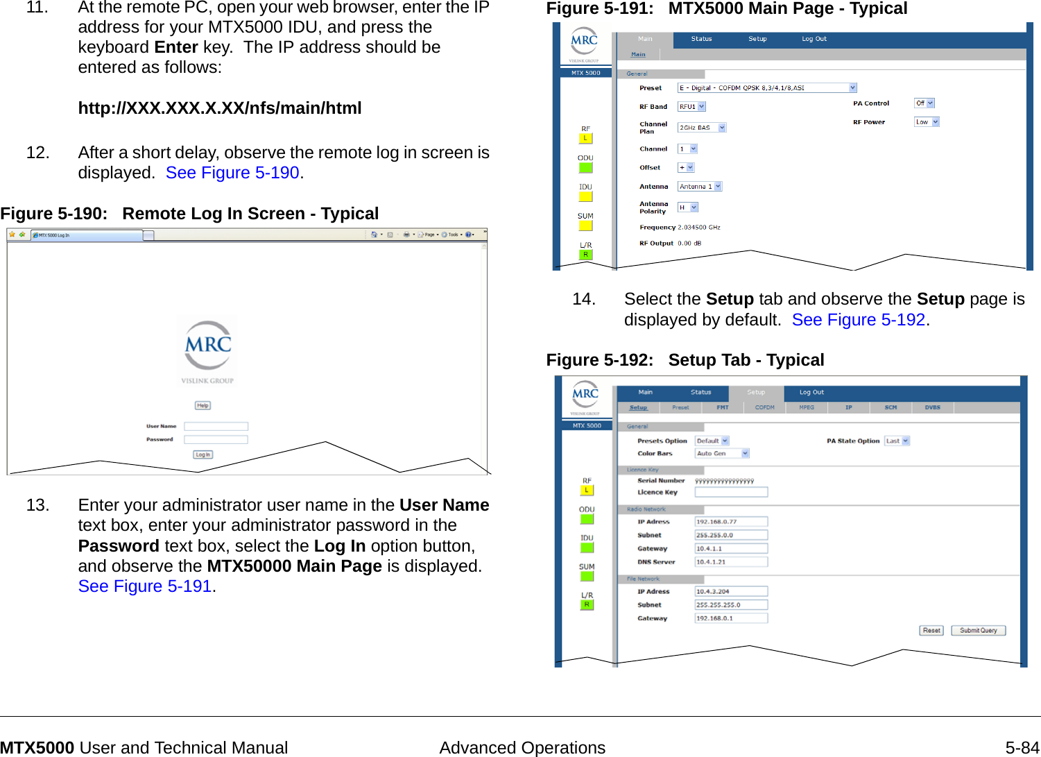
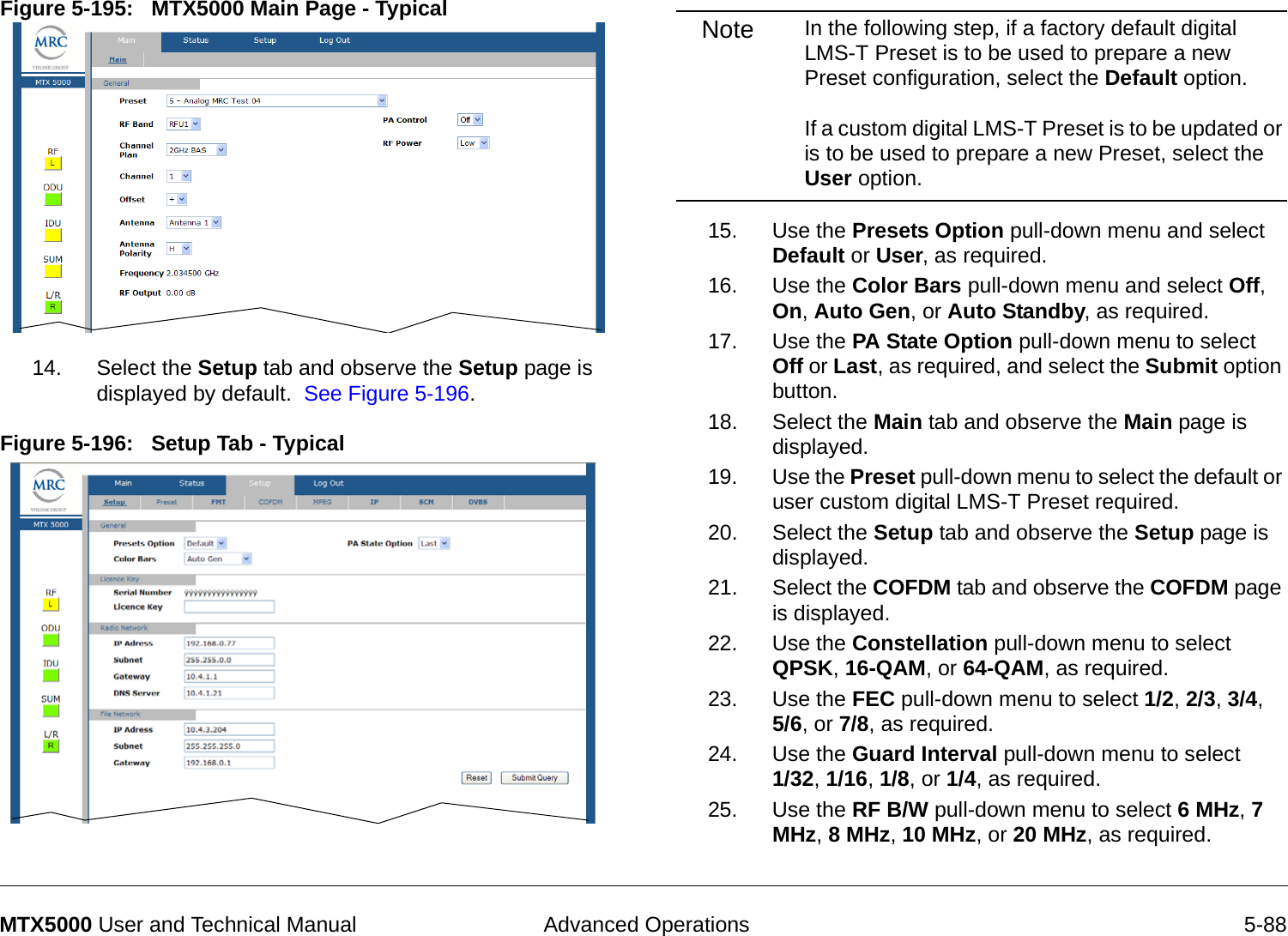
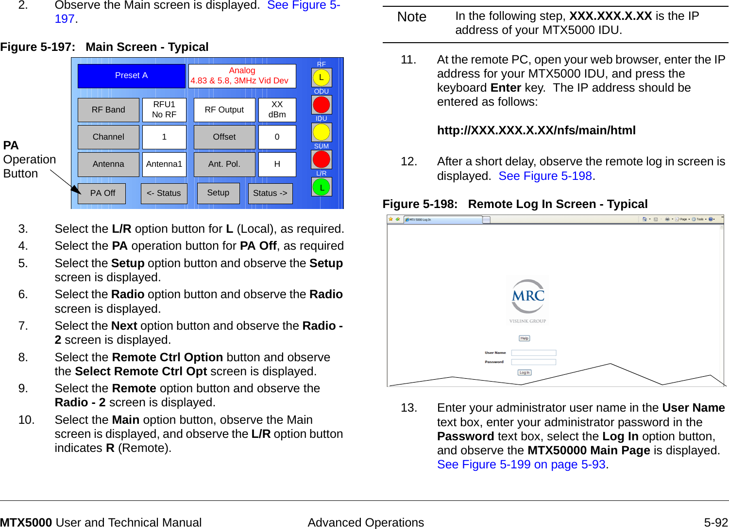
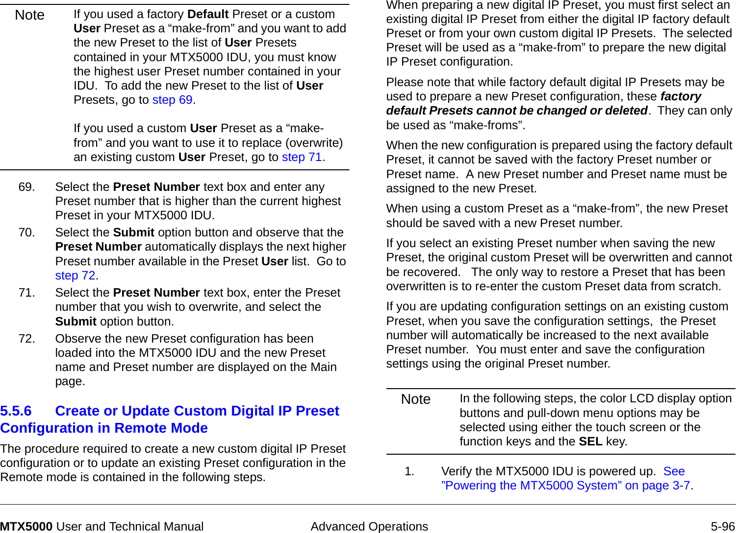
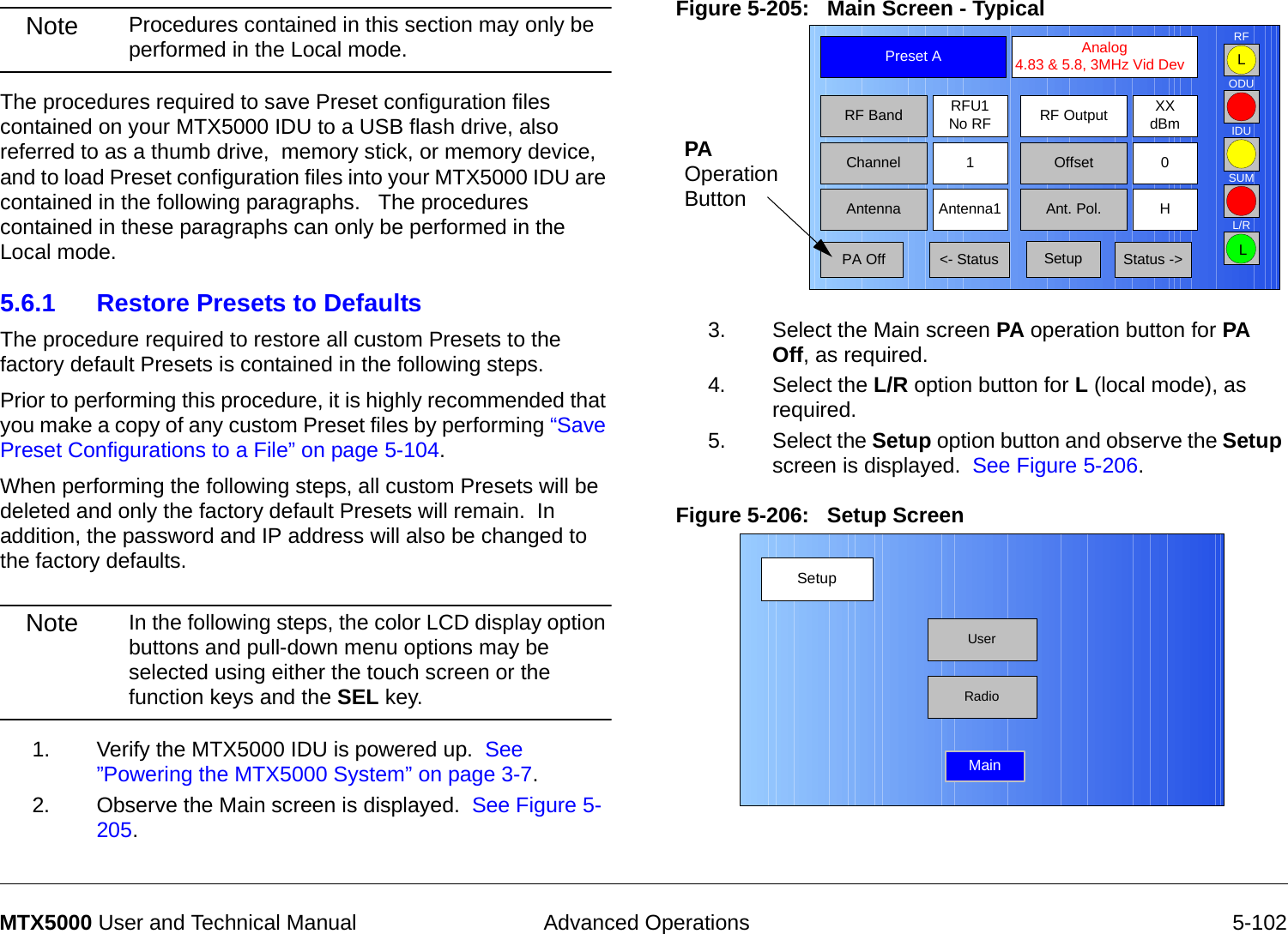
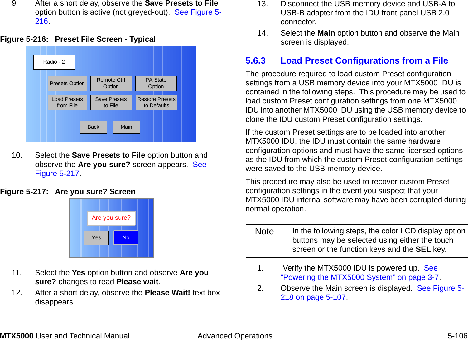
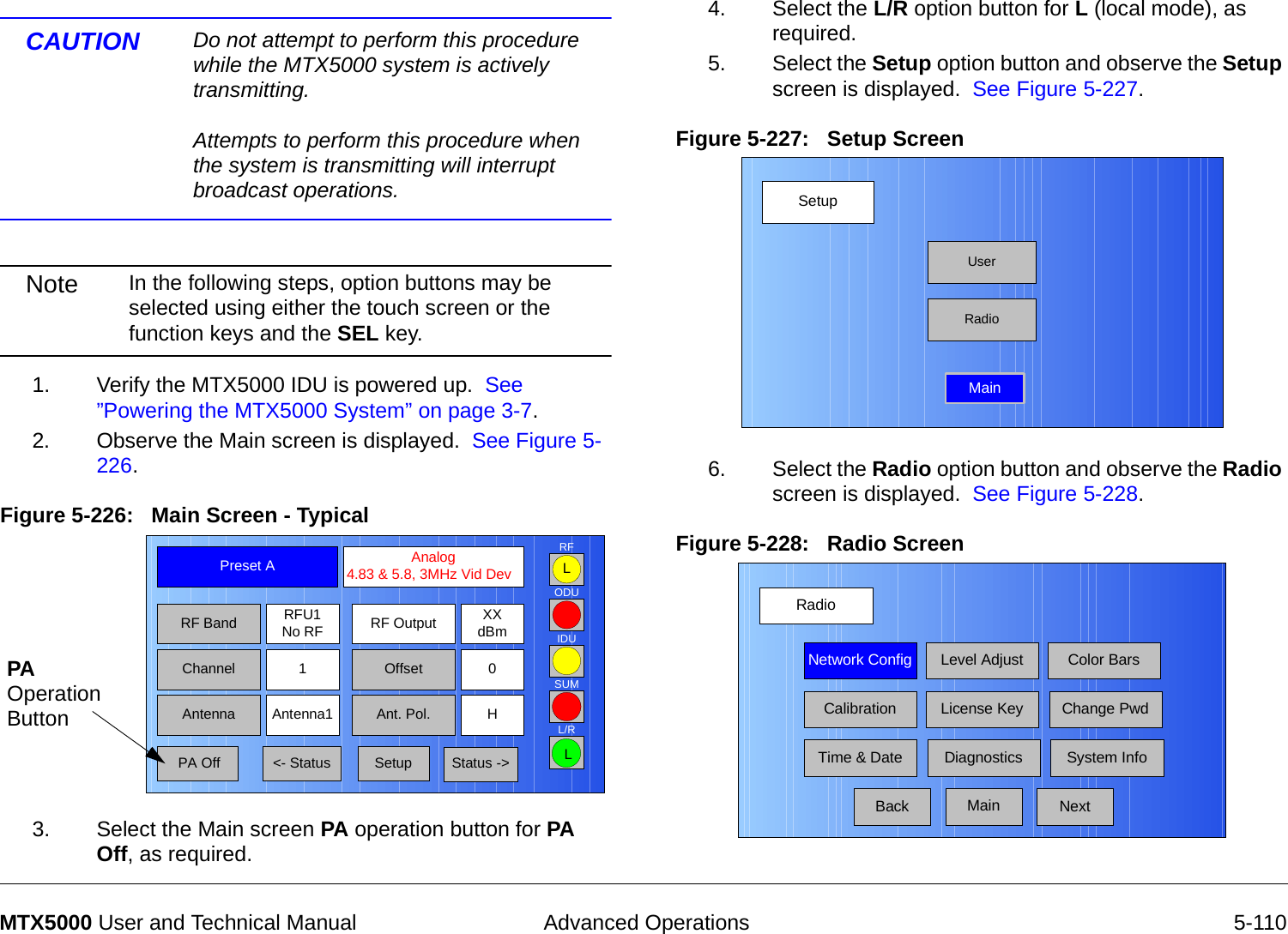
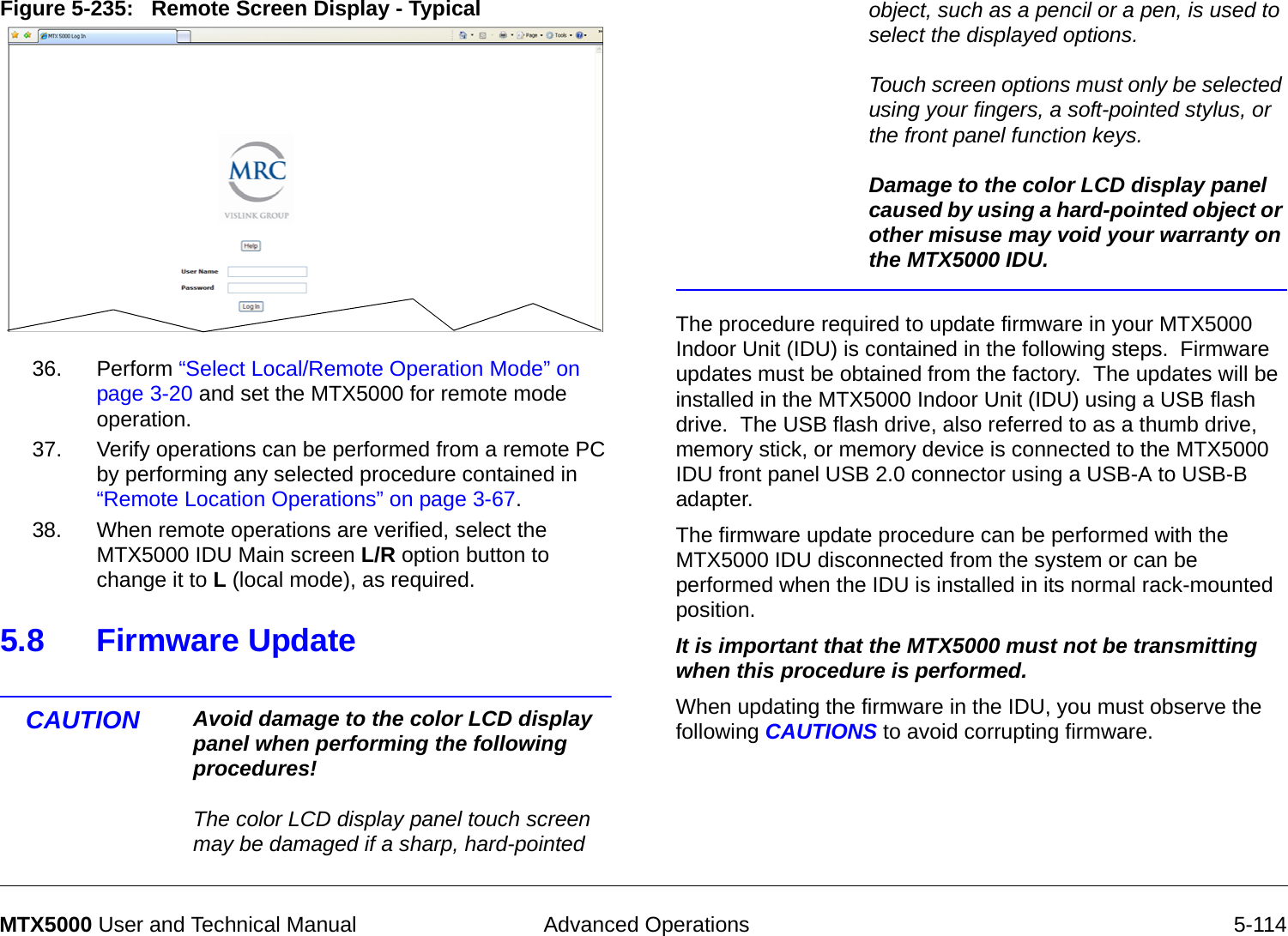
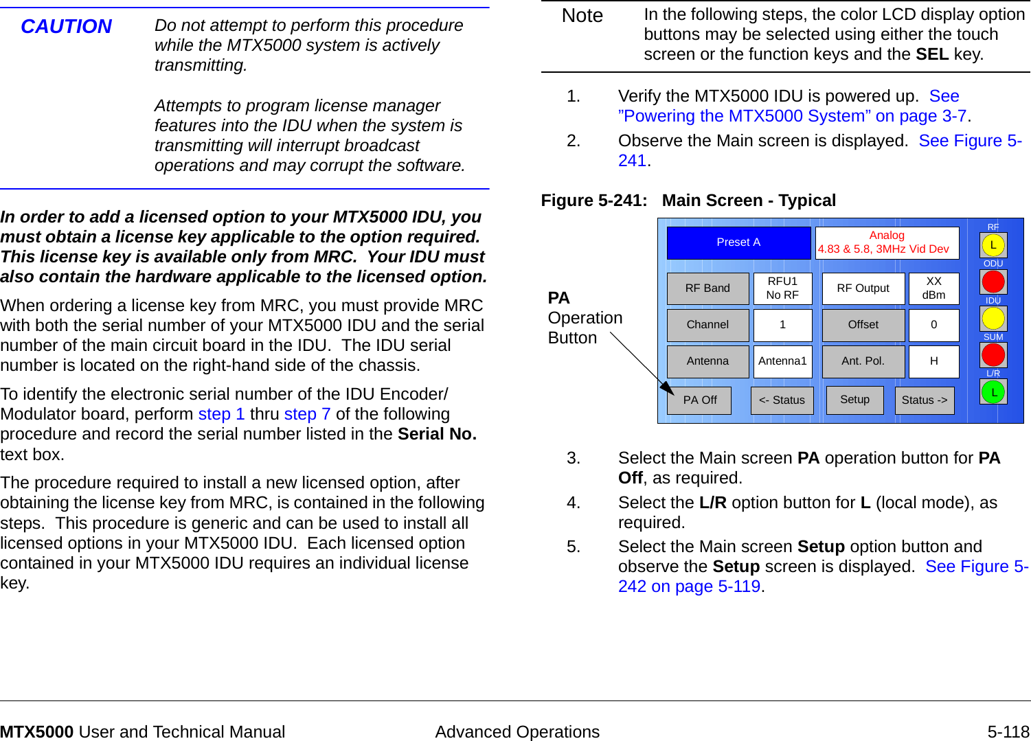
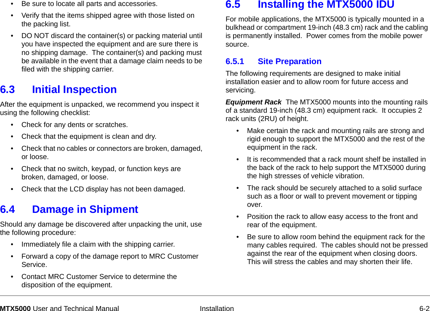
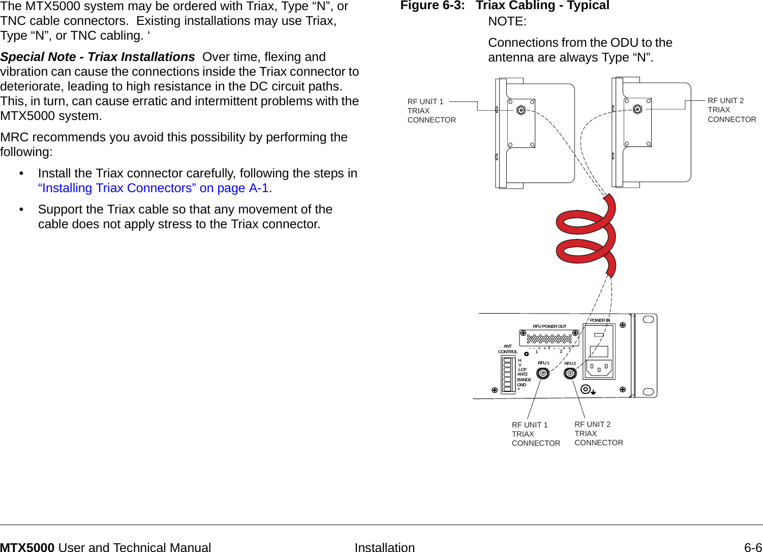
![Analog Color Bar Generator B-18MTX5000 User and Technical ManualB.4.3 Character SubsetsTable B-4 provides the character subsets the Color Bar Generator uses. Note: the subsets are also shown in Table B-3 on page B-17.Table B-4: Character Subsets 4455667780912T above a V#3number$4dollars%5percent&6ampersand (and)*7asteriskSubset # Character0(space), H, P, X, [(], /, , 81A, I, Q, Y, (, [‘], 1, 92B, J, R, Z,), \, 2, 3C, K, S,!, _, [:], 3, #4D, L, T, [.], _, [;], 4, $5E, M, U, [,], +, , 5,%Table B-3: Full Character Set (Continued)Character Subset # NoteB.4.4 Delay ValuesTable B-5 provides the delay in seconds corresponding to each value in Control Line fields 1 and 2. Note that the delay values repeat themselves so that a setting of 4,0 results in the same delay as a setting of 0,0 (1 second). 6F, N, V, =, <, , 6, &7G, O, W, ^, |, , 7, *Table B-5: Delay Values Field Position1FieldPosition2Delay in Seconds0 0 10 1 20 2 30 3 40 4 50 5 60 6 70 7 81 0 91 1 101 2 111 3 121 4 131 5 141 6 151 7 16](https://usermanual.wiki/Microwave-Radio-Communications/ODU2ATXADH.Manual-Part-2/User-Guide-1220284-Page-154.png)