Microwave Radio Communications ODU2ATXADH 2GHz MTX Radio User Manual MTX User and Tech
Microwave Radio Communications LLC 2GHz MTX Radio MTX User and Tech
Contents
- 1. Manual Part 1
- 2. Manual Part 2
Manual Part 2

Advanced Operations 5-27MTX5000 User and Technical Manual
Figure 5-58: Alphanumeric Keypad
Note When the Encryption screen is displayed in the
following step and the encryption key is entered,
the actual encryption key will not be displayed.
86. Enter your encryption key, select the ENT key, and
observe the Encryption screen is displayed.
87. Select the Back option button and observe the
Encoding screen is displayed. See Figure 5-59.
Figure 5-59: Encoding Screen - Typical
1 2 3
0
4
7
5 6
8 9
DEL CAN 0ENT
A D
B E
C F
Encoding
Back
Service Name
Network Name
EBS/BISS Wayside data
Service 01
Main
88. Select the Wayside data option button and observe
the Wayside Data screen is displayed. See Figure 5-
60.
Figure 5-60: Wayside Data Screen - Typical
89. Select the Data Enable pull-down menu and select
the Off, TTV Format, CJM2 Format, or Low Delay
CJM2 option, as required.
90. Select the Baud Rate pull-down menu and select the
1200, 2400, 4800, 9600, 19200, or 38400 option, as
required.
91. Select the Submit option button.
92. Select the Back option button and observe the
Encoding screen is displayed.
93. Select the Back option button and observe the MPEG
screen is displayed.
94. Select the Back option button and observe the
Operation Mode screen is displayed. See Figure 5-
61 on page 5-28.
Wayside Data
Back
Data Enable Baud Rate
Off 2400
Main
Advanced Operations 5-28MTX5000 User and Technical Manual
Figure 5-61: Operation Mode Screen
Note When the Save As Preset screen is displayed in
the following step, the Preset Text and Save text
boxes will display the name and identification of the
digital COFDM Preset currently being used as the
digital COFDM “make-from” for this custom Preset.
95. Select the Save As Preset option button and observe
the Save As Preset screen is displayed. See
Figure 5-62.
Figure 5-62: Save As Preset Screen - Typical
Operation Mode
Back
COFDM FMT ASI
IP
SCM
LMS-T
Save As Preset
DVBS
MPEG
Main
Save As Preset
Back
Preset Text Digital – COFDM QPSK
4:2:0,8,1/2,comp
Save C
Main
Notes In the following steps, if a factory default digital
COFDM Preset was used as a “make-from” to
prepare this custom Preset, the Preset Text text
box and the Save text box must be changed. You
cannot change or overwrite any factory default
Presets!
If a custom digital COFDM Preset was used as a
“make-from” to prepare this custom Preset, a brief
description of the custom Preset must be entered
in the Preset Text text box for easy identification
purposes.
96. Select the Preset Text option button and observe that
the keyboard screen is displayed. See Figure 5-63.
Figure 5-63: Keyboard Screen
97. Enter a unique digital COFDM Preset description, as
required, and select the Enter key.
98. Observe the Save As Preset screen is displayed and
the Preset Text text box displays the Preset
description.
! @ # $ % ^ & * ( ) _ +
Q W E R T Y U I O P { }
A S D F G H J K L :
Z X C V B N M < > ?
Shift BS
Clear CancelEnter
“

Advanced Operations 5-29MTX5000 User and Technical Manual
Notes When saving the new custom digital Preset in the
following step, the Preset number will automatically
be increased to the next available Preset number
to avoid overwriting an existing Preset.
If you wish to overwrite the existing Preset number
(unless it is a factory default Preset), enter the
Preset number to be overwritten. A warning
message will be displayed asking “Are you
sure?”. Select the Yes option button.
Once an existing custom Preset is overwritten, it
cannot be recovered. It must be re-entered from
scratch.
99. Select the Save option button and observe the
numeric keypad is displayed. See Figure 5-64.
Figure 5-64: Numeric Keypad - Typical
Notes When saving Presets in the following steps, Preset
A thru Preset J are factory default Presets. The
factory default Preset numbers cannot be changed.
1 2 3
4
7
5 6
8 9
CLR 0ESC
ENT
Next Available
Preset Number
Notes To change the default Preset number, perform step
100 and go to step 101.
To accept the next available Preset number, go to
step 101
100. Select the CLR key and enter the Preset number
required.
101. Select the ENT key and observe the Are you sure?
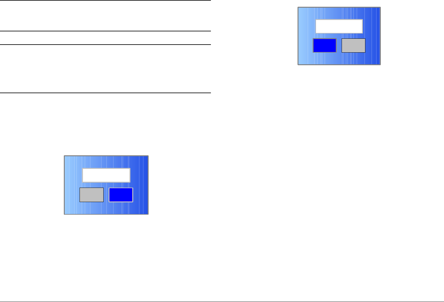
confirmation screen is displayed. See Figure 5-65.
Figure 5-65: Confirmation Screen
102. Select the YES option button and observe the Please
Wait! message box is displayed. See Figure 5-66.
Figure 5-66: Please Wait Message Box
103. After a short delay, observe the Save As Preset
screen is displayed.
No
Are you sure?
Yes
No
Please Wait!
Yes

Advanced Operations 5-30MTX5000 User and Technical Manual
104. Select the Main option button and observe the Main
screen is displayed.
5.4.3 Create or Update Digital ASI Preset
Configuration Settings in Local Mode
The procedure required to create a new custom digital ASI
Preset configuration or to update an existing digital ASI Preset
configuration is contained in the following steps.
When preparing a new digital ASI Preset, you must first select an
existing digital ASI Preset from either the ASI factory default
Preset or from your own custom digital ASI Presets. The
selected digital ASI Preset will be used as a “make-from” to
prepare the new digital ASI Preset configuration.
Please note that while the ASI factory default Preset may be
used to prepare a new Preset configuration, the factory default
Preset cannot be changed or deleted. It can only be used as
a “make-from”.
When the new configuration is prepared using the factory default
Preset, it cannot be saved with the factory Preset number or
Preset name. A new Preset number and Preset name must be
assigned to the new Preset.
When using a custom Preset as a “make-from”, the new Preset
should be saved with a new Preset number. When you save the
new Preset, the Preset number will automatically be increased to
the next available Preset number. If you select an existing
Preset number when saving the new Preset, the original custom
Preset will be overwritten and cannot be recovered. The only
way to restore a Preset that has been overwritten is to re-enter
the custom Preset data from scratch.
If you are updating configuration settings on an existing custom
Preset, when you save the configuration settings, the Preset
number will automatically be increased to the next available
Preset number. You must enter and save the configuration
settings using the original Preset number.
Note In the following steps, the color LCD display option
buttons and pull-down menu options may be
selected using either the touch screen or the
function keys and the SEL key.
1. Verify the MTX5000 IDU is powered up. See
”Powering the MTX5000 System” on page 3-7.
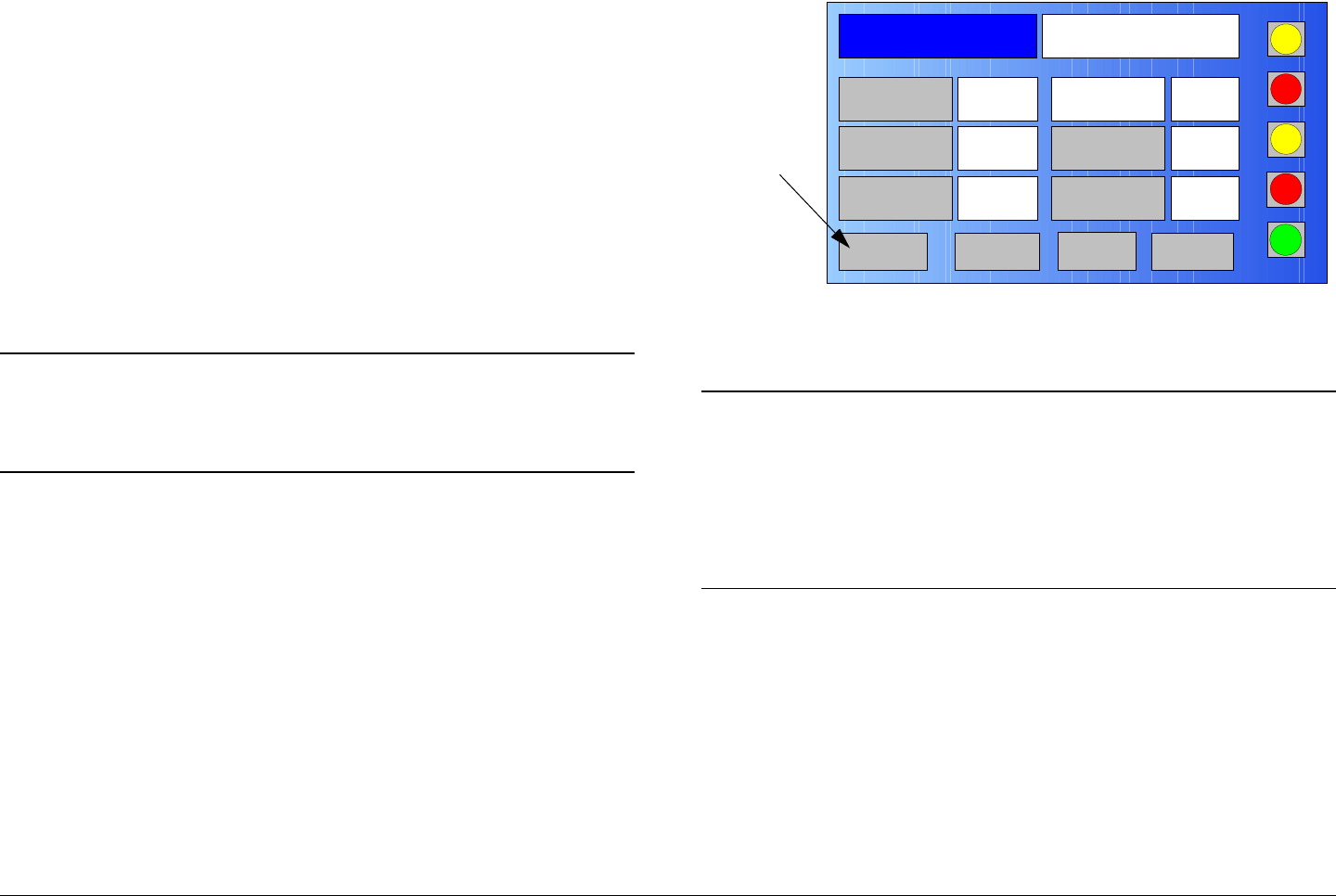
2. Observe the Main screen is displayed. See Figure 5-
67.
Figure 5-67: Main Screen - Typical
3. Select the L/R option button for L (local mode), as
required.
Channel 1 0Offset
Antenna Ant. Pol.Antenna1 H
RFU1
No RF
RF Band
Preset A Analog
4.83 & 5.8, 3MHz Vid Dev
RF Output XX
dBm
<- Status Setup Status ->
PA Off
SUM
ODU
IDU
RF
L/R
L
L
PA
Operation
Button
Advanced Operations 5-31MTX5000 User and Technical Manual
Notes If you are updating an existing digital ASI Preset
configuration, select the Preset to be updated in
the following step.
If you are creating a new digital ASI Preset
configuration, any digital ASI Preset may be
selected in the following step.
4. Perform “Select Preset” on page 3-24 to select the
digital ASI Preset required to be updated or to be used
as a “make-from”.
5. Select the Main screen PA operation button for PA
Off, as required.
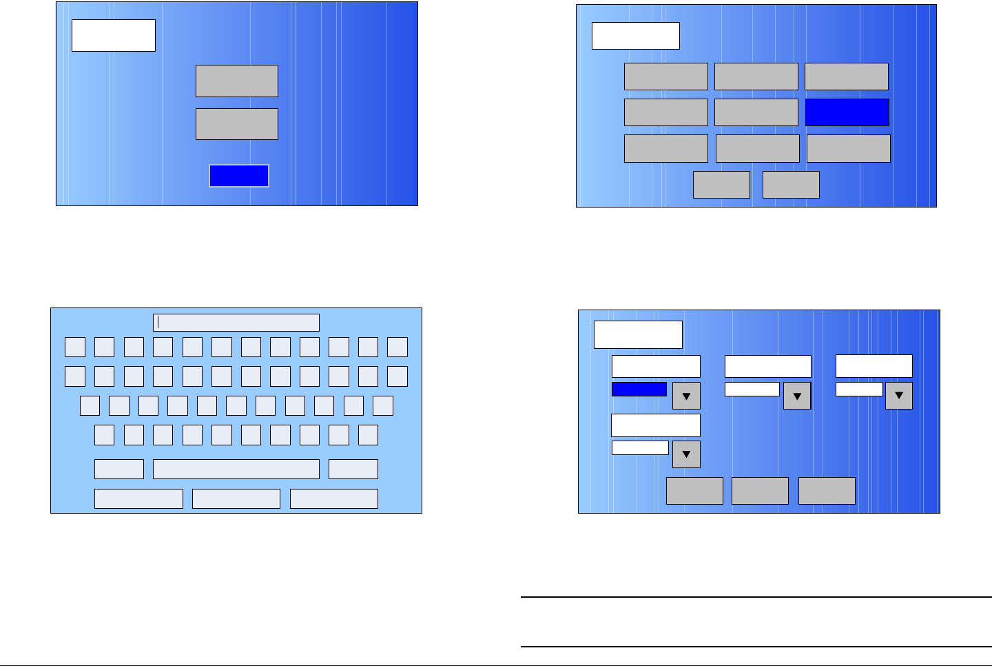
6. Select the Main screen Setup option button and
observe the Setup screen is displayed. See Figure 5-
68.
Figure 5-68: Setup Screen
7. Select the User option button and observe the
keyboard screen is displayed. See Figure 5-69.
Setup
User
Main
Radio
Figure 5-69: Keyboard Screen
8. Enter your password, select the Enter key, and
observe the Operation Mode screen is displayed.
See Figure 5-70.
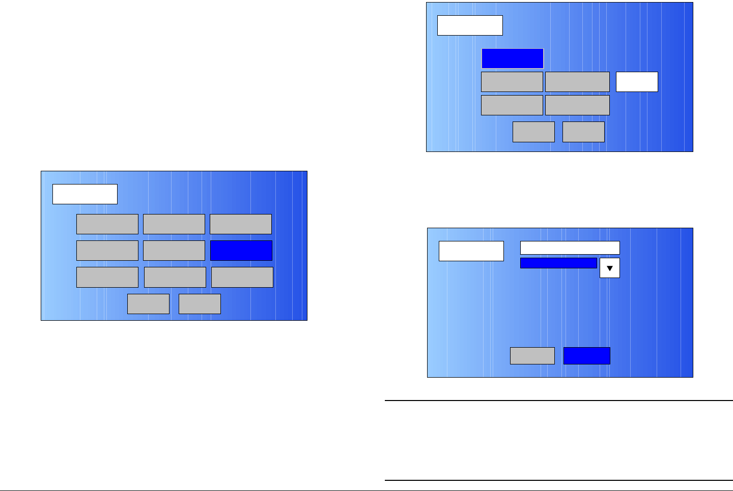
Figure 5-70: Operation Mode Screen
9. Select the ASI option button and observe the ASI
screen is displayed. See Figure 5-71 on page 5-32.
! @ # $ % ^ & * ( ) _ +
Q W E R T Y U I O P { }
A S D F G H J K L :
Z X C V B N M < > ?
Shift BS
Clear CancelEnter
“
Operation Mode
Back
COFDM FMT ASI
IP
SCM
LMS-T
Save As Preset
DVBS
MPEG
Main
Advanced Operations 5-32MTX5000 User and Technical Manual
Figure 5-71: ASI Screen - Typical
10. Select the FEC pull-down menu and select the 1/2,
2/3, 3/4, 5/6, or 7/8 option, as required.
11. Select the Guard Interval pull-down menu and select
the 1/32, 1/16, 1/8, or 1/4 option, as required.
12. Select the Constellation pull-down menu and select
QPSK, 16-QAM, or 64-QAM, as required.
13. Select the RF B/W pull-down menu and select 6 MHZ,
7 MHZ, or 8 MHZ, as required.
14. Select the Back option button and observe the
Operation Mode screen is displayed. See Figure 5-
72.
ASI
Back
FEC Guard Interval Constellation
1/8
RF B/W
3/4 QPSK
8 MHz
Main
Figure 5-72: Operation Mode Screen
Note When the Save As Preset screen is displayed in
the following step, the Preset Text and Save text
boxes will display the name and identification of the
digital ASI Preset currently being used as the
digital ASI “make-from” for this custom Preset.
15. Select the Save As Preset option button and observe
the Save As Preset screen is displayed. See
Figure 5-73.
Figure 5-73: Save As Preset Screen - Typical
Operation Mode
Back
COFDM FMT ASI
IP
SCM
LMS-T
Save As Preset
DVBS
MPEG
Main
Save As Preset
Back
Preset Text Digital – COFDM QPSK
8,3/4,1/8,ASI
Save 5
Advanced Operations 5-33MTX5000 User and Technical Manual
Notes In the following steps, if a factory default digital ASI
Preset was used as a “make-from” to prepare this
custom Preset, the Preset Text text box and Save
text box must be changed. You cannot change
or overwrite any factory default Presets!
If a custom digital ASI Preset was used as a
“make-from” to prepare this custom Preset, a brief
description of the custom Preset must be entered
in the Preset Text text box for easy identification
purposes.
16. Select the Preset Text option button and observe that
the keyboard screen is displayed. See Figure 5-74.
Figure 5-74: Keyboard Screen
17. Enter a unique digital ASI Preset description, as
required, and select the Enter key.
18. Observe the Save As Preset screen is displayed and
the Preset Text text box displays the Preset
description.
! @ # $ % ^ & * ( ) _ +
Q W E R T Y U I O P { }
A S D F G H J K L :
Z X C V B N M < > ?
Shift BS
Clear CancelEnter
“
Notes When saving the new custom digital ASI Preset in
the following step, the Preset number will
automatically be increased to the next available
Preset number to avoid overwriting an existing
Preset.
If you wish to overwrite the existing Preset number
(unless it is a factory default Preset), enter the
Preset number to be overwritten. A warning
message will be displayed asking “Are you
sure?”. Select the Yes option button.
Once an existing custom Preset is overwritten, it
cannot be recovered. It must be re-entered from
scratch.
19. Select the Save option button and observe the
numeric keypad is displayed. See Figure 5-75.
Figure 5-75: Numeric Keypad
1 2 3
4
7
5 6
8 9
CLR 0ESC
ENT
Next Available
Preset Number
Advanced Operations 5-34MTX5000 User and Technical Manual
Notes When saving Presets in the following steps, Preset
A thru Preset J are factory default Presets. The
factory default Preset numbers cannot be changed.
Notes To change the default Preset number, perform step
20 and go to step 21.
To accept the next available Preset number, go to
step 21
20. Select the CLR key and enter the Preset number
required.
21. Select the ENT key and observe the Are you sure?
confirmation screen is displayed. See Figure 5-76.
Figure 5-76: Confirmation Screen
22. Select the YES option button and observe the Please
Wait! message box is displayed. See Figure 5-77.
No
Are you sure?
Yes
Figure 5-77: Please Wait Message Box
23. After a short delay, observe the Save As Preset
screen is displayed.
24. Select the Main option button and observe the Main
screen is displayed.
5.4.4 Create or Update Digital LMS-T Preset
Configuration Settings in Local Mode
The procedure required to create a new custom digital LMS-T
Preset configuration or to update an existing digital LMS-T
Preset configuration is contained in the following steps.
When preparing a new digital LMS-T Preset, you must first select
an existing digital LMS-T Preset from either the digital LMS-T
factory default Preset or from your own custom digital LMS-T
Presets. The selected Preset will be used as a “make-from” to
prepare the new digital LMS-T Preset configuration.
Please note that while factory default Presets may be used to
prepare a new Preset configuration, these factory default
Presets cannot be changed or deleted. They can only be
used as “make-froms”.
When the new configuration is prepared using the factory default
Preset, it cannot be saved with the factory Preset number or
Preset name. A new Preset number and Preset name must be
assigned to the new Preset.
No
Please Wait!
Yes
Advanced Operations 5-35MTX5000 User and Technical Manual
When using a custom Preset as a “make-from”, the new Preset
should be saved with a new Preset number. When you save the
new Preset, the Preset number will automatically be increased to
the next available Preset number. If you select an existing
Preset number when saving the new Preset, the original custom
Preset will be overwritten and cannot be recovered. The only
way to restore a Preset that has been overwritten is to re-enter
the custom Preset data from scratch.
If you are updating configuration settings on an existing custom
Preset, when you save the configuration settings, the Preset
number will automatically be increased to the next available
Preset number. You must enter and save the configuration
settings using the original Preset number.
Note In the following steps, the color LCD display option
buttons and pull-down menu options may be
selected using either the touch screen or the
function keys and the SEL key.
1. Verify the MTX5000 IDU is powered up. See
”Powering the MTX5000 System” on page 3-7.
2. Observe the Main screen is displayed. See Figure 5-
78.
Figure 5-78: Main Screen - Typical
3. Select the L/R option button for L (local mode), as
required.
Notes If you are updating an existing digital LMS-T Preset
configuration, select the Preset to be updated in
the following step.
If you are creating a new digital LMS-T Preset
configuration, any digital LMS-T Preset may be
selected in the following step.
4. Perform “Select Preset” on page 3-24 to select the
digital LMS-T Preset required to be updated or to be
used as a “make-from”.
5. Select the Main screen PA operation button for PA
Off, as required.
6. Select the Main screen Setup option button and
observe the Setup screen is displayed. See Figure 5-
79 on page 5-36.
Channel 1 0Offset
Antenna Ant. Pol.Antenna1 H
RFU1
No RF
RF Band
Preset A Analog
4.83 & 5.8, 3MHz Vid Dev
RF Output XX
dBm
<- Status Setup Status ->
PA Off
SUM
ODU
IDU
RF
L/R
L
L
PA
Operation
Button
Advanced Operations 5-36MTX5000 User and Technical Manual
Figure 5-79: Setup Screen
7. Select the User option button and observe the
keyboard screen is displayed. See Figure 5-80.
Figure 5-80: Keyboard Screen
8. Enter your password, select the Enter key, and
observe the Operation Mode screen is displayed.
See Figure 5-81.
Setup
User
Main
Radio
! @ # $ % ^ & * ( ) _ +
Q W E R T Y U I O P { }
A S D F G H J K L :
Z X C V B N M < > ?
Shift BS
Clear CancelEnter
“
Figure 5-81: Operation Mode Screen
9. Select the LMS-T option button and observe the
LMS-T screen is displayed. See Figure 5-82.
Figure 5-82: LMS-T Screen - Typical
10. Use the Constellation pull-down menu to select
QPSK or 16-QAM, as required.
Note In the following step, 2/3 is the only LMS-T FEC
option available.
Operation Mode
Back
COFDM FMT ASI
IP
SCM
LMS-T
Save As Preset
DVBS
MPEG
Main
LMS-T
Main
FEC
Guard IntervalConstellation
1/8
RF B/W
2/3
16-QAM 10 MHz
Back Submit
Advanced Operations 5-37MTX5000 User and Technical Manual
11. Observe the FEC (Forward Error Correction) pull-
down menu indicates 2/3.
12. Use the RF B/W pull-down menu to select 10 MHZ or
20 MHZ, as required.
13. Use the Guard Interval pull-down menu and select
1/16 or 1/8, as required.
14. Select the Submit option button.
15. Select the Back option button and observe the
Operation Mode screen is displayed. See Figure 5-
83.
Figure 5-83: Operation Mode Screen
16. Select the MPEG option button and observe the
MPEG screen is displayed. See Figure 5-84.
Operation Mode
Back
COFDM FMT ASI
IP
SCM
LMS-T
Save As Preset
DVBS
MPEG
Main
Figure 5-84: MPEG Screen - Typical
17. Select the Video In option button and observe the
Video In screen is displayed. See Figure 5-85.
Figure 5-85: Video In Screen 1 - Typical
Note In the following step, select an Input option
applicable to the licensed options contained in your
MTX5000 IDU only. Selection of an option that is
not licensed in your radio will cause the IDU to
operate in the NTSC default mode.
MPEG
Back
Video In
Audio In
Encoder
NormalSpectrum Invert
Encoding
Main
Video In
Back
Input
NTSC
Video In2
Advanced Operations 5-38MTX5000 User and Technical Manual
18. Use the Input pull-down menu to select the video
input option required.
19. Select the Video In2 option button and observe the
Video In screen 2 is displayed. See Figure 5-86.
Figure 5-86: Video In Screen 2 - Typical
20. Select the Noise Reduction option button for On or
Off, as required.
21. Select the SDI Auto Line option button for On or Off,
as required.
22. Select the HD Test Pattern option button for On or
Off, as required.
23. Select the Back option button and observe the Video
In screen is displayed.
24. Select the Back option button and observe the MPEG
screen is displayed. See Figure 5-87.
Video In
Back
Noise Reduction
SDI Auto Line
Off
Off HD Test Pattern Off
Main
Figure 5-87: MPEG Screen - Typical
25. Select the Audio In option button and observe the
AUDIO 1 screen is displayed. See Figure 5-88.
Figure 5-88: AUDIO 1 Screen - Typical
26. Use the Mode pull-down menu to select Stereo or
Dual Mono, as required.
27. Use the Standard pull-down menu to select Off,
MPEG Layer II, Linear PCM, or MPEG Layer I, as
required.
MPEG
Back
Video In
Audio In
Encoder
NormalSpectrum Invert
Encoding
Main
AUDIO 1
Back
Mode Standard Bit Rate
MPEG Layer II
Input
Dual Mono 192 Kbps
Analog
Audio 2Main
Advanced Operations 5-39MTX5000 User and Technical Manual
28. Use the Bit Rate pull-down menu to select 128 Kbps,
160 Kbps, 192 Kbps, 224 Kbps, 256 Kbps, 320
Kbps, or 384 Kbps, as required.
29. Use the Input pull-down menu to select Test Tone,
Analog, or SDI Emb, as required.
30. Select the Audio 2 option button and observe the
AUDIO 2 screen is displayed. See Figure 5-89.
Figure 5-89: AUDIO 2 Screen - Typical
31. Use the Mode pull-down menu to select Stereo or
Dual Mono, as required.
32. Use the Standard pull-down menu to select Off,
MPEG Layer II, Linear PCM, or MPEG Layer I, as
required.
33. Use the Bit Rate pull-down menu to select 128 Kbps,
160 Kbps, 192 Kbps, 224 Kbps, 256 Kbps, 320
Kbps, or 384 Kbps, as required.
34. Use the Input pull-down menu to select Test Tone,
Analog, SDI Emb, AES-EBU, or Channel Ide, as
required.
35. Select the Back option button and observe the AUDIO
1 screen is displayed.
AUDIO 2
Back
Mode Standard Bit Rate
MPEG Layer II
Input
Dual Mono 192 Kbps
Analog
Main
Balance
Unbalanced
36. Select the Back option button and observe the MPEG
screen is displayed. See Figure 5-90.
Figure 5-90: MPEG Screen - Typical
37. Select the Spectrum Invert option button to select
Normal or Inverted, as required.
38. Select the Encoder option button and observe the
Encoder screen is displayed. See Figure 5-91.
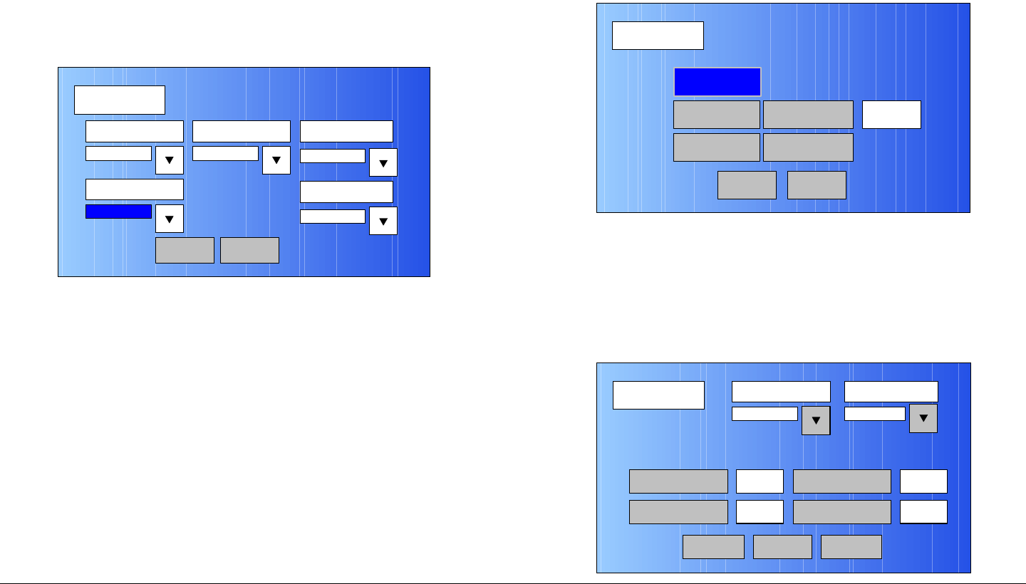
Figure 5-91: Encoder Screen - Typical
MPEG
Back
Video In
Audio In
Encoder
NormalSpectrum Invert
Encoding
Main
Encoder
Back
Mode Bit Rate
Low delay
4.9 Mb/s
Bit Rate
On
MP@ML
Encoder 2
Bit Rate Auto GOP Length 15
Main
ASI Bit Rate 5.529
Mb/s
Advanced Operations 5-40MTX5000 User and Technical Manual
39. Select the Mode pull-down menu and select Standard
or Low delay, as required.
40. Select the Bit Rate pull-down menu and select
MP@ML or 422P@ML, as required.
Notes In the following step, if the Bit Rate Auto option
button option selected is On, the Bit Rate option
button will be inactive (greyed out). Go to step 43.
If the Bit Rate Auto option button option selected
is Off, the Bit Rate option button will be active. Go
to step 42.
41. Select the Bit Rate Auto option button for Off or On,
as required.
42. Observe the Bit Rate option button is active. Select
the Bit Rate option button and observe the numeric
keypad is displayed. See Figure 5-92.
Figure 5-92: Numeric Keypad
43. Enter the bit rate required, select the ENT key, and
observe the Encoder screen is displayed.
44. Select the GOP Length option button and observe the
numeric keypad is displayed. See Figure 5-93.
123
ESC
0
4
7
5 6
8 9
DEL 0ESC
ENT
Figure 5-93: Numeric Keypad
45. Enter the Group of Pictures (GOP) number required,
select the ENT key, and observe the Encoder screen
is displayed.
46. Select the Encoder 2 option button and observe the
Encoder screen is displayed. See Figure 5-94.
Figure 5-94: Encoder Screen 2 - Typical
47. Select the Horiz Resolution pull-down menu and
select 720, 704, 544, 528, 480, or 352, as required.
48. Select the Aspect Ratio pull-down menu and select
4:3 or 16:9, as required.
123
4
7
5 6
8 9
CLR 0ESC
ENT
Encoder
Back
Horiz Resolution Aspect Ratio
720
PID
Off
4:3
PTS per Picture VBI Off
Main
Remux Off
Advanced Operations 5-41MTX5000 User and Technical Manual
49. Select the PID option button and observe the PID
screen is displayed. See Figure 5-95.
Figure 5-95: PID Screen - Typical
Notes To select the default PID settings, go to step 50.
To enter individual PID settings, go to step 51.
50. Select the DEFAULT option button and observe the
default PID settings are displayed. Go to step 71.
51. Select the DATA option button and observe the
numeric keypad is displayed.
52. Enter the DATA PID required, select the ENT key, and
observe the PID screen is displayed.
53. Select the AUDIO A option button and observe the
numeric keypad is displayed.
54. Enter the AUDIO A PID required, select the ENT key,
and observe the PID screen is displayed.
55. Select the PMT option button and observe the numeric
keypad is displayed.
PID
Main
DEFAULT
PMT
300
12 AUDIO B 201
DATA
AUDIO A
100
200
VIDEO PCR 8190
Back Next
56. Enter the PMT PID required, select the ENT key, and
observe the PID screen is displayed.
57. Select the AUDIO B option button and observe the
numeric keypad is displayed.
58. Enter the AUDIO B PID required, select the ENT key,
and observe the PID screen is displayed.
59. Select the VIDEO option button and observe the
numeric keypad is displayed.
60. Enter the Video PID required, select the ENT key, and
observe the PID screen is displayed.
61. Select the PCR option button and observe the numeric
keypad is displayed.
62. Enter the PCR PID required, select the ENT key, and
observe the PID screen is displayed.
63. Select the Next option button and observe the PID-2
screen is displayed. See Figure 5-96.
Figure 5-96: PID-2 Screen - Typical
64. Select the Program ID option button and observe the
numeric keypad is displayed. See Figure 5-97 on
page 5-42.
PID-2
Main
Program ID
Transport ID 1
Network ID3 1
Back
Advanced Operations 5-42MTX5000 User and Technical Manual
Figure 5-97: Numeric Keypad
65. Enter the Program ID PID required, select the ENT
key, and observe the PID-2 screen is displayed.
66. Select the Network ID option button and observe the
numeric keypad is displayed.
67. Enter the Network ID PID required, select the ENT
key, and observe the PID-2 screen is displayed.
68. Select the Transport ID option button and observe the
numeric keypad is displayed.
69. Enter the Transport ID PID required, select the ENT
key, and observe the PID-2 screen is displayed.
70. Select the Back option button and observe the PID
screen is displayed.
71. Select the Back option button and observe the
Encoder screen is displayed.
72. Select the Remux option button for On or Off, as
required.
73. Select the PTS per Picture option button to select On
or Off, as required.
74. Select the Back option button and observe the
Encoder screen is displayed.
123
ESC
0
4
7
5 6
8 9
DEL 0ESC
ENT
75. Select the Back option button and observe the MPEG
screen is displayed. See Figure 5-98.
Figure 5-98: MPEG Screen - Typical
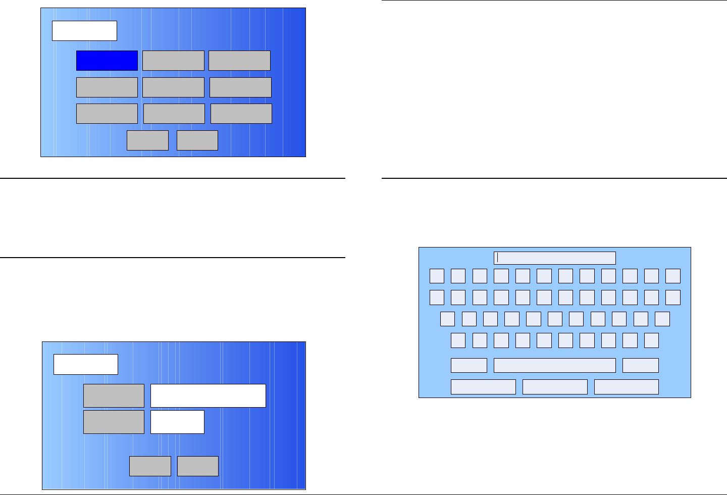
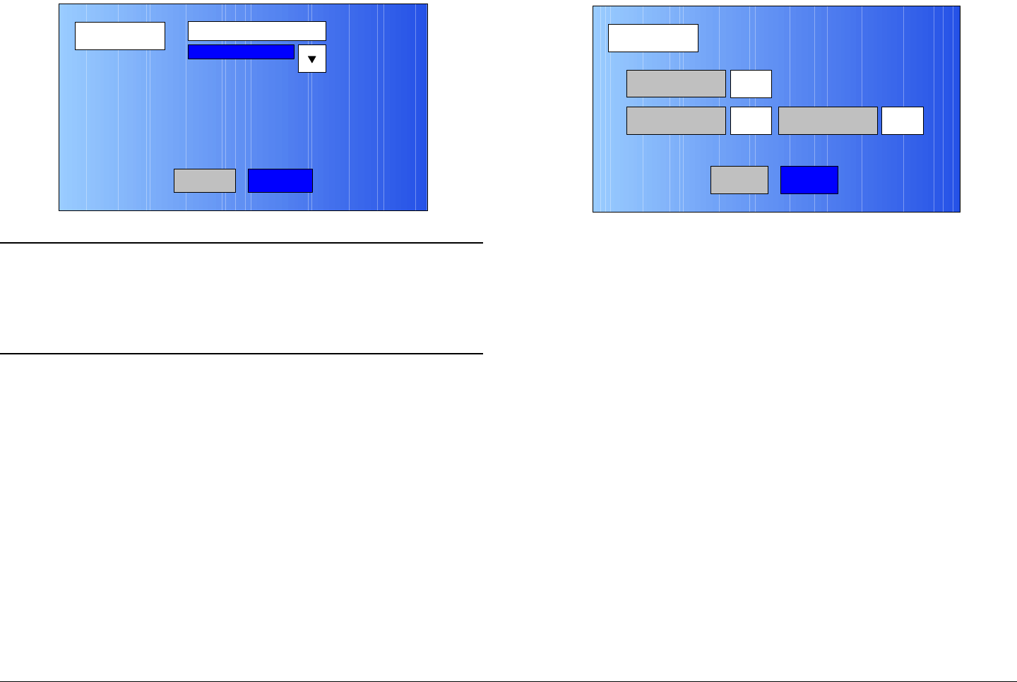
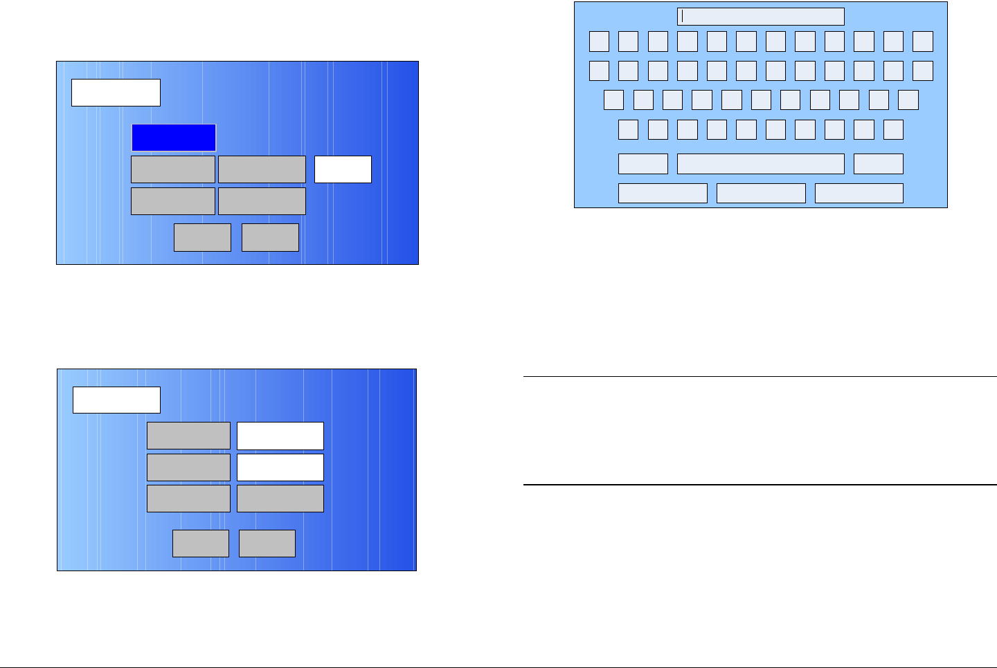
76. Select the Encoding option button and observe the
Encoding screen is displayed. See Figure 5-99.
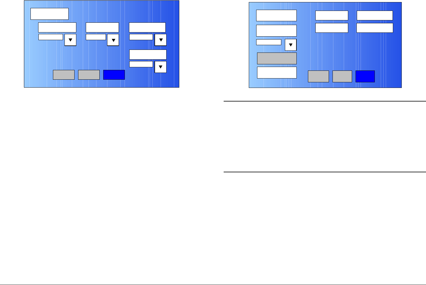
Figure 5-99: Encoding Screen - Typical
77. Select the Service Name option button and observe
the keyboard screen is displayed. See Figure 5-100.
MPEG
Back
Video In
Audio In
Encoder
NormalSpectrum Invert
Encoding
Main
Encoding
Back
Service Name
Network Name
EBS/BISS Wayside data
Service 01
Main
Advanced Operations 5-43MTX5000 User and Technical Manual
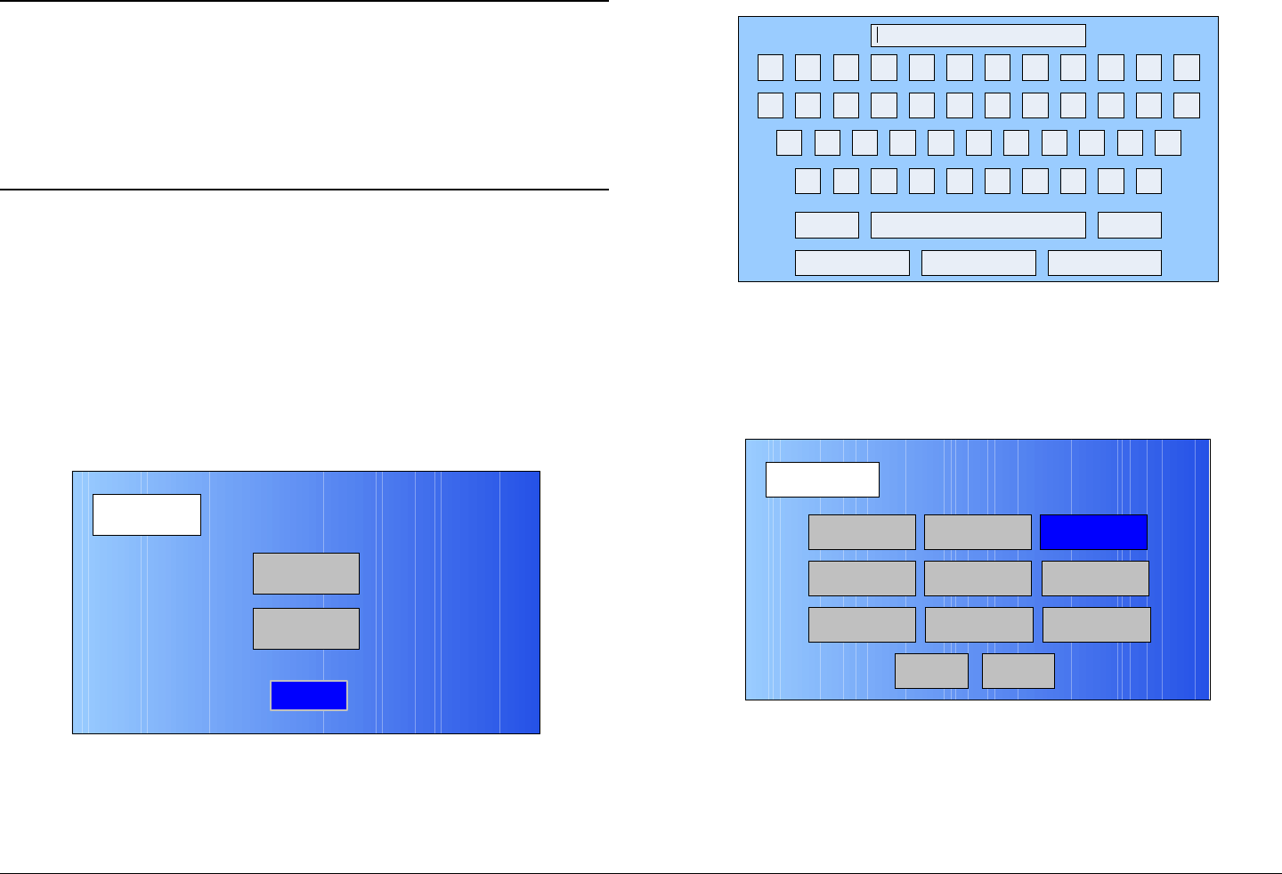
Figure 5-100: Keyboard Screen
78. Enter the service name required, select the Enter key,
and observe the Encoding screen is displayed.
79. Select the Network Name option button and observe
the keyboard screen is displayed.
80. Enter the network name required, select the Enter
key, and observe the Encoding screen is displayed.
Notes If your MTX5000 IDU contains a licensed EBS or
BISS encryption option, go to step 81.
If your MTX5000 IDU does not contain a licensed
EBS or BISS encryption option, go to step 87.
81. Observe the EBS/BISS option button is active (not
greyed-out).
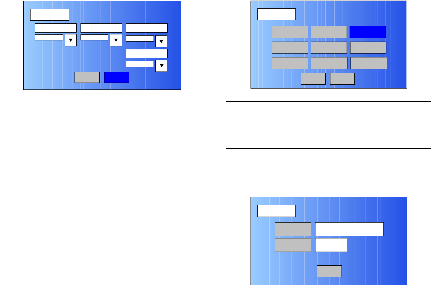
82. Select the EBS/BISS option button and observe the
Encryption screen is displayed. See Figure 5-101.
! @ # $ % ^ & * ( ) _ +
Q W E R T Y U I O P { }
A S D F G H J K L :
Z X C V B N M < > ?
Shift BS
Clear CancelEnter
“
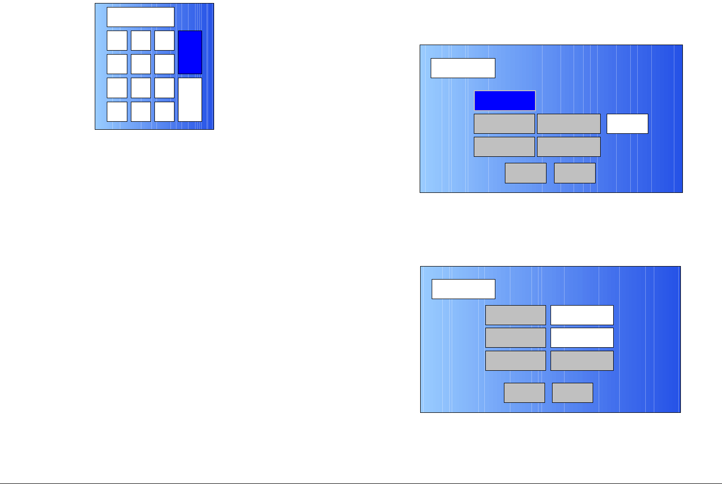
Figure 5-101: Encryption Screen
Notes You can only have one licensed encryption option
contained in your MTX5000 IDU.
When the Scrambling pull-down menu EBS,
BISS-1, or BISS-E option is selected in the
following step, the selected option key will be
active, but the two remaining option buttons will
become inactive (greyed-out).
83. Select the Scrambling pull-down menu EBS, BISS-1,
or BISS-E option, as required, and observe the
selected EBS, BISS-1, or BISS-E Key option button is
active.
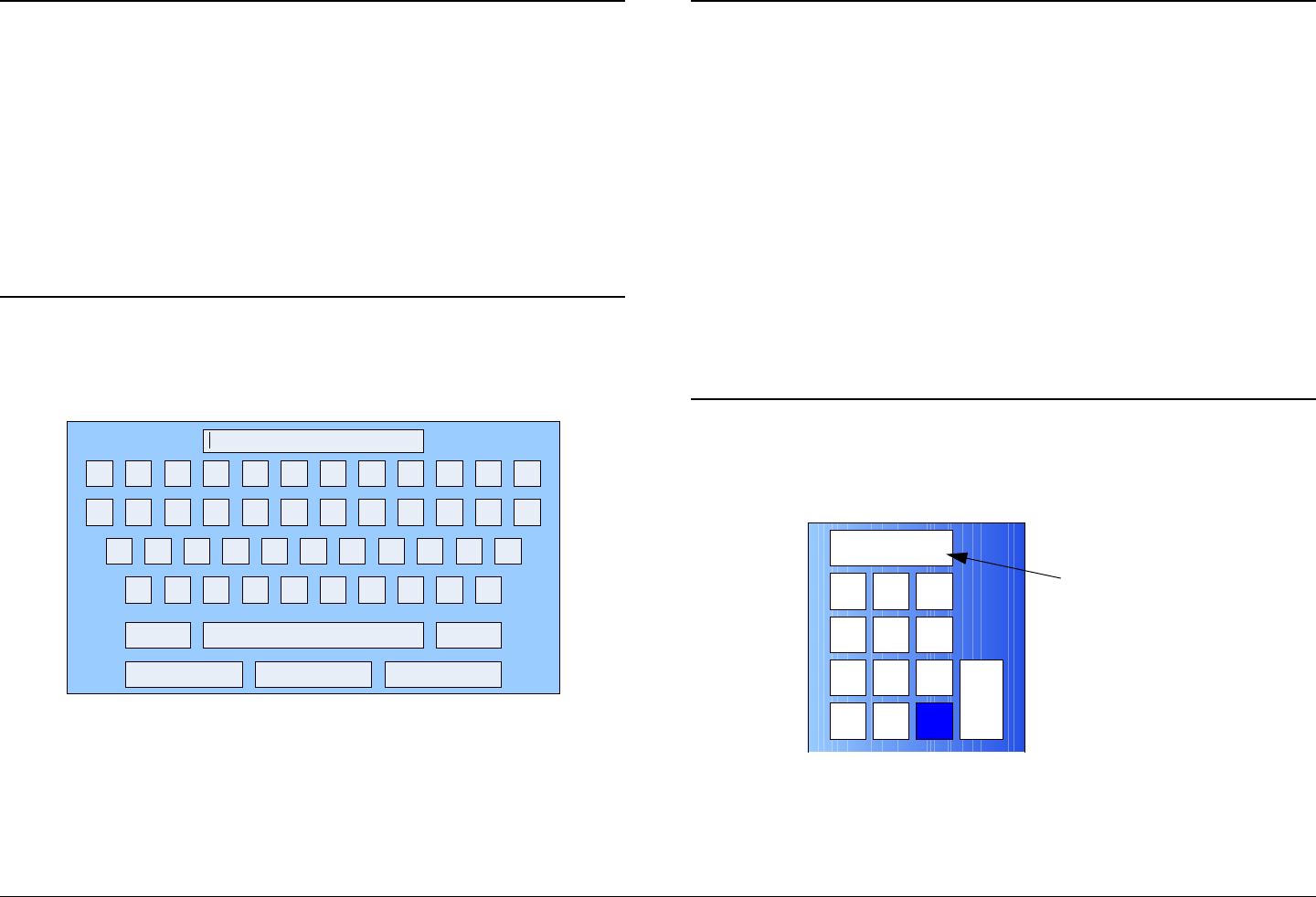
84. Select the EBS, BISS-1, or BISS-E Key option button,
as required, and observe the alphanumeric keypad is
displayed. See Figure 5-102 on page 5-44.
Encryption
Back
EBS Key
BISS-1 Key
BISS-E Key
xx Scrambling
xx
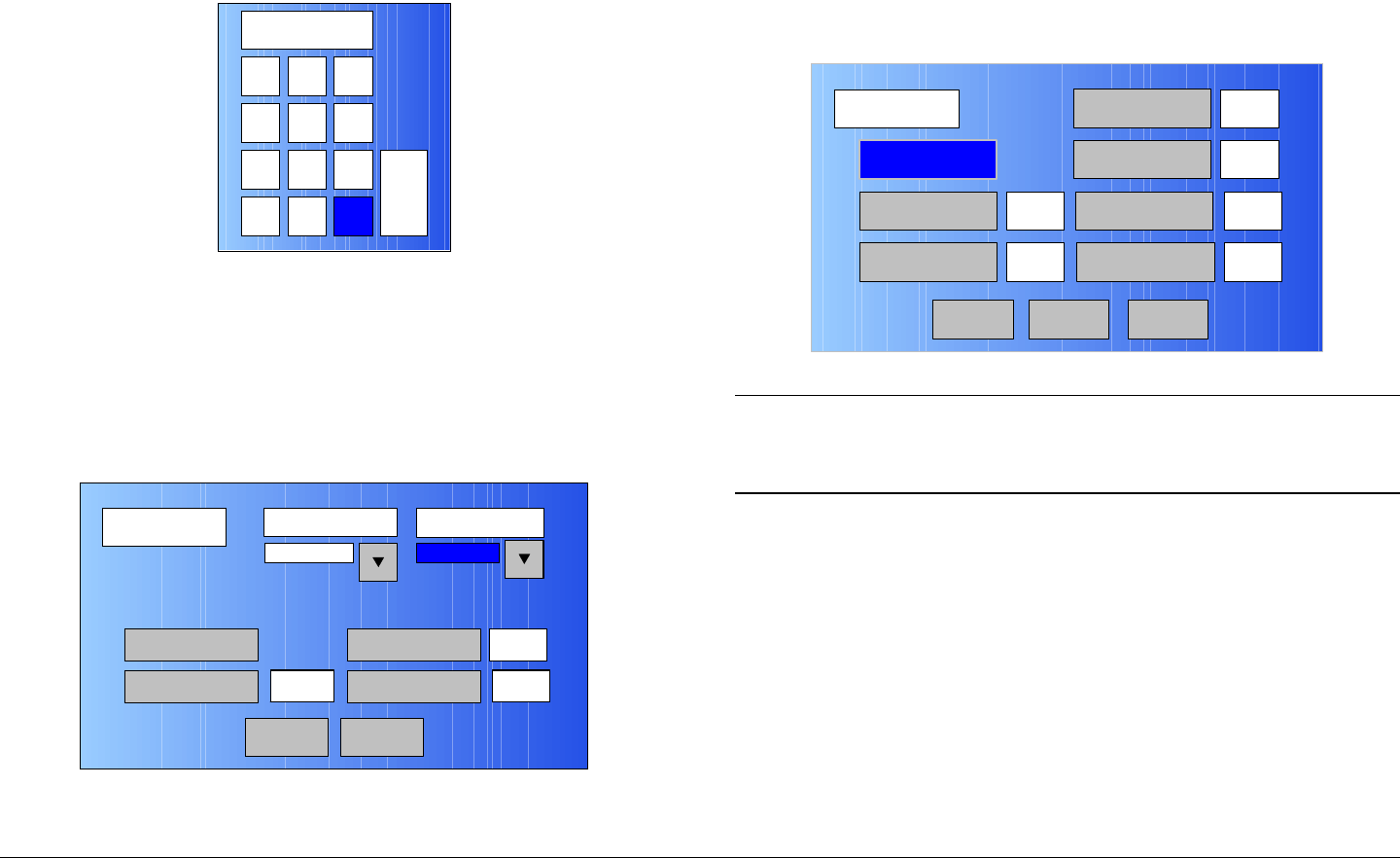
xx
Main
Advanced Operations 5-44MTX5000 User and Technical Manual
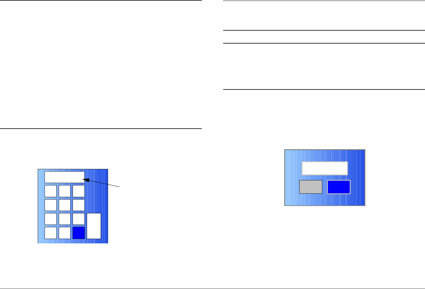
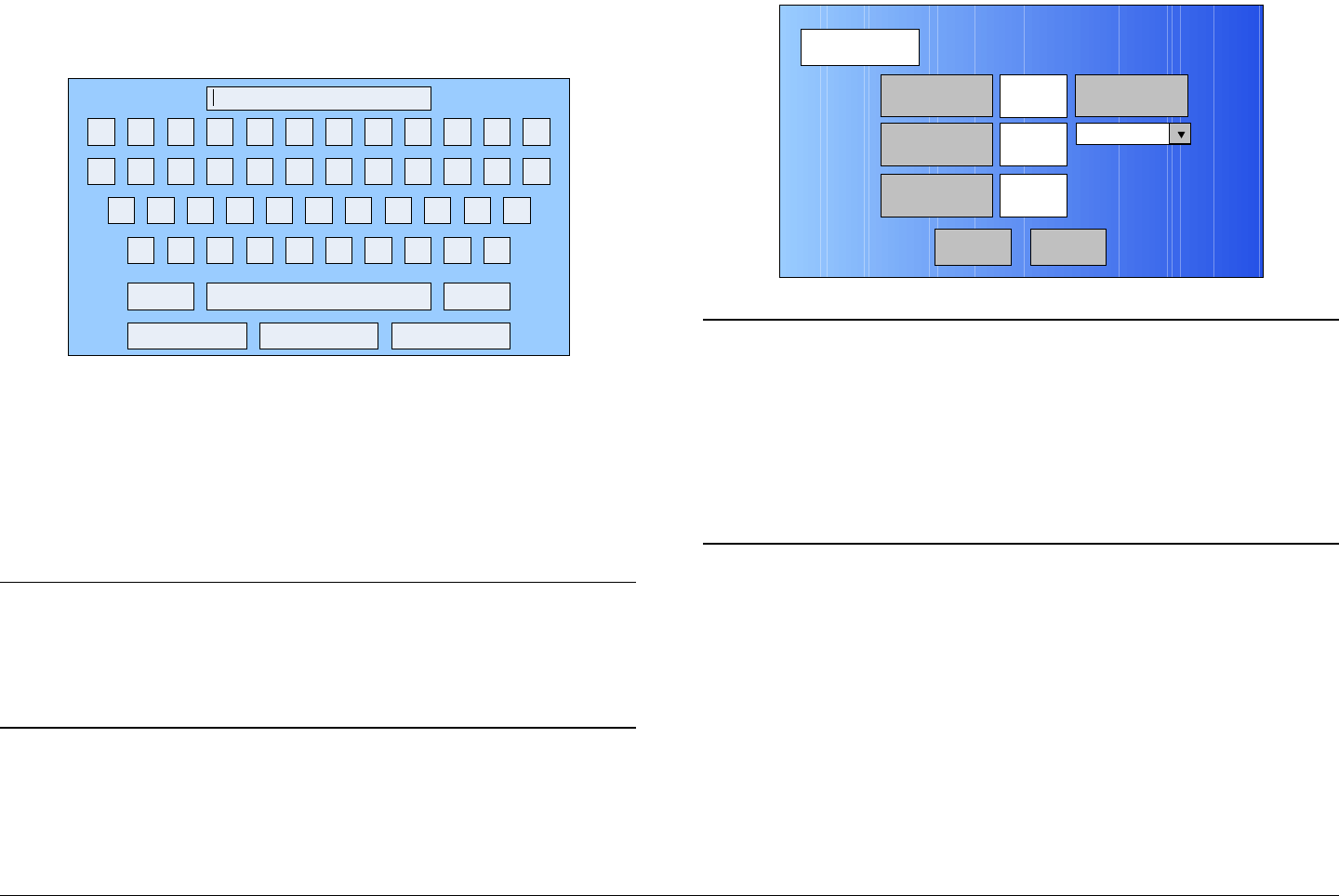
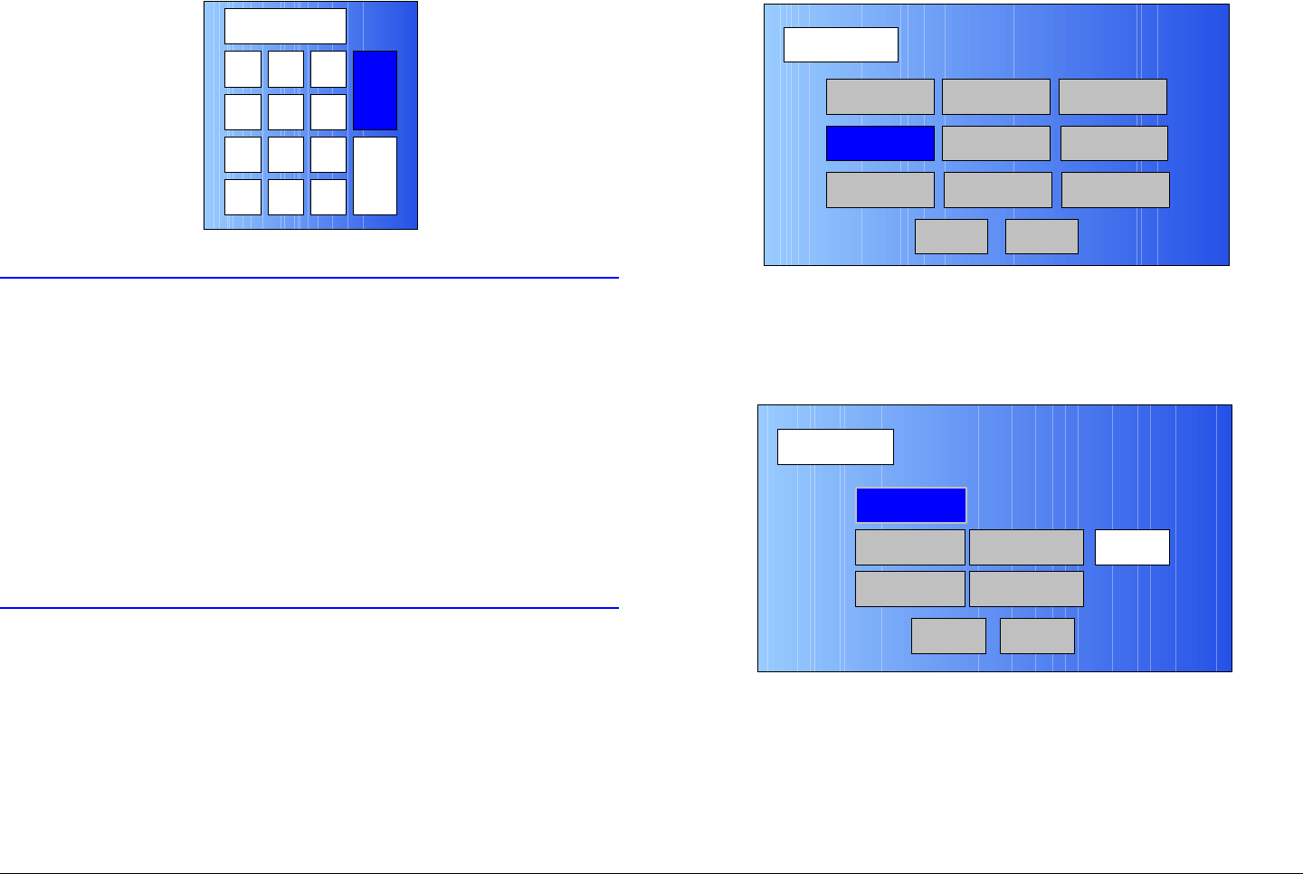
Figure 5-102: Alphanumeric Keypad
Note When the Encryption screen is displayed and the
encryption key is entered in the following step, the
encryption key will not be displayed.
85. Enter your encryption key, select the ENT key, and
observe the Encryption screen is displayed.
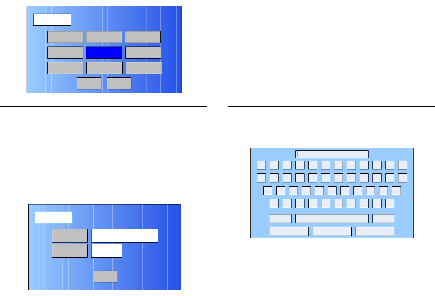
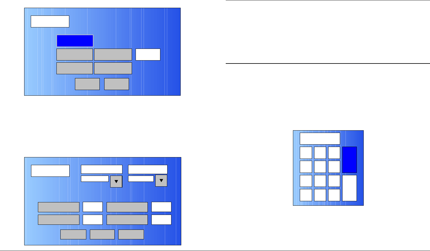
86. Select the BACK option button and observe the
Encoding screen is displayed. See Figure 5-103.
Figure 5-103: Encoding Screen - Typical
1 2 3
0
4
7
5 6
8 9
DEL CAN 0ENT
A D
B E
C F
Encoding
Back
Service Name
Network Name
EBS/BISS Wayside data
Service 01
Main
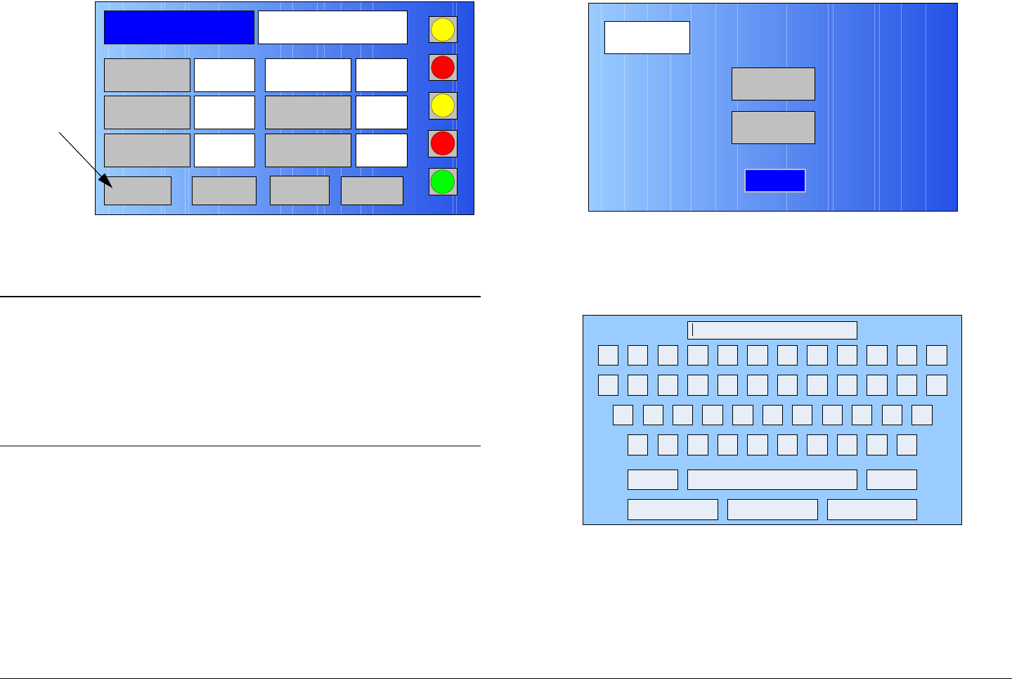
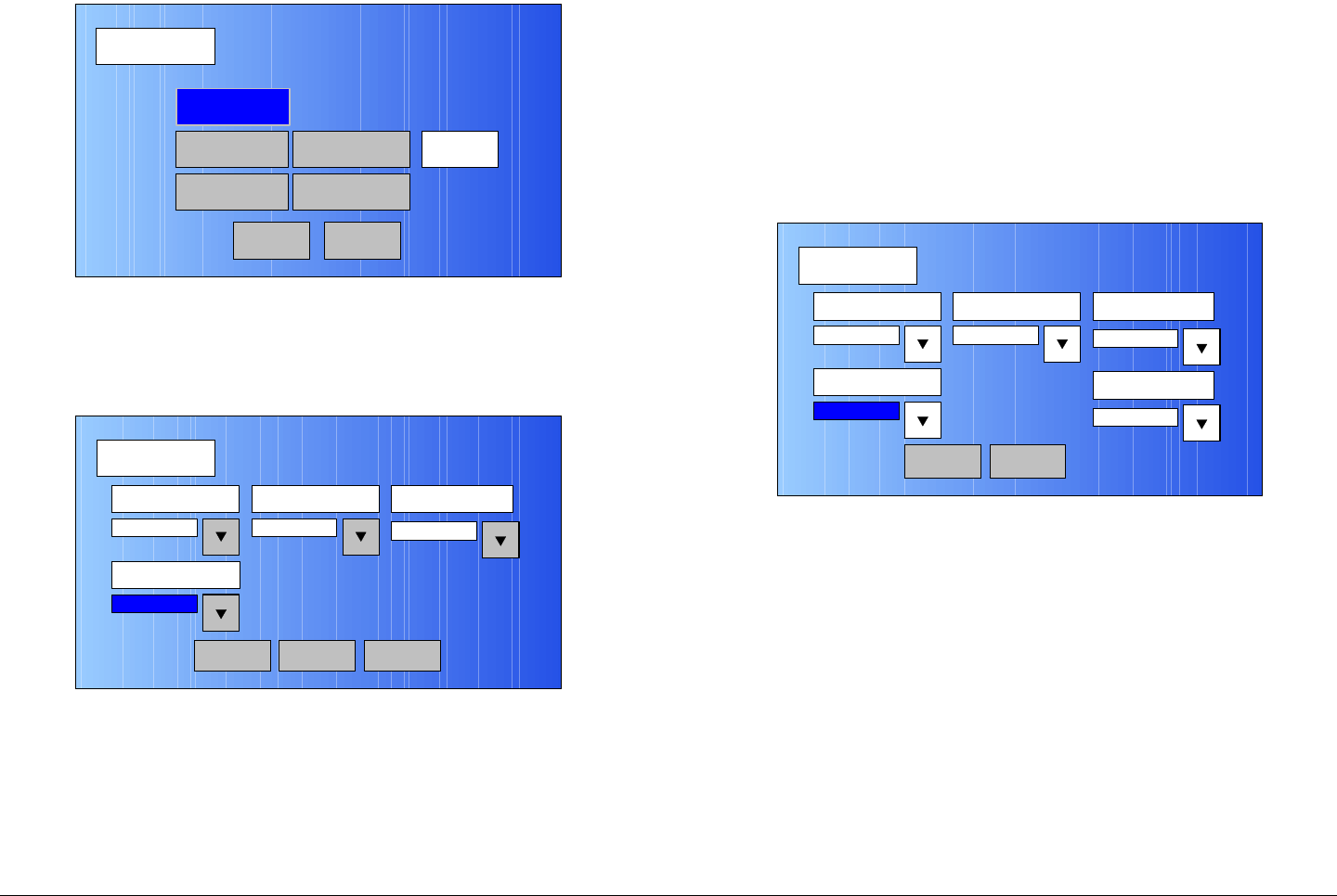
87. Select the Wayside data option button and observe
the Wayside Data screen is displayed. See Figure 5-
104.
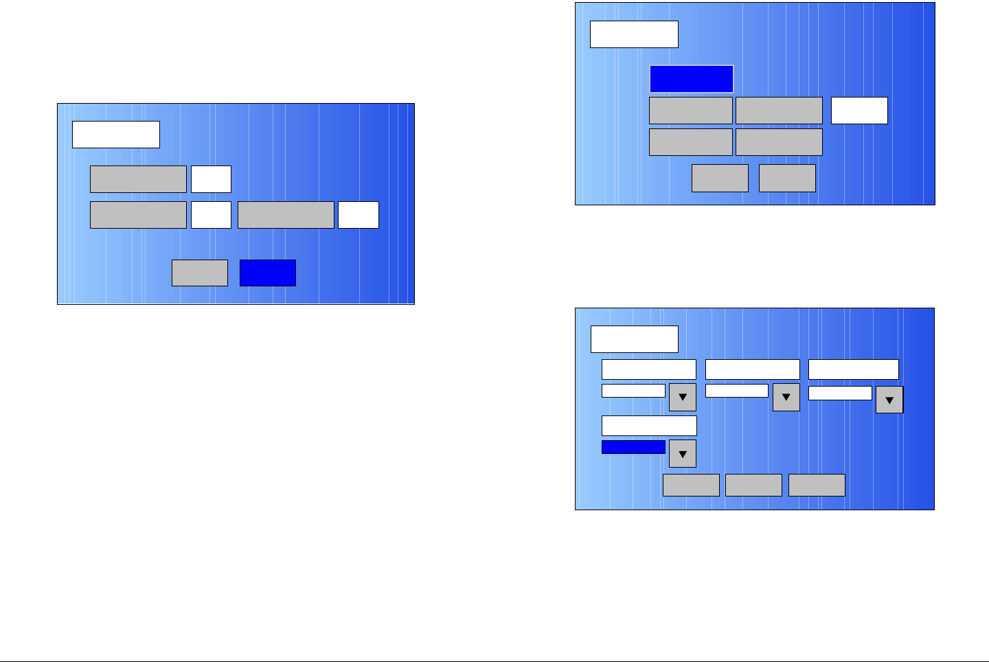
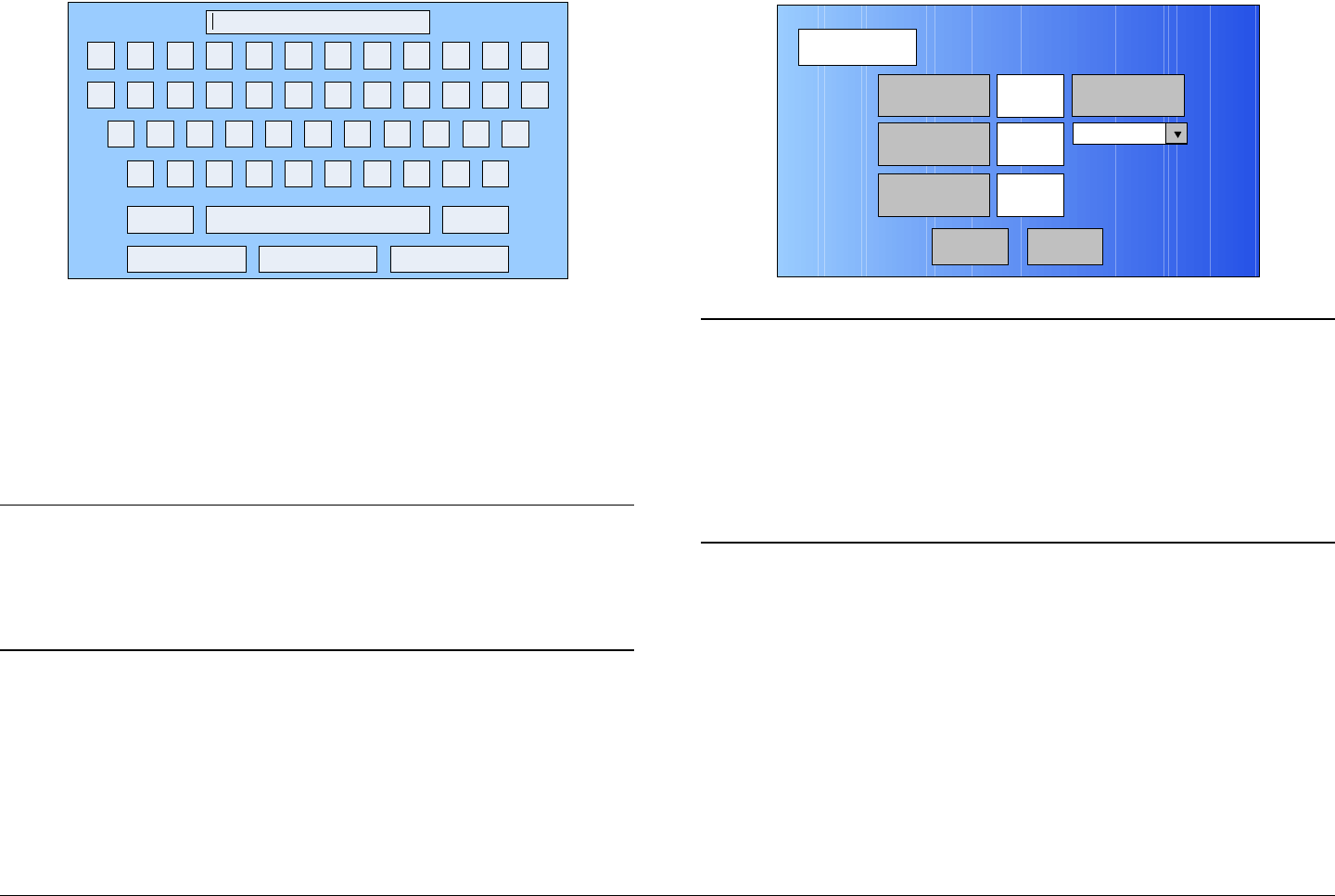
Figure 5-104: Wayside Data Screen - Typical
88. Select the Data Enable pull-down menu and select
the Off, TTV Format, CJM2 Format, or Low Delay
CJM2 option, as required.
89. Select the Baud Rate pull-down menu and select the
1200, 2400, 4800, 9600, 19200, or 38400 option, as
required.
90. Select the Back option button and observe the
Encoding screen is displayed.
91. Select the Back option button and observe the MPEG
screen is displayed.
92. Select the Back option button and observe the
Operation Mode screen is displayed. See Figure 5-
105 on page 5-45.
Wayside Data
Back
Data Enable Baud Rate
Off 2400
Main
Advanced Operations 5-45MTX5000 User and Technical Manual
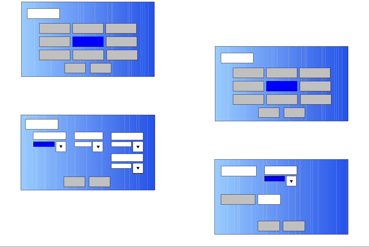
Figure 5-105: Operation Mode Screen
Note When the Save As Preset screen is displayed in
the following step, the Preset Text and Save text
boxes will display the name and identification of the
digital LMS-T Preset currently being used as the
digital LMS-T “make-from” for this custom Preset.
93. Select the Save As Preset option button and observe
the Save As Preset screen is displayed. See
Figure 5-106.
Figure 5-106: Save As Preset Screen - Typical
Operation Mode
Back
COFDM FMT ASI
IP
SCM
LMS-T
Save As Preset
DVBS
MPEG
Main
Save As Preset
Back
Preset Text Digital – LMS-T 16QAM
4:2:0,10,2/3,1/8,HD 1080i
Save 6
Notes In the following steps, if a factory default digital
LMS-T Preset was used as a “make-from” to
prepare this custom Preset, the Preset Text text
box and the Save text box must be changed. You
cannot change or overwrite any factory default
Presets!
If a custom digital LMS-T Preset was used as a
“make-from” to prepare this custom Preset, a brief
description of the custom Preset must be entered
in the Preset Text text box for easy identification
purposes.
94. Select the Preset Text option button and observe that
the keyboard screen is displayed. See Figure 5-107.
Figure 5-107: Keyboard Screen
95. Enter a unique digital LMS-T Preset description, as
required, and select the Enter key.
96. Observe the Save As Preset screen is displayed and
the Preset Text text box displays the Preset
description.
! @ # $ % ^ & * ( ) _ +
Q W E R T Y U I O P { }
A S D F G H J K L :
Z X C V B N M < > ?
Shift BS
Clear CancelEnter
“
Advanced Operations 5-46MTX5000 User and Technical Manual
Notes When saving the new custom digital LMS-T Preset
in the following step, the Preset number will
automatically be increased to the next available
Preset number to avoid overwriting an existing
Preset.
If you wish to overwrite the existing Preset number
(unless it is a factory default Preset), enter the
Preset number to be overwritten. A warning
message will be displayed asking “Are you
sure?”. Select the Yes option button.
Once an existing custom Preset is overwritten, it
cannot be recovered. It must be re-entered from
scratch.
97. Select the Save option button and observe the
numeric keypad is displayed. See Figure 5-108.
Figure 5-108: Numeric Keypad
1 2 3
4
7
5 6
8 9
CLR 0ESC
ENT
Next Available
Preset Number
Notes When saving Presets in the following steps, Preset
A thru Preset J are factory default Presets. The
factory default Preset numbers cannot be changed.
Notes To change the default Preset number, perform step
98 and go to step 99.
To accept the next available Preset number, go to
step 99.
98. Select the CLR key and enter the Preset number
required.
99. Select the ENT key and observe the Are you sure?
confirmation screen is displayed. See Figure 5-109.
Figure 5-109: Confirmation Screen
100. Select the YES option button and observe the Please
Wait! message box is displayed. See Figure 5-110 on
page 5-47.
No
Are you sure?
Yes

Advanced Operations 5-47MTX5000 User and Technical Manual
Figure 5-110: Please Wait Message Box
101. After a short delay, observe the Save As Preset
screen is displayed.
102. Select the Main option button and observe the Main
screen is displayed.
5.4.5 Create or Update Digital DVB-S Preset
Configuration Settings in Local Mode
The procedure required to create a new custom digital DVB-S
Preset configuration or to update an existing digital DVB-S
Preset configuration is contained in the following steps.
When preparing a new digital DVB-S Preset, you must first
select an existing digital DVB-S Preset from either the digital
DVB-S factory default Preset or from your own custom digital
DVB-S Presets. The selected Preset will be used as a “make-
from” to prepare the new digital DVB-S Preset configuration.
Please note that while factory default Presets may be used to
prepare a new Preset configuration, these factory default
Presets cannot be changed or deleted. They can only be
used as “make-froms”.
When the new configuration is prepared using the factory default
Preset, it cannot be saved with the factory Preset number or
Preset name. A new Preset number and Preset name must be
assigned to the new Preset.
No
Please Wait!
Yes
When using a custom Preset as a “make-from”, the new Preset
should be saved with a new Preset number. When you save the
new Preset, the Preset number will automatically be increased to
the next available Preset number. If you select an existing
Preset number when saving the new Preset, the original custom
Preset will be overwritten and cannot be recovered. The only
way to restore a Preset that has been overwritten is to re-enter
the custom Preset data from scratch.
If you are updating configuration settings on an existing custom
Preset, when you save the configuration settings, the Preset
number will automatically be increased to the next available
Preset number. You must enter and save the configuration
settings using the original Preset number.
Note In the following steps, the color LCD display option
buttons and pull-down menu options may be
selected using either the touch screen or the
function keys and the SEL key.
1. Verify the MTX5000 IDU is powered up. See
”Powering the MTX5000 System” on page 3-7.
2. Observe the Main screen is displayed. See Figure 5-
111 on page 5-48.
Advanced Operations 5-48MTX5000 User and Technical Manual
Figure 5-111: Main Screen - Typical
3. Select the L/R option button for L (local mode), as
required.
Notes If you are updating an existing digital DVB-S Preset
configuration, select the Preset to be updated in
the following step.
If you are creating a new digital DVB-S Preset
configuration, any digital DVB-S Preset may be
selected in the following step.
4. Perform “Select Preset” on page 3-24 to select the
digital DVB-S Preset required to be updated or to be
used as a “make-from”.
5. Select the Main screen PA operation button for PA
Off, as required.
6. Select the Main screen Setup option button and
observe the Setup screen is displayed. See Figure 5-
112.
Channel 1 0Offset
Antenna Ant. Pol.Antenna1 H
RFU1
No RF
RF Band
Preset A Analog
4.83 & 5.8, 3MHz Vid Dev
RF Output XX
dBm
<- Status Setup Status ->
PA Off
SUM
ODU
IDU
RF
L/R
L
L
PA
Operation
Button
Figure 5-112: Setup Screen
7. Select the User option button and observe the
keyboard screen is displayed. See Figure 5-113.
Figure 5-113: Keyboard Screen
8. Enter your password, select the Enter key, and
observe the Operation Mode screen is displayed.
See Figure 5-114 on page 5-49.
Setup
User
Main
Radio
! @ # $ % ^ & * ( ) _ +
Q W E R T Y U I O P { }
A S D F G H J K L :
Z X C V B N M < > ?
Shift BS
Clear CancelEnter
“
Advanced Operations 5-49MTX5000 User and Technical Manual
Figure 5-114: Operation Mode Screen
9. Select the COFDM option button and observe the
COFDM screen is displayed. See Figure 5-115.
Figure 5-115: COFDM Screen - Typical
10. Use the FEC (Forward Error Correction) pull-down
menu and select 1/2, 2/3, 3/4, 5/6, or 7/8, as required.
11. Use the Guard Interval pull-down menu and select
1/32, 1/16, 1/8, or 1/4, as required.
12. Use the Constellation pull-down menu to select
QPSK, 16-QAM or 8-PSK, as required.
Operation Mode
Back
COFDM FMT ASI
IP
SCM
LMS-T
Save As Preset
DVBS
MPEG
Main
COFDM
Back
FEC Guard Interval Constellation
1/8
RF B/W
1/2 QPSK
8 MHz
Main
13. Use the RF B/W pull-down menu to select 6 MHZ,
7 MHZ, or 8 MHZ, as required.
14. Select the Back option button and observe the
Operation Mode screen is displayed. See Figure 5-
116.
Figure 5-116: Operation Mode Screen
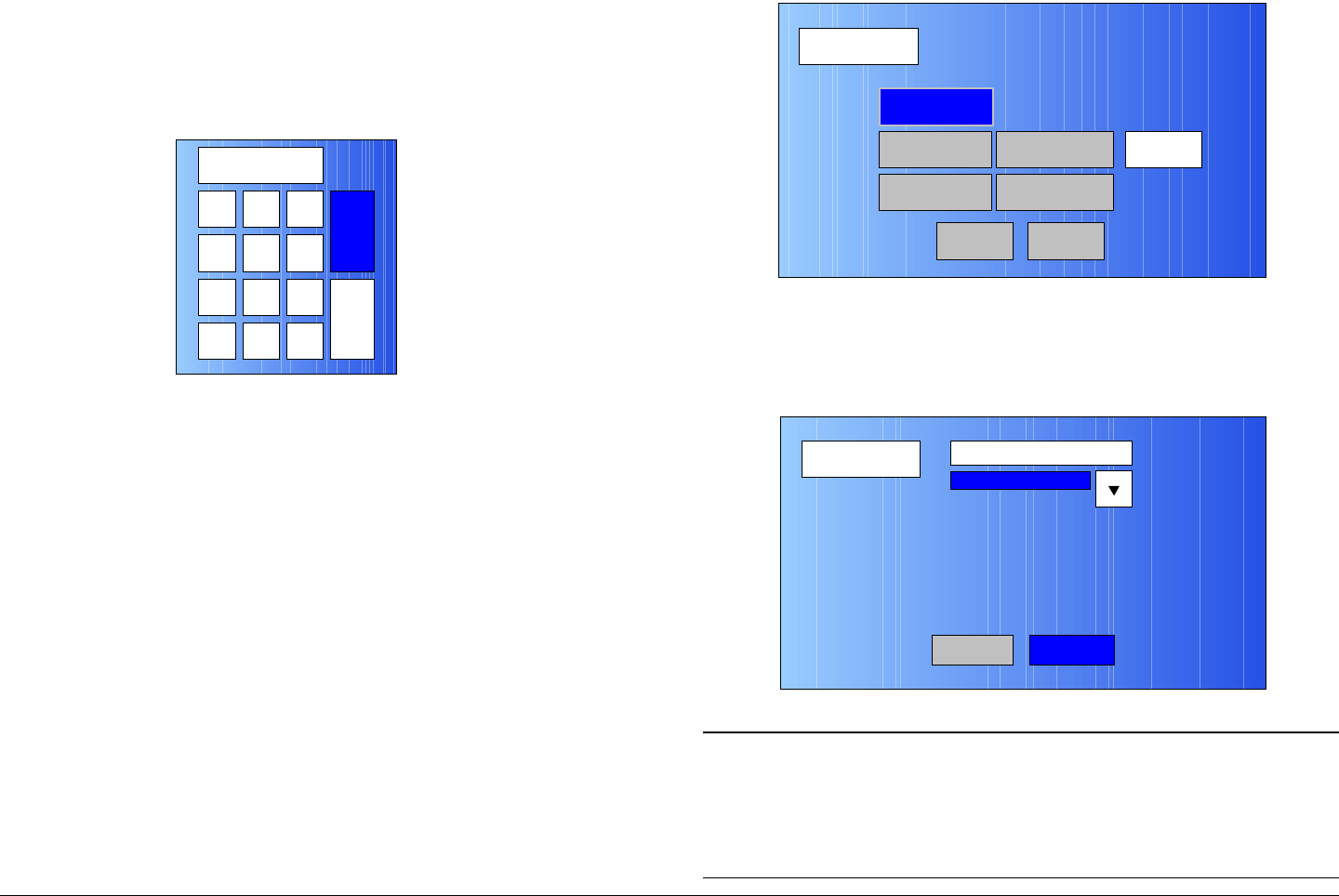
15. Select the DVBS option button and observe the DVBS
screen is displayed. See Figure 5-117.
Figure 5-117: DVBS Screen - Typical
Operation Mode
Back
COFDM FMT ASI
IP
SCM
LMS-T
Save As Preset
DVBS
MPEG
Main
DVBS DVBS Roll Off
Main
Symbol Rate
35%
15.4 Msps
Back
Advanced Operations 5-50MTX5000 User and Technical Manual
16. Use the DVBS Roll Off pull-down menu to select
20%, 25%, or 35%, as required.
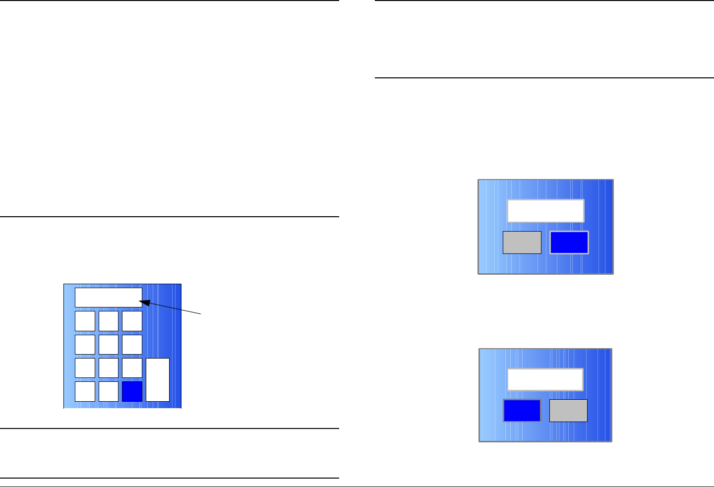
17. Select the Symbol Rate option button and observe
the numeric keypad is displayed. See Figure 5-118.
Figure 5-118: Numeric Keypad
18. Enter the symbol rate required, select the ENT key,
and observe the DVBS screen is displayed.
19. Select the Back option button and observe the
Operation Mode screen is displayed.
20. Select the MPEG option button and observe the
MPEG screen is displayed. See Figure 5-119.
123
ESC
0
4
7
5 6
8 9
DEL 0ESC
ENT
Figure 5-119: MPEG Screen - Typical
21. Select the Video In option button and observe the
Video In screen is displayed. See Figure 5-120.
Figure 5-120: Video In Screen 1 - Typical
Note In the following step, select an Input option
applicable to the licensed options contained in your
MTX5000 IDU only. Selection of an option that is
not licensed in your radio will cause the IDU to
operate in the NTSC default mode.
MPEG
Back
Video In
Audio In
Encoder
NormalSpectrum Invert
Encoding
Main
Video In
Back
Input
NTSC
Video In2

Advanced Operations 5-51MTX5000 User and Technical Manual
22. Use the Input pull-down menu to select the video
input option required.
23. Select the Video In2 option button and observe the
Video In screen 2 is displayed. See Figure 5-121.
Figure 5-121: Video In Screen 2 - Typical
24. Select the Noise Reduction option button for On or
Off, as required.
25. Select the SDI Auto Line option button for On or Off,
as required.
26. Select the HD Test Pattern option button for On or
Off, as required.
27. Select the Back option button and observe the Video
In screen is displayed.
28. Select the Back option button and observe the MPEG
screen is displayed. See Figure 5-122.
Video In
Back
Noise Reduction
SDI Auto Line
Off
Off HD Test Pattern Off
Main
Figure 5-122: MPEG Screen - Typical
29. Select the Audio In option button and observe the
AUDIO 1 screen is displayed. See Figure 5-123.
Figure 5-123: AUDIO 1 Screen - Typical
30. Use the Mode pull-down menu to select Stereo or
Dual Mono, as required.
31. Use the Standard pull-down menu to select Off,
MPEG Layer II, Linear PCM, or MPEG Layer I, as
required.
MPEG
Back
Video In
Audio In
Encoder
NormalSpectrum Invert
Encoding
Main
AUDIO 1
Back
Mode Standard Bit Rate
MPEG Layer II
Input
Dual Mono 192 Kbps
Analog
Audio 2Main
Advanced Operations 5-52MTX5000 User and Technical Manual
32. Use the Bit Rate pull-down menu to select 128 Kbps,
160 Kbps, 192 Kbps, 224 Kbps, 256 Kbps, 320
Kbps, or 384 Kbps, as required.
33. Use the Input pull-down menu to select Test Tone,
Analog, or SDI Emb, as required.
34. Select the Audio 2 option button and observe the
AUDIO 2 screen is displayed. See Figure 5-124.
Figure 5-124: AUDIO 2 Screen - Typical
35. Use the Mode pull-down menu to select Stereo or
Dual Mono, as required.
36. Use the Standard pull-down menu to select Off,
MPEG Layer II, Linear PCM, or MPEG Layer I, as
required.
37. Use the Bit Rate pull-down menu to select 128 Kbps,
160 Kbps, 192 Kbps, 224 Kbps, 256 Kbps, 320
Kbps, or 384 Kbps, as required.
38. Use the Input pull-down menu to select Test Tone,
Analog, SDI Emb, AES-EBU, or Channel Ide, as
required.
39. Use the Balance pull-down menu to select
Unbalanced or Balanced, as required.
AUDIO 2
Back
Mode Standard Bit Rate
MPEG Layer II
Input
Dual Mono 192 Kbps
Analog
Main
Balance
Unbalanced
40. Select the Back option button and observe the AUDIO
1 screen is displayed.
41. Select the Back option button and observe the MPEG
screen is displayed. See Figure 5-125.
Figure 5-125: MPEG Screen - Typical
42. Select the Spectrum Invert option button to select
Normal or Inverted, as required.
43. Select the Encoder option button and observe the
Encoder screen is displayed. See Figure 5-126.
Figure 5-126: Encoder Screen - Typical
MPEG
Back
Video In
Audio In
Encoder
NormalSpectrum Invert
Encoding
Main
Encoder
Back
Mode Bit Rate
Low delay
4.9 Mb/s
Bit Rate
On
MP@ML
Encoder 2
Bit Rate Auto GOP Length 15
Main
ASI Bit Rate 5.529
Mb/s
Advanced Operations 5-53MTX5000 User and Technical Manual
44. Select the Mode pull-down menu and select Standard
or Low delay, as required.
45. Select the Bit Rate pull-down menu and select
MP@ML or 422P@ML, as required.
Notes In the following step, if the Bit Rate Auto option
button option selected is On, the Bit Rate option
button will be inactive (greyed out). Go to step 47.
If the Bit Rate Auto option button option selected
is Off, the Bit Rate option button will be active. Go
to step 46.
46. Select the Bit Rate Auto option button for Off or On,
as required.
47. Observe the Bit Rate option button is active. Select
the Bit Rate option button and observe the numeric
keypad is displayed. See Figure 5-127.
Figure 5-127: Numeric Keypad
48. Enter the bit rate required, select the ENT key, and
observe the Encoder screen is displayed.
123
ESC
0
4
7
5 6
8 9
DEL 0ESC
ENT
49. Select the GOP Length option button and observe the
numeric keypad is displayed. See Figure 5-128.
Figure 5-128: Numeric Keypad
50. Enter the Group of Pictures (GOP) number required,
select the ENT key, and observe the Encoder screen
is displayed.
51. Select the Encoder 2 option button and observe the
Encoder screen is displayed. See Figure 5-129.
Figure 5-129: Encoder Screen 2 - Typical
123
4
7
5 6
8 9
CLR 0ESC
ENT
Encoder
Back
Horiz Resolution Aspect Ratio
720
PID
Off
4:3
PTS per Picture VBI Off
Main
Remux Off
Advanced Operations 5-54MTX5000 User and Technical Manual
52. Select the Horiz Resolution pull-down menu and
select 720, 704, 544, 528, 480, or 352, as required.
53. Select the Aspect Ratio pull-down menu and select
4:3 or 16:9, as required.
54. Select the PID option button and observe the PID
screen is displayed. See Figure 5-130.
Figure 5-130: PID Screen - Typical
Notes To select the default PID settings, go to step 55.
To enter individual PID settings, go to step 56.
55. Select the DEFAULT option button and observe the
default PID settings are displayed. Go to step 75.
56. Select the DATA option button and observe the
numeric keypad is displayed.
57. Enter the DATA PID required, select the ENT key, and
observe the PID screen is displayed.
58. Select the AUDIO A option button and observe the
numeric keypad is displayed.
PID
Main
DEFAULT
PMT
300
12 AUDIO B 201
DATA
AUDIO A
100
200
VIDEO PCR 8190
Back Next
59. Enter the AUDIO A PID required, select the ENT key,
and observe the PID screen is displayed.
60. Select the PMT option button and observe the numeric
keypad is displayed.
61. Enter the PMT PID required, select the ENT key, and
observe the PID screen is displayed.
62. Select the AUDIO B option button and observe the
numeric keypad is displayed.
63. Enter the AUDIO B PID required, select the ENT key,
and observe the PID screen is displayed.
64. Select the VIDEO option button and observe the
numeric keypad is displayed.
65. Enter the Video PID required, select the ENT key, and
observe the PID screen is displayed.
66. Select the PCR option button and observe the numeric
keypad is displayed.
67. Enter the PCR PID required, select the ENT key, and
observe the PID screen is displayed.
68. Select the Next option button and observe the PID-2
screen is displayed. See Figure 5-131.
Figure 5-131: PID-2 Screen - Typical
PID-2
Main
Program ID
Transport ID 1
Network ID3 1
Back
Advanced Operations 5-55MTX5000 User and Technical Manual
69. Select the Program ID option button and observe the
numeric keypad is displayed. See Figure 5-132.
Figure 5-132: Numeric Keypad
70. Enter the Program ID PID required, select the ENT
key, and observe the PID-2 screen is displayed.
71. Select the Network ID option button and observe the
numeric keypad is displayed.
72. Enter the Network ID PID required, select the ENT
key, and observe the PID-2 screen is displayed.
73. Select the Transport ID option button and observe the
numeric keypad is displayed.
74. Enter the Transport ID PID required, select the ENT
key, and observe the PID-2 screen is displayed.
75. Select the Back option button and observe the PID
screen is displayed.
76. Select the Back option button and observe the
Encoder screen is displayed.
77. Select the Remux option button for On or Off, as
required.
78. Select the PTS per Picture option button to select On
or Off, as required.
123
ESC
0
4
7
5 6
8 9
DEL 0ESC
ENT
79. Select the Back option button and observe the
Encoder screen is displayed.
80. Select the Back option button and observe the MPEG
screen is displayed. See Figure 5-133.
Figure 5-133: MPEG Screen - Typical
81. Select the Encoding option button and observe the
Encoding screen is displayed. See Figure 5-134.
Figure 5-134: Encoding Screen - Typical
MPEG
Back
Video In
Audio In
Encoder
NormalSpectrum Invert
Encoding
Main
Encoding
Back
Service Name
Network Name
EBS/BISS Wayside data
Service 01
Main
Advanced Operations 5-56MTX5000 User and Technical Manual
82. Select the Service Name option button and observe
the keyboard screen is displayed. See Figure 5-135.
Figure 5-135: Keyboard Screen
83. Enter the service name required, select the Enter key,
and observe the Encoding screen is displayed.
84. Select the Network Name option button and observe
the keyboard screen is displayed.
85. Enter the network name required, select the Enter
key, and observe the Encoding screen is displayed.
Notes If your MTX5000 IDU contains a licensed EBS or
BISS encryption option, go to step 86.
If your MTX5000 IDU does not contain a licensed
EBS or BISS encryption option, go to step 91.
86. Observe the EBS/BISS option button is active (not
greyed-out).
87. Select the EBS/BISS option button and observe the
Encryption screen is displayed. See Figure 5-136.
! @ # $ % ^ & * ( ) _ +
Q W E R T Y U I O P { }
A S D F G H J K L :
Z X C V B N M < > ?
Shift BS
Clear CancelEnter
“
Figure 5-136: Encryption Screen
Notes You can only have one licensed encryption option
contained in your MTX5000 IDU.
When the Scrambling pull-down menu EBS,
BISS-1, or BISS-E option is selected in the
following step, the selected option key will be
active, but the two remaining option buttons will
become inactive (greyed-out).
88. Select the Scrambling pull-down menu EBS, BISS-1,
or BISS-E option, as required, and observe the
selected EBS, BISS-1, or BISS-E Key option button is
active.
89. Select the EBS, BISS-1, or BISS-E Key option button,
as required, and observe the alphanumeric keypad is
displayed. See Figure 5-137 on page 5-57.
Encryption
Back
EBS Key
BISS-1 Key
BISS-E Key
xx Scrambling
xx
xx
Main

Advanced Operations 5-57MTX5000 User and Technical Manual
Figure 5-137: Alphanumeric Keypad
Note When the Encryption screen is displayed and the
encryption key is entered in the following step, the
encryption key will not be displayed.
90. Enter your encryption key, select the ENT key, and
observe the Encryption screen is displayed.
91. Select the Back option button and observe the
Encoding screen is displayed. See Figure 5-138.
Figure 5-138: Encoding Screen - Typical
1 2 3
0
4
7
5 6
8 9
DEL CAN 0ENT
A D
B E
C F
Encoding
Back
Service Name
Network Name
EBS/BISS Wayside data
Service 01
Main
92. Select the Wayside data option button and observe
the Wayside Data screen is displayed. See Figure 5-
139.
Figure 5-139: Wayside Data Screen - Typical
93. Select the Data Enable pull-down menu and select
the Off, TTV Format, CJM2 Format, or Low Delay
CJM2 option, as required.
94. Select the Baud Rate pull-down menu and select the
1200, 2400, 4800, 9600, 19200, or 38400 option, as
required.
95. Select the Submit option button.
96. Select the Back option button and observe the
Encoding screen is displayed.
97. Select the Back option button and observe the MPEG
screen is displayed.
98. Select the Back option button and observe the
Operation Mode screen is displayed. See Figure 5-
140 on page 5-58.
Wayside Data
Back
Data Enable Baud Rate
Off 2400
Main
Advanced Operations 5-58MTX5000 User and Technical Manual
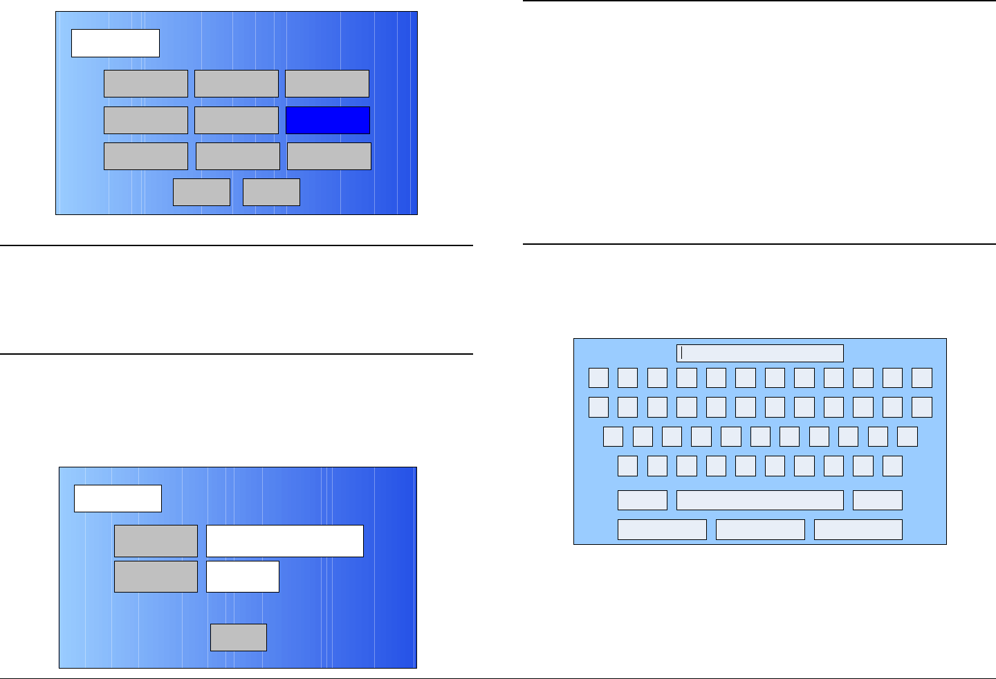
Figure 5-140: Operation Mode Screen
Note When the Save As Preset screen is displayed in
the following step, the Preset Text and Save text
boxes will display the name and identification of the
digital IP Preset currently being used as the digital
IP “make-from” for this custom Preset.
99. Select the Save As Preset option button and observe
the Save As Preset screen is displayed. See
Figure 5-141.
Figure 5-141: Save As Preset Screen - Typical
Operation Mode
Back
COFDM FMT ASI
IP
SCM
LMS-T
Save As Preset
DVBS
MPEG
Main
Save As Preset
Back
Preset Text Digital – DVB-S QPSK
4:2:0,8,3/4,1/8,comp
Save 7
Notes In the following steps, if a factory default digital IP
Preset was used as a “make-from” to prepare this
custom Preset, the Preset Text text box and the
Save text box must be changed. You cannot
change or overwrite any factory default
Presets!
If a custom digital IP Preset was used as a “make-
from” to prepare this custom Preset, a brief
description of the custom Preset must be entered
in the Preset Text text box for easy identification
purposes.
100. Select the Preset Text option button and observe the
keyboard screen is displayed. See Figure 5-142.
Figure 5-142: Keyboard Screen
101. Enter a unique digital IP Preset description, as
required, and select the Enter key.
102. Observe the Save As Preset screen is displayed and
the Preset Text text box displays the Preset
description.
! @ # $ % ^ & * ( ) _ +
Q W E R T Y U I O P { }
A S D F G H J K L :
Z X C V B N M < > ?
Shift BS
Clear CancelEnter
“
Advanced Operations 5-59MTX5000 User and Technical Manual
Notes When saving the new custom digital IP Preset in
the following step, the Preset number will
automatically be increased to the next available
Preset number to avoid overwriting an existing
Preset.
If you wish to overwrite the existing Preset number
(unless it is a factory default Preset), enter the
Preset number to be overwritten. A warning
message will be displayed asking “Are you
sure?”. Select the Yes option button.
Once an existing custom Preset is overwritten, it
cannot be recovered. It must be re-entered from
scratch.
103. Select the Save option button and observe the
numeric keypad is displayed. See Figure 5-143.
Figure 5-143: Numeric Keypad
Notes When saving Presets in the following steps, Preset
A thru Preset J are factory default Presets. The
factory default Preset numbers cannot be changed.
1 2 3
4
7
5 6
8 9
CLR 0ESC
ENT
Next Available
Preset Number
Notes To change the default Preset number, perform step
104 and go to step 105.
To accept the next available Preset number, go to
step 105.
104. Select the CLR key and enter the Preset number
required.
105. Select the ENT key and observe the Are you sure?
confirmation screen is displayed. See Figure 5-144.
Figure 5-144: Confirmation Screen
106. Select the YES option button and observe the Please
Wait! message box is displayed. See Figure 5-145.
Figure 5-145: Please Wait Message Box
107. After a short delay, observe the Save As Preset
screen is displayed.
No
Are you sure?
Yes
No
Please Wait!
Yes

Advanced Operations 5-60MTX5000 User and Technical Manual
108. Select the Main option button and observe the Main
screen is displayed.
5.4.6 Create or Update Digital IP Preset
Configuration Settings in Local Mode
The procedure required to create a new custom digital IP Preset
configuration or to update an existing digital IP Preset
configuration is contained in the following steps.
When preparing a new digital IP Preset, you must first select an
existing digital IP Preset from either the digital IP factory default
Preset or from your own custom digital IP Presets. The selected
Preset will be used as a “make-from” to prepare the new digital
IP Preset configuration.
Please note that while factory default Presets may be used to
prepare a new Preset configuration, these factory default
Presets cannot be changed or deleted. They can only be
used as “make-froms”.
When the new configuration is prepared using the factory default
Preset, it cannot be saved with the factory Preset number or
Preset name. A new Preset number and Preset name must be
assigned to the new Preset.
When using a custom Preset as a “make-from”, the new Preset
should be saved with a new Preset number. When you save the
new Preset, the Preset number will automatically be increased to
the next available Preset number. If you select an existing
Preset number when saving the new Preset, the original custom
Preset will be overwritten and cannot be recovered. The only
way to restore a Preset that has been overwritten is to re-enter
the custom Preset data from scratch.
If you are updating configuration settings on an existing custom
Preset, when you save the configuration settings, the Preset
number will automatically be increased to the next available
Preset number. You must enter and save the configuration
settings using the original Preset number.
Note In the following steps, the color LCD display option
buttons and pull-down menu options may be
selected using either the touch screen or the
function keys and the SEL key.
1. Verify the MTX5000 IDU is powered up. See
”Powering the MTX5000 System” on page 3-7.
2. Observe the Main screen is displayed. See Figure 5-
146.
Figure 5-146: Main Screen - Typical
3. Select the L/R option button for L (local mode), as
required.
Channel 1 0Offset
Antenna Ant. Pol.Antenna1 H
RFU1
No RF
RF Band
Preset A Analog
4.83 & 5.8, 3MHz Vid Dev
RF Output XX
dBm
<- Status Setup Status ->
PA Off
SUM
ODU
IDU
RF
L/R
L
L
PA
Operation
Button
Advanced Operations 5-61MTX5000 User and Technical Manual
Notes If you are updating an existing digital IP Preset
configuration, select the Preset to be updated in
the following step.
If you are creating a new digital IP Preset
configuration, any digital IP Preset may be
selected in the following step.
4. Perform “Select Preset” on page 3-24 to select the
digital IP Preset required to be updated or to be used
as a “make-from”.
5. Select the Main screen PA operation button for PA
Off, as required.
6. Select the Main screen Setup option button and
observe the Setup screen is displayed. See Figure 5-
147.
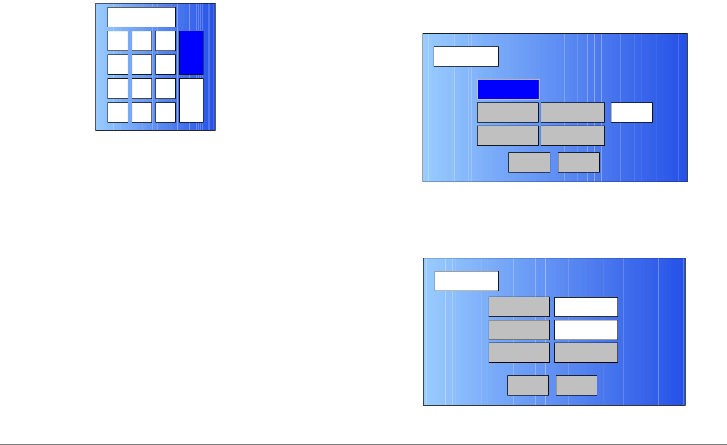
Figure 5-147: Setup Screen
7. Select the User option button and observe the
keyboard screen is displayed. See Figure 5-148.
Setup
User
Main
Radio
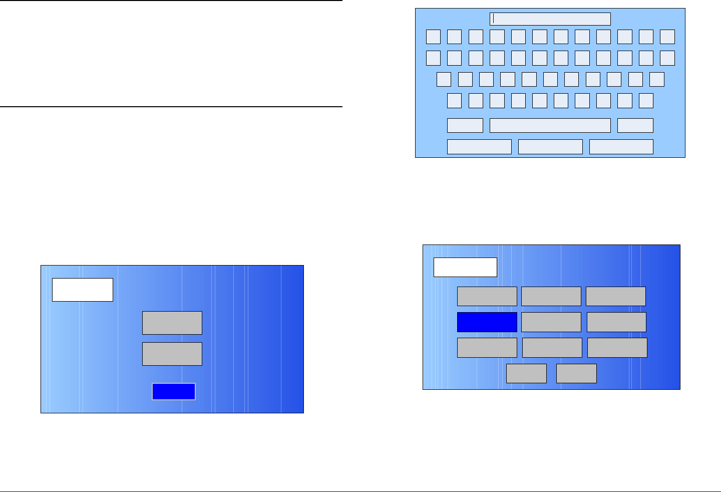
Figure 5-148: Keyboard Screen
8. Enter your password, select the Enter key, and
observe the Operation Mode screen is displayed.
See Figure 5-149.
Figure 5-149: Operation Mode Screen
9. Select the IP option button and observe the IP Config
screen is displayed. See Figure 5-150 on page 5-62.
! @ # $ % ^ & * ( ) _ +
Q W E R T Y U I O P { }
A S D F G H J K L :
Z X C V B N M < > ?
Shift BS
Clear CancelEnter
“
Operation Mode
Back
COFDM FMT ASI
IP
SCM
LMS-T
Save As Preset
DVBS
MPEG
Main
Advanced Operations 5-62MTX5000 User and Technical Manual
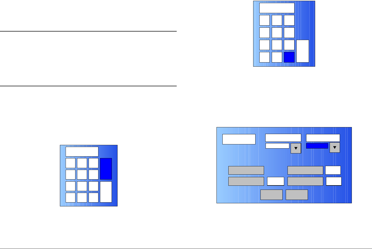
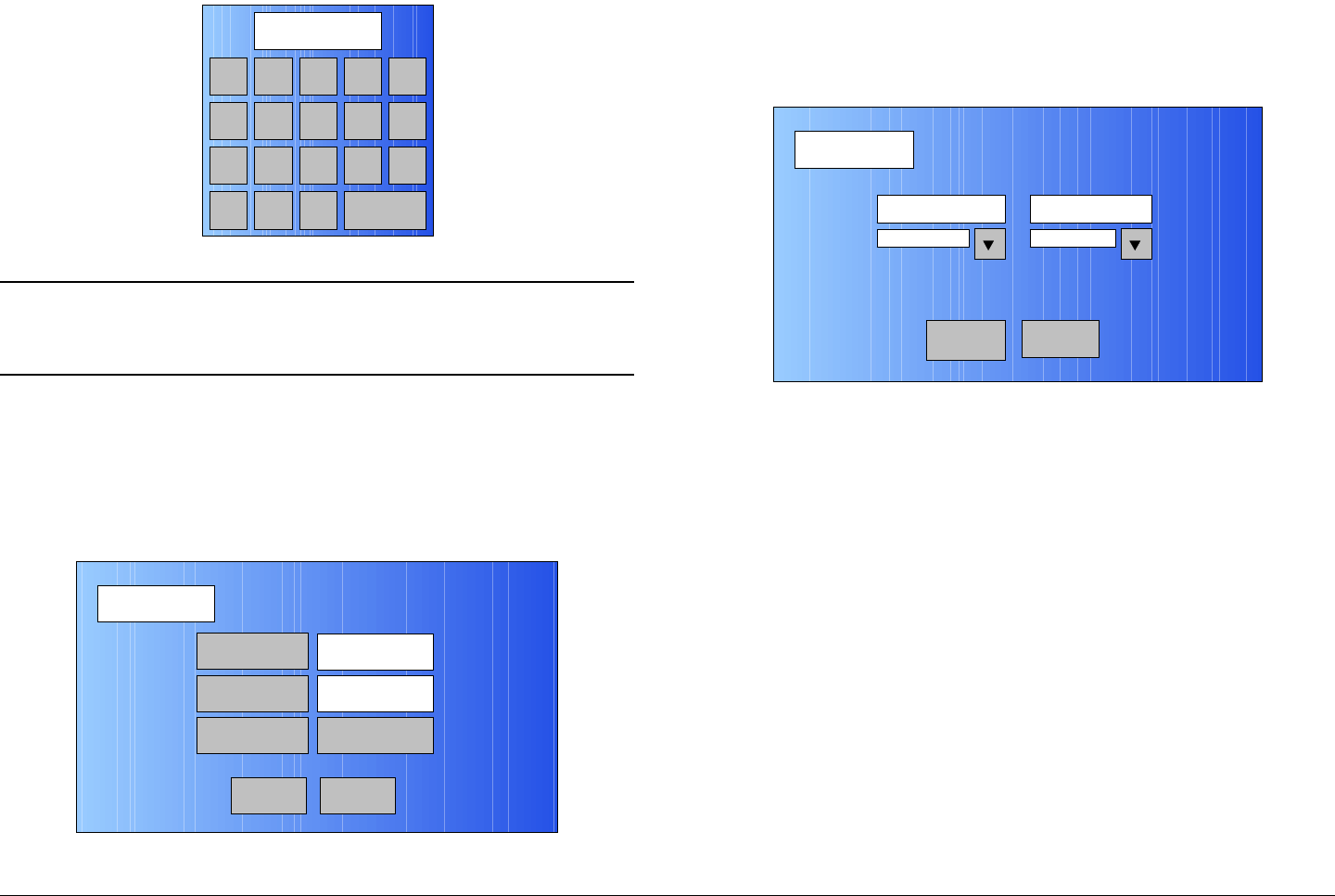
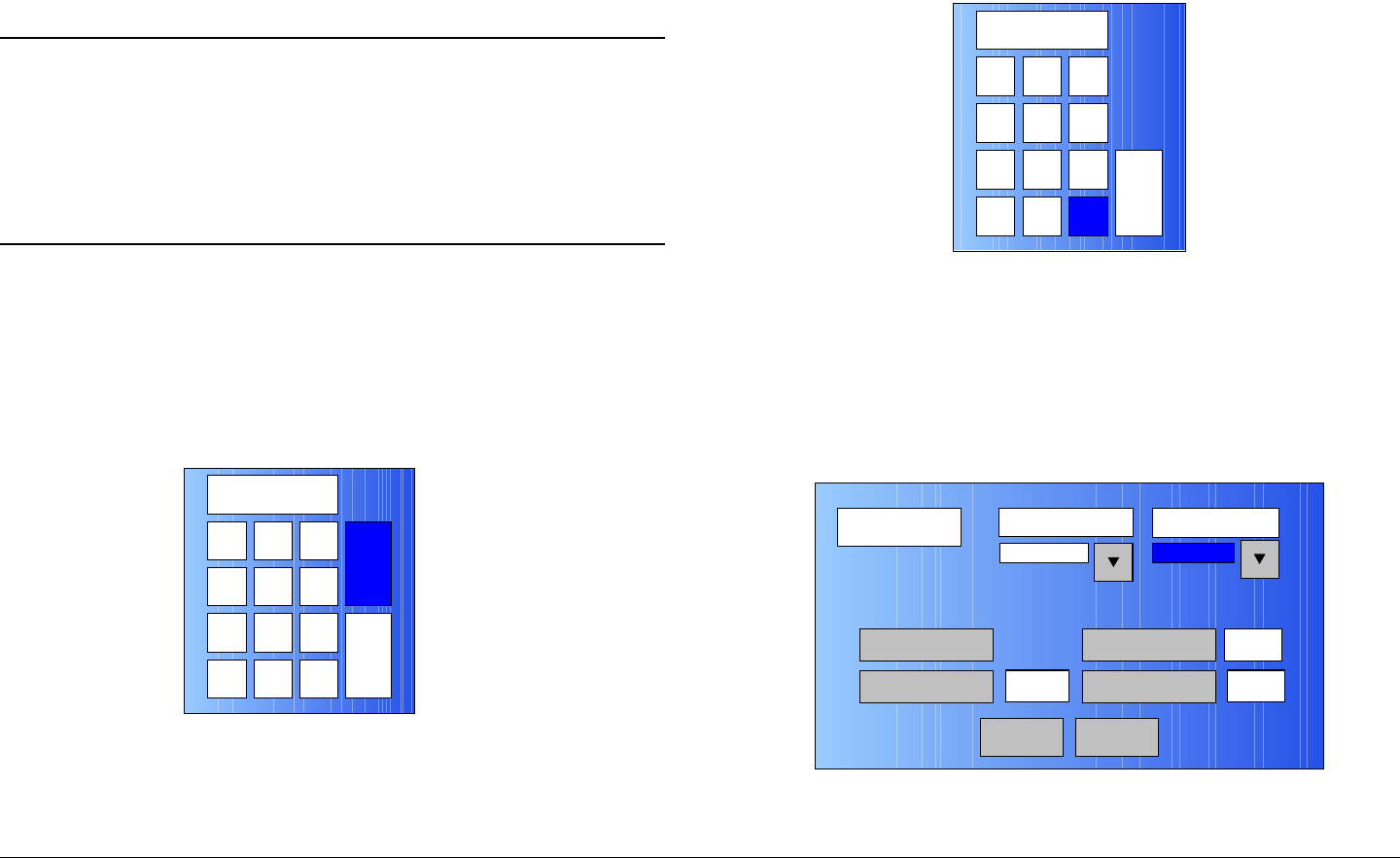
Figure 5-150: IP Config Screen - Typical
10. Use the FEC pull-down menu to select 1/2. 2/3, 3/4,
5/6, or 7/8, as required
11. Use the Guard Interval pull-down menu and select
1/32, 1/16, 1/4, or 1/8, as required.
12. Use the Constellation pull-down menu to select
QPSK, 16-QAM, or 64-QAM, as required.
13. Use the RF B/W pull-down menu to select 6 MHZ,
7 MHZ, or 8 MHZ, as required.
14. Select the Next option button and observe the IP
Setup screen is displayed. See Figure 5-151.
IP Config
Back
FEC Guard Interval Constellation
1/8
RF B/W
1/2 QPSK
8 MHz
NextMain
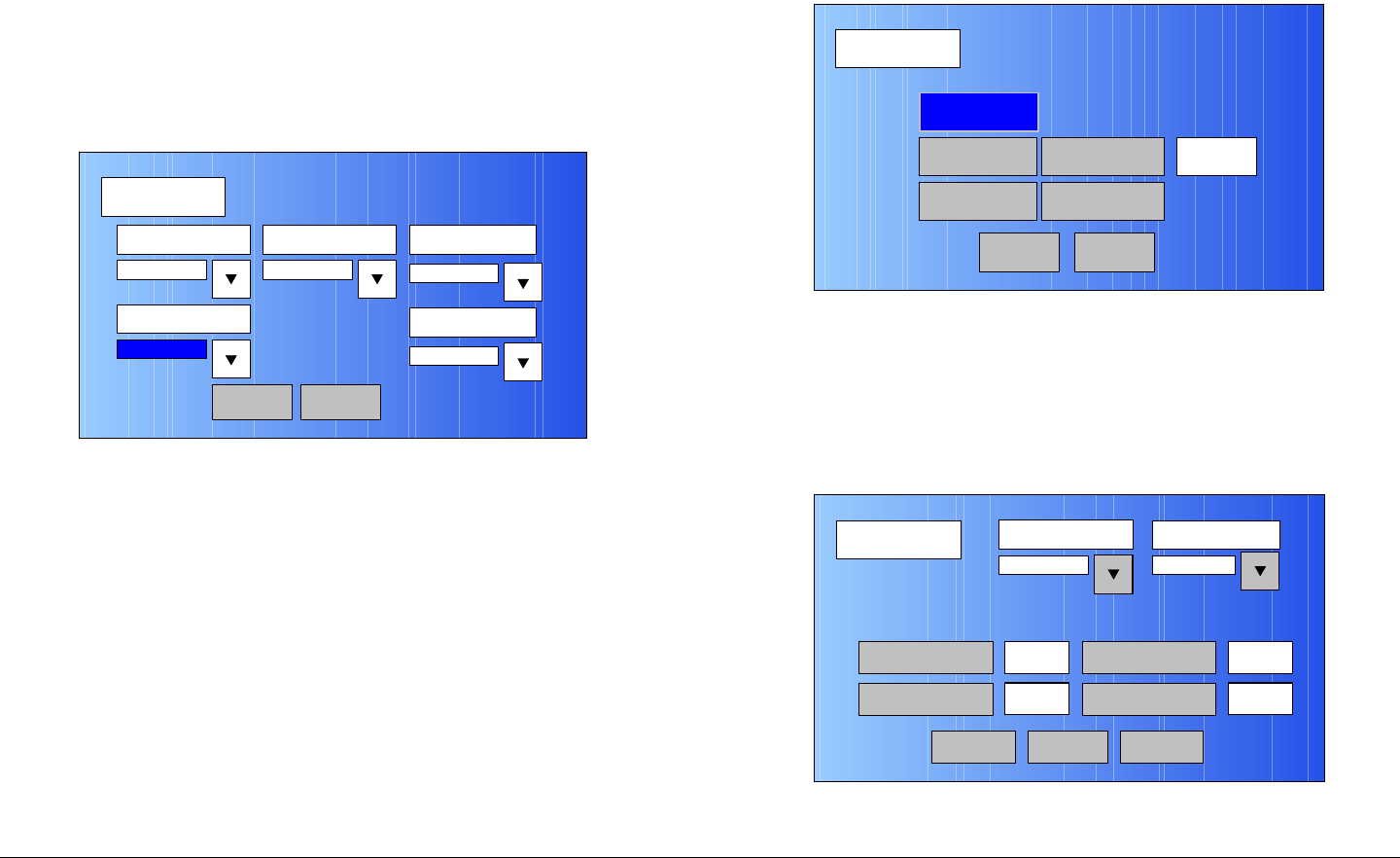
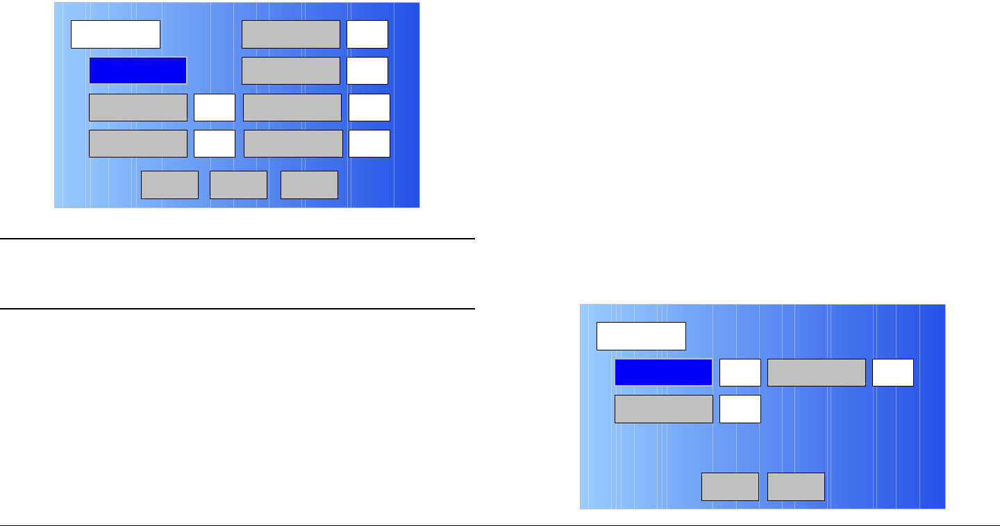
Figure 5-151: IP Setup Screen - Typical
Notes If the IP + Video option is selected in the following
step, go to step 16.
The Video Bitrate option button is active only if the
IP + Video option is selected.
If the IP Only option is selected in the following
step, go to step 20.
15. Use the IP Transfer Mode pull-down menu to select
IP Only or IP + Video, as required, and select the
Submit option button.
16. Observe the Video Bitrate option button is active.
17. Select the Video Bitrate option button and observe
the numeric keypad is displayed. See Figure 5-152 on
page 5-63.
IP Setup
Submit
IP Transfer Mode
Max Bit Rate 19.350 Mbps
12.902 Mbps
IP + Video
Main
Video Bitrate
IP Rate
5.2 Mbps Back
Advanced Operations 5-63MTX5000 User and Technical Manual
Figure 5-152: Numeric Keypad
CAUTION When entering the video bit rate in the
following step, the bit rate value entered
cannot exceed the IP Setup screen Max Bit
Rate value minus 1.22 Mbps. Exceeding
the Max Bit Rate value minus 1.22 Mbps
will result in no video output.
For example, a Max Bit Rate value of
19.350 Mbps - 1.22 Mbps = 18.130 Mbps.
Therefore, the video bit rate entered in the
following step must not exceed 18.130
Mbps.
18. Enter the video bit rate required and select the ENT
option button.
19. Select the Submit option button.
20. Select the Back option button and observe the IP
Config screen is displayed.
21. Select the Back option button and observe the
Operation Mode screen is displayed. See Figure 5-
153.
123
ESC
0
4
7
5 6
8 9
DEL 0ESC
ENT
Figure 5-153: Operation Mode Screen
22. Select the MPEG option button and observe the
MPEG screen is displayed. See Figure 5-154.
Figure 5-154: MPEG Screen - Typical
23. Select the Video In option button and observe the
Video In screen is displayed. See Figure 5-155 on
page 5-64.
Operation Mode
Back
COFDM FMT ASI
IP
SCM
LMS-T
Save As Preset
DVBS
MPEG
Main
MPEG
Back
Video In
Audio In
Encoder
NormalSpectrum Invert
Encoding
Main
Advanced Operations 5-64MTX5000 User and Technical Manual
Figure 5-155: Video In Screen 1 - Typical
Note In the following step, select an Input option
applicable to the licensed options contained in your
MTX5000 IDU only. Selection of an option that is
not licensed in your radio will cause the IDU to
operate in the NTSC default mode.
24. Use the Input pull-down menu to select the video
input option required.
25. Select the Video In2 option button and observe the
Video In screen 2 is displayed. See Figure 5-156.
Video In
Back
Input
NTSC
Video In2
Figure 5-156: Video In Screen 2 - Typical
26. Select the Noise Reduction option button for On or
Off, as required.
27. Select the SDI Auto Line option button for On or Off,
as required.
28. Select the HD Test Pattern option button for On or
Off, as required.
29. Select the Back option button and observe the Video
In screen is displayed.
30. Select the Back option button and observe the MPEG
screen is displayed. See Figure 5-157 on page 5-65.
Video In
Back
Noise Reduction
SDI Auto Line
Off
Off HD Test Pattern Off
Main
Advanced Operations 5-65MTX5000 User and Technical Manual
Figure 5-157: MPEG Screen - Typical
31. Select the Audio In option button and observe the
AUDIO 1 screen is displayed. See Figure 5-158.
Figure 5-158: AUDIO 1 Screen - Typical
32. Use the Mode pull-down menu to select Stereo or
Dual Mono, as required.
33. Use the Standard pull-down menu to select Off,
MPEG Layer II, Linear PCM, or MPEG Layer I, as
required.
MPEG
Back
Video In
Audio In
Encoder
NormalSpectrum Invert
Encoding
Main
AUDIO 1
Back
Mode Standard Bit Rate
MPEG Layer II
Input
Dual Mono 192 Kbps
Analog
Audio 2Main
34. Use the Bit Rate pull-down menu to select 128 Kbps,
160 Kbps, 192 Kbps, 224 Kbps, 256 Kbps, 320
Kbps, or 384 Kbps, as required.
35. Use the Input pull-down menu to select Test Tone,
Analog, or SDI Emb, as required.
36. Select the Audio 2 option button and observe the
AUDIO 2 screen is displayed. See Figure 5-159.
Figure 5-159: AUDIO 2 Screen - Typical
37. Use the Mode pull-down menu to select Stereo or
Dual Mono, as required.
38. Use the Standard pull-down menu to select Off,
MPEG Layer II, Linear PCM, or MPEG Layer I, as
required.
39. Use the Bit Rate pull-down menu to select 128 Kbps,
160 Kbps, 192 Kbps, 224 Kbps, 256 Kbps, 320
Kbps, or 384 Kbps, as required.
40. Use the Input pull-down menu to select Test Tone,
Analog, SDI Emb, AES-EBU, or Channel Ide, as
required.
41. Use the Balance pull-down menu to select
Unbalanced or Balanced, as required.
AUDIO 2
Back
Mode Standard Bit Rate
MPEG Layer II
Input
Dual Mono 192 Kbps
Analog
Main
Balance
Unbalanced
Advanced Operations 5-66MTX5000 User and Technical Manual
42. Select the Back option button and observe the AUDIO
1 screen is displayed.
43. Select the Back option button and observe the MPEG
screen is displayed. See Figure 5-160.
Figure 5-160: MPEG Screen - Typical
44. Select the Spectrum Invert option button to select
Normal or Inverted, as required.
45. Select the Encoder option button and observe the
Encoder screen is displayed. See Figure 5-161.
Figure 5-161: Encoder Screen - Typical
MPEG
Back
Video In
Audio In
Encoder
NormalSpectrum Invert
Encoding
Main
Encoder
Back
Mode Bit Rate
Low delay
4.9 Mb/s
Bit Rate
On
MP@ML
Encoder 2
Bit Rate Auto GOP Length 15
Main
ASI Bit Rate 5.529
Mb/s
46. Select the Mode pull-down menu and select Standard
or Low delay, as required.
47. Select the Bit Rate pull-down menu and select
MP@ML or 422P@ML, as required.
Notes In the following step, if the Bit Rate Auto option
button On option is selected, the Bit Rate option
button will be inactive (greyed out). Go to step 50.
If the Bit Rate Auto option button Off option is
selected, the Bit Rate option button will be active.
Go to step 49.
48. Select the Bit Rate Auto option button for Off or On,
as required.
49. Observe the Bit Rate option button is active. Select
the Bit Rate option button and observe the numeric
keypad is displayed. See Figure 5-162.
Figure 5-162: Numeric Keypad
50. Enter the bit rate required, select the ENT key, and
observe the Encoder screen is displayed.
123
ESC
0
4
7
5 6
8 9
DEL 0ESC
ENT
Advanced Operations 5-67MTX5000 User and Technical Manual
51. Select the GOP Length option button and observe the
numeric keypad is displayed. See Figure 5-163.
Figure 5-163: Numeric Keypad
52. Enter the Group of Pictures (GOP) number required,
select the ENT key, and observe the Encoder screen
is displayed.
53. Select the Encoder 2 option button and observe the
Encoder screen is displayed. See Figure 5-164.
Figure 5-164: Encoder Screen 2 - Typical
54. Select the Horiz Resolution pull-down menu and
select 720, 704, 544, 528, 480, or 352, as required.
123
4
7
5 6
8 9
CLR 0ESC
ENT
Encoder
Back
Horiz Resolution Aspect Ratio
720
PID
Off
4:3
PTS per Picture VBI Off
Main
Remux Off
55. Select the Aspect Ratio pull-down menu and select
4:3 or 16:9, as required.
56. Select the PID option button and observe the PID
screen is displayed. See Figure 5-165.
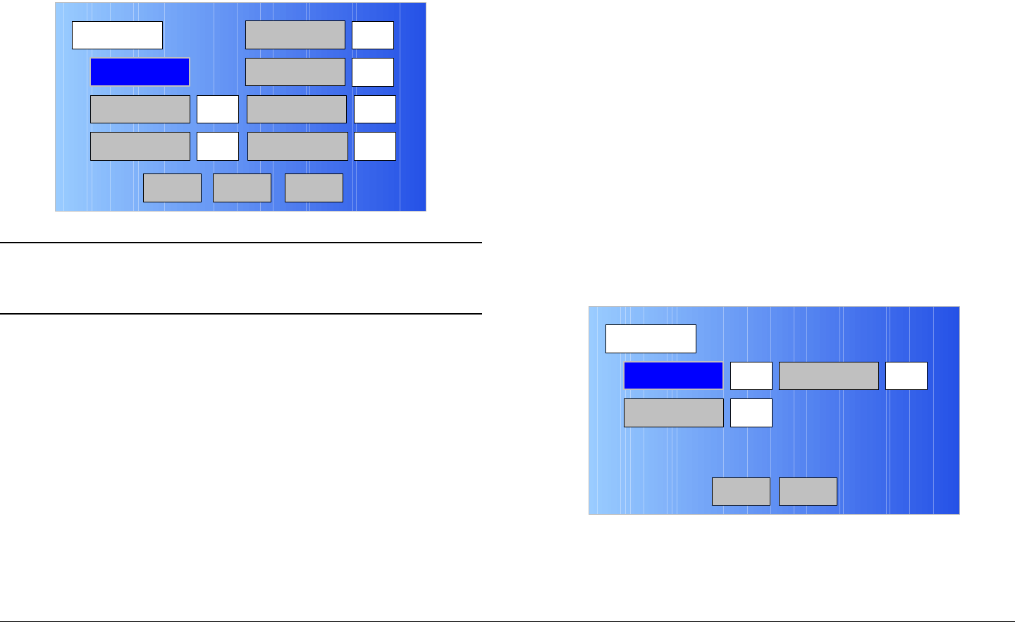
Figure 5-165: PID Screen - Typical
Notes To select the default PID settings, go to step 57.
To enter individual PID settings, go to step 58.
57. Select the DEFAULT option button and observe the
default PID settings are displayed. Go to step 78.
58. Select the DATA option button and observe the
numeric keypad is displayed.
59. Enter the DATA PID required, select the ENT key, and
observe the PID screen is displayed.
60. Select the AUDIO A option button and observe the
numeric keypad is displayed.
61. Enter the AUDIO A PID required, select the ENT key,
and observe the PID screen is displayed.
PID
Main
DEFAULT
PMT
300
12 AUDIO B 201
DATA
AUDIO A
100
200
VIDEO PCR 8190
Back Next

Advanced Operations 5-68MTX5000 User and Technical Manual
62. Select the PMT option button and observe the numeric
keypad is displayed.
63. Enter the PMT PID required, select the ENT key, and
observe the PID screen is displayed.
64. Select the AUDIO B option button and observe the
numeric keypad is displayed.
65. Enter the AUDIO B PID required, select the ENT key,
and observe the PID screen is displayed.
66. Select the VIDEO option button and observe the
numeric keypad is displayed.
67. Enter the Video PID required, select the ENT key, and
observe the PID screen is displayed.
68. Select the PCR option button and observe the numeric
keypad is displayed.
69. Enter the PCR PID required, select the ENT key, and
observe the PID screen is displayed.
70. Select the Next option button and observe the PID-2
screen is displayed. See Figure 5-166.
Figure 5-166: PID-2 Screen - Typical
71. Select the Program ID option button and observe the
numeric keypad is displayed. See Figure 5-167.
PID-2
Main
Program ID
Transport ID 1
Network ID3 1
Back
Figure 5-167: Numeric Keypad
72. Enter the Program ID PID required, select the ENT
key, and observe the PID-2 screen is displayed.
73. Select the Network ID option button and observe the
numeric keypad is displayed.
74. Enter the Network ID PID required, select the ENT
key, and observe the PID-2 screen is displayed.
75. Select the Transport ID option button and observe the
numeric keypad is displayed.
76. Enter the Transport ID PID required, select the ENT
key, and observe the PID-2 screen is displayed.
77. Select the Back option button and observe the PID
screen is displayed.
78. Select the Back option button and observe the
Encoder screen is displayed.
79. Select the Remux option button for On or Off, as
required.
80. Select the PTS per Picture option button to select On
or Off, as required.
81. Select the VBI option button for On or Off, as required.
82. Select the Back option button and observe the
Encoder screen is displayed.
1 2 3
ESC
0
4
7
5 6
8 9
DEL 0ESC
ENT
Advanced Operations 5-69MTX5000 User and Technical Manual
83. Select the Back option button and observe the MPEG
screen is displayed. See Figure 5-168.
Figure 5-168: MPEG Screen - Typical
84. Select the Encoding option button and observe the
Encoding screen is displayed. See Figure 5-169.
Figure 5-169: Encoding Screen - Typical
85. Select the Service Name option button and observe
the keyboard screen is displayed. See Figure 5-170.
MPEG
Back
Video In
Audio In
Encoder
NormalSpectrum Invert
Encoding
Main
Encoding
Back
Service Name
Network Name
EBS/BISS Wayside data
Service 01
Main
Figure 5-170: Keyboard Screen
86. Enter the service name required, select the Enter key,
and observe the Encoding screen is displayed.
87. Select the Network Name option button and observe
the keyboard screen is displayed.
88. Enter the network name required, select the Enter
key, and observe the Encoding screen is displayed.
Notes If your MTX5000 IDU contains a licensed EBS or
BISS encryption option, go to step 89.
If your MTX5000 IDU does not contain a licensed
EBS or BISS encryption option, go to step 95.
89. Observe the EBS/BISS option button is active (not
greyed-out).
90. Select the EBS/BISS option button and observe the
Encryption screen is displayed. See Figure 5-171 on
page 5-70.
! @ # $ % ^ & * ( ) _ +
Q W E R T Y U I O P { }
A S D F G H J K L :
Z X C V B N M < > ?
Shift BS
Clear CancelEnter
“
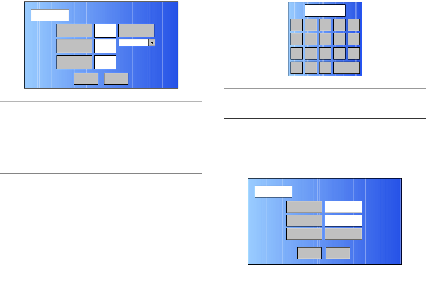
Advanced Operations 5-70MTX5000 User and Technical Manual
Figure 5-171: Encryption Screen
Notes You can only have one licensed encryption option
contained in your MTX5000 IDU.
When the Scrambling pull-down menu EBS,
BISS-1, or BISS-E option is selected in the
following step, the selected option key will be
active, but the two remaining option buttons will
become inactive (greyed-out).
91. Select the Scrambling pull-down menu EBS, BISS-1,
or BISS-E option, as required, and observe the
selected EBS, BISS-1, or BISS-E Key option button is
active.
92. Select the EBS, BISS-1, or BISS-E Key option button,
as required, and observe the alphanumeric keypad is
displayed. See Figure 5-172.
Encryption
Back
EBS Key
BISS-1 Key
BISS-E Key
xx Scrambling
xx
xx
Main
Figure 5-172: Alphanumeric Keypad
Note When the Encryption screen is displayed and the
encryption key is entered in the following step, the
encryption key will not be displayed.
93. Enter your encryption key, select the ENT key, and
observe the Encryption screen is displayed.
94. Select the Back option button and observe the
Encoding screen is displayed. See Figure 5-173.
Figure 5-173: Encoding Screen - Typical
1 2 3
0
4
7
5 6
8 9
DEL CAN 0ENT
A D
B E
C F
Encoding
Back
Service Name
Network Name
EBS/BISS Wayside data
Service 01
Main
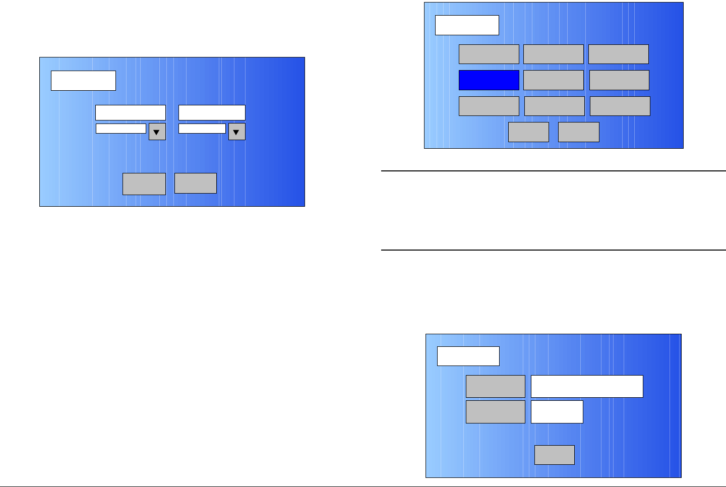
Advanced Operations 5-71MTX5000 User and Technical Manual
95. Select the Wayside data option button and observe
the Wayside Data screen is displayed. See Figure 5-
174.
Figure 5-174: Wayside Data Screen - Typical
96. Select the Data Enable pull-down menu and select
the Off, TTV Format, CJM2 Format, or Low Delay
CJM2 option, as required.
97. Select the Baud Rate pull-down menu and select the
1200, 2400, 4800, 9600, 19200, or 38400 option, as
required.
98. Select the Back option button and observe the
Encoding screen is displayed.
99. Select the Back option button and observe the MPEG
screen is displayed.
100. Select the Back option button and observe the
Operation Mode screen is displayed. See Figure 5-
175.
Wayside Data
Back
Data Enable Baud Rate
Off 2400
Main
Figure 5-175: Operation Mode Screen
Note When the Save As Preset screen is displayed in
the following step, the Preset Text and Save text
boxes will display the name and identification of the
digital IP Preset currently being used as the digital
IP “make-from” for this custom Preset.
101. Select the Save As Preset option button and observe
the Save As Preset screen is displayed. See
Figure 5-176.
Figure 5-176: Save As Preset Screen - Typical
Operation Mode
Back
COFDM FMT ASI
IP
SCM
LMS-T
Save As Preset
DVBS
MPEG
Main
Save As Preset
Back
Preset Text Digital – IP 16QAM
4:2:0,8,7/8,1/8
Save 9
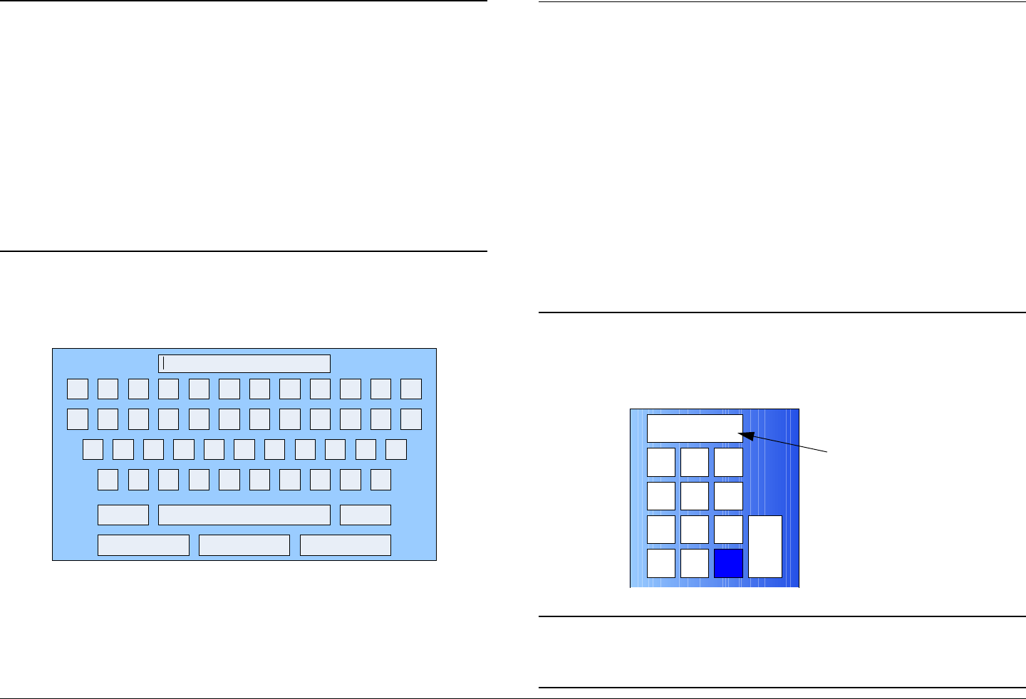
Advanced Operations 5-72MTX5000 User and Technical Manual
Notes In the following steps, if a factory default digital IP
Preset was used as a “make-from” to prepare this
custom Preset, the Preset Text text box and the
Save text box must be changed. You cannot
change or overwrite any factory default
Presets!
If a custom digital IP Preset was used as a “make-
from” to prepare this custom Preset, a brief
description of the custom Preset must be entered
in the Preset Text text box for easy identification
purposes.
102. Select the Preset Text option button and observe the
keyboard screen is displayed. See Figure 5-177.
Figure 5-177: Keyboard Screen
103. Enter a unique digital IP Preset description, as
required, and select the Enter key.
104. Observe the Save As Preset screen is displayed and
the Preset Text text box displays the Preset
description.
! @ # $ % ^ & * ( ) _ +
Q W E R T Y U I O P { }
A S D F G H J K L :
Z X C V B N M < > ?
Shift BS
Clear CancelEnter
“
Notes When saving the new custom digital IP Preset in
the following step, the Preset number will
automatically be increased to the next available
Preset number to avoid overwriting an existing
Preset.
If you wish to overwrite the existing Preset number
(unless it is a factory default Preset), enter the
Preset number to be overwritten. A warning
message will be displayed asking “Are you
sure?”. Select the Yes option button.
Once an existing custom Preset is overwritten, it
cannot be recovered. It must be re-entered from
scratch.
105. Select the Save option button and observe the
numeric keypad is displayed. See Figure 5-178.
Figure 5-178: Numeric Keypad
Notes When saving Presets in the following steps, Preset
A thru Preset J are factory default Presets. The
factory default Preset numbers cannot be changed.
1 2 3
4
7
5 6
8 9
CLR 0ESC
ENT
Next Available
Preset Number

Advanced Operations 5-73MTX5000 User and Technical Manual
Notes To change the default Preset number, perform step
106 and go to step 107.
To accept the next available Preset number, go to
step 107.
106. Select the CLR key and enter the Preset number
required.
107. Select the ENT key and observe the Are you sure?
confirmation screen is displayed. See Figure 5-179.
Figure 5-179: Confirmation Screen
108. Select the YES option button and observe the Please
Wait! message box is displayed. See Figure 5-180.
Figure 5-180: Please Wait Message Box
No
Are you sure?
Yes
No
Please Wait!
Yes
109. After a short delay, observe the Save As Preset
screen is displayed.
110. Select the Main option button and observe the Main
screen is displayed.
5.5 Create or Update Preset
Configuration Settings in Remote Mode
The procedures required to create or update Preset
configuration settings in the Remote mode using a remote PC
are contained in the following paragraphs. Preset configuration
settings may be created or updated for the following types of
Presets:
• Analog FMT Presets
• Digital COFDM Presets
• Digital ASI Presets
• Digital LMS-T Presets
• Digital DVB-S Presets
• Digital IP Presets.
Please note that an External IF In Preset is available for
normal operation using the factory default External IF In
Preset, but no configuration settings may be made to this
Preset. No procedures are therefore applicable or are provided
for External IF In Presets.
5.5.1 Create or Update Custom Analog Preset
Configuration in Remote Mode
The procedure required to create a new custom user analog
Preset configuration or to update an existing user Preset
configuration in the Remote mode is contained in the following
steps.
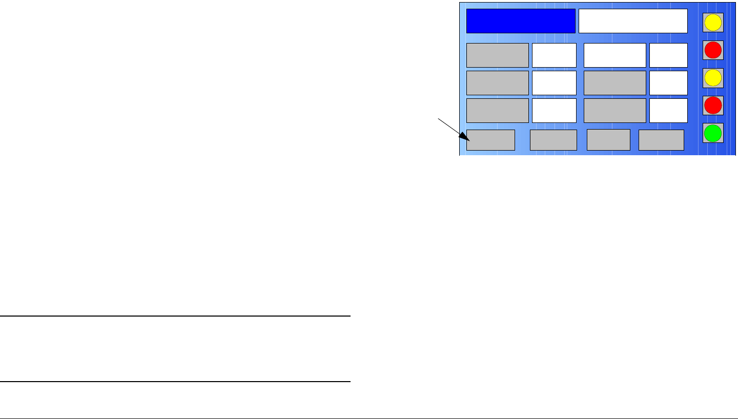
Advanced Operations 5-74MTX5000 User and Technical Manual
When preparing a new analog Preset, you must first select an
existing analog Preset from either one of the analog factory
default Presets or from your custom user analog Presets. The
selected Preset will be used as a “make-from” to prepare the
new user analog Preset configuration.
Please note that while factory default analog Presets may be
used to prepare a new Preset configuration, these factory
default Presets cannot be changed or deleted. They can only
be used as “make-froms”.
When the new configuration is prepared using the factory default
Preset, it cannot be saved with the factory Preset number or
Preset name. A new Preset number and Preset name must be
assigned to the new Preset.
When using a custom user Preset as a “make-from”, the new
Preset should be saved with a new Preset number.
If you select an existing user Preset number when saving the
new Preset, the original custom Preset will be overwritten and
cannot be recovered. The only way to restore a Preset that has
been overwritten is to re-enter the custom Preset data from
scratch.
If you are updating configuration settings on an existing custom
user Preset, when you save the configuration settings, the
Preset number will automatically be increased to the next
available Preset number. You must enter and save the
configuration settings using the original Preset number.
Note In the following steps, the color LCD display option
buttons and pull-down menu options may be
selected using either the touch screen or the
function keys and the SEL key.
1. Verify the MTX5000 IDU is powered up. See
”Powering the MTX5000 System” on page 3-7.
2. Observe the Main screen is displayed. See Figure 5-
181.
Figure 5-181: Main Screen - Typical
3. Select the L/R option button for L (Local), as required.
4. Select the PA operation button for PA Off, as required
5. Select the Setup option button and observe the Setup
screen is displayed.
6. Select the Radio option button and observe the Radio
screen is displayed.
7. Select the Next option button and observe the Radio -
2 screen is displayed.
8. Select the Remote Ctrl Option button and observe
the Select Remote Ctrl Opt screen is displayed.
9. Select the Remote option button and observe the
Radio - 2 screen is displayed.
10. Select the Main option button, observe the Main
screen is displayed, and observe the L/R option button
indicates R (Remote).
Channel 1 0Offset
Antenna Ant. Pol.Antenna1 H
RFU1
No RF
RF Band
Preset A Analog
4.83 & 5.8, 3MHz Vid Dev
RF Output XX
dBm
<- Status Setup Status ->
PA Off
SUM
ODU
IDU
RF
L/R
L
L
PA
Operation
Button
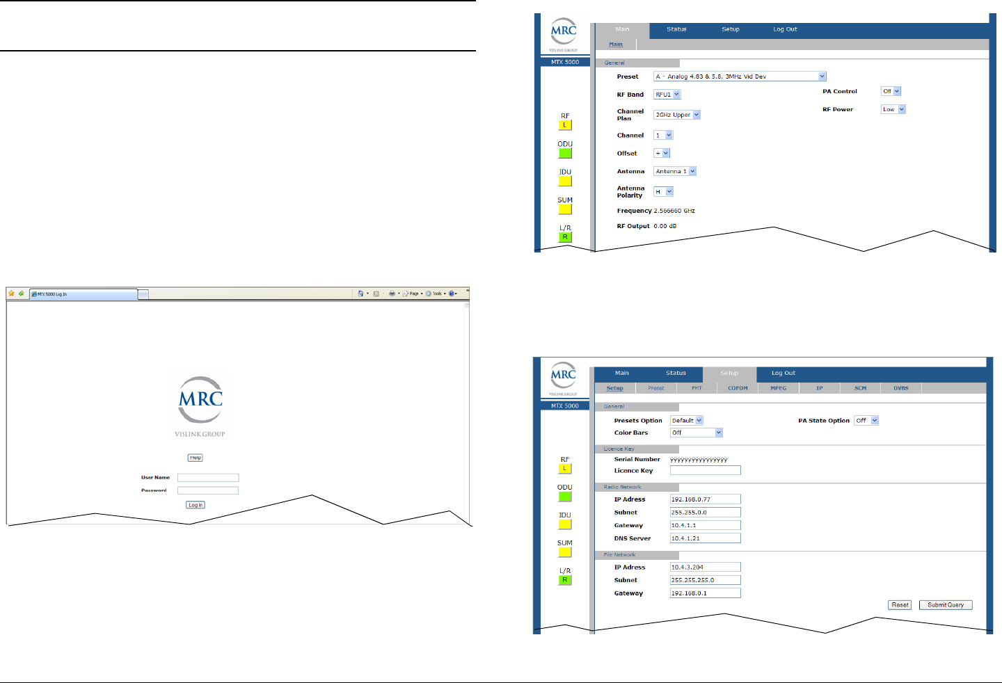
Advanced Operations 5-75MTX5000 User and Technical Manual
Note In the following step, XXX.XXX.X.XX is the IP
address of your MTX5000 IDU.
11. At the remote PC, open your web browser, enter the IP
address for your MTX5000 IDU, and press the
keyboard Enter key. The IP address should be
entered as follows:
http://XXX.XXX.X.XX/nfs/main/html
12. After a short delay, observe the remote log in screen is
displayed. See Figure 5-182.
Figure 5-182: Remote Log In Screen - Typical
13. Enter your administrator user name in the User Name
text box, enter your administrator password in the
Password text box, select the Log In option button,
and observe the MTX50000 Main Page is displayed.
See Figure 5-183.
Figure 5-183: MTX5000 Main Page - Typical
14. Select the Setup tab and observe the Setup page is
displayed by default. See Figure 5-184.
Figure 5-184: Setup Tab - Typical

Advanced Operations 5-76MTX5000 User and Technical Manual
Note In the following step, if a factory default analog
Preset is to be used to prepare a new Preset
configuration, select the Default option.
If a custom user Preset is to be updated or is to be
used to prepare a new Preset, select the User
option.
15. Use the Presets Option pull-down menu and select
Default or User, as required.
16. Use the Color Bars pull-down menu and select Off,
On, Auto Gen, or Auto Standby, as required.
17. Use the PA State Option pull-down menu to select
Off or Last, as required.
18. Select the Submit option button.
19. Select the Main tab and observe the Main page is
displayed.
20. Use the Preset pull-down menu to select the default or
user custom analog Preset required.
21. Select the Setup tab and observe the Setup page is
displayed.
22. Select the FMT tab and observe the FMT page is
displayed.
23. Use the Video Deviation pull-down menu to select 3
MHz or 4 MHz, as required.
24. Use the Video Input pull-down menu to select
Composite or Baseband, as required.
Note Repeat step 25 thru step 27 for Audio CH1 thru
Audio CH4, as required.
25. Use the Enable pull-down menu to select On or Off,
as required.
26. Use the Pre-Emphasis pull-down menu to select On
or Off, as required.
Note In the following step, the Frequency pull-down
menus have 11 frequency options and a Custom
option.
If the Custom option is selected, a frequency text
box will be displayed adjacent to the pull-down
menu.
27. Use the Frequency pull-down menu to select the
frequency option required or select Custom.
If Custom is selected, enter the frequency required in
the active text box(es), as required. Frequency range
is 4830 to 8590 kHz.
28. When Audio CH1 thru Audio CH4 options have all
been selected, select the Submit option button.
29. Select the Preset tab and observe the Preset page is
displayed.

Advanced Operations 5-77MTX5000 User and Technical Manual
Notes In the following steps, if a factory Default analog
Preset was used as a “make-from” to prepare this
custom Preset, the Preset Text text box and the
Preset Number text box must be changed. You
cannot change or overwrite any factory default
Presets!
If a custom User analog Preset was used as a
“make-from” to prepare this custom Preset, a brief
description of the custom Preset should be entered
in the Preset Text text box for easy identification
purposes. The Preset number must be changed
only if you do not wish to overwrite the custom
Preset.
30. Select the Preset Text text box and enter a unique
analog Preset description.
Note If you used a factory Default Preset or a custom
User Preset as a “make-from” and you want to add
the new Preset to the list of User Presets
contained in your MTX5000 IDU, you must know
the highest user Preset number contained in your
IDU. To add the new Preset to the list of User
Presets, go to step 31.
If you used a custom User Preset as a “make-
from” and you want to use it to replace (overwrite)
an existing custom User Preset, go to step 33.
31. Select the Preset Number text box and enter any
Preset number that is higher than the current highest
user Preset number in your MTX5000 IDU.
32. Select the Submit option button and observe that the
Preset Number automatically displays the next higher
Preset number available in the Preset User list. Go to
step 34.
33. Select the Preset Number text box, enter the Preset
number that you wish to overwrite, and select the
Submit option button.
34. Observe the new Preset configuration has been
loaded into the MTX5000 IDU and the new Preset
name and Preset number are displayed on the Main
page.
5.5.2 Create or Update Custom Digital COFDM
Preset Configuration in Remote Mode
The procedure required to create a new custom digital COFDM
Preset configuration or to update an existing Preset configuration
in the Remote mode is contained in the following steps.
When preparing a new user digital COFDM Preset, you must first
select an existing digital COFDM Preset from either one of the
digital COFDM factory default Presets or from your own custom
digital COFDM Presets. The selected Preset will be used as a
“make-from” to prepare the new digital COFDM Preset
configuration.
Please note that while factory default digital COFDM Presets
may be used to prepare a new Preset configuration, these
factory default Presets cannot be changed or deleted. They
can only be used as “make-froms”.
When the new configuration is prepared using the factory default
Preset, it cannot be saved with the factory Preset number or
Preset name. A new Preset number and Preset name must be
assigned to the new Preset.
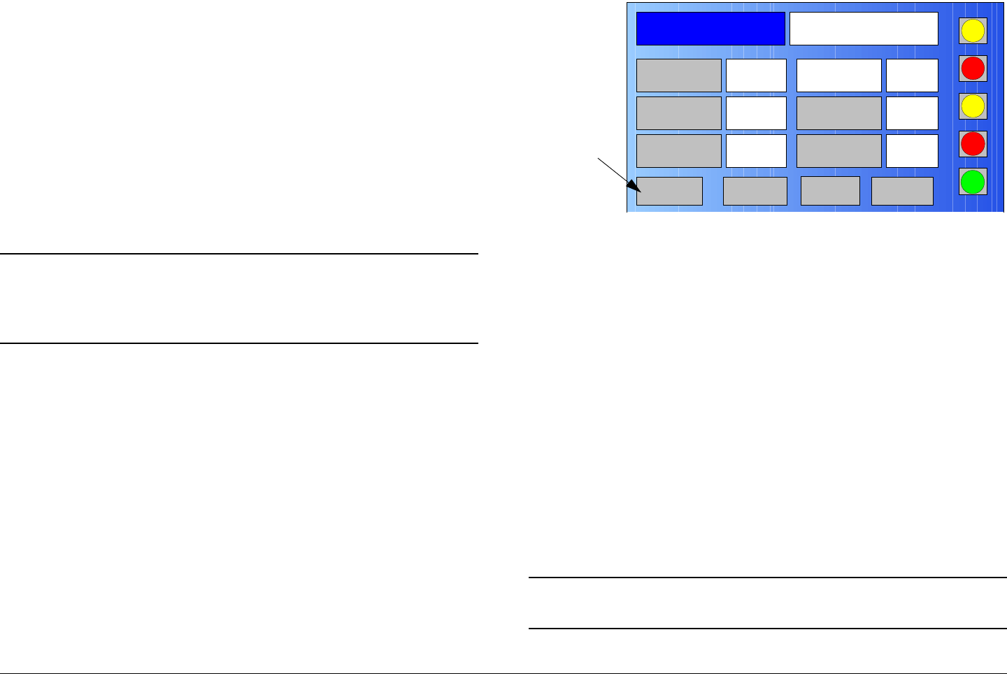
Advanced Operations 5-78MTX5000 User and Technical Manual
When using a custom user Preset as a “make-from”, the new
Preset should be saved with a new Preset number.
If you select an existing user Preset number when saving the
new Preset, the original custom Preset will be overwritten and
cannot be recovered. The only way to restore a Preset that has
been overwritten is to re-enter the custom Preset data from
scratch.
If you are updating configuration settings on an existing custom
Preset, when you save the configuration settings, the Preset
number will automatically be increased to the next available
Preset number. You must enter and save the configuration
settings using the original Preset number.
Note In the following steps, the color LCD display option
buttons and pull-down menu options may be
selected using either the touch screen or the
function keys and the SEL key.
1. Verify the MTX5000 IDU is powered up. See
”Powering the MTX5000 System” on page 3-7.
2. Observe the Main screen is displayed. See Figure 5-
185.
Figure 5-185: Main Screen - Typical
3. Select the L/R option button for L (Local), as required.
4. Select the PA operation button for PA Off, as required
5. Select the Setup option button and observe the Setup
screen is displayed.
6. Select the Radio option button and observe the Radio
screen is displayed.
7. Select the Next option button and observe the Radio -
2 screen is displayed.
8. Select the Remote Ctrl Option button and observe
the Select Remote Ctrl Opt screen is displayed.
9. Select the Remote option button and observe the
Radio - 2 screen is displayed.
10. Select the Main option button, observe the Main
screen is displayed, and observe the L/R option button
indicates R (Remote).
Note In the following step, XXX.XXX.X.XX is the IP
address of your MTX5000 IDU.
Channel 1 0Offset
Antenna Ant. Pol.Antenna1 H
RFU1
No RF
RF Band
Preset A Analog
4.83 & 5.8, 3MHz Vid Dev
RF Output XX
dBm
<- Status Setup Status ->
PA Off
SUM
ODU
IDU
RF
L/R
L
L
PA
Operation
Button
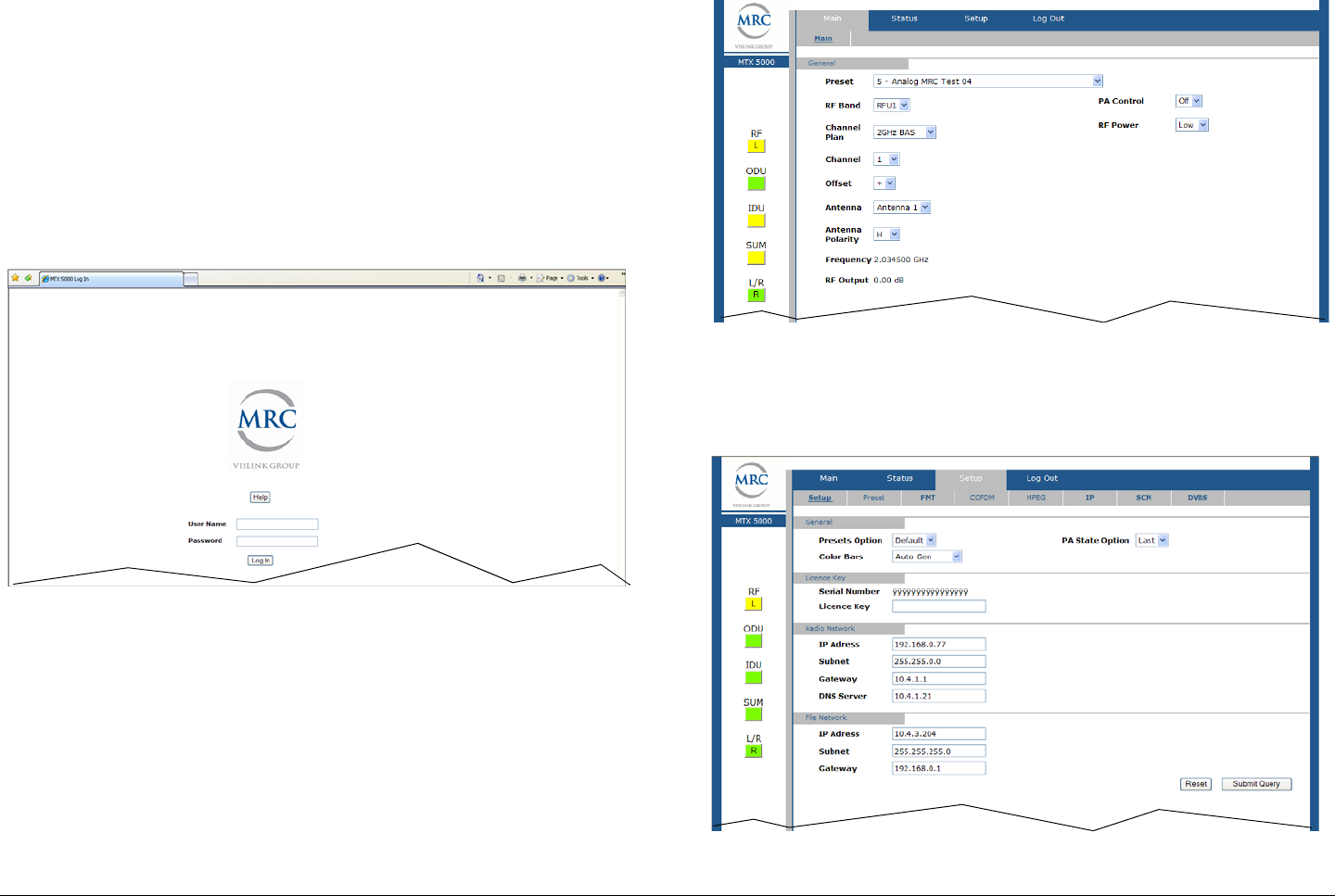
Advanced Operations 5-79MTX5000 User and Technical Manual
11. At the remote PC, open your web browser, enter the IP
address for your MTX5000 IDU, and press the
keyboard Enter key. The IP address should be
entered as follows:
http://XXX.XXX.X.XX/nfs/main/html
12. After a short delay, observe the remote log in screen is
displayed. See Figure 5-186.
Figure 5-186: Remote Log In Screen - Typical
13. Enter your administrator user name in the User Name
text box, enter your administrator password in the
Password text box, select the Log In option button,
and observe the MTX50000 Main Page is displayed.
See Figure 5-187.
Figure 5-187: MTX5000 Main Page - Typical
14. Select the Setup tab and observe the Setup page is
displayed by default. See Figure 5-188.
Figure 5-188: Setup Tab - Typical

Advanced Operations 5-80MTX5000 User and Technical Manual
Note In the following step, if a factory default digital
COFDM Preset is to be used to prepare a new
Preset configuration, select the Default option.
If a custom user digital COFDM Preset is to be
updated or is to be used to prepare a new Preset,
select the User option.
15. Use the Presets Option pull-down menu and select
Default or User, as required.
16. Use the Color Bars pull-down menu and select Off,
On, Auto Gen, or Auto Standby, as required.
17. Use the PA State Option pull-down menu to select
Off or Last, as required, and select the Submit option
button.
18. Select the Main tab and observe the Main page is
displayed.
19. Use the Preset pull-down menu to select the default or
user custom digital COFDM Preset required.
20. Select the Setup tab and observe the Setup page is
displayed.
21. Select the COFDM tab and observe the COFDM page
is displayed.
22. Use the Constellation pull-down menu to select
QPSK, 16-QAM, or 64-QAM, as required.
23. Use the FEC pull-down menu to select 1/2, 2/3, 3/4,
5/6, or 7/8, as required.
24. Use the Guard Interval pull-down menu to select
1/32, 1/16, 1/8, or 1/4, as required.
25. Use the RF B/W pull-down menu to select 6 MHz, 7
MHz, 8 MHz, 10 MHz, or 20 MHz, as required.
26. Select the Submit option button.
27. Select the MPEG tab and observe the MPEG page is
displayed.
28. Use the General - Spectrum Invert pull-down menu
to select Normal or Inverted, as required.
29. Use the Video In - Input pull-down menu to select the
input required.
30. Use the Video Input - Noise Reduction pull-down
menu to select On or Off, as required.
31. Use the Video Input - SDI Autoline pull-down menu
to select On or Off, as required.
32. Use the Video Input - HD Test Pattern pull-down
menu to select On or Off, as required.
33. Use the Audio 1 - Mode pull-down menu to select
Dual Mono or Stereo, as required.
34. Use the Audio 1 - Input pull-down menu to select
Test Tone, Analog, SDI Emb, AES-EBU or Channel
Ident, as required.
35. Use the Audio 1 - Standard pull-down menu to select
Off, MPEG Layer II, Linear PCM, or MPEG Layer I,
as required.
36. Use the Audio 1 - Bit Rate pull-down menu to select
the bit rate required.
37. Use the Audio 2 - Mode pull-down menu to select
Dual Mono or Stereo, as required.
38. Use the Audio 2 - Input pull-down menu to select
Test Tone, Analog, SDI Emb, AES-EBU or Channel
Ident, as required.
39. Use the Audio 2 - Standard pull-down menu to select
Off, MPEG Layer II, Linear PCM, or MPEG Layer I,
as required.
40. Use the Audio 2 - Bit Rate pull-down menu to select
the bit rate required.

Advanced Operations 5-81MTX5000 User and Technical Manual
41. Use the Audio 2 - Balance pull-down menu to select
Unbalanced or Balanced, as required.
42. Use the Encoder - Mode pull-down menu to select
Standard or Low Delay, as required.
43. Use the Encoder - Bit Rate text box to enter the bit
rate required.
44. Use the Encoder - Bit Rate Auto pull-down menu to
select On or Off, as required.
45. Use the Encoder - PTS per Picture pull-down menu
to select On or Off, as required.
46. Use the Encoder - Horiz Resolution pull-down menu
to select 720, 704, 544, 480 or 352, as required.
47. Use the Encoder - Profile pull-down menu to select
MP@HL or 422P@HL, as required.
Note In the following step, if the Bit Rate Auto pull-down
menu option selected was On, the ASI Bit Rate
text box is inactive and cannot be changed. Go to
step 49.
If the Bit Rate Auto pull-down menu option
selected was Off, the ASI Bit Rate text box is
active and the bit rate can be changed.
48. Select the Encoder - ASI Bit Rate text box and enter
the bit rate required.
Note In the following step, if the Remux pull-down menu
On option is selected, the Bit Rate Auto pull-down
menu will become inactive, the ASI Bit Rate text
box becomes active, and the bit rate can be
changed.
49. Use the Encoder - Remux pull-down menu to select
On or Off, as required.
50. Select the Encoder - GOP Length text box and enter
the group of pictures length required.
51. Use the Encoder - Aspect ratio pull-down menu to
select 16:9 or 4:3, as required.
52. Use the Encoder - VBI pull-down menu to select On
or Off, as required.
53. Select the PID - Video text box and enter the program
identifier, as required.
54. Select the PID - PCR text box and enter the program
identifier, as required.
55. Select the PID - PMT text box and enter the program
identifier, as required.
56. Select the PID - Audio 2 text box and enter the
program identifier, as required.
57. Select the PID - Data text box and enter the program
identifier, as required.
58. Select the PID - Audio 1 text box and enter the
program identifier, as required.
59. Select the Encoding - Service Name text box and
enter the service name, as required.
60. Select the Encoding - Network Name text box and
enter the network name, as required.
61. Use the Encoding - Data Enable pull-down menu to
select Off, TTV Format, CJM2 Format, or Low Delay
CJM2, as required.
62. Use the Encoding - Baud Rate pull-down menu to
select 1200, 2400, 4800, 9600, 19200, or 38400, as
required.
63. Select the Submit option button.

Advanced Operations 5-82MTX5000 User and Technical Manual
64. Select the Preset tab and observe the Preset page is
displayed.
Notes In the following steps, if a factory default digital
COFDM Preset was used as a “make-from” to
prepare this custom Preset, the Preset Text text
box and the Preset Number text box must be
changed. You cannot change or overwrite any
factory default Presets!
If a custom digital COFDM Preset was used as a
“make-from” to prepare this custom Preset, a brief
description of the custom Preset should be entered
in the Preset Text text box for easy identification
purposes. The Preset number must be changed
only if you do not wish to overwrite the custom
Preset.
65. Select the Preset Text text box and enter a unique
digital COFDM Preset description.
Note If you used a factory Default Preset or a custom
User Preset as a “make-from” and you want to add
the new Preset to the list of User Presets
contained in your MTX5000 IDU, you must know
the highest user Preset number contained in your
IDU. To add the new Preset to the list of User
Presets, go to step 66.
If you used a custom User Preset as a “make-
from” and you want to use it to replace (overwrite)
an existing custom User Preset, go to step 68.
66. Select the Preset Number text box and enter any
Preset number that is higher than the current highest
Preset in your MTX5000 IDU.
67. Select the Submit option button and observe that the
Preset Number automatically displays the next higher
Preset number available in the Preset User list. Go to
step 69.
68. Select the Preset Number text box, enter the Preset
number that you wish to overwrite, and select the
Submit option button.
69. Observe the new Preset configuration has been
loaded into the MTX5000 IDU and the new Preset
name and Preset number are displayed on the Main
page.
5.5.3 Create or Update Custom Digital ASI Preset
Configuration in Remote Mode
The procedure required to create a new custom digital ASI
Preset configuration or to update an existing Preset configuration
in the Remote mode is contained in the following steps.
When preparing a new digital ASI Preset, you must first select an
existing digital ASI Preset from either the digital ASI factory
default Preset or from your own custom digital ASI Presets. The
selected Preset will be used as a “make-from” to prepare the
new digital ASI Preset configuration.
Please note that while factory default digital ASI Presets may be
used to prepare a new Preset configuration, these factory
default Presets cannot be changed or deleted. They can only
be used as “make-froms”.
When the new configuration is prepared using the factory default
Preset, it cannot be saved with the factory Preset number or

Advanced Operations 5-83MTX5000 User and Technical Manual
Preset name. A new Preset number and Preset name must be
assigned to the new Preset.
When using a custom Preset as a “make-from”, the new Preset
should be saved with a new Preset number.
If you select an existing Preset number when saving the new
Preset, the original custom Preset will be overwritten and cannot
be recovered. The only way to restore a Preset that has been
overwritten is to re-enter the custom Preset data from scratch.
If you are updating configuration settings on an existing custom
Preset, when you save the configuration settings, the Preset
number will automatically be increased to the next available
Preset number. You must enter and save the configuration
settings using the original Preset number.
Note In the following steps, the color LCD display option
buttons and pull-down menu options may be
selected using either the touch screen or the
function keys and the SEL key.
1. Verify the MTX5000 IDU is powered up. See
”Powering the MTX5000 System” on page 3-7.
2. Observe the Main screen is displayed. See Figure 5-
189.
Figure 5-189: Main Screen - Typical
3. Select the L/R option button for L (Local), as required.
4. Select the PA operation button for PA Off, as required
5. Select the Setup option button and observe the Setup
screen is displayed.
6. Select the Radio option button and observe the Radio
screen is displayed.
7. Select the Next option button and observe the Radio -
2 screen is displayed.
8. Select the Remote Ctrl Option button and observe
the Select Remote Ctrl Opt screen is displayed.
9. Select the Remote option button and observe the
Radio - 2 screen is displayed.
10. Select the Main option button, observe the Main
screen is displayed, and observe the L/R option button
indicates R (Remote).
Note In the following step, XXX.XXX.X.XX is the IP
address of your MTX5000 IDU.
Channel 1 0Offset
Antenna Ant. Pol.Antenna1 H
RFU1
No RF
RF Band
Preset A Analog
4.83 & 5.8, 3MHz Vid Dev
RF Output XX
dBm
<- Status Setup Status ->
PA Off
SUM
ODU
IDU
RF
L/R
L
L
PA
Operation
Button
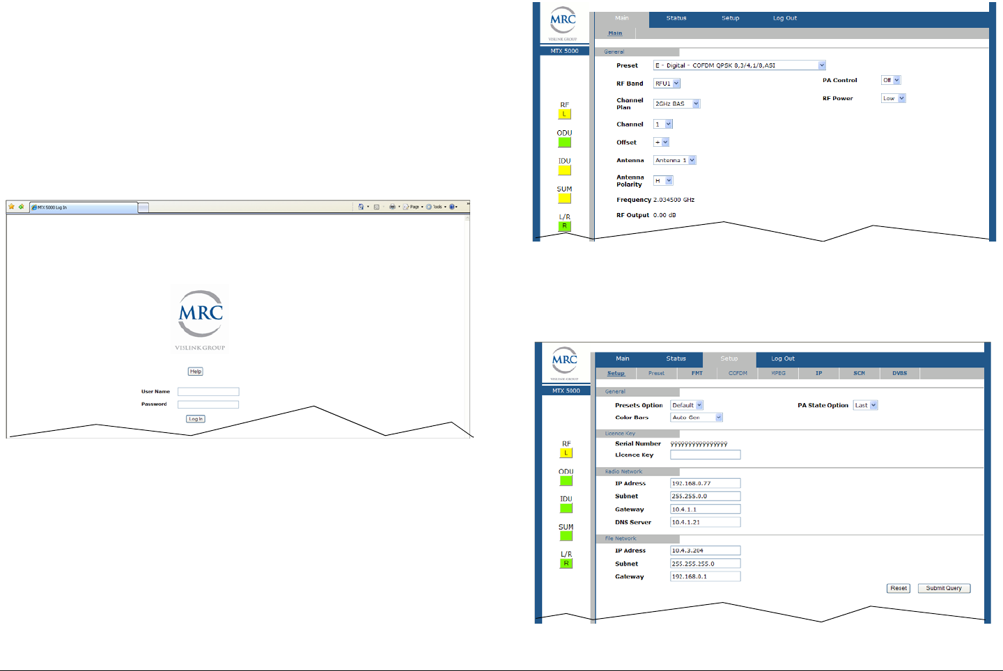
Advanced Operations 5-84MTX5000 User and Technical Manual
11. At the remote PC, open your web browser, enter the IP
address for your MTX5000 IDU, and press the
keyboard Enter key. The IP address should be
entered as follows:
http://XXX.XXX.X.XX/nfs/main/html
12. After a short delay, observe the remote log in screen is
displayed. See Figure 5-190.
Figure 5-190: Remote Log In Screen - Typical
13. Enter your administrator user name in the User Name
text box, enter your administrator password in the
Password text box, select the Log In option button,
and observe the MTX50000 Main Page is displayed.
See Figure 5-191.
Figure 5-191: MTX5000 Main Page - Typical
14. Select the Setup tab and observe the Setup page is
displayed by default. See Figure 5-192.
Figure 5-192: Setup Tab - Typical

Advanced Operations 5-85MTX5000 User and Technical Manual
Note In the following step, if a factory default digital ASI
Preset is to be used to prepare a new Preset
configuration, select the Default option.
If a custom digital ASI Preset is to be updated or is
to be used to prepare a new Preset, select the
User option.
15. Use the Presets Option pull-down menu and select
Default or User, as required.
16. Use the Color Bars pull-down menu and select Off,
On, Auto Gen, or Auto Standby, as required.
17. Use the PA State Option pull-down menu to select
Off or Last, as required, and select the Submit option
button.
18. Select the Main tab and observe the Main page is
displayed.
19. Use the Preset pull-down menu to select the default or
user custom digital ASI Preset required.
20. Select the Setup tab and observe the Setup page is
displayed.
21. Select the COFDM tab and observe the COFDM page
is displayed.
22. Use the Constellation pull-down menu to select
QPSK, 16-QAM, or 64-QAM, as required.
23. Use the FEC pull-down menu to select 1/2, 2/3, 3/4,
5/6, or 7/8, as required.
24. Use the Guard Interval pull-down menu to select
1/32, 1/16, 1/8, or 1/4, as required.
25. Use the RF B/W pull-down menu to select 6 MHz, 7
MHz, 8 MHz, 10 MHz, or 20 MHz, as required.
26. Select the Submit option button.
27. Select the Preset tab and observe the Preset page is
displayed.
Notes In the following steps, if a factory default digital ASI
Preset was used as a “make-from” to prepare this
custom Preset, the Preset Text text box and the
Preset Number text box must be changed. You
cannot change or overwrite any factory default
Presets!
If a custom digital ASI Preset was used as a
“make-from” to prepare this custom Preset, a brief
description of the custom Preset should be entered
in the Preset Text text box for easy identification
purposes. The Preset number must be changed
only if you do not wish to overwrite the custom
Preset.
28. Select the Preset Text text box and enter a unique
digital ASI Preset description.
Note If you used a factory Default Preset or a custom
User Preset as a “make-from” and you want to add
the new Preset to the list of User Presets
contained in your MTX5000 IDU, you must know
the highest user Preset number contained in your
IDU. To add the new Preset to the list of User
Presets, go to step 29.
If you used a custom User Preset as a “make-
from” and you want to use it to replace (overwrite)
an existing custom User Preset, go to step 31.

Advanced Operations 5-86MTX5000 User and Technical Manual
29. Select the Preset Number text box and enter any
Preset number that is higher than the current highest
Preset in your MTX5000 IDU.
30. Select the Submit option button and observe that the
Preset Number automatically displays the next higher
Preset number available in the Preset User list. Go to
step 32.
31. Select the Preset Number text box, enter the Preset
number that you wish to overwrite, and select the
Submit option button.
32. Observe the new Preset configuration has been
loaded into the MTX5000 IDU and the new Preset
name and Preset number are displayed on the Main
page.
5.5.4 Create or Update Custom Digital LMS-T
Preset Configuration in Remote Mode
The procedure required to create a new custom digital LMS-T
Preset configuration or to update an existing Preset configuration
in the Remote mode is contained in the following steps.
When preparing a new digital LMS-T Preset, you must first select
an existing digital LMS-T Preset from either one of the digital
LMS-T factory default Presets or from your own custom digital
LMS-T Presets. The selected Preset will be used as a “make-
from” to prepare the new digital LMS-T Preset configuration.
Please note that while factory default digital LMS-T Presets may
be used to prepare a new Preset configuration, these factory
default Presets cannot be changed or deleted. They can only
be used as “make-froms”.
When the new configuration is prepared using the factory default
Preset, it cannot be saved with the factory Preset number or
Preset name. A new Preset number and Preset name must be
assigned to the new Preset.
When using a custom Preset as a “make-from”, the new Preset
should be saved with a new Preset number.
If you select an existing Preset number when saving the new
Preset, the original custom Preset will be overwritten and cannot
be recovered. The only way to restore a Preset that has been
overwritten is to re-enter the custom Preset data from scratch.
If you are updating configuration settings on an existing custom
Preset, when you save the configuration settings, the Preset
number will automatically be increased to the next available
Preset number. You must enter and save the configuration
settings using the original Preset number.
Note In the following steps, the color LCD display option
buttons and pull-down menu options may be
selected using either the touch screen or the
function keys and the SEL key.
1. Verify the MTX5000 IDU is powered up. See
”Powering the MTX5000 System” on page 3-7.
2. Observe the Main screen is displayed. See Figure 5-
193 on page 5-87.
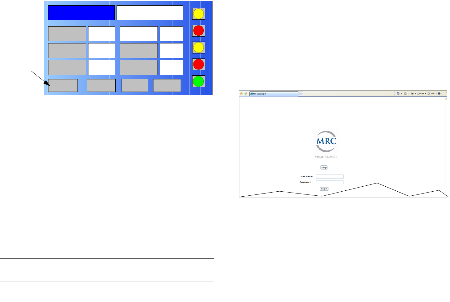
Advanced Operations 5-87MTX5000 User and Technical Manual
Figure 5-193: Main Screen - Typical
3. Select the L/R option button for L (Local), as required.
4. Select the PA operation button for PA Off, as required
5. Select the Setup option button and observe the Setup
screen is displayed.
6. Select the Radio option button and observe the Radio
screen is displayed.
7. Select the Next option button and observe the Radio -
2 screen is displayed.
8. Select the Remote Ctrl Option button and observe
the Select Remote Ctrl Opt screen is displayed.
9. Select the Remote option button and observe the
Radio - 2 screen is displayed.
10. Select the Main option button, observe the Main
screen is displayed, and observe the L/R option button
indicates R (Remote).
Note In the following step, XXX.XXX.X.XX is the IP
address of your MTX5000 IDU.
Channel 1 0Offset
Antenna Ant. Pol.Antenna1 H
RFU1
No RF
RF Band
Preset A Analog
4.83 & 5.8, 3MHz Vid Dev
RF Output XX
dBm
<- Status Setup Status ->
PA Off
SUM
ODU
IDU
RF
L/R
L
L
PA
Operation
Button
11. At the remote PC, open your web browser, enter the IP
address for your MTX5000 IDU, and press the
keyboard Enter key. The IP address should be
entered as follows:
http://XXX.XXX.X.XX/nfs/main/html
12. After a short delay, observe the remote log in screen is
displayed. See Figure 5-194.
Figure 5-194: Remote Log In Screen - Typical
13. Enter your administrator user name in the User Name
text box, enter your administrator password in the
Password text box, select the Log In option button,
and observe the MTX50000 Main Page is displayed.
See Figure 5-195 on page 5-88.
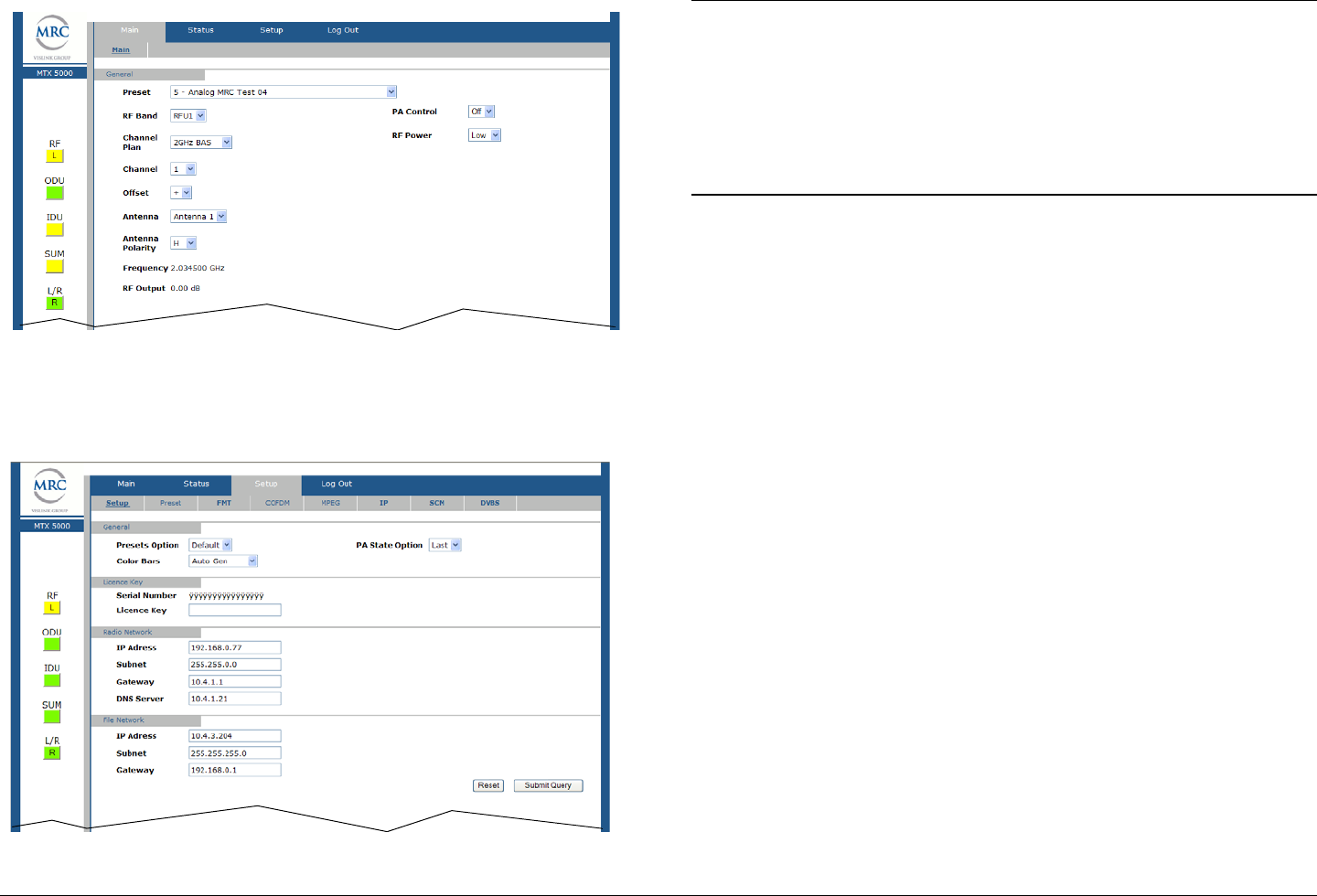
Advanced Operations 5-88MTX5000 User and Technical Manual
Figure 5-195: MTX5000 Main Page - Typical
14. Select the Setup tab and observe the Setup page is
displayed by default. See Figure 5-196.
Figure 5-196: Setup Tab - Typical
Note In the following step, if a factory default digital
LMS-T Preset is to be used to prepare a new
Preset configuration, select the Default option.
If a custom digital LMS-T Preset is to be updated or
is to be used to prepare a new Preset, select the
User option.
15. Use the Presets Option pull-down menu and select
Default or User, as required.
16. Use the Color Bars pull-down menu and select Off,
On, Auto Gen, or Auto Standby, as required.
17. Use the PA State Option pull-down menu to select
Off or Last, as required, and select the Submit option
button.
18. Select the Main tab and observe the Main page is
displayed.
19. Use the Preset pull-down menu to select the default or
user custom digital LMS-T Preset required.
20. Select the Setup tab and observe the Setup page is
displayed.
21. Select the COFDM tab and observe the COFDM page
is displayed.
22. Use the Constellation pull-down menu to select
QPSK, 16-QAM, or 64-QAM, as required.
23. Use the FEC pull-down menu to select 1/2, 2/3, 3/4,
5/6, or 7/8, as required.
24. Use the Guard Interval pull-down menu to select
1/32, 1/16, 1/8, or 1/4, as required.
25. Use the RF B/W pull-down menu to select 6 MHz, 7
MHz, 8 MHz, 10 MHz, or 20 MHz, as required.

Advanced Operations 5-89MTX5000 User and Technical Manual
26. Select the Submit option button.
27. Select the MPEG tab and observe the MPEG page is
displayed.
28. Use the General - Spectrum Invert pull-down menu
to select Normal or Inverted, as required.
29. Use the Video In - Input pull-down menu to select the
input required.
30. Use the Video Input - Noise Reduction pull-down
menu to select On or Off, as required.
31. Use the Video Input - SDI Autoline pull-down menu
to select On or Off, as required.
32. Use the Video Input - HD Test Pattern pull-down
menu to select On or Off, as required.
33. Use the Audio 1 - Mode pull-down menu to select
Dual Mono or Stereo, as required.
34. Use the Audio 1 - Input pull-down menu to select
Test Tone, Analog, SDI Emb, AES-EBU or Channel
Ident, as required.
35. Use the Audio 1 - Standard pull-down menu to select
Off, MPEG Layer II, Linear PCM, or MPEG Layer I,
as required.
36. Use the Audio 1 - Bit Rate pull-down menu to select
the bit rate required.
37. Use the Audio 2 - Mode pull-down menu to select
Dual Mono or Stereo, as required.
38. Use the Audio 2 - Input pull-down menu to select
Test Tone, Analog, SDI Emb, AES-EBU or Channel
Ident, as required.
39. Use the Audio 2 - Standard pull-down menu to select
Off, MPEG Layer II, Linear PCM, or MPEG Layer I,
as required.
40. Use the Audio 2 - Bit Rate pull-down menu to select
the bit rate required.
41. Use the Audio 2 - Balance pull-down menu to select
Unbalanced or Balanced, as required.
42. Use the Encoder - Mode pull-down menu to select
Standard or Low Delay, as required.
43. Use the Encoder - Bit Rate text box to enter the bit
rate required.
44. Use the Encoder - Bit Rate Auto pull-down menu to
select On or Off, as required.
45. Use the Encoder - PTS per Picture pull-down menu
to select On or Off, as required.
46. Use the Encoder - Horiz Resolution pull-down menu
to select 720, 704, 544, 480 or 352, as required.
47. Use the Encoder - Profile pull-down menu to select
MP@HL or 422P@HL, as required.
Note In the following step, if the Bit Rate Auto pull-down
menu option selected was On, the ASI Bit Rate
text box is inactive and cannot be changed. Go to
step 49.
If the Bit Rate Auto pull-down menu option
selected was Off, the ASI Bit Rate text box is
active and the bit rate can be changed.
48. Select the Encoder - ASI Bit Rate text box and enter
the bit rate required.

Advanced Operations 5-90MTX5000 User and Technical Manual
Note In the following step, if the Remux pull-down menu
On option is selected, the Bit Rate Auto pull-down
menu will become inactive, the ASI Bit Rate text
box becomes active, and the bit rate can be
changed.
49. Use the Encoder - Remux pull-down menu to select
On or Off, as required.
50. Select the Encoder - GOP Length text box and enter
the group of pictures length required.
51. Use the Encoder - Aspect ratio pull-down menu to
select 16:9 or 4:3, as required.
52. Use the Encoder - VBI pull-down menu to select On
or Off, as required.
53. Select the PID - Video text box and enter the program
identifier, as required.
54. Select the PID - PCR text box and enter the program
identifier, as required.
55. Select the PID - PMT text box and enter the program
identifier, as required.
56. Select the PID - Audio 2 text box and enter the
program identifier, as required.
57. Select the PID - Data text box and enter the program
identifier, as required.
58. Select the PID - Audio 1 text box and enter the
program identifier, as required.
59. Select the Encoding - Service Name text box and
enter the service name, as required.
60. Select the Encoding - Network Name text box and
enter the network name, as required.
61. Use the Encoding - Data Enable pull-down menu to
select Off, TTV Format, CJM2 Format, or Low Delay
CJM2, as required.
62. Use the Encoding - Baud Rate pull-down menu to
select 1200, 2400, 4800, 9600, 19200, or 38400, as
required.
63. Select the Submit option button.
64. Select the Preset tab and observe the Preset page is
displayed.
Notes In the following steps, if a factory default digital
LMS-T Preset was used as a “make-from” to
prepare this custom Preset, the Preset Text text
box and the Preset Number text box must be
changed. You cannot change or overwrite any
factory default Presets!
If a custom digital LMS-T Preset was used as a
“make-from” to prepare this custom Preset, a brief
description of the custom Preset should be entered
in the Preset Text text box for easy identification
purposes. The Preset number must be changed
only if you do not wish to overwrite the custom
Preset.
65. Select the Preset Text text box and enter a unique
digital LMS-T Preset description.

Advanced Operations 5-91MTX5000 User and Technical Manual
Note If you used a factory Default Preset or a custom
User Preset as a “make-from” and you want to add
the new Preset to the list of User Presets
contained in your MTX5000 IDU, you must know
the highest user Preset number contained in your
IDU. To add the new Preset to the list of User
Presets, go to step 66.
If you used a custom User Preset as a “make-
from” and you want to use it to replace (overwrite)
an existing custom User Preset, go to step 68.
66. Select the Preset Number text box and enter any
Preset number that is higher than the current highest
Preset in your MTX5000 IDU.
67. Select the Submit option button and observe that the
Preset Number automatically displays the next higher
Preset number available in the Preset User list. Go to
step 69.
68. Select the Preset Number text box, enter the Preset
number that you wish to overwrite, and select the
Submit option button.
69. Observe the new Preset configuration has been
loaded into the MTX5000 IDU and the new Preset
name and Preset number are displayed on the Main
page.
5.5.5 Create or Update Custom Digital DVB-S
Preset Configuration in Remote Mode
The procedure required to create a new custom digital DVB-S
Preset configuration or to update an existing Preset configuration
in the Remote mode is contained in the following steps.
When preparing a new digital DVB-S Preset, you must first
select an existing digital DVB-S Preset from either the digital
DVB-S factory default Preset or from your own custom digital
DVB-S Presets. The selected Preset will be used as a “make-
from” to prepare the new digital DVB-S Preset configuration.
Please note that while factory default digital DVB-S Presets may
be used to prepare a new Preset configuration, these factory
default Presets cannot be changed or deleted. They can only
be used as “make-froms”.
When the new configuration is prepared using the factory default
Preset, it cannot be saved with the factory Preset number or
Preset name. A new Preset number and Preset name must be
assigned to the new Preset.
When using a custom Preset as a “make-from”, the new Preset
should be saved with a new Preset number.
If you select an existing Preset number when saving the new
Preset, the original custom Preset will be overwritten and cannot
be recovered. The only way to restore a Preset that has been
overwritten is to re-enter the custom Preset data from scratch.
If you are updating configuration settings on an existing custom
Preset, when you save the configuration settings, the Preset
number will automatically be increased to the next available
Preset number. You must enter and save the configuration
settings using the original Preset number.
Note In the following steps, the color LCD display option
buttons and pull-down menu options may be
selected using either the touch screen or the
function keys and the SEL key.
1. Verify the MTX5000 IDU is powered up. See
”Powering the MTX5000 System” on page 3-7.
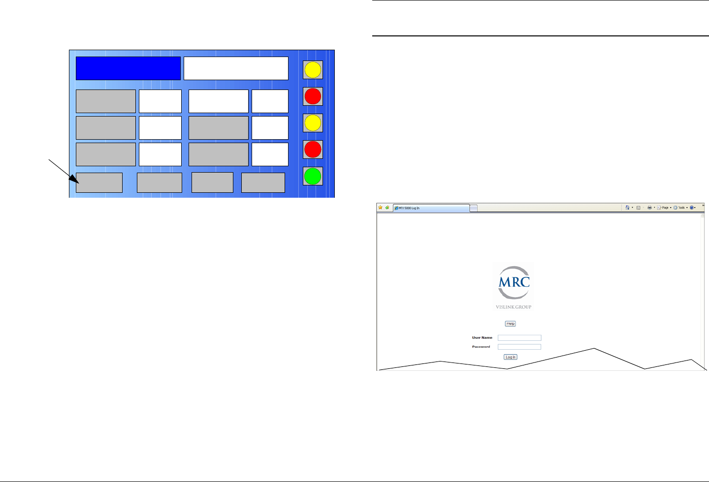
Advanced Operations 5-92MTX5000 User and Technical Manual
2. Observe the Main screen is displayed. See Figure 5-
197.
Figure 5-197: Main Screen - Typical
3. Select the L/R option button for L (Local), as required.
4. Select the PA operation button for PA Off, as required
5. Select the Setup option button and observe the Setup
screen is displayed.
6. Select the Radio option button and observe the Radio
screen is displayed.
7. Select the Next option button and observe the Radio -
2 screen is displayed.
8. Select the Remote Ctrl Option button and observe
the Select Remote Ctrl Opt screen is displayed.
9. Select the Remote option button and observe the
Radio - 2 screen is displayed.
10. Select the Main option button, observe the Main
screen is displayed, and observe the L/R option button
indicates R (Remote).
Channel 1 0Offset
Antenna Ant. Pol.Antenna1 H
RFU1
No RF
RF Band
Preset A Analog
4.83 & 5.8, 3MHz Vid Dev
RF Output XX
dBm
<- Status Setup Status ->
PA Off
SUM
ODU
IDU
RF
L/R
L
L
PA
Operation
Button
Note In the following step, XXX.XXX.X.XX is the IP
address of your MTX5000 IDU.
11. At the remote PC, open your web browser, enter the IP
address for your MTX5000 IDU, and press the
keyboard Enter key. The IP address should be
entered as follows:
http://XXX.XXX.X.XX/nfs/main/html
12. After a short delay, observe the remote log in screen is
displayed. See Figure 5-198.
Figure 5-198: Remote Log In Screen - Typical
13. Enter your administrator user name in the User Name
text box, enter your administrator password in the
Password text box, select the Log In option button,
and observe the MTX50000 Main Page is displayed.
See Figure 5-199 on page 5-93.
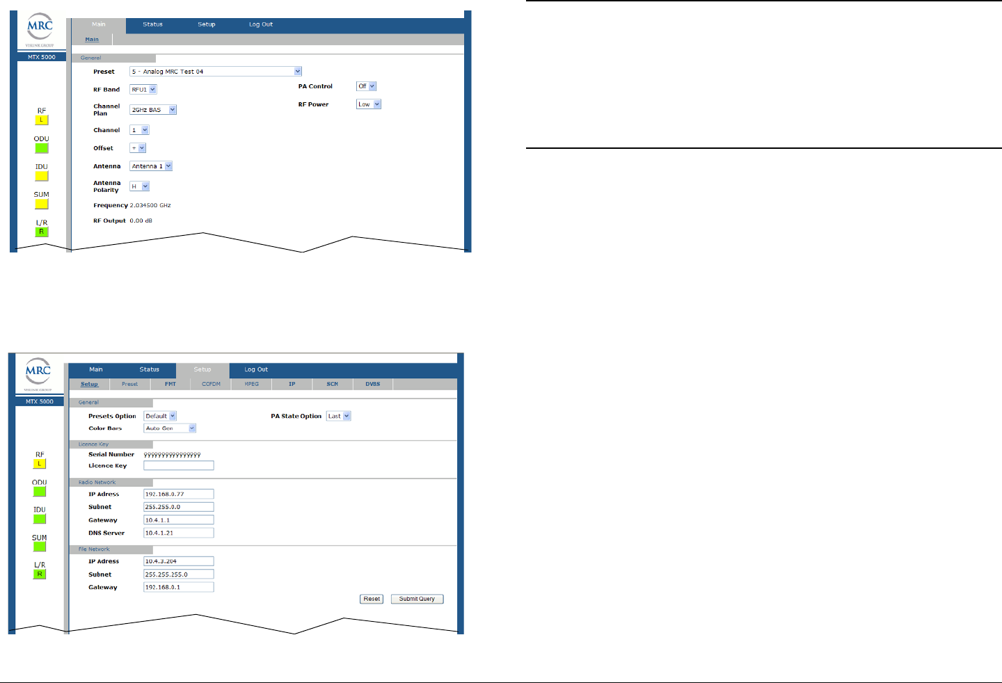
Advanced Operations 5-93MTX5000 User and Technical Manual
Figure 5-199: MTX5000 Main Page - Typical
14. Select the Setup tab and observe the Setup page is
displayed by default. See Figure 5-200.
Figure 5-200: Setup Tab - Typical
Note In the following step, if a factory default digital
DVB-S Preset is to be used to prepare a new
Preset configuration, select the Default option.
If a custom digital DVB-S Preset is to be updated
or is to be used to prepare a new Preset, select the
User option.
15. Use the Presets Option pull-down menu and select
Default or User, as required.
16. Use the Color Bars pull-down menu and select Off,
On, Auto Gen, or Auto Standby, as required.
17. Use the PA State Option pull-down menu to select
Off or Last, as required, and select the Submit option
button.
18. Select the Main tab and observe the Main page is
displayed.
19. Use the Preset pull-down menu to select the default or
user custom digital DVB-S Preset required.
20. Select the Setup tab and observe the Setup page is
displayed.
21. Select the COFDM tab and observe the COFDM page
is displayed.
22. Use the Constellation pull-down menu to select
QPSK, 16-QAM, or 64-QAM, as required.
23. Use the FEC pull-down menu to select 1/2, 2/3, 3/4,
5/6, or 7/8, as required.
24. Use the Guard Interval pull-down menu to select
1/32, 1/16, 1/8, or 1/4, as required.
25. Use the RF B/W pull-down menu to select 6 MHz, 7
MHz, 8 MHz, 10 MHz, or 20 MHz, as required.
26. Select the Submit option button.

Advanced Operations 5-94MTX5000 User and Technical Manual
27. Select the MPEG tab and observe the MPEG page is
displayed.
28. Use the General - Spectrum Invert pull-down menu
to select Normal or Inverted, as required.
29. Use the Video In - Input pull-down menu to select the
input required.
30. Use the Video Input - Noise Reduction pull-down
menu to select On or Off, as required.
31. Use the Video Input - SDI Autoline pull-down menu
to select On or Off, as required.
32. Use the Video Input - HD Test Pattern pull-down
menu to select On or Off, as required.
33. Use the Audio 1 - Mode pull-down menu to select
Dual Mono or Stereo, as required.
34. Use the Audio 1 - Input pull-down menu to select
Test Tone, Analog, SDI Emb, AES-EBU or Channel
Ident, as required.
35. Use the Audio 1 - Standard pull-down menu to select
Off, MPEG Layer II, Linear PCM, or MPEG Layer I,
as required.
36. Use the Audio 1 - Bit Rate pull-down menu to select
the bit rate required.
37. Use the Audio 2 - Mode pull-down menu to select
Dual Mono or Stereo, as required.
38. Use the Audio 2 - Input pull-down menu to select
Test Tone, Analog, SDI Emb, AES-EBU or Channel
Ident, as required.
39. Use the Audio 2 - Standard pull-down menu to select
Off, MPEG Layer II, Linear PCM, or MPEG Layer I,
as required.
40. Use the Audio 2 - Bit Rate pull-down menu to select
the bit rate required.
41. Use the Audio 2 - Balance pull-down menu to select
Unbalanced or Balanced, as required.
42. Use the Encoder - Mode pull-down menu to select
Standard or Low Delay, as required.
43. Use the Encoder - Bit Rate text box to enter the bit
rate required.
44. Use the Encoder - Bit Rate Auto pull-down menu to
select On or Off, as required.
45. Use the Encoder - PTS per Picture pull-down menu
to select On or Off, as required.
46. Use the Encoder - Horiz Resolution pull-down menu
to select 720, 704, 544, 480 or 352, as required.
47. Use the Encoder - Profile pull-down menu to select
MP@HL or 422P@HL, as required.
Note In the following step, if the Bit Rate Auto pull-down
menu option selected was On, the ASI Bit Rate
text box is inactive and cannot be changed. Go to
step 49.
If the Bit Rate Auto pull-down menu option
selected was Off, the ASI Bit Rate text box is
active and the bit rate can be changed.
48. Select the Encoder - ASI Bit Rate text box and enter
the bit rate required.
Note In the following step, if the Remux pull-down menu
On option is selected, the Bit Rate Auto pull-down
menu will become inactive, the ASI Bit Rate text
box becomes active, and the bit rate can be
changed.

Advanced Operations 5-95MTX5000 User and Technical Manual
49. Use the Encoder - Remux pull-down menu to select
On or Off, as required.
50. Select the Encoder - GOP Length text box and enter
the group of pictures length required.
51. Use the Encoder - Aspect ratio pull-down menu to
select 16:9 or 4:3, as required.
52. Use the Encoder - VBI pull-down menu to select On
or Off, as required.
53. Select the PID - Video text box and enter the program
identifier, as required.
54. Select the PID - PCR text box and enter the program
identifier, as required.
55. Select the PID - PMT text box and enter the program
identifier, as required.
56. Select the PID - Audio 2 text box and enter the
program identifier, as required.
57. Select the PID - Data text box and enter the program
identifier, as required.
58. Select the PID - Audio 1 text box and enter the
program identifier, as required.
59. Select the Encoding - Service Name text box and
enter the service name, as required.
60. Select the Encoding - Network Name text box and
enter the network name, as required.
61. Use the Encoding - Data Enable pull-down menu to
select Off, TTV Format, CJM2 Format, or Low Delay
CJM2, as required.
62. Use the Encoding - Baud Rate pull-down menu to
select 1200, 2400, 4800, 9600, 19200, or 38400, as
required.
63. Select the Submit option button.
64. Select the DVB-S tab and observe the DVB-S page is
displayed.
65. Use the Roll Off pull-down menu to select 20%, 25%,
or 35%, as required.
66. Select the Symbol Rate text box and enter the symbol
rate required.
67. Select the Preset tab and observe the Preset page is
displayed.
Notes In the following steps, if a factory default digital
DVB-S Preset was used as a “make-from” to
prepare this custom Preset, the Preset Text text
box and the Preset Number text box must be
changed. You cannot change or overwrite any
factory default Presets!
If a custom digital DVB-S Preset was used as a
“make-from” to prepare this custom Preset, a brief
description of the custom Preset should be entered
in the Preset Text text box for easy identification
purposes. The Preset number must be changed
only if you do not wish to overwrite the custom
Preset.
68. Select the Preset Text text box and enter a unique
digital DVB-S Preset description.

Advanced Operations 5-96MTX5000 User and Technical Manual
Note If you used a factory Default Preset or a custom
User Preset as a “make-from” and you want to add
the new Preset to the list of User Presets
contained in your MTX5000 IDU, you must know
the highest user Preset number contained in your
IDU. To add the new Preset to the list of User
Presets, go to step 69.
If you used a custom User Preset as a “make-
from” and you want to use it to replace (overwrite)
an existing custom User Preset, go to step 71.
69. Select the Preset Number text box and enter any
Preset number that is higher than the current highest
Preset in your MTX5000 IDU.
70. Select the Submit option button and observe that the
Preset Number automatically displays the next higher
Preset number available in the Preset User list. Go to
step 72.
71. Select the Preset Number text box, enter the Preset
number that you wish to overwrite, and select the
Submit option button.
72. Observe the new Preset configuration has been
loaded into the MTX5000 IDU and the new Preset
name and Preset number are displayed on the Main
page.
5.5.6 Create or Update Custom Digital IP Preset
Configuration in Remote Mode
The procedure required to create a new custom digital IP Preset
configuration or to update an existing Preset configuration in the
Remote mode is contained in the following steps.
When preparing a new digital IP Preset, you must first select an
existing digital IP Preset from either the digital IP factory default
Preset or from your own custom digital IP Presets. The selected
Preset will be used as a “make-from” to prepare the new digital
IP Preset configuration.
Please note that while factory default digital IP Presets may be
used to prepare a new Preset configuration, these factory
default Presets cannot be changed or deleted. They can only
be used as “make-froms”.
When the new configuration is prepared using the factory default
Preset, it cannot be saved with the factory Preset number or
Preset name. A new Preset number and Preset name must be
assigned to the new Preset.
When using a custom Preset as a “make-from”, the new Preset
should be saved with a new Preset number.
If you select an existing Preset number when saving the new
Preset, the original custom Preset will be overwritten and cannot
be recovered. The only way to restore a Preset that has been
overwritten is to re-enter the custom Preset data from scratch.
If you are updating configuration settings on an existing custom
Preset, when you save the configuration settings, the Preset
number will automatically be increased to the next available
Preset number. You must enter and save the configuration
settings using the original Preset number.
Note In the following steps, the color LCD display option
buttons and pull-down menu options may be
selected using either the touch screen or the
function keys and the SEL key.
1. Verify the MTX5000 IDU is powered up. See
”Powering the MTX5000 System” on page 3-7.

Advanced Operations 5-97MTX5000 User and Technical Manual
2. Observe the Main screen is displayed. See Figure 5-
201.
Figure 5-201: Main Screen - Typical
3. Select the L/R option button for L (Local), as required.
4. Select the PA operation button for PA Off, as required
5. Select the Setup option button and observe the Setup
screen is displayed.
6. Select the Radio option button and observe the Radio
screen is displayed.
7. Select the Next option button and observe the Radio -
2 screen is displayed.
8. Select the Remote Ctrl Option button and observe
the Select Remote Ctrl Opt screen is displayed.
9. Select the Remote option button and observe the
Radio - 2 screen is displayed.
10. Select the Main option button, observe the Main
screen is displayed, and observe the L/R option button
indicates R (Remote).
Channel 1 0Offset
Antenna Ant. Pol.Antenna1 H
RFU1
No RF
RF Band
Preset A Analog
4.83 & 5.8, 3MHz Vid Dev
RF Output XX
dBm
<- Status Setup Status ->
PA Off
SUM
ODU
IDU
RF
L/R
L
L
PA
Operation
Button
Note In the following step, XXX.XXX.X.XX is the IP
address of your MTX5000 IDU.
11. At the remote PC, open your web browser, enter the IP
address for your MTX5000 IDU, and press the
keyboard Enter key. The IP address should be
entered as follows:
http://XXX.XXX.X.XX/nfs/main/html
12. After a short delay, observe the remote log in screen is
displayed. See Figure 5-202.
Figure 5-202: Remote Log In Screen - Typical
13. Enter your administrator user name in the User Name
text box, enter your administrator password in the
Password text box, select the Log In option button,
and observe the MTX50000 Main Page is displayed.
See Figure 5-203 on page 5-98.

Advanced Operations 5-98MTX5000 User and Technical Manual
Figure 5-203: MTX5000 Main Page - Typical
14. Select the Setup tab and observe the Setup page is
displayed by default. See Figure 5-204.
Figure 5-204: Setup Tab - Typical
Note In the following step, if a factory default digital IP
Preset is to be used to prepare a new Preset
configuration, select the Default option.
If a custom digital IP Preset is to be updated or is to
be used to prepare a new Preset, select the User
option.
15. Use the Presets Option pull-down menu and select
Default or User, as required.
16. Use the Color Bars pull-down menu and select Off,
On, Auto Gen, or Auto Standby, as required.
17. Use the PA State Option pull-down menu to select
Off or Last, as required, and select the Submit option
button.
18. Select the Main tab and observe the Main page is
displayed.
19. Use the Preset pull-down menu to select the default or
user custom digital IP Preset required.
20. Select the Setup tab and observe the Setup page is
displayed.
21. Select the COFDM tab and observe the COFDM page
is displayed.
22. Use the Constellation pull-down menu to select
QPSK, 16-QAM, or 64-QAM, as required.
23. Use the FEC pull-down menu to select 1/2, 2/3, 3/4,
5/6, or 7/8, as required.
24. Use the Guard Interval pull-down menu to select
1/32, 1/16, 1/8, or 1/4, as required.
25. Use the RF B/W pull-down menu to select 6 MHz, 7
MHz, 8 MHz, 10 MHz, or 20 MHz, as required.

Advanced Operations 5-99MTX5000 User and Technical Manual
26. Select the Submit option button.
27. Select the MPEG tab and observe the MPEG page is
displayed.
28. Use the General - Spectrum Invert pull-down menu
to select Normal or Inverted, as required.
29. Use the Video In - Input pull-down menu to select the
input required.
30. Use the Video Input - Noise Reduction pull-down
menu to select On or Off, as required.
31. Use the Video Input - SDI Autoline pull-down menu
to select On or Off, as required.
32. Use the Video Input - HD Test Pattern pull-down
menu to select On or Off, as required.
33. Use the Audio 1 - Mode pull-down menu to select
Dual Mono or Stereo, as required.
34. Use the Audio 1 - Input pull-down menu to select
Test Tone, Analog, SDI Emb, AES-EBU or Channel
Ident, as required.
35. Use the Audio 1 - Standard pull-down menu to select
Off, MPEG Layer II, Linear PCM, or MPEG Layer I,
as required.
36. Use the Audio 1 - Bit Rate pull-down menu to select
the bit rate required.
37. Use the Audio 2 - Mode pull-down menu to select
Dual Mono or Stereo, as required.
38. Use the Audio 2 - Input pull-down menu to select
Test Tone, Analog, SDI Emb, AES-EBU or Channel
Ident, as required.
39. Use the Audio 2 - Standard pull-down menu to select
Off, MPEG Layer II, Linear PCM, or MPEG Layer I,
as required.
40. Use the Audio 2 - Bit Rate pull-down menu to select
the bit rate required.
41. Use the Audio 2 - Balance pull-down menu to select
Unbalanced or Balanced, as required.
42. Use the Encoder - Mode pull-down menu to select
Standard or Low Delay, as required.
43. Use the Encoder - Bit Rate text box to enter the bit
rate required.
44. Use the Encoder - Bit Rate Auto pull-down menu to
select On or Off, as required.
45. Use the Encoder - PTS per Picture pull-down menu
to select On or Off, as required.
46. Use the Encoder - Horiz Resolution pull-down menu
to select 720, 704, 544, 480 or 352, as required.
47. Use the Encoder - Profile pull-down menu to select
MP@HL or 422P@HL, as required.
Note In the following step, if the Bit Rate Auto pull-down
menu option selected was On, the ASI Bit Rate
text box is inactive and cannot be changed. Go to
step 49.
If the Bit Rate Auto pull-down menu option
selected was Off, the ASI Bit Rate text box is
active and the bit rate can be changed.
48. Select the Encoder - ASI Bit Rate text box and enter
the bit rate required.

Advanced Operations 5-100MTX5000 User and Technical Manual
Note In the following step, if the Remux pull-down menu
On option is selected, the Bit Rate Auto pull-down
menu will become inactive, the ASI Bit Rate text
box becomes active, and the bit rate can be
changed.
49. Use the Encoder - Remux pull-down menu to select
On or Off, as required.
50. Select the Encoder - GOP Length text box and enter
the group of pictures length required.
51. Use the Encoder - Aspect ratio pull-down menu to
select 16:9 or 4:3, as required.
52. Use the Encoder - VBI pull-down menu to select On
or Off, as required.
53. Select the PID - Video text box and enter the program
identifier, as required.
54. Select the PID - PCR text box and enter the program
identifier, as required.
55. Select the PID - PMT text box and enter the program
identifier, as required.
56. Select the PID - Audio 2 text box and enter the
program identifier, as required.
57. Select the PID - Data text box and enter the program
identifier, as required.
58. Select the PID - Audio 1 text box and enter the
program identifier, as required.
59. Select the Encoding - Service Name text box and
enter the service name, as required.
60. Select the Encoding - Network Name text box and
enter the network name, as required.
61. Use the Encoding - Data Enable pull-down menu to
select Off, TTV Format, CJM2 Format, or Low Delay
CJM2, as required.
62. Use the Encoding - Baud Rate pull-down menu to
select 1200, 2400, 4800, 9600, 19200, or 38400, as
required.
63. Select the Submit option button.
64. Select the IP tab and observe the IP page is displayed.
65. Use the IP Transfer Mode pull-down menu to select
IP Only or IP + Video, as required.
Note In the following step, the Video Bit Rate text box is
active only if the IP Transfer Mode menu IP +
Video option was selected.
66. Select the Video Bit Rate text box and enter the bit
rate required.
67. Select the Symbol Rate text box and enter the symbol
rate required.
68. Select the Preset tab and observe the Preset page is
displayed.

Advanced Operations 5-101MTX5000 User and Technical Manual
Notes In the following steps, if a factory default digital IP
Preset was used as a “make-from” to prepare this
custom Preset, the Preset Text text box and the
Preset Number text box must be changed. You
cannot change or overwrite any factory default
Presets!
If a custom digital IP Preset was used as a “make-
from” to prepare this custom Preset, a brief
description of the custom Preset should be entered
in the Preset Text text box for easy identification
purposes. The Preset number must be changed
only if you do not wish to overwrite the custom
Preset.
69. Select the Preset Text text box and enter a unique
digital IP Preset description.
Note If you used a factory Default Preset or a custom
User Preset as a “make-from” and you want to add
the new Preset to the list of User Presets
contained in your MTX5000 IDU, you must know
the highest user Preset number contained in your
IDU. To add the new Preset to the list of User
Presets, go to step 70.
If you used a custom User Preset as a “make-
from” and you want to use it to replace (overwrite)
an existing custom User Preset, go to step 72.
70. Select the Preset Number text box and enter any
Preset number that is higher than the current highest
Preset in your MTX5000 IDU.
71. Select the Submit option button and observe that the
Preset Number automatically displays the next higher
Preset number available in the Preset User list. Go to
step 73.
72. Select the Preset Number text box, enter the Preset
number that you wish to overwrite, and select the
Submit option button.
73. Observe the new Preset configuration has been
loaded into the MTX5000 IDU and the new Preset
name and Preset number are displayed on the Main
page.
5.6 Preset File Management
CAUTION Avoid damage to the color LCD display
panel when performing the following
procedures!
The color LCD display panel touch screen
may be damaged if a sharp, hard-pointed
object, such as a pencil or a pen, is used to
select the displayed options.
Touch screen options must only be selected
using your fingers, a soft-pointed stylus, or
the front panel function keys.
Damage to the color LCD display panel
caused by using a hard-pointed object or
other misuse may void your warranty on
the MTX5000 IDU.
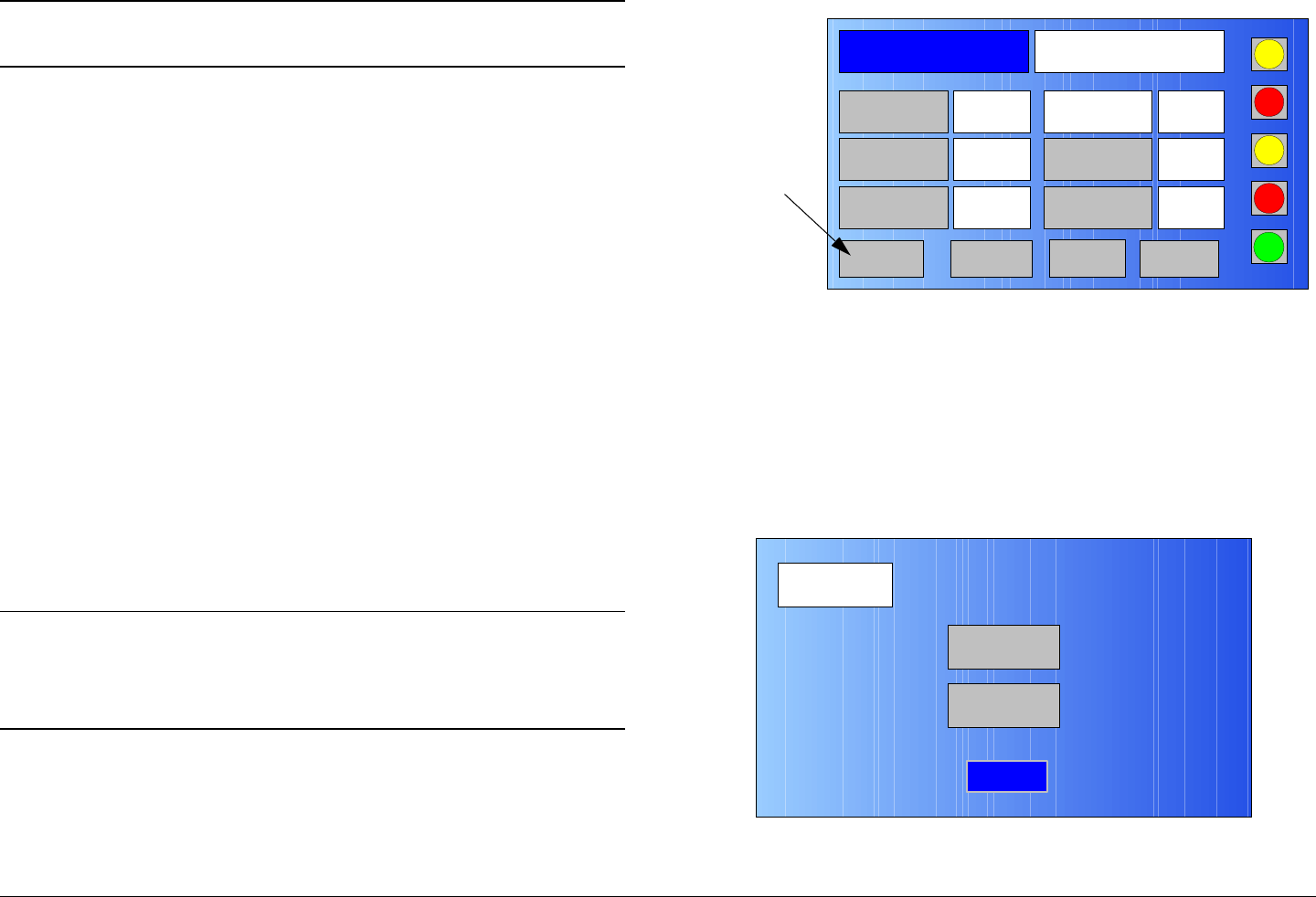
Advanced Operations 5-102MTX5000 User and Technical Manual
Note Procedures contained in this section may only be
performed in the Local mode.
The procedures required to save Preset configuration files
contained on your MTX5000 IDU to a USB flash drive, also
referred to as a thumb drive, memory stick, or memory device,
and to load Preset configuration files into your MTX5000 IDU are
contained in the following paragraphs. The procedures
contained in these paragraphs can only be performed in the
Local mode.
5.6.1 Restore Presets to Defaults
The procedure required to restore all custom Presets to the
factory default Presets is contained in the following steps.
Prior to performing this procedure, it is highly recommended that
you make a copy of any custom Preset files by performing “Save
Preset Configurations to a File” on page 5-104.
When performing the following steps, all custom Presets will be
deleted and only the factory default Presets will remain. In
addition, the password and IP address will also be changed to
the factory defaults.
Note In the following steps, the color LCD display option
buttons and pull-down menu options may be
selected using either the touch screen or the
function keys and the SEL key.
1. Verify the MTX5000 IDU is powered up. See
”Powering the MTX5000 System” on page 3-7.
2. Observe the Main screen is displayed. See Figure 5-
205.
Figure 5-205: Main Screen - Typical
3. Select the Main screen PA operation button for PA
Off, as required.
4. Select the L/R option button for L (local mode), as
required.
5. Select the Setup option button and observe the Setup
screen is displayed. See Figure 5-206.
Figure 5-206: Setup Screen
Channel 1 0Offset
Antenna Ant. Pol.Antenna1 H
RFU1
No RF
RF Band
Preset A Analog
4.83 & 5.8, 3MHz Vid Dev
RF Output XX
dBm
<- Status Setup Status ->
PA Off
SUM
ODU
IDU
RF
L/R
L
L
PA
Operation
Button
Setup
User
Main
Radio
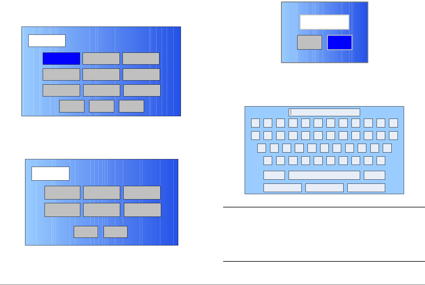
Advanced Operations 5-103MTX5000 User and Technical Manual
6. Select the Radio option button and observe the Radio
screen is displayed. See Figure 5-207.
Figure 5-207: Radio Screen
7. Select the Next option button and observe the
Radio - 2 screen is displayed. See Figure 5-208.
Figure 5-208: Radio - 2 Screen
8. Select the Restore Presets to Defaults option button
and observe the Are you sure? screen is displayed.
See Figure 5-209.
Radio
Back
Network Config Level Adjust Color Bars
Calibration
Time & Date
Change Pwd
System Info
License Key
Diagnostics
NextMain
Radio - 2
Back
Presets Option
Load Presets
from File
Remote Ctrl
Option
Save Presets
to File
PA State
Option
Restore Presets
to Defaults
Main
Figure 5-209: Are you sure? Screen
9. Select the Yes option button and observe the
keyboard screen is displayed. See Figure 5-210.
Figure 5-210: Keyboard Screen
Note When the Enter key is selected in the following
step, the MTX5000 IDU will perform an automatic
re-boot.
It will take approximately two minutes for the re-
boot to be complete.
No
Are you sure?
Yes
! @ # $ % ^ & * ( ) _ +
Q W E R T Y U I O P { }
A S D F G H J K L :
Z X C V B N M < > ?
Shift BS
Clear CancelEnter
“
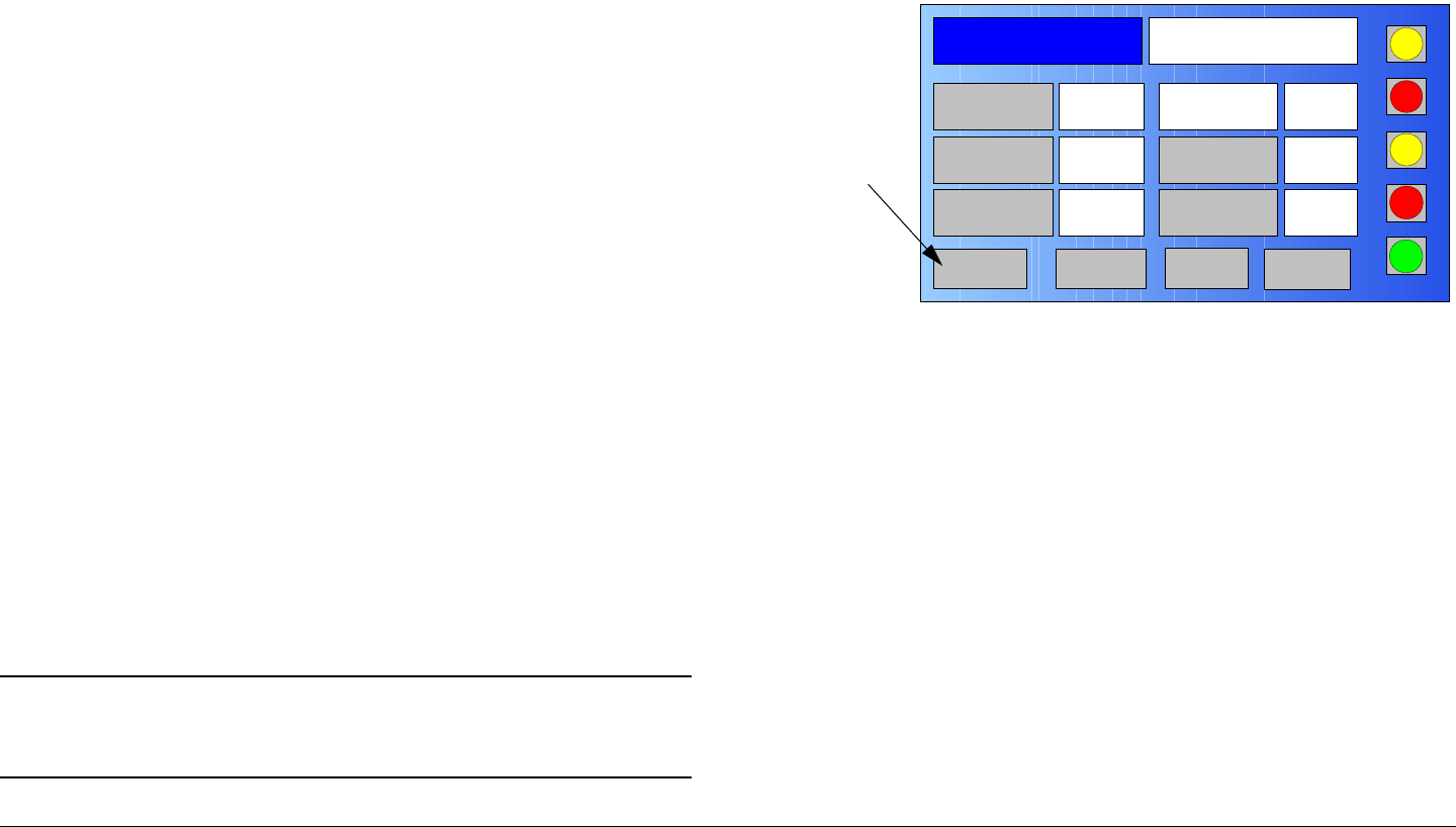
Advanced Operations 5-104MTX5000 User and Technical Manual
10. Enter your password, select the Enter key, observe
Please Wait is briefly displayed, the Operation Mode
screen is briefly displayed, and observe the MTX5000
IDU automatically re-boots.
11. Observe the Main page is displayed and the Preset
description text box indicates Default Presets.
Perform “Select Preset” on page 3-24 to select a
Preset, as required.
12. Perform “Local Mode Password Control” on page 5-3.
13. Perform “Set Network Addresses for Remote
Operation” on page 5-109.
5.6.2 Save Preset Configurations to a File
The procedure required to save the current Preset configuration
settings contained in your MTX5000 IDU to a USB memory
device is contained in the following steps. Saving the Preset
configuration settings to a USB memory device provides you
with a backup of all custom Presets that have been prepared and
saved in your MTX5000 IDU.
After the Preset configuration settings are saved to a USB
memory device, the USB memory device may be used to load
the same Preset settings into another MTX5000 IDU.
If the Preset settings are to be loaded into another MTX5000
IDU, the IDU must contain the same hardware configuration
options and must have the same licensed options as the IDU
from which the Preset configuration settings were saved to the
USB memory device.
Note In the following steps, the color LCD display option
buttons may be selected using either the touch
screen or the function keys and the SEL key.
1. Verify the MTX5000 IDU is powered up. See
”Powering the MTX5000 System” on page 3-7.
2. Observe the Main screen is displayed. See Figure 5-
211.
Figure 5-211: Main Screen - Typical
3. Select the Main screen PA operation button for PA
Off, as required.
4. Select the L/R option button for L (local mode), as
required.
5. Select the Setup option button and observe the Setup
screen is displayed. See Figure 5-212 on page 5-105.
Channel 1 0Offset
Antenna Ant. Pol.Antenna1 H
RFU1
No RF
RF Band
Preset A Analog
4.83 & 5.8, 3MHz Vid Dev
RF Output XX
dBm
<- Status Setup Status -> PA Off
SUM
ODU
IDU
RF
L/R
L
L
PA
Operation
Button
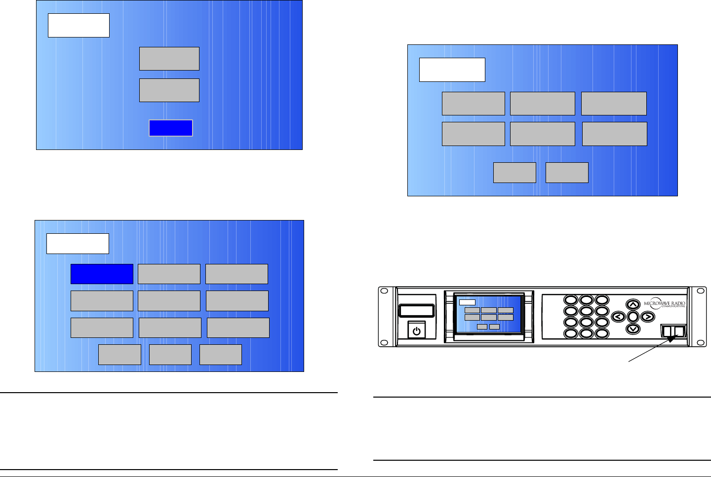
Advanced Operations 5-105MTX5000 User and Technical Manual
Figure 5-212: Setup Screen
6. Select the Radio option button and observe the Radio
screen is displayed. See Figure 5-213.
Figure 5-213: Radio Screen
Note In the following step, Load Presets from File and
Save Presets to File screen option buttons will be
inactive (greyed-out) until a USB memory device is
connected to the MTX5000 IDU front panel USB
2.0 connector.
Setup
User
Main
Radio
Radio
Back
Network Config Level Adjust Color Bars
Calibration
Time & Date
Change Pwd
System Info
License Key
Diagnostics
Next
Main
7. Select the Next option button and observe the Radio -
2 screen is displayed. See Figure 5-214.
Figure 5-214: Radio - 2 Screen
8. Connect a USB memory device to a USB-A to USB-B
adapter and connect the adapter to the IDU front panel
USB 2.0 connector. See Figure 5-215.
Figure 5-215: IDU Front Panel USB Connector
Note The Load Presets from File option button will not
be active in the following step if there is currently
no Preset setting configuration file on the USB
memory device.
Radio - 2
Back
Presets Option
Load Presets
from File
Remote Ctrl
Option
Save Presets
to File
PA State
Option
Restore Presets
to Defaults
Main
1
4
GHI
7
PQRS
*
Shift
2
ABC
5
JKL
8
TUV
0
3
DEF
6
MNO
9
WXYZ
SEL
#Space
MTX5000
USB 2.0
Connector
Radio - 2
Back
Preset s Option
Load Pres ets
from File
Remote Ctrl
Option
Save Presets
to File
PA State
Option
Restore Presets
to Defaults
Main

Advanced Operations 5-106MTX5000 User and Technical Manual
9. After a short delay, observe the Save Presets to File
option button is active (not greyed-out). See Figure 5-
216.
Figure 5-216: Preset File Screen - Typical
10. Select the Save Presets to File option button and
observe the Are you sure? screen appears. See
Figure 5-217.
Figure 5-217: Are you sure? Screen
11. Select the Yes option button and observe Are you
sure? changes to read Please wait.
12. After a short delay, observe the Please Wait! text box
disappears.
Radio - 2
Back
Presets Option
Load Presets
from File
Remote Ctrl
Option
Save Presets
to File
PA State
Option
Restore Presets
to Defaults
Main
No
Are you sure?
Yes
13. Disconnect the USB memory device and USB-A to
USB-B adapter from the IDU front panel USB 2.0
connector.
14. Select the Main option button and observe the Main
screen is displayed.
5.6.3 Load Preset Configurations from a File
The procedure required to load custom Preset configuration
settings from a USB memory device into your MTX5000 IDU is
contained in the following steps. This procedure may be used to
load custom Preset configuration settings from one MTX5000
IDU into another MTX5000 IDU using the USB memory device to
clone the IDU custom Preset configuration settings.
If the custom Preset settings are to be loaded into another
MTX5000 IDU, the IDU must contain the same hardware
configuration options and must have the same licensed options
as the IDU from which the custom Preset configuration settings
were saved to the USB memory device.
This procedure may also be used to recover custom Preset
configuration settings in the event you suspect that your
MTX5000 IDU internal software may have been corrupted during
normal operation.
Note In the following steps, the color LCD display option
buttons may be selected using either the touch
screen or the function keys and the SEL key.
1. Verify the MTX5000 IDU is powered up. See
”Powering the MTX5000 System” on page 3-7.
2. Observe the Main screen is displayed. See Figure 5-
218 on page 5-107.
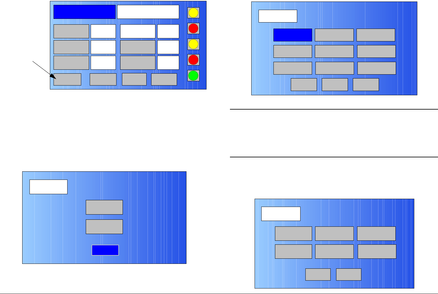
Advanced Operations 5-107MTX5000 User and Technical Manual
Figure 5-218: Main Screen - Typical
3. Select the Main screen PA operation button for PA
Off, as required.
4. Select the L/R option button for L (local mode), as
required.
5. Select the Setup option button and observe the Setup
screen is displayed. See Figure 5-219.
Figure 5-219: Setup Screen
6. Select the Radio option button and observe the Radio
screen is displayed. See Figure 5-220.
Channel 1 0Offset
Antenna Ant. Pol.Antenna1 H
RFU1
No RF
RF Band
Preset A Analog
4.83 & 5.8, 3MHz Vid Dev
RF Output XX
dBm
<- Status Setup Status ->
PA Off
SUM
ODU
IDU
RF
L/R
L
L
PA
Operation
Button
Setup
User
Main
Radio
Figure 5-220: Radio Screen
Note In the following step, the Load Presets from File
and Save Presets to File option buttons will be
inactive (greyed-out) until a USB memory device is
connected to the MTX5000 IDU front panel USB
2.0 connector.
7. Select the Next option button and observe the Radio -
2 screen is displayed. See Figure 5-221.
Figure 5-221: Radio - 2 Screen
Radio
Back
Network Config Level Adjust Color Bars
Calibration
Time & Date
Change Pwd
System Info
License Key
Diagnostics
Next
Main
Radio - 2
Back
Presets Option
Load Presets
from File
Remote Ctrl
Option
Save Presets
to File
PA State
Option
Restore Presets
to Defaults
Main
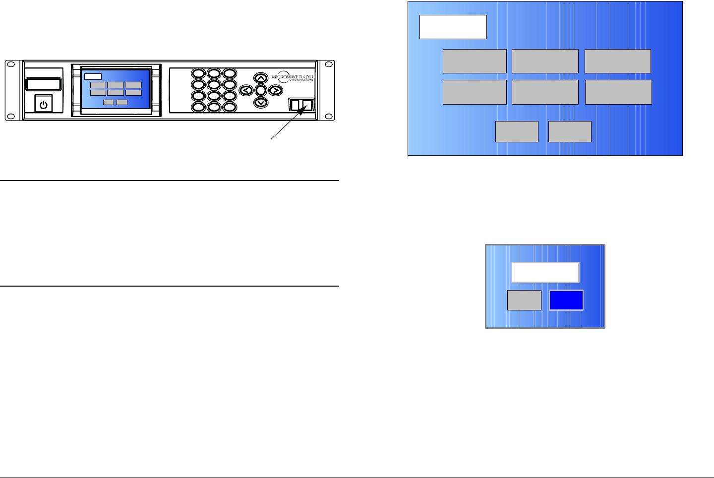
Advanced Operations 5-108MTX5000 User and Technical Manual
8. Connect a USB memory device to a USB-A to USB-B
adapter and connect the adapter to the IDU front panel
USB 2.0 connector. See Figure 5-222.
Figure 5-222: IDU Front Panel USB Connector
Notes Ensure your memory device contains the custom
Preset setting configuration file required.
The Load Presets from File option button will not
be active in the following step if there is no Preset
setting configuration file currently contained on the
USB memory device.
9. After a short delay, observe the Load Presets from
File option button is active (not greyed-out). See
Figure 5-223.
1
4
GHI
7
PQRS
*
Shift
2
ABC
5
JKL
8
TUV
0
3
DEF
6
MNO
9
WXYZ
SEL
#Space
MTX5000
USB 2.0
Connector
Radio - 2
Back
Presets Option
Load Presets
from File
Remote Ctrl
Option
Save Presets
to File
PA St ate
Option
Restore Presets
to Defaults
Main
Figure 5-223: Preset File Screen - Typical
10. Select the Load Presets from File option button and
observe the Are you sure? screen is displayed. See
Figure 5-224.
Figure 5-224: Verification Screen
11. Select the Yes option button and observe the Please
Wait! message box is displayed. See Figure 5-225 on
page 5-109.
Radio - 2
Back
Presets Option
Load Presets
from File
Remote Ctrl
Option
Save Presets
to File
PA State
Option
Restore Presets
to Defaults
Main
No
Are you sure?
Yes

Advanced Operations 5-109MTX5000 User and Technical Manual
Figure 5-225: Please Wait Message Box
12. When the Please Wait! message box disappears, go
to the following step.
13. Disconnect the USB memory device and USB-A to
USB-B adapter from the IDU front panel USB 2.0
connector.
14. Select the Main option button and observe the Main
screen is displayed.
5.7 Set Network Addresses for
Remote Operation
The steps required to set the radio network, file network, and
trap configuration addresses are contained in the following
procedures. These procedures may only be performed in the
Local mode of operation.
CAUTION Avoid damage to the color LCD display
panel!
The color LCD display panel touch screen
may be damaged if a sharp, hard-pointed
object, such as a pencil or a pen, is used to
select the displayed options.
No
Please Wait!
Yes
Touch screen options must only be selected
using your fingers, a soft-pointed stylus, or
the front panel function keys.
Damage to the color LCD display panel
caused by using a hard-pointed object or
other misuse may void your warranty on the
MTX5000 IDU.
The procedure required to set the network addresses to allow
operation of your MTX5000 System from a remote location is
contained in the following steps.
Before proceeding with this procedure, you must obtain
valid Radio IP, Subnet Mask, Gateway, and DNS Server
addresses from your Network Administrator. All addresses
must be properly entered into your MTX5000 IDU before you can
operate your MTX5000 System from a remote location.
It is important that the MTX5000 must not be transmitting
when this procedure is performed.
When updating the software in the IDU, you must observe the
following CAUTIONS to avoid corrupting software.
CAUTION Do not power down the MTX5000 system
when the software update progress bar is
displayed, as the software update can
become corrupted.
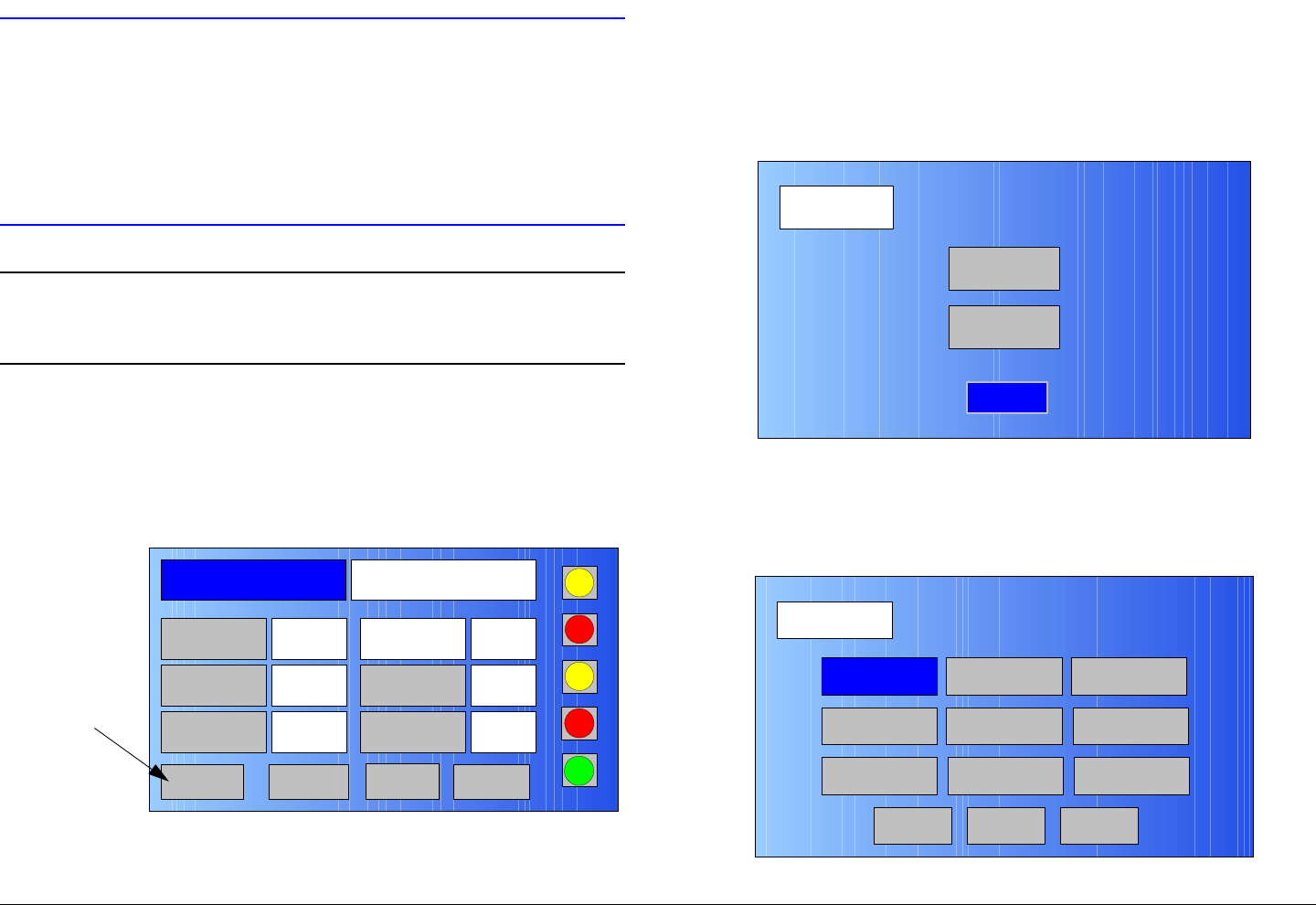
Advanced Operations 5-110MTX5000 User and Technical Manual
CAUTION Do not attempt to perform this procedure
while the MTX5000 system is actively
transmitting.
Attempts to perform this procedure when
the system is transmitting will interrupt
broadcast operations.
Note In the following steps, option buttons may be
selected using either the touch screen or the
function keys and the SEL key.
1. Verify the MTX5000 IDU is powered up. See
”Powering the MTX5000 System” on page 3-7.
2. Observe the Main screen is displayed. See Figure 5-
226.
Figure 5-226: Main Screen - Typical
3. Select the Main screen PA operation button for PA
Off, as required.
Channel 1 0Offset
Antenna Ant. Pol.Antenna1 H
RFU1
No RF
RF Band
Preset A Analog
4.83 & 5.8, 3MHz Vid Dev
RF Output XX
dBm
<- Status Setup Status ->
PA Off
SUM
ODU
IDU
RF
L/R
L
L
PA
Operation
Button
4. Select the L/R option button for L (local mode), as
required.
5. Select the Setup option button and observe the Setup
screen is displayed. See Figure 5-227.
Figure 5-227: Setup Screen
6. Select the Radio option button and observe the Radio
screen is displayed. See Figure 5-228.
Figure 5-228: Radio Screen
Setup
User
Main
Radio
Radio
Back
Network Config Level Adjust Color Bars
Calibration
Time & Date
Change Pwd
System Info
License Key
Diagnostics
Next
Main
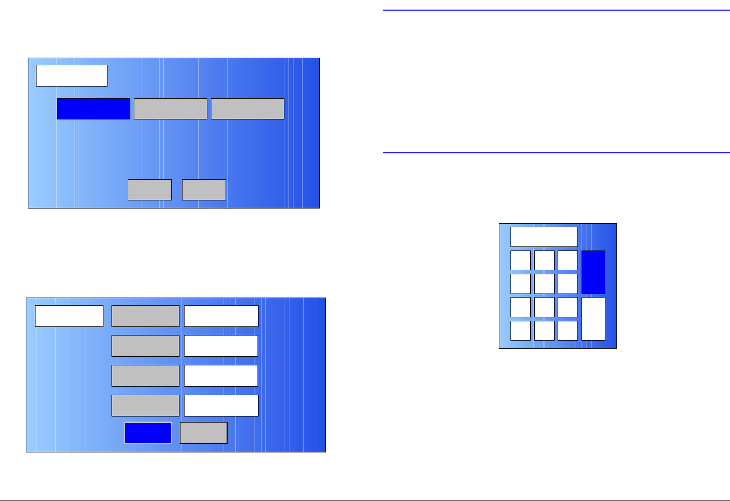
Advanced Operations 5-111MTX5000 User and Technical Manual
7. Select the Network Config option button and observe
the Network screen is displayed. See Figure 5-229.
Figure 5-229: Network Config Screen
8. Select the Radio Network option button and observe
the Radio Network screen is displayed. See
Figure 5-230.
Figure 5-230: Radio Network Screen - Typical
Network Config
Radio Network
Back
File Network
Main
Trap Config
Radio Network IP Address
Back
10.4.3.213
Subnet Mask
Gateway
DNS Server
255.255.0.0
10.4.1.1
10.4.1.21
Main
CAUTION In the following steps, the IP Address,
Subnet Mask, Gateway, and DNS Server
addresses must all be entered correctly.
If the addresses don’t match the
configuration of the network to which the
MTX5000 IDU is connected, the MTX5000
IDU will not be detected and cannot be used
from a remote location.
9. Select the IP Address option button and observe the
numeric keypad is displayed. See Figure 5-231.
Figure 5-231: Numeric Keypad
10. Enter the IP address, select the ENT key, and observe
the Radio Network screen is displayed.
11. Select the Subnet Mask option button and observe
the numeric keypad is displayed.
12. Enter the Subnet Mask address, select the ENT key,
and observe the Radio Network screen is displayed.
13. Select the Gateway option button and observe the
numeric keypad is displayed.
123
ESC
0
4
7
5 6
8 9
CLR 0ESC
ENT
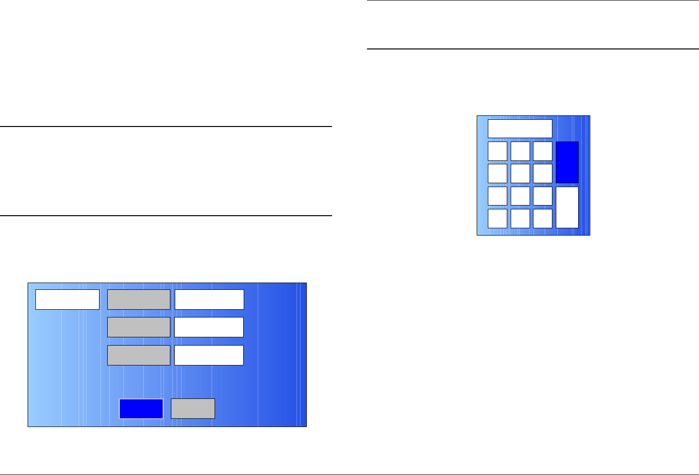
Advanced Operations 5-112MTX5000 User and Technical Manual
14. Enter the Gateway address, select the ENT key, and
observe the Radio Network screen is displayed.
15. Select the DNS Server option button and observe the
numeric keypad is displayed.
16. Enter the DNS Server address, select the ENT key,
and observe the Radio Network screen is displayed.
17. Select the Back option button and observe the
Network Config screen is displayed.
Note If you do not have the IP option installed, the File
Network option button will be inactive (greyed-out)
in the following step.
If the File Network option button is inactive, go to
step 25.
18. Select the File Network option button and observe the
File Network screen is displayed. See Figure 5-232.
Figure 5-232: File Network Screen - Typical
File Network IP Address
Back
Subnet Mask
Gateway
Main
Note When entering File Network addresses in the
following steps, the addresses cannot be the same
as the Radio Network addresses.
19. Select the IP Address option button and observe the
numeric keypad is displayed. See Figure 5-233.
Figure 5-233: Numeric Keypad
20. Enter the IP address, select the ENT key, and observe
the File Network screen is displayed.
21. Select the Subnet Mask option button and observe
the numeric keypad is displayed.
22. Enter the Subnet Mask address, select the ENT key,
and observe the File Network screen is displayed.
23. Select the Gateway option button and observe the
numeric keypad is displayed.
24. Enter the Gateway address, select the ENT key, and
observe the File Network screen is displayed.
25. Select the Back option button and observe the
Network Config screen is displayed.
26. Select the Trap Config option button and observe the
Trap Config screen is displayed. See Figure 5-234 on
page 5-113.
1 2 3
ESC
0
4
7
5 6
8 9
CLR 0ESC
ENT

Advanced Operations 5-113MTX5000 User and Technical Manual
Figure 5-234: Trap Config Screen - Typical
27. Select the Dest. Address option button and observe
the numeric keypad is displayed.
28. Enter the destination address, select the ENT key, and
observe the Trap Config screen is displayed.
29. Select the Port # option button and observe the
numeric keypad is displayed.
30. Enter the port number required, select the ENT key,
and observe the Trap Config screen is displayed.
31. Select the Main option button and observe the Main
screen is displayed.
32. Press the front panel power switch to off, wait a
minimum of 10 seconds, and press the power switch
to on. When the Main screen is displayed, go to the
following step.
Trap Config Dest. Address
Back
192.168.1.2
Port # 162
Main
Notes The following steps verify the correct IP Address,
Subnet Mask, Gateway, and DNS Server
addresses have been correctly entered by verifying
that you can connect to your MTX5000 System
from a remote PC.
If the addresses have not been correctly entered,
you will not be able to connect from a remote PC.
Repeat from step 5 to verify or correct addresses.
If all addresses have been correctly entered and
you cannot connect from a remote PC, contact
your Network Administrator for assistance.
33. Verify your MTX5000 IDU ETHERNET connector is
properly connected to your network.
34. At the remote PC, open your web browser, enter the IP
address for your MTX5000 IDU, and press the PC
keyboard Enter key.
35. After a short delay, observe the remote screen display
appears on your PC. See Figure 5-235 on page 5-
114.
Advanced Operations 5-114MTX5000 User and Technical Manual
Figure 5-235: Remote Screen Display - Typical
36. Perform “Select Local/Remote Operation Mode” on
page 3-20 and set the MTX5000 for remote mode
operation.
37. Verify operations can be performed from a remote PC
by performing any selected procedure contained in
“Remote Location Operations” on page 3-67.
38. When remote operations are verified, select the
MTX5000 IDU Main screen L/R option button to
change it to L (local mode), as required.
5.8 Firmware Update
CAUTION Avoid damage to the color LCD display
panel when performing the following
procedures!
The color LCD display panel touch screen
may be damaged if a sharp, hard-pointed
object, such as a pencil or a pen, is used to
select the displayed options.
Touch screen options must only be selected
using your fingers, a soft-pointed stylus, or
the front panel function keys.
Damage to the color LCD display panel
caused by using a hard-pointed object or
other misuse may void your warranty on
the MTX5000 IDU.
The procedure required to update firmware in your MTX5000
Indoor Unit (IDU) is contained in the following steps. Firmware
updates must be obtained from the factory. The updates will be
installed in the MTX5000 Indoor Unit (IDU) using a USB flash
drive. The USB flash drive, also referred to as a thumb drive,
memory stick, or memory device is connected to the MTX5000
IDU front panel USB 2.0 connector using a USB-A to USB-B
adapter.
The firmware update procedure can be performed with the
MTX5000 IDU disconnected from the system or can be
performed when the IDU is installed in its normal rack-mounted
position.
It is important that the MTX5000 must not be transmitting
when this procedure is performed.
When updating the firmware in the IDU, you must observe the
following CAUTIONS to avoid corrupting firmware.

Advanced Operations 5-115MTX5000 User and Technical Manual
CAUTION Do not power down the MTX5000 system
when the firmware update progress bar is
displayed, as the firmware update can
become corrupted.
CAUTION Do not attempt to perform the IDU firmware
update while the MTX5000 system is
actively transmitting.
Attempts to program firmware updates into
the IDU when the system is transmitting will
interrupt broadcast operations.
Note In the following steps, option buttons may be
selected using either the touch screen or the
function keys and the SEL key.
1. Verify the MTX5000 system is powered up per
“Powering the MTX5000 System” on page 3-7.
2. Observe the Main screen is displayed. See Figure 5-
236.
Figure 5-236: Main Screen - Typical
3. Select the Main screen PA operation button for PA
Off, as required.
4. Select the L/R option button for L (local mode), as
required.
5. Connect the USB memory device containing the
software update to a USB-A to USB-B adapter and
connect the adapter to the IDU front panel USB 2.0
connector. See Figure 5-237.
Figure 5-237: IDU Front Panel USB Connector
6. After a short delay, observe the Firmware Update
screen is displayed. See Figure 5-238 on page 5-116.
Channel 1 0Offset
Antenna Ant. Pol.Antenna1 H
RFU1
No RF
RF Band
Preset A Analog
4.83 & 5.8, 3MHz Vid Dev
RF Output XX
dBm
<- Status Setup Status -> PA Off
SUM
ODU
IDU
RF
L/R
L
L
PA
Operation
Button
1
4
GHI
7
PQRS
*
Shift
2
ABC
5
JKL
8
TUV
0
3
DEF
6
MNO
9
WXYZ
SEL
#Space
MTX5000
USB 2.0
Connector
Channel 1 0Offset
Antenna Ant. Pol.Antenna1 H
RFU1
No RF
RF Band
Pres et A Analog
4.83 & 5.8, 3MHz Vid Dev
RF Output XX
dBm
<- Status Setup Status -> PA Off
SUM
ODU
IDU
RF
L/R
L
L
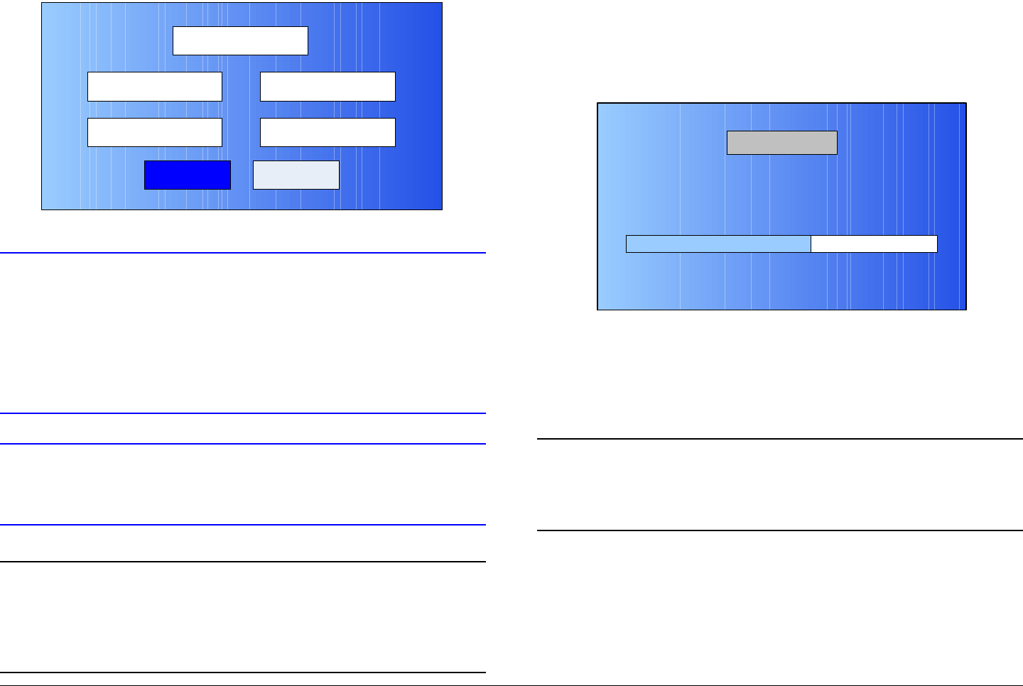
Advanced Operations 5-116MTX5000 User and Technical Manual
Figure 5-238: Firmware Update Screen - Typical
CAUTION When the Update option button is selected
in the following step, a progress bar will be
displayed during the update process.
Do not power the MTX5000 down for any
reason while the progress bar is displayed,
as the firmware upgrade will be corrupted.
CAUTION To avoid corruption of the firmware update,
do not remove the USB flash drive until the
firmware update process is complete.
Notes If the Current Version and New Version are
different, go to step 7.
If the Current Version and New Version are
identical, go to step 10.
Firmware Update
Update Cancel
Current Version
New Version V.0.4.Y
V.0.3.X
7. Select the Update option button and observe the
Firmware Update screen is displayed and a progress
bar is displayed during the update process. See
Figure 5-239.
Figure 5-239: Firmware Update Screen - Typical
8. When the firmware update is complete, the IDU will re-
boot, the Main screen will be displayed, and the
Firmware Update screen will be displayed after a
short delay.
Note In the following step, if the versions shown in the
Firmware Update screen Current Version and
the New Version text boxes are identical, the
firmware update was successful.
9. Observe the Current Version and New Version text
boxes indicate the same version. See Figure 5-240 on
page 5-117.
60 %
Firmware Update in Progress
DO NOT POWER OFF RADIO UNTIL UPDATE COMPLETED!
Please Wait
Firmware Update
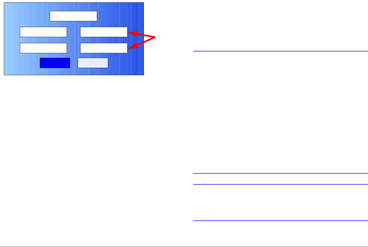
Advanced Operations 5-117MTX5000 User and Technical Manual
Figure 5-240: Firmware Update Screen - Typical
10. Disconnect the USB memory device and adapter from
the IDU front panel USB 2.0 connector.
11. Select the Cancel option button, and observe the
Main screen is displayed after a short delay.
12. Press the power switch to off, wait 10 seconds
minimum, and press the power switch to on.
5.9 License Manager
This section describes how to add factory licensed options to
your MTX5000 IDU. Only licensed options applicable to the
hardware options contained in your MTX5000 IDU can be
installed in your radio.
Your MTX5000 IDU does not have to be returned to the factory
to add licensed options applicable to your MTX5000 IDU
configuration. The internal software contains a license manager
feature that allows you to add licensed options to your IDU that
were not initially ordered with your radio.
The license manager procedure can be performed with the
MTX5000 IDU disconnected from the system or can be
Firmware Update
Update Cancel
Current Version
New Version V.0.4.Y
V.0.4.Y
performed when the IDU is installed in its normal rack-mounted
position.
It is important, however, that the MTX5000 must not be
transmitting when these procedures are performed.
When performing procedures contained in this section, you must
observe the following CAUTIONS to avoid corrupting software.
CAUTION Avoid damage to the color LCD display
panel!
The color LCD display panel touch screen
may be damaged if a sharp, hard-pointed
object, such as a pencil or a pen, is used to
select the displayed options.
Touch screen options must only be selected
using your fingers, a soft-pointed stylus, or
the front panel function keys.
Damage to the color LCD display panel
caused by using a hard-pointed object or
other misuse may void your warranty on
the MTX5000 IDU.
CAUTION Do not power down the MTX5000 system
when the software update progress bar is
displayed, as the software update can
become corrupted.
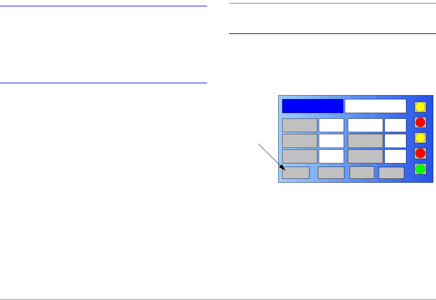
Advanced Operations 5-118MTX5000 User and Technical Manual
CAUTION Do not attempt to perform this procedure
while the MTX5000 system is actively
transmitting.
Attempts to program license manager
features into the IDU when the system is
transmitting will interrupt broadcast
operations and may corrupt the software.
In order to add a licensed option to your MTX5000 IDU, you
must obtain a license key applicable to the option required.
This license key is available only from MRC. Your IDU must
also contain the hardware applicable to the licensed option.
When ordering a license key from MRC, you must provide MRC
with both the serial number of your MTX5000 IDU and the serial
number of the main circuit board in the IDU. The IDU serial
number is located on the right-hand side of the chassis.
To identify the electronic serial number of the IDU Encoder/
Modulator board, perform step 1 thru step 7 of the following
procedure and record the serial number listed in the Serial No.
text box.
The procedure required to install a new licensed option, after
obtaining the license key from MRC, is contained in the following
steps. This procedure is generic and can be used to install all
licensed options in your MTX5000 IDU. Each licensed option
contained in your MTX5000 IDU requires an individual license
key.
Note In the following steps, the color LCD display option
buttons may be selected using either the touch
screen or the function keys and the SEL key.
1. Verify the MTX5000 IDU is powered up. See
”Powering the MTX5000 System” on page 3-7.
2. Observe the Main screen is displayed. See Figure 5-
241.
Figure 5-241: Main Screen - Typical
3. Select the Main screen PA operation button for PA
Off, as required.
4. Select the L/R option button for L (local mode), as
required.
5. Select the Main screen Setup option button and
observe the Setup screen is displayed. See Figure 5-
242 on page 5-119.
Channel 1 0Offset
Antenna Ant. Pol.Antenna1 H
RFU1
No RF
RF Band
Preset A Analog
4.83 & 5.8, 3MHz Vid Dev
RF Output XX
dBm
<- Status Setup Status -> PA Off
SUM
ODU
IDU
RF
L/R
L
L
PA
Operation
Button
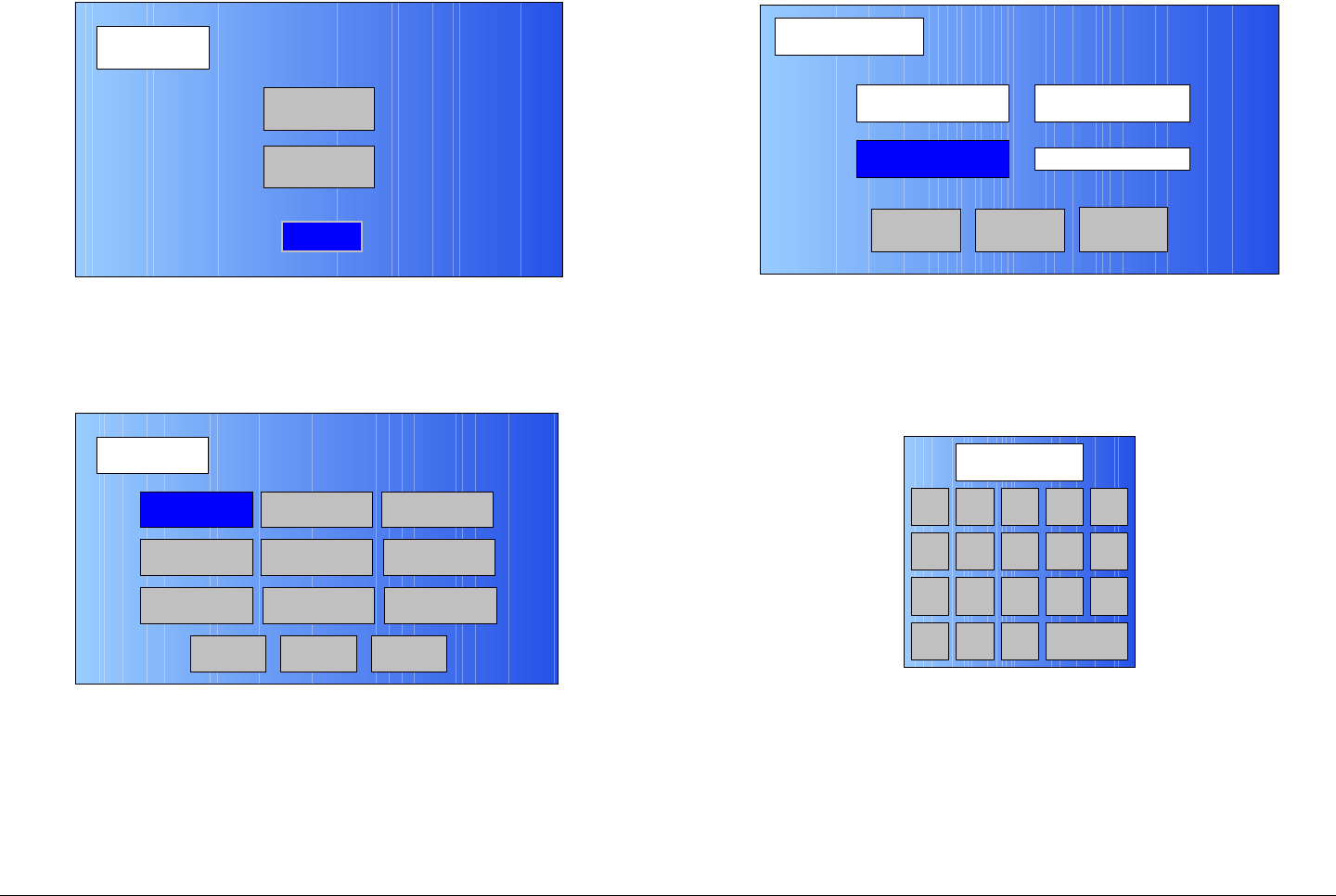
Advanced Operations 5-119MTX5000 User and Technical Manual
Figure 5-242: Setup Screen
6. Select the Radio option button and observe the Radio
screen is displayed. See Figure 5-243
Figure 5-243: Radio Screen
7. Select the License Key option button and observe the
License Setup screen is displayed. See Figure 5-
244.
Setup
User
Main
Radio
Radio
Back
Network Config Level Adjust Color Bars
Calibration
Time & Date
Change Pwd
System Info
License Key
Diagnostics
Next
Main
Figure 5-244: License Setup Screen - Typical
8. Select the License Key option button and observe the
alphanumeric keyboard is displayed. See Figure 5-
245.
Figure 5-245: Alphanumeric Keyboard
9. Enter the 12-character license key obtained from
MRC, select the ENT key, and observe the License
Setup screen is displayed. See Figure 5-246 on
page 5-120.
License Setup
Cancel
Serial No. 123X45Y6
License Key
Submit Main
1 2 3
0
4
7
5 6
8 9
DEL CAN 0ENT
A D
B E
C F

Advanced Operations 5-120MTX5000 User and Technical Manual
Figure 5-246: License Setup Screen - Typical
Notes When the Submit option button is selected in the
following step, the licensed option will be enabled if
the correct license key was entered.
If a typing error occurred when the license key was
entered, no verification or error message will be
displayed. Incorrect keys will be stored in the IDU
memory.
If the licensed option does not perform as expected
during normal operation, repeat from step 7 to
enter the correct license key.
10. Select the Submit option button.
11. Select the Main option button and observe the Main
screen is displayed.
License Setup
Main
Serial No. 123ABCD8
License Key
Submit Cancel
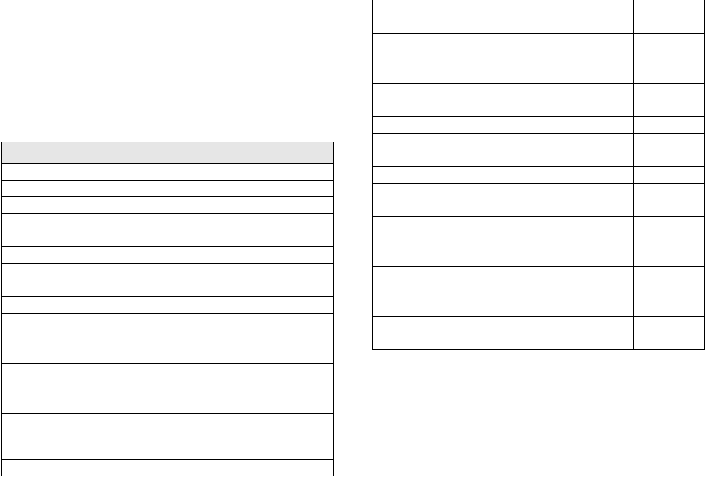
6
Installation 6-1MTX5000 User and Technical Manual
Installation
6.1 Chapter Overview
This chapter describes how to unpack and install your MTX5000
Transmitter System (MTX5000). The MTX5000 system consists
of the MTX5000 Indoor Unit (IDU) and Outdoor Unit (ODU), also
referred to as the RF Unit. The topics covered in this chapter are
as follows:
Topic Page
Unpacking 6-1
Initial Inspection 6-2
Damage in Shipment 6-2
Installing the MTX5000 IDU 6-2
Site Preparation 6-2
Mounting the MTX5000 IDU 6-3
Power Connections 6-4
Power Requirements 6-4
Power Supply and Distribution 6-4
Grounding 6-5
Defining the Wiring Harness 6-5
Steps to Define the Harness 6-5
Select the Type of RF/Power Cabling 6-5
Select the Function Cables Required 6-7
Determine the Size of Harness Required 6-9
Cabling Requirements 6-9
MTX5000 System Type “N” Connector
Interface 6-11
MTX5000 System TNC Connector Interface 6-12
6.2 Unpacking
Each MTX5000 is shipped assembled, wired, and factory tested.
Each unit is packaged in appropriate shipping containers.
Here are some tips to help you with unpack your new equipment:
• Unpack the equipment carefully to avoid accidental
damage.
Installing the Fabricated Harness 6-13
Installing the Outdoor Unit 6-13
Site Preparation 6-14
Mounting the ODU 6-14
Making the Connections 6-15
Mast Top Connections 6-16
IDU Connections 6-16
Wayside Data Connections 6-24
Wayside Connections 6-24
Compatibility 6-24
Audio Connections 6-24
Audio Inputs 6-24
Analog Audio Inputs 6-25
Digital Audio Inputs 6-25
ODU Power 6-26
Remote Control Operations 6-26
Powering Up 6-27
Checks Before Power-Up 6-27
Initial Power-Up 6-27
Power Down 6-29
Product Modifications 6-29

Installation 6-2MTX5000 User and Technical Manual
• Be sure to locate all parts and accessories.
• Verify that the items shipped agree with those listed on
the packing list.
• DO NOT discard the container(s) or packing material until
you have inspected the equipment and are sure there is
no shipping damage. The container(s) and packing must
be available in the event that a damage claim needs to be
filed with the shipping carrier.
6.3 Initial Inspection
After the equipment is unpacked, we recommend you inspect it
using the following checklist:
• Check for any dents or scratches.
• Check that the equipment is clean and dry.
• Check that no cables or connectors are broken, damaged,
or loose.
• Check that no switch, keypad, or function keys are
broken, damaged, or loose.
• Check that the LCD display has not been damaged.
6.4 Damage in Shipment
Should any damage be discovered after unpacking the unit, use
the following procedure:
• Immediately file a claim with the shipping carrier.
• Forward a copy of the damage report to MRC Customer
Service.
• Contact MRC Customer Service to determine the
disposition of the equipment.
6.5 Installing the MTX5000 IDU
For mobile applications, the MTX5000 is typically mounted in a
bulkhead or compartment 19-inch (48.3 cm) rack and the cabling
is permanently installed. Power comes from the mobile power
source.
6.5.1 Site Preparation
The following requirements are designed to make initial
installation easier and to allow room for future access and
servicing.
Equipment Rack The MTX5000 mounts into the mounting rails
of a standard 19-inch (48.3 cm) equipment rack. It occupies 2
rack units (2RU) of height.
• Make certain the rack and mounting rails are strong and
rigid enough to support the MTX5000 and the rest of the
equipment in the rack.
• It is recommended that a rack mount shelf be installed in
the back of the rack to help support the MTX5000 during
the high stresses of vehicle vibration.
• The rack should be securely attached to a solid surface
such as a floor or wall to prevent movement or tipping
over.
• Position the rack to allow easy access to the front and
rear of the equipment.
• Be sure to allow room behind the equipment rack for the
many cables required. The cables should not be pressed
against the rear of the equipment when closing doors.
This will stress the cables and may shorten their life.
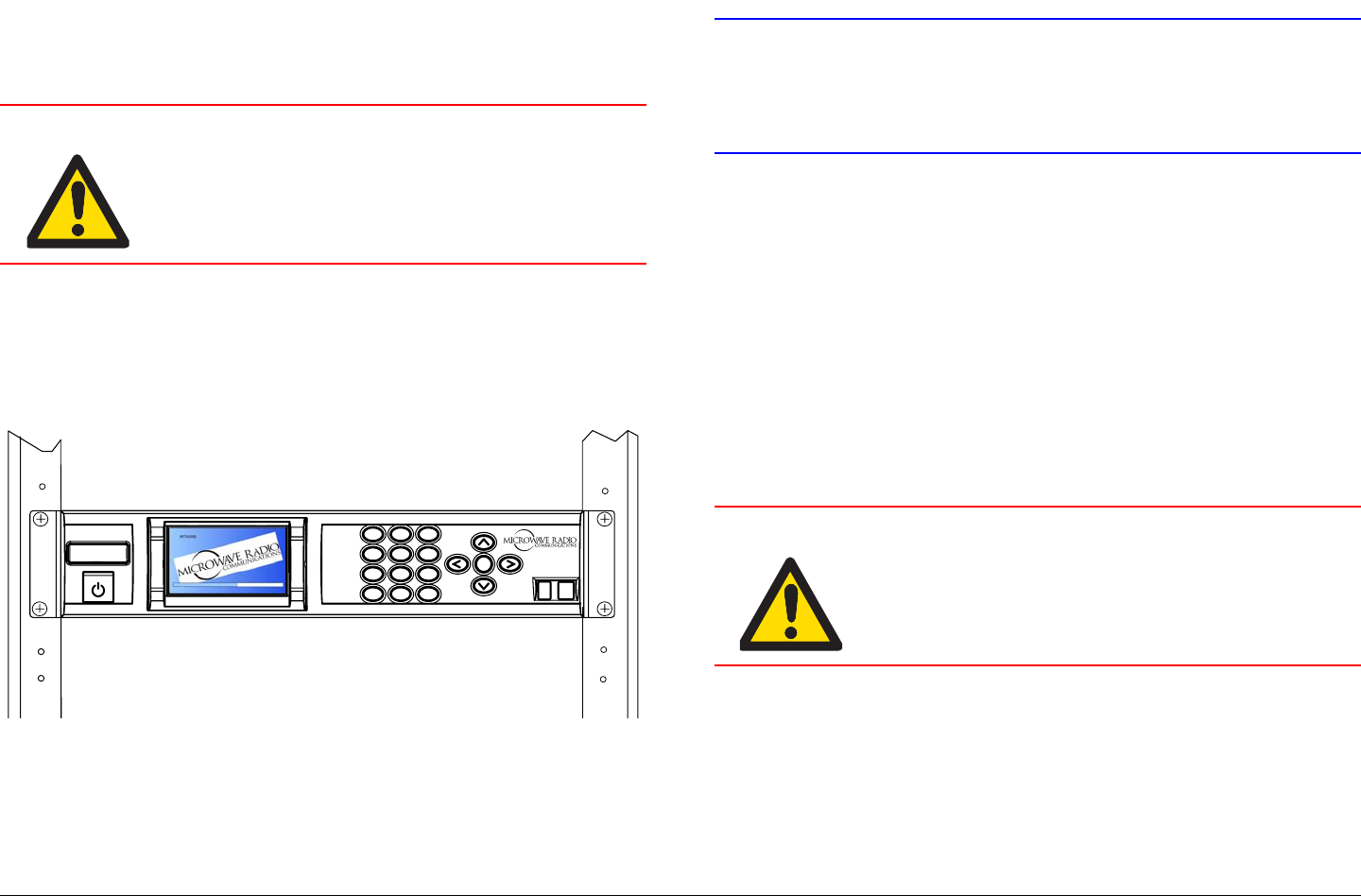
Installation 6-3MTX5000 User and Technical Manual
6.5.2 Mounting the MTX5000 IDU
Mounting the MTX5000 IDU into an equipment rack is easier if
one person holds the unit while another person installs the
mounting screws.
WARNING Follow instructions carefully.
Exercise care to avoid equipment damage
or personnel injury.
1. Lift the MTX5000 IDU into place, lining up its mounting
holes with the holes in the rack mounting rails. See
Figure 6-1.
Figure 6-1: MTX5000 IDU Mounting
2. Install the two bottom screws first. Use lock washers
to prevent loosening. Tighten securely.
3. Install the top two screws. Use lock washers to
prevent loosening. Tighten securely.
1
4
GHI
7
PQRS
*
Shift
2
ABC
5
JKL
8
TUV
0
3
DEF
6
MNO
9
WXYZ
SEL
#Space
MTX5000
Ventilation
CAUTION Temperatures inside a closed mounting
area can be significantly higher than the
ambient temperature. Always allow
adequate ventilation.
• If possible, install the MTX5000 IDU in a climate-
controlled area.
• Installation should allow adequate air flow around the
equipment. Air flow should be circulated and mixed with
room air, not trapped in a closed space.
• When mounting the MTX5000 IDU in an enclosed rack
with other equipment, it is good practice to allow spaces
at the top and bottom of the rack, and to fill those spaces
with grillwork instead of blank panels.
Moisture
WARNING Indoor equipment is not designed to
withstand water or moisture. If water does
penetrate the chassis, it could cause
equipment damage and/or create a safety
hazard.
• Locate the equipment in an area protected from dripping
water or excessive humidity.
Cabling
In mobile installations, wiring is subject to extremes of
temperature, humidity, and vibration. MRC recommends the
following general practices be performed in all installations.
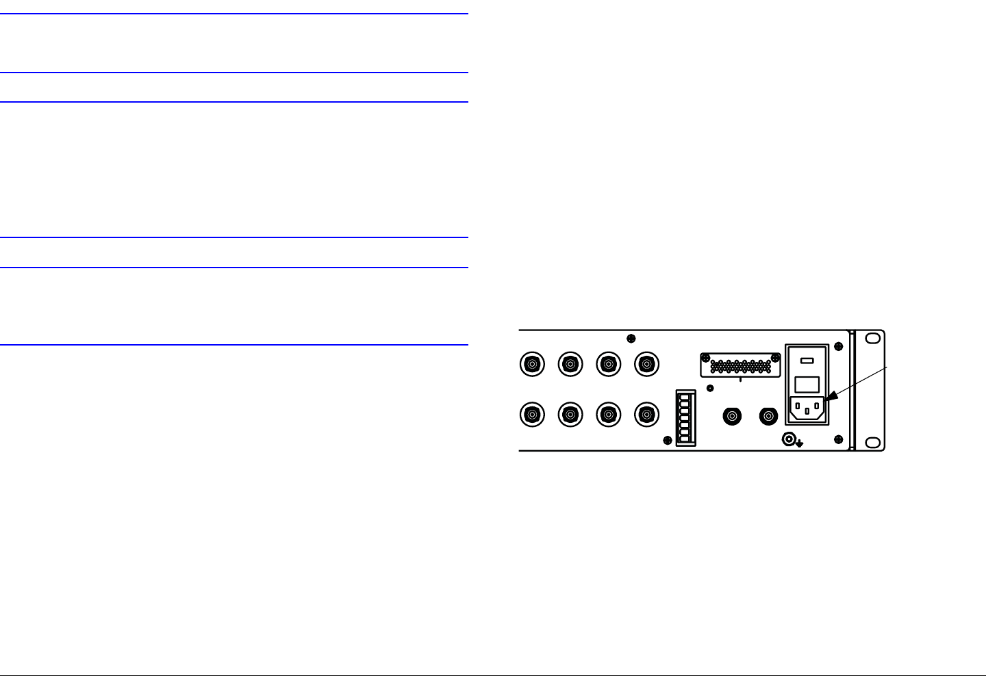
Installation 6-4MTX5000 User and Technical Manual
CAUTION Be sure the power being supplied matches
the power required by the equipment.
CAUTION Power supply cords and cables must be
protected. Do not run cords where they can
be walked upon. Protect cables against
pinching and chafing. Pay special attention
to locations where the cables enter or exit
an enclosure or make a sharp bend.
CAUTION Ensure that the electrical supply is protected
by over current protection devices, as
required by the applicable electrical codes.
• Secure all cables at close intervals along their entire
lengths.
• Protect the cabling with additional sheathing or padding
anywhere it passes through a hole or lays against an
obstruction.
• Provide flex relief at any location where the cable must
change direction sharply, to maintain a smooth bend and
prevent kinking.
• Provide strain relief at each connector to absorb any
pulling forces on the cable and prevent damage to the
connector.
6.6 Power Connections
6.6.1 Power Requirements
The MTX5000 has the following power requirements.
Supply Voltage: 120/240 VAC, 50/60 Hz
IDU Power Consumption: 40 Watts Nominal
Standard ODU Power Consumption: 65 Watts Nominal
High Power ODU Power Consumption: 80 Watts Nominal
6.6.2 Power Supply and Distribution
AC power is supplied externally, from the mobile power source.
Power is distributed to the MTX5000 through the rear panel AC
POWER IN connector. See Figure 6-2.
Figure 6-2: AC POWER IN Connector
Power Connections MRC supplies an AC power cable with
each MTX5000.
Additional Powering Notes Check the electrical supply to be
sure it can provide all the power needed at the site without
overloading. Power ratings for equipment can be found on a
rating plate, usually on the rear panel.
IF MON
AC-3
S
MPTE 302
ASI 1 HD-SDI ASI 2
IF IN VID MON SDI/ASI
ANT
CONTROL
RFU POWER OUT
RFU 1 RFU 2
H
V
LCP
ANT2
BAND2
GND
+
- - + +
- - + +
12
POWER IN
POWER IN
Connector

Installation 6-5MTX5000 User and Technical Manual
CAUTION Be sure the power being supplied matches
the power required by the equipment.
CAUTION Power supply cords and cables must be
protected. Do not run cords where they can
be walked upon. Protect cables against
pinching and chafing. Pay special attention
to locations where the cables enter or exit an
enclosure or make a sharp bend.
CAUTION Ensure that the electrical supply is protected
by overcurrent protection devices as required
by the applicable electrical codes.
6.7 Grounding
CAUTION Be sure the equipment grounding follows
applicable electrical codes.
CAUTION Never modify a grounded power plug to
connect to an ungrounded receptacle.
• The MTX5000 must be connected to the common ground
on the installation. This common ground is often the
vehicle ground.
• The ground wire should be as short as possible, and follow
the straightest path possible.
6.8 Defining the Wiring Harness
This section describes how to define the wiring harness that
connects the MTX5000 IDU to ODU. The wiring harness
contains RF/Power cables and function cables.
Supplying main power to the MTX5000 IDU is covered in
Section 6.6 on page 6-4.
6.8.1 Steps to Define the Harness
Perform the following steps to define the wiring harness between
the IDU and the ODU.
1. Select the type of RF/power cabling required. See
”Select the Type of RF/Power Cabling” .
2. Select the function cables required. See Section 6.8.3
on page 6-7.
3. Determine the size of the wiring harness required.
See Section 6.8.4 on page 6-9.
4. When the wiring harness is fabricated, go to “Installing
the Fabricated Harness” on page 6-13.
6.8.2 Select the Type of RF/Power Cabling
The first step is to determine what type of RF and DC power
cabling you will be using to connect the IDU to the ODU. There
are three different options:
• Triax connectors (RF, control, and DC power in one
cable). See Figure 6-3 on page 6-6.
• Type “N” connectors (RF and control on one cable, DC
power in another cable). See Figure 6-4 on page 6-7.
• TNC connectors (RF and control in one cable, DC power
in another cable). See Figure 6-4 on page 6-7.
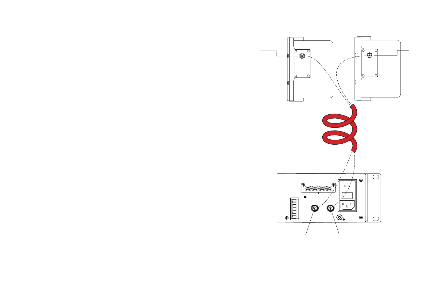
Installation 6-6MTX5000 User and Technical Manual
The MTX5000 system may be ordered with Triax, Type “N”, or
TNC cable connectors. Existing installations may use Triax,
Type “N”, or TNC cabling. ‘
Special Note - Triax Installations Over time, flexing and
vibration can cause the connections inside the Triax connector to
deteriorate, leading to high resistance in the DC circuit paths.
This, in turn, can cause erratic and intermittent problems with the
MTX5000 system.
MRC recommends you avoid this possibility by performing the
following:
• Install the Triax connector carefully, following the steps in
“Installing Triax Connectors” on page A-1.
• Support the Triax cable so that any movement of the
cable does not apply stress to the Triax connector.
Figure 6-3: Triax Cabling - Typical
RF UNIT 2
TRIAX
CONNECTOR
RF UNIT 2
TRIAX
CONNECTOR
RF UNIT 1
TRIAX
CONNECTOR
RF UNIT 1
TRIAX
CONNECTOR
ANT
CONTROL
RFU POWER OUT
RFU 1 RFU 2
H
V
LCP
ANT2
BAND2
GND
+
- - + +
- - + +
12
POWER IN
NOTE:
Connections from the ODU to the
antenna are always Type “N”.
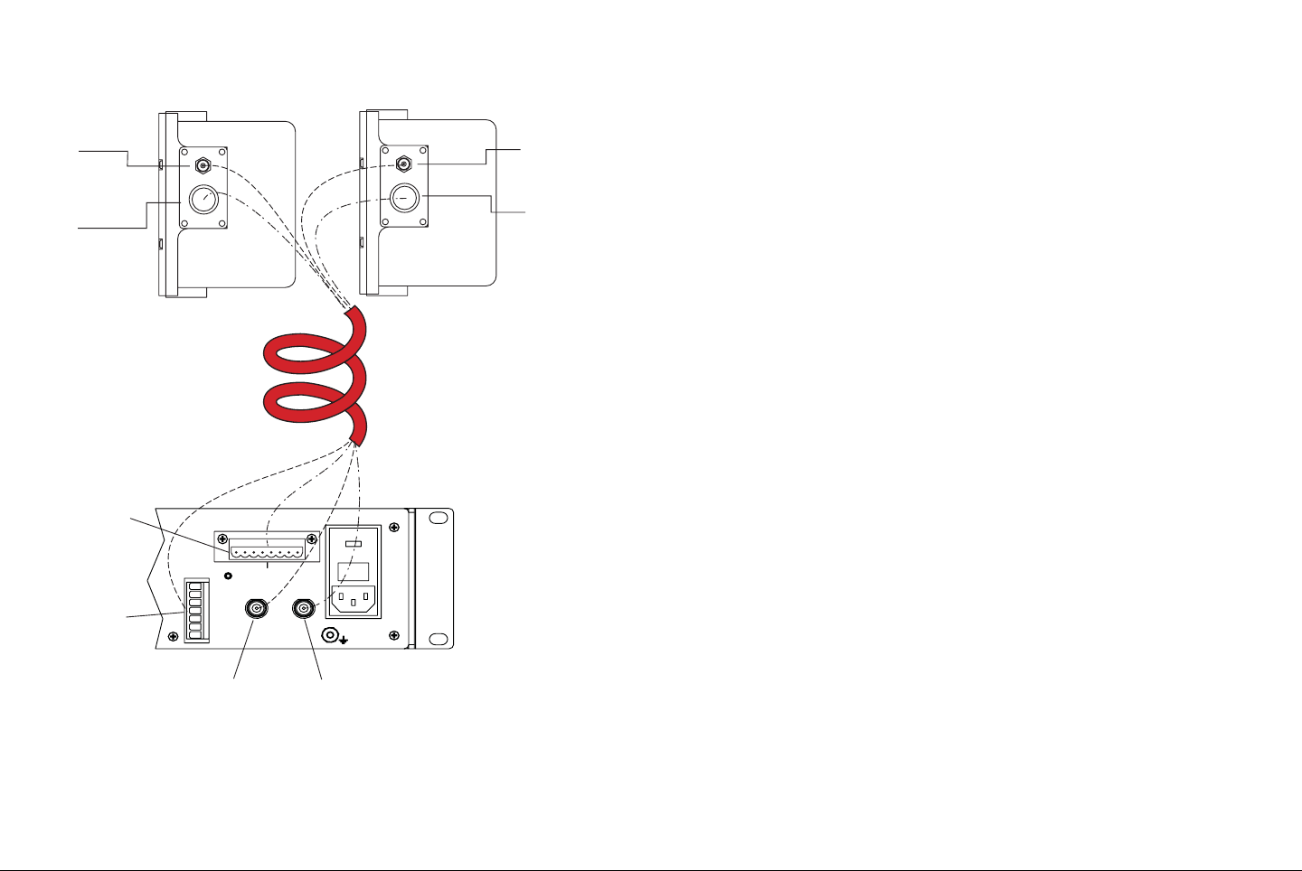
Installation 6-7MTX5000 User and Technical Manual
Figure 6-4: Type “N” and TNC Cabling - Typical
RFU POWER
OUT
ANTENNA
CONTROL
RF UNIT 2
"N" OR TNC
CONNECTOR
RF UNIT 2
"N" OR TNC
CONNECTOR
RF UNIT 1
"N" OR TNC
CONNECTOR
RF UNIT 1
"N" OR TNC
CONNECTOR
POWER
CONNECTOR
POWER
CONNECTOR
ANT
CONTROL
RFU POWER OUT
RFU 1 RFU 2
H
V
LCP
ANT2
BAND2
GND
+
- - + +
- - + +
12
POWER IN
NOTE:
Connections from the ODU to the
antenna are always Type “N”.
6.8.3 Select the Function Cables Required
In addition to the RF signal and DC power, the wiring harness
may include several other cables which are used to control
functions at the top of the mast. What cables need to be
included in the wiring harness are application dependent.
You may choose to procure your own cables and Nycoil conduit
and fabricate your own harness, or an ENG van integrator may
procure or fabricate the harness for you.
Selecting Function Cables Table 6-1 on page 6-8 provides the
most commonly requested functions. To select the cables for
your wiring harness, perform the following:
1. Select the functions you require.
2. Read across the table to see what individual cables
are applicable to your particular requirements. These
are the cables that should be included in the harness.

Installation 6-8MTX5000 User and Technical Manual
Table 6-1: Functions and Cables Required
Function Cable Description
(Vendor Part Number) Outside Diameter
Inches [mm]
IF + DC Power to ODU
IF signal + DC Power + ODU Control TRIAX
(Belden 8232) .315
[8.0 mm]
Antenna Functions
Antenna Polarization Control - Single Band Operation 6 Conductor 20 AWG stranded
(Manhattan M33406) .255
[6.47 mm]
Antenna Polarization Control - Dual Band Operation 10 Conductor 20 AWG stranded
(Manhattan M33410) .335
[8.5 mm]
Existing Wiring
IF Signal + ODU Control Coaxial, Type N Connectors
(RG-214) .425
[10.79 mm]
2A20 POL CTL/PA200/PA700 5 Conductor 20 AWG Stranded
(Belden 9445) .239
[6.07 mm]
Standard ODU
Type N and TNC Connectors 9 Conductor 20 AWG Stranded
(Belden 9455) .317
[8.05 mm]
High Power ODU
Type N Connector 7 Conductor 16 AWG Stranded
(Belden 8621)
(Recommended for both Standard and
High Power ODU installations)
.458
[11.63 mm]
Nycoil Conduit
Nycoil Conduit
(Nycoil 19081) 1”
[25.4 mm]
Nycoil Conduit
(Nycoil 20001) 1.25”
[37.5 mm]
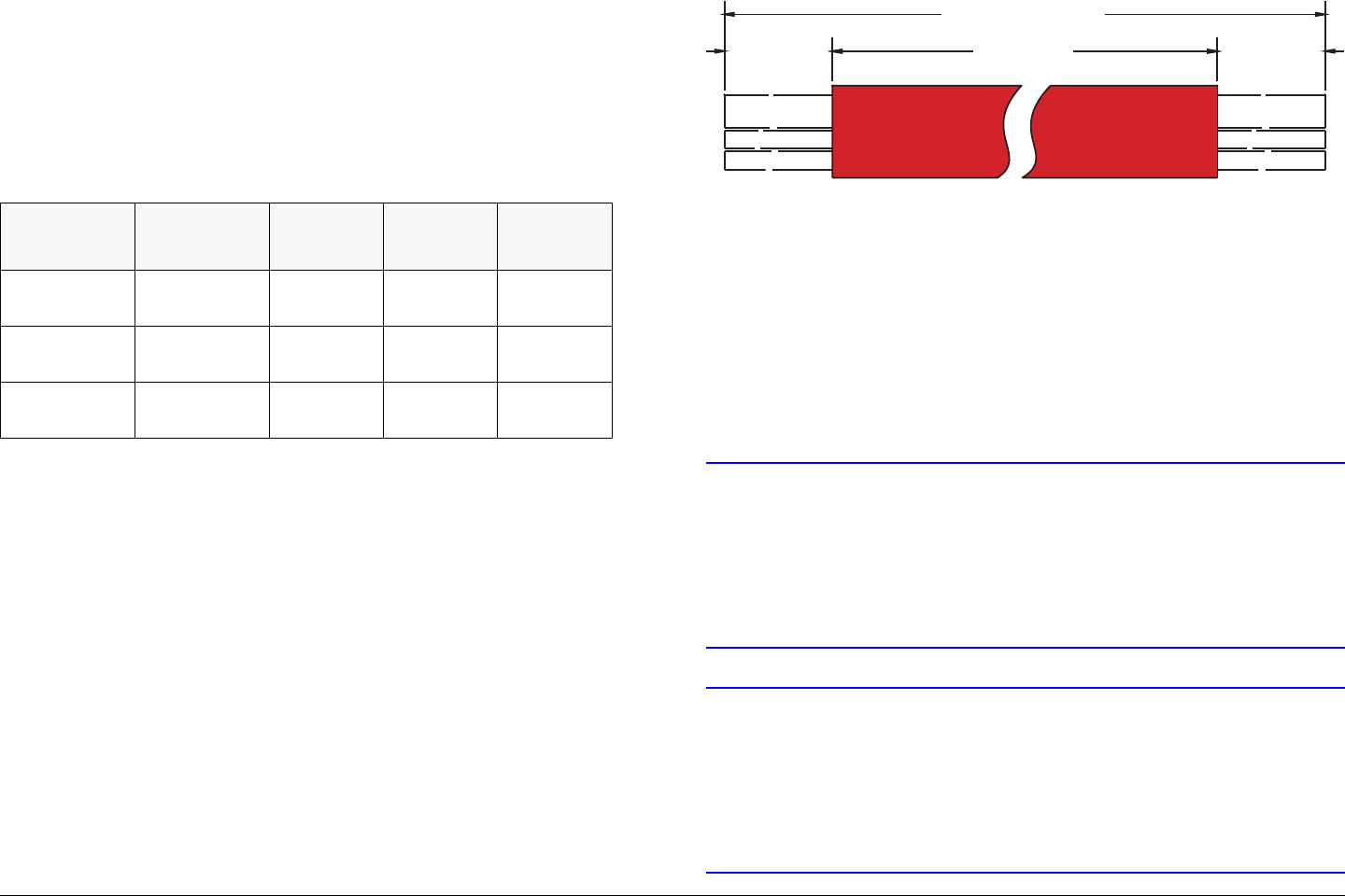
Installation 6-9MTX5000 User and Technical Manual
6.8.4 Determine the Size of Harness Required
Length The length of your harness is set by the length of the
mast when fully raised. Refer to Table 6-2 to locate typical
dimensions, as shown in Figure 6-5. Note these are only typical
dimensions. Your harness may be different.
The formula used to determine theoretical end-to-end cable
lengths (See Figure 6-5) is as follows:
Overall Length = (DIM A - 5 ft.) x 2 + DIM B + DIM C
For example, with a mast height of 58 ft., minus 5 ft. inside the
truck = 53 ft. x 2 = 106 ft. + 10 ft. + 20 ft. = 136 ft.
Table 6-2: Harness Dimensions
Mast
Height Overall
Length Dim. A Dim. B Dim. C
42’
[12.8 M] 104‘
[31.7 M] 74’
[22.5 M] 20‘
[6.0 M] 10‘
[3.0 M]
48’
[14.6 M] 116’
[35.4 M] 86’
[26.2 M] 20‘
[6.0 M] 10‘
[3.0 M]
58’
[17.7 M] 136’
[41.5 M] 106‘
[32.3 M] 20‘
[6.0 M] 10‘
[3.0 M]
Figure 6-5: Harness lengths
6.9 Cabling Requirements
CAUTION To avoid potential problems, existing wiring
harnesses must be carefully examined for
evidence of damage, corrosion, or broken
wire strands, and any damage detected
must be repaired before a new MTX5000
system is placed into service.
CAUTION Failure to provide sufficient current carrying
capacity between the MTX5000 IDU and the
ODU(s) may cause performance issues,
including dropouts in transmission, and may
cause damage to the equipment or to the
installation.
DIM A
DIM A
Overall Length
Overall Length
DIM C
DIM C
DIM B
DIM B
Nycoil Conduit
Nycoil Conduit
IDU End
IDU End
ODU En
dODU End
A = Length of Nycoil only
B = Length of cables outside Nycoil on IDU end
C = Length of cables outside Nycoil on RFU (RFU) end

Installation 6-10MTX5000 User and Technical Manual
MRC strongly recommends using a 4-conductor, 16 AWG
wire combination for DC power that supports Standard and
High Power ODUs.
Specifically, wiring should be in accordance with Table 6-3 for
Standard ODU use and Table 6-4 on page 6-11 for High Power
ODU use.
MRC recommends that installations of the MTX5000 IDU and
ODU be carefully considered, especially where the DC power to
the ODU is concerned. All ODUs used to support digital
(COFDM) transmission require higher linearity and therefore
require more input current to the power amplifiers to achieve
acceptable levels of Modulation Error Ratio (MER) performance.
This is especially true of the optional High Power ODUs.
For new Nycoil installations where the cable length is 160 feet
(48.8 M) or less, MRC suggests two 16 AWG multi-strand
conductors in parallel for both power and return. In a new
installation, this is less likely an issue, however for an existing
installation, other alternatives may be more appropriate.
The following factory recommendation applies to existing
installations. At the very least, all cabling in an existing
installation must be inspected to ensure that no corrosion or
broken strands are present, especially if new conductors are not
used.
The acceptable cable lengths for existing Standard power ODU
installations, or alternatives to the recommendation, are provided
in Table 6-3 as a function of mast height. The recommended
lengths are end-to-end cable length vs. mast height.
The acceptable cable lengths for high power ODU installations,
or alternatives to the recommendation, are provided in Table 6-4
on page 6-11 as a function of mast height. The recommended
lengths are end-to-end cable length vs. mast height.
Table 6-3: Existing Installation Cable Lengths - Standard
Power ODU
Mast Height RF
Connector
Type
Minimum
Wiring for
Power and
Return
Assumed
Maximum
Cable
Length
< 58 Feet Triax Triax 160 ft.
(48.8.0 M)
< 58 Feet N4 Conductors
of 16 AWG (2
Power, 2
Return)
160 ft.
(48.8 M)
< 58 Feet N4 Conductors
of 20 AWG (2
Power, 2
Return)
140 ft.
(42.7 M)
< 58 Feet N7 Conductors
of 20 AWG (4
Power, 3
Return)
160 ft.
(48.8 M)
< 58 Feet TNC 8 Conductors
of 20 AWG (4
Power, 4
Return)
160 ft.
(48.8 M)

Installation 6-11MTX5000 User and Technical Manual
Contact MRC for assistance to determine the effective maximum
cable length for any desired configuration, as required.
6.9.1 MTX5000 System Type “N” Connector
Interface
Table 6-4: Existing Installation Cable Lengths - High Power
ODU
Mast Height RF
Connector
Type
Minimum
Wiring for
Power and
Return
Assumed
Maximum
Cable
Length
< 42 Feet Triax Triax 104 ft.
(31.7 M)
< 58 Feet N4 Conductors
of 16 AWG (2
Power, 2
Return)
160 ft.
(48.8 M)
< 20 Feet N, TNC 4 Conductors
of 20 AWG (2
Power, 2
Return)
60 ft.
(18.3 M)
< 52 Feet N7 Conductors
of 20 AWG (4
Power, 3
Return)
124 ft.
(37.8 M)
< 52 Feet TNC 8 Conductors
of 20 AWG (4
Power, 4
Return)
124 ft.
(37.8 M)
CAUTION To avoid potential problems, existing wiring
harnesses must be carefully examined for
evidence of damage, corrosion, or broken
wire strands.
Any damage detected must be repaired
before a new MTX5000 system is placed
into service.
Note The MTX5000 IDU is available with either the RFU
1 or with both RFU 1 and RFU 2 rear connectors.
If you have only one ODU, disregard connections
and references to the second ODU (RFU 2).
If your MTX5000 IDU and ODU contains the Type “N” connector
RFU 1 and RFU 2 option, the IDU and ODU can be connected
using an existing wiring harness after inspection, subject to the
limits called out in “Cabling Requirements” on page 6-9.
ODU Connections The existing connector(s) at the ODU end of
the wiring harness will connect directly to your MTX5000
ODU(s). Verify that all connections have been completed, as
shown in Figure 6-6 on page 6-12.
IDU Connections At the IDU end of the wiring harness, verify
the connections are as shown in Figure 6-6 on page 6-12.
Connections for ODU 2 (RFU 2) are identical to those for ODU 1
(RFU 1).
The ITT Cannon KPT06F14-12SX connector is utilized on
MTX5000 IDU/ODU configurations that contain the Type “N”
RFU 1 and RFU 2 connector option.
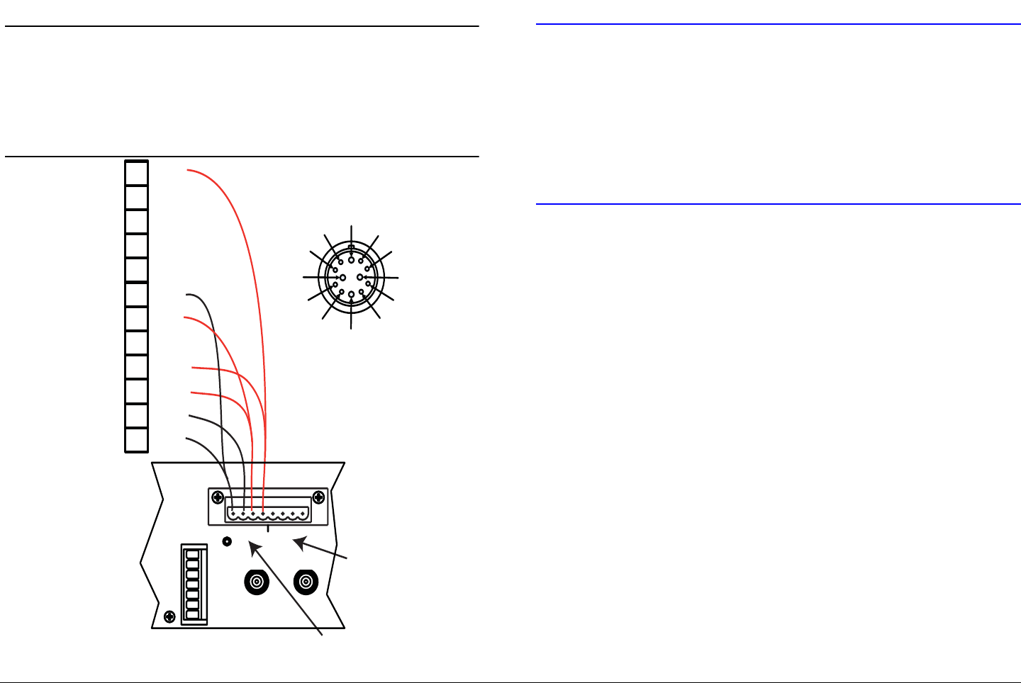
Installation 6-12MTX5000 User and Technical Manual
Figure 6-6: ODU Wiring
M
F
E
A
BC
D
G
H
J
K
L
A
B
C
D
E
F
G
H
J
K
L
M
+12V
+12V
GND
GND
BRN
N/C
N/C
N/C
BLU
YEL
RED
VIO
GRN
BLK
ITT CANNON KPT06F14-12SX
Harness Connections
for ODU 2 (RFU 2)
Harness Connections
for ODU 1 (RFU 1)
+12V
+12V
GND
N/C
N/C
ANT
CONTROL
RFU POWER OUT
RFU 1 RFU 2
H
V
LCP
ANT2
BAND2
GND
+
- - + +
- - + +
12
Note If only two conductors each for power and return
are used, contacts J, K, L, and M must be used.
Contacts J, K, L, and M will accommodate up to
16 AWG single conductor wiring; all other
contacts will accommodate 20 AWG single
conductor wiring.
6.9.2 MTX5000 System TNC Connector Interface
CAUTION To avoid potential problems, existing wiring
harnesses must be carefully examined for
evidence of damage, corrosion, or broken
wire strands.
Any damage detected must be repaired
before a new MTX5000 system is placed
into service.
If your MTX5000 IDU and ODU contain the TNC RFU 1 and
RFU 2 connectors, the IDU and ODU can be connected using an
existing harness,
ODU End The existing power connector at the ODU end will
plug in directly to your ODU.
IDU End At the IDU end, the harness connector will not plug
directly into your IDU. You must cut off the terminal block at the
IDU end and must connect the wiring harness to the Weidmuller
connector supplied with the IDU. Verify the new connections are
as shown in Figure 6-7 on page 6-13. Connections for ODU 2
(RFU 2) are identical to ODU 1 (RFU 1).
The actual number of wires in your harness, and their gauges,
may differ from the standard harness. To provide enough current
to the RFU, MRC recommends the minimum power and ground
connections specified in “Cabling Requirements” on page 6-9
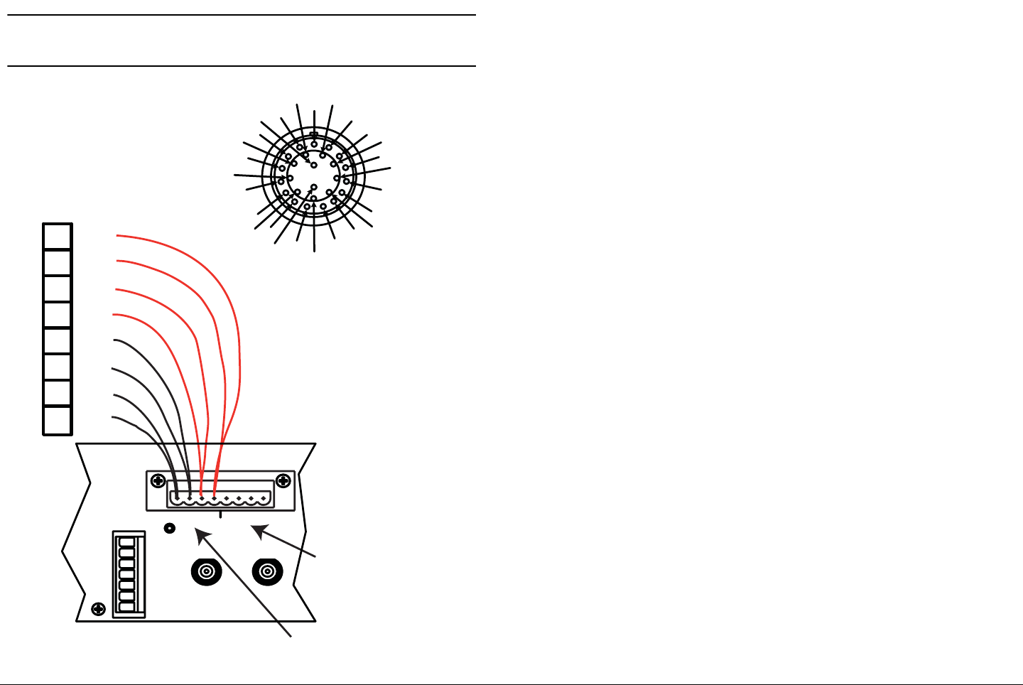
Installation 6-13MTX5000 User and Technical Manual
Figure 6-7: TNC Connector Option Wiring
A
B
C
D
E
F
G
H
J
K
L
M
N
P
R
ST
U
V
W
X
Y
Z
a
b
c
P
R
S
T
U
V
W
X+12V
+12V
GND
GND
ITT CANNON KPT06F16-26S
+12V
+12V
GND
GND
Harness Connections
for ODU 2 (RFU 2)
Harness Connections
for ODU 1 (RFU 1)
ANT
CONTROL
RFU POWER OUT
RFU 1 RFU 2
H
V
LCP
ANT2
BAND2
GND
+
- - + +
- - + +
12
Note All contacts will accommodate 20 AWG single
conductor wiring only.
6.10 Installing the Fabricated Harness
Wiring mounted in a moving vehicle is subject to extremes of
temperature, humidity, and vibration. MRC recommends the
following good general practices:
• Secure the cabling at close intervals along its entire
length.
• Protect the cabling with additional sheathing or padding
anywhere it passes through a hole or lays against an
obstruction.
• Provide flex relief at any location where the cable must
change direction sharply, to maintain a smooth bend and
prevent kinking.
• Provide strain relief at each connector to absorb any
pulling forces on the cable and prevent damage to the
connector.
6.11 Installing the Outdoor Unit
This section provides the steps required to mount the ODU to a
QuikSet QPT-90 Pan & Tilt Assembly, using the Mounting Plate
that was provided with your MRC antenna. The mounting
hardware is provided with the RFU.
The Mounting Plate is designed to fit the following antennas:
• MRC 2A20/7A30
• MRC 2A20SS/7A30SS
• MRC Ellipse 2000
Details on attaching these antennas to the Mounting Plate can
be found in the installation manual that came with your MRC
antenna.
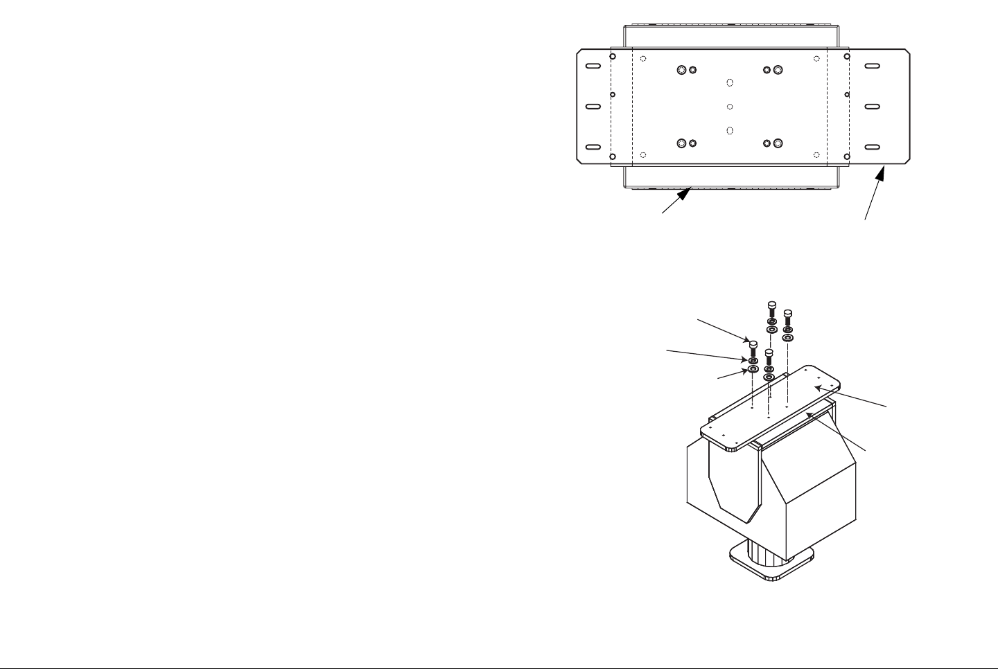
Installation 6-14MTX5000 User and Technical Manual
If you are installing the RFU in a different configuration, consult
the installation instructions that came with your hardware.
When you have installed the RFU, go to “Making the
Connections” on page 6-15.
6.11.1 Site Preparation
Each installation will be different. In general, MRC recommends
the following sequence:
• Install the mast.
• Lower the fabricated wiring harness over the mast.
• Mount the Pan & Tilt to the mast.
• Mount the RFU(s) to the Pan & Tilt. See ”Mounting the
ODU” .
• Mount the antenna to the Pan & Tilt.
6.11.2 Mounting the ODU
The following instructions describe mounting one ODU (RFU).
To mount a second ODU, repeat the steps.
1. Attach the Mounting Plate to the Pan & Tilt Assembly.
- Align the Mounting Plate to the Pan & Tilt mount as
shown in Figure 6-8.
- Attach the Mounting Plate to the Pan & Tilt mount
using #10-32 screws, lock washers, and flat washers
supplied. See Figure 6-9.
2. Attach the ODU to the Mounting Plate.
Figure 6-8: Alignment of Mounting Plate to Pan and Tilt
Figure 6-9: Mounting Plate Attachment to Pan and Tilt
Pan and Tilt Assembly Mounting Plate
MOUNTING
PLATE
PAN & TILT
MOUNT
#10 SCREW
#10 LOCKWASHER
#10 FLAT WASHER
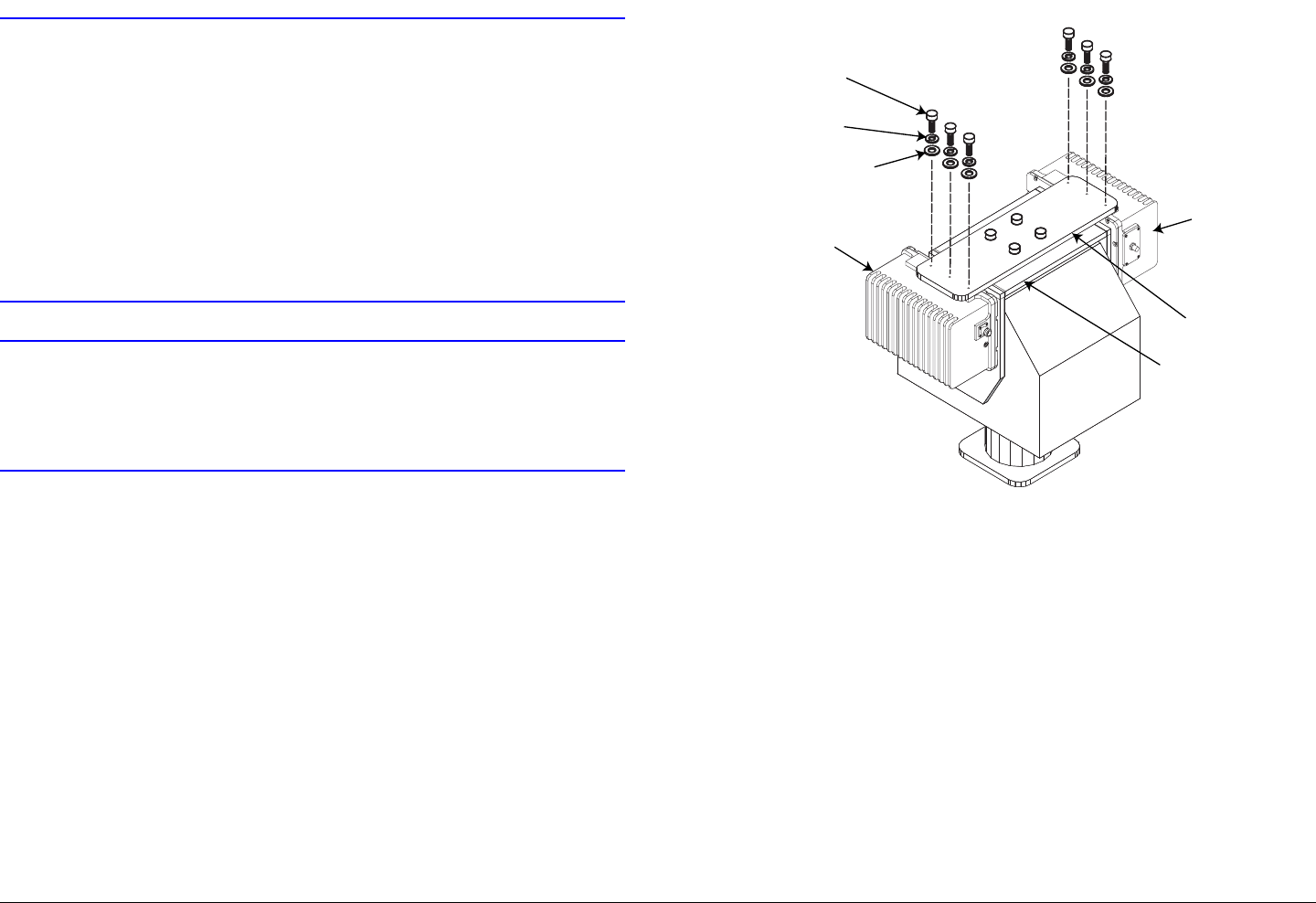
Installation 6-15MTX5000 User and Technical Manual
CAUTION Screws must not penetrate into the holes on
the ODU housing more than .25 in. (6.35
mm).
DO NOT substitute longer screws unless
your installation requires the additional
length.
Over-length screws can crack the housing
when tightened.
CAUTION To ensure proper cooling of the ODU, the
unit must always be mounted so that the
cooling fins are vertical and are not blocked
from free air flow.
3. Align the holes in the ODU with the 3 elongated holes
at one end of the Mounting Plate.
4. Attach the ODU to the mounting plate using the
#10-32 screws, lock washers, and flat washers
supplied. See Figure 6-10.
Figure 6-10: Attaching ODU(s) to Mounting Plate
6.12 Making the Connections
Now that the IDU and ODU(s) are in place and the harness is
installed, make the connections at each end of the harness.
While every installation is different, here are some general
guidelines:
• When you’re done making all connections, re-check all
connections before powering up the MTX5000.
• If you need to install the Triax connector(s) onto the cable,
refer to Appendix A, “Installing Triax Connectors” on
page A-1.
#10 LOCKWASHER
#10 FLAT WASHER
#10 SCREW
MOUNTING
PLATE
PAN & TILT
MOUNT
OUTDOOR UNIT
OUTDOOR UNIT

Installation 6-16MTX5000 User and Technical Manual
6.12.1 Mast Top Connections
For connections at the top of the mast, refer to Figure 6-11 on
page 6-17 which shows a typical installation with a parabolic
antenna and an RF switch. Refer to Figure 6-12 on page 6-18
which shows a typical installation with a Parabolic antenna
without an RF switch. Additional resources are as follows:
• For details on connections at the ODU, refer to Figure 6-
11 on page 6-17 and Figure 6-12 on page 6-18.
• For details on connections to the antenna(s) refer to the
Installation Guide that came with the antenna.
• If you are using an MRC RF Switch, refer to the
Installation Guide that came with the Switch.
6.12.2 IDU Connections
Refer to Figure 6-13 on page 6-19 and Table 6-5 on page 6-20
for connections to the IDU.
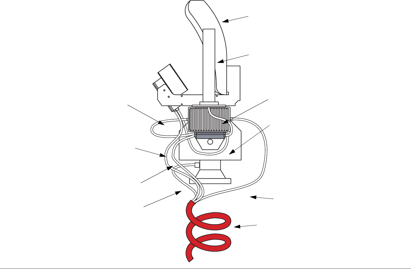
Installation 6-17MTX5000 User and Technical Manual
Figure 6-11: Typical Installation with RF Switch and Triax
Parabolic
Antenna
Omnidirectional
Antenna
Nycoil
Conduit
IF Feed
from IDU to
ODU
Output of
ODU to
Input of
RF Switch
Output of RF
Switch to
Parabolic
Output of RF
Switch to
Omni
Power and
Polarization
Control to
Parabolic
Pan & Tilt
Control
Power and
Control to
RF Switch
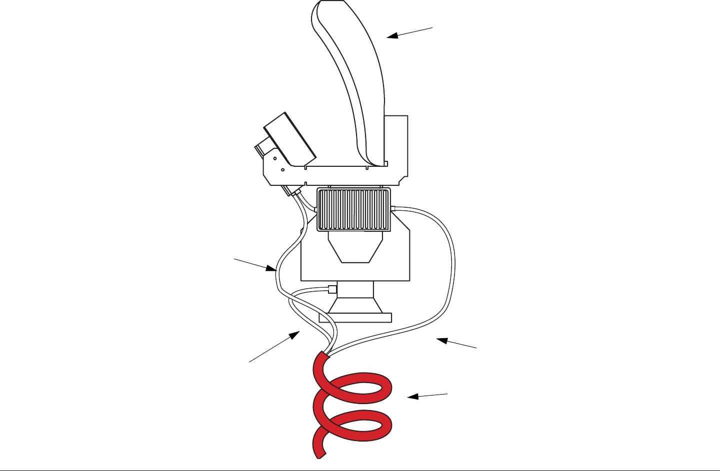
Installation 6-18MTX5000 User and Technical Manual
Figure 6-12: Typical Installation with Parabolic and Triax
Parabolic
Antenna
Nycoil
Conduit
IF Feed
from IDU to
ODU
Power and
Polarization
Control to
Parabolic
Pan & Tilt
Control
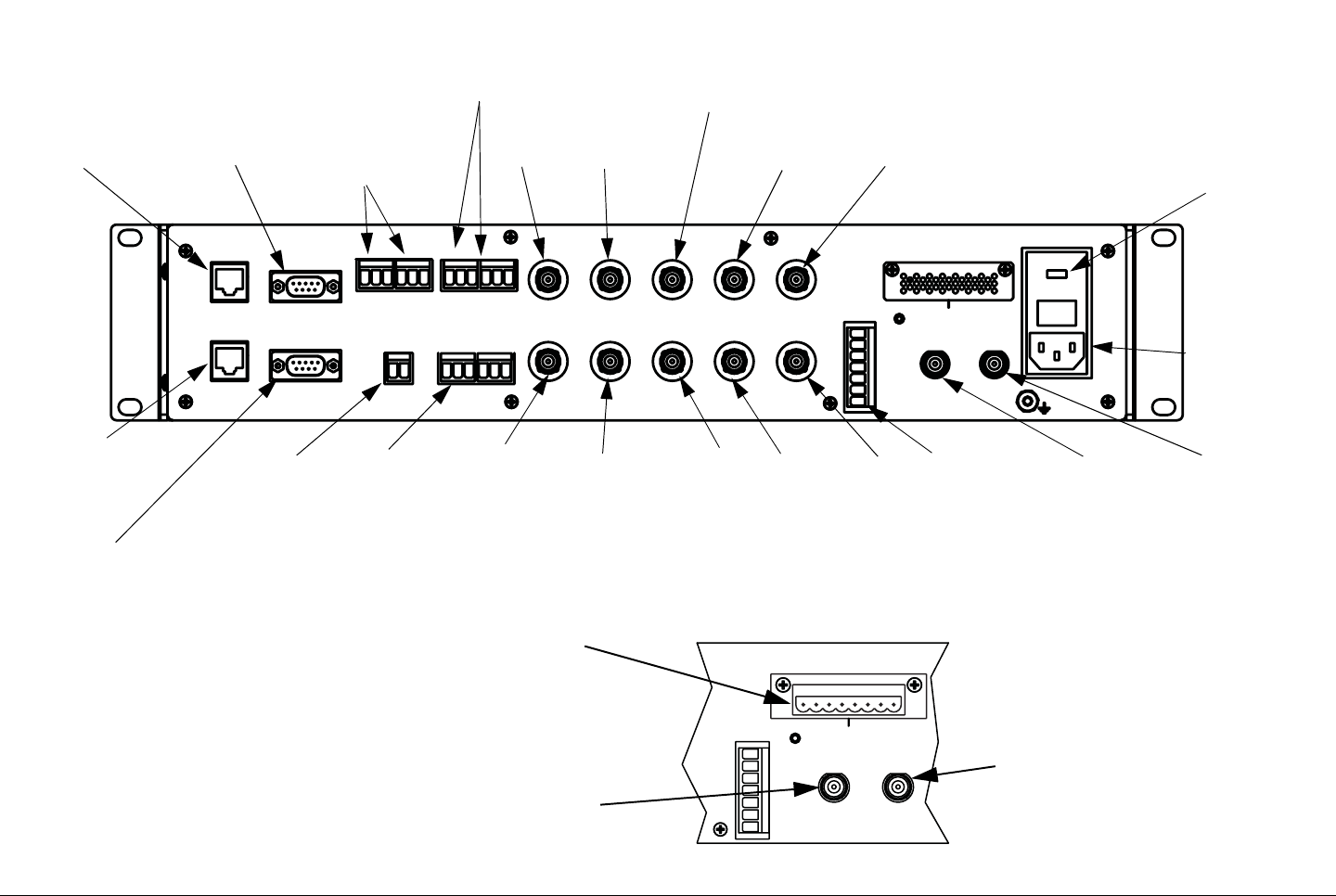
Installation 6-19MTX5000 User and Technical Manual
Figure 6-13: IDU Rear Panel Connections
ETHERNET
RTN DATA
WAYSIDE
ATPC
AUDIO
1234
+ G - + G - + G - + G -
SUM
ALARM
AES/EBU VIDEO IN
BB IN IF MON
AC-3
SMPTE 302
ASI 1 HD-SDI ASI 2
IF IN VID MON SDI/ASI
ANT
CONTROL
RFU POWER OUT
RFU 1 RFU 2
H
V
LCP
ANT2
BAND2
GND
+
- - + +
- - + +
12
POWER IN
+ G - + G -
12
ETHERNET WAYSIDE AUDIO
1 and 2
RTN DATA
(Not Currently
Active)
BB IN IF MON
ASI 1 (Not
Currently Active)
HD-SDI ASI 2 (Not
Currently Active)
RFU POWER OUT (With Type
“N” or TNC RFU 1 and RFU 2
Connector Options Only)
POWER IN
ATPC (Not
Currently Active)
SUM
ALARM (Not
Currently
Active)
AES/EBU
1 and 2 VIDEO
IN RFU 2 (Tria
x
Option)
RFU 1 (Triax
Option)
ANT
CONTROL
AC-3
SMPTE 302
(Not Currently
Active)
IF IN VID
MON SDI/
ASI
ANT
CONTROL
RFU POWER OUT
RFU 1 RFU 2
H
V
LCP
ANT2
BAND2
GND
+
- - + +
- - + +
12
RFU 1 (Type “N”
or TNC Options)
RFU 2 (Type “N”
or TNC Options)
AC Power
Fuse
(Behind
Cover)
AUDIO 3 and 4
(Not Currently
Active)

Installation 6-20MTX5000 User and Technical Manual
Table 6-5: IDU Rear Panel Connections
Connector Type Function Comments
ETHERNET RJ-45 connector Provides connection via your web
browser to a PC at a remote location
for remote control of the MTX5000
IDU. See ”Remote Control
Operations” on page 6-26
Also provides connection to the
optional Remote Access Subnotebook
PC for mobile operation remote
control. See ”Remote Control
Operations” on page 6-26.
WAYSIDE 9-Pin male D-connector The WAYSIDE connector provides
Wayside data output from the MPEG
module.
See ”Wayside Data Connections”
on page 6-24 for pinouts.
AUDIO 1 thru AUDIO 4 •AUDIO 1 - 3 pin Weidmuller
•AUDIO 2 - 3 pin Weidmuller
•AUDIO 3 - 3 pin Weidmuller
•AUDIO 4 - 3 pin Weidmuller
The AUDIO 1 thru AUDIO 4 male 3-pin
Weidmuller connectors provide analog/
digital switchable stereo audio signal
inputs to the FMT or MPEG modules.
(AUDIO 3 and 4 are currently inactive.)
See ”Analog Audio Inputs” on
page 6-25 for pinouts.
BB IN 75 ohm BNC female connector The BB IN connector provides baseband
input video from an external baseband
source.
Composite analog signal - video +
audio subcarriers
IF MON 75 ohm BNC female connector The IF MON connector provides a 70
MHz IF output for external signal
monitoring purposes.
70 MHz IF output
ASI 1 75 ohm BNC female connector (Currently inactive.) (Currently inactive.)
HD-SDI 75 ohm BNC female connector The HD-SDI connector provides the HD/
SDI data stream input to the IDU. The MTX5000 meets SMPTE 292M
specifications for HD-SDI. The user is
responsible for using cables that meet
SMPTE 292M specifications.
ASI 2 75 ohm BNC female connector (Currently inactive.) (Currently inactive)

Installation 6-21MTX5000 User and Technical Manual
RFU POWER OUT 8-pin Weidmuller male connector The RFU POWER OUT connector
provides DC power to the ODU(s). The RFU POWER OUT connector is
present only if the RFU 1 and RFU 2
connectors are type “N” or TNC
connectors. See ”ODU Power” on
page 6-26 for pinouts.
RTN DATA RJ-45 connector (Currently inactive.) (Currently inactive.)
ATPC 9-pin male D-connector (Currently inactive.) (Currently inactive.)
SUM ALM 2-pin Weidmuller male connector (Currently inactive.) (Currently inactive.)
AES/EBU Two 3-pin male Weidmuller
connectors The two AES/EBU 3-pin Weidmuller
connectors provide external AES/EBU
digital audio inputs to the unit.
See ”Digital Audio Inputs” on
page 6-25 for pinouts.
VIDEO IN 75 ohm BNC female connector Input for analog video. Signal is
connected to both the analog video
modulator module and to the MPEG/
COFDM module.
Input level = 1Vpp
Input impedance = 75 ohms
AC-3 SMPTE 302 75 ohm BNC female connector (Currently inactive.) (Currently inactive.)
IF IN 75 ohm BNC female connector The IF IN connector provides a 70 MHz IF
input to the unit. Input level = 0 to -10dBm
Input impedance = 75 ohms
(70 MHz IF with analog or digital
modulation)
VID MON 75 ohm BNC female connector Analog video output to monitor the analog
color bar generator. Does not contain
program video. Used for setting
characters generated by color bar
generator.
Output is only available if analog color
bar generator is installed.
SDI 75 ohm BNC female connector The SDI connector provides SDI inputs to
the unit. The MTX5000 meets SMPTE 259M
specifications for SDI. The user is
responsible for using cables that meet
SMPTE 259M specifications.
Table 6-5: IDU Rear Panel Connections (Continued)
Connector Type Function Comments
Installation 6-22MTX5000 User and Technical Manual
ANT CONTROL 7-pin Weidmuller connector The ANT CONTROL connector provides
control for antenna polarization, antenna
band selection, the RF switch, and also
provides DC power for the antenna and
the RF switch.
A 7-pin Weidmuller female connector
is provided for new system
applications. For retrofit applications,
the existing 5-pin and 2-pin
Weidmuller female connectors may be
retained. See Table 6-6 on page 6-22
for pinouts.
RFU 1 and RFU 2 •Triax
• N or TNC (optional)
• IF + DC Power + Control to RFU
• IF + Control to RFU (optional)
Connector type depends on which
connector ordered. RFU 2 connector
present only if 2 band option ordered.
POWER IN AC - IEC 3 prong recessed male Supplies power to the MTX5000 system. 110 - 220 VAC, 50/60 Hz
Grounding Lug #8-32 threaded post Connection to chassis ground
Table 6-6: Antenna Control - Feed and Relay Connections
Pin (New
Applications) Pin (Retrofit
Applications) Function Description Comments
Antenna Control
11HSelects horizontal
polarization. Connect pins 1, 2, or 3 to GND (pin 6 or 1 in Feed/Relay
Power below) to select desired polarization. If all are left
ungrounded, antenna defaults to right circular (RC)
polarization. Selecting Ant. Pol. option button options on color
LCD display panel causes each pin, in turn, to be grounded or
all to be ungrounded. When ungrounded, should have +24
volts DC returning from antenna.
22VSelects vertical
polarization.
33LCP Selects left circular
polarization.
Table 6-5: IDU Rear Panel Connections (Continued)
Connector Type Function Comments

Installation 6-23MTX5000 User and Technical Manual
44ANT 2 Selects second
antenna using RF
switch.
Connect GND from RF switch here. Selecting Antenna option
button options on color LCD display panel to select Direct
grounds this pin and causes RF switch to select the directional
antenna. Selecting the Omni option ungrounds this pin and
switches back to the omnidirectional antenna.
When ungrounded, should have +24 volts DC returning from
RF switch.
55BAND 2 Selects second
band on dual band
systems.
Selecting RF Band option button options on color LCD display
panel grounds this pin and causes band switch inside ODU to
operate. Selecting the alternate band from the RF Band option
button options ungrounds this pin and switches back to Band 1.
When ungrounded, should have +24 volts DC returning from
antenna.
Feed/Relay Power
61GND Ground
72+Supplies +24 VDC
to antenna and RF
switch.
Table 6-6: Antenna Control - Feed and Relay Connections (Continued)
Pin (New
Applications) Pin (Retrofit
Applications) Function Description Comments

Installation 6-24MTX5000 User and Technical Manual
6.13 Wayside Data Connections
6.13.1 Wayside Connections
The Wayside channel is a simplex data channel transmitting data
from the MTX5000 system to a receiver system. For pinouts,
see Table 6-7.
6.13.2 Compatibility
MRC has verified that the Wayside channel is compatible with
the following receivers:
• STRATA Receiver Unit (RXU) with MPEG decoding
• STRATA Receiver Control Unit (RCU) with MPEG
decoding.
• Tandberg Alteia IRD (Integrated Receiver Decoder)
Table 6-7: WAYSIDE Data Connections
Connector
Information Pin Signal
Description
9-Pin, Male, “D”
Connector. 1UART_TX
2UART_RX
3Return
4NC
5NC
6NC
7NC
8NC
9NC
6.14 Audio Connections
6.14.1 Audio Inputs
The MTX5000 IDU provides inputs for both analog or digital
audio, depending on how the MTX5000 is configured. The IDU
configurations all use 3-pin Weidmuller connectors. The analog
AUDIO 1 thru AUDIO 4 and digital AES/EBU connectors are
mounted on the rear panel of the IDU. (The AUDIO 3 and 4 and
AES/EBU connectors are currently inactive.)
The MTX5000 provides options for separate audio and video
outputs, as well as analog composite and embedded digital
formats. Analog audio inputs are factory-configured for each
customer’s requirements.
• Each MTX5000 is shipped with pre-installed factory
Presets, as specified and ordered by the customer.
• Hardware - Internal cabling connections from the
MTX5000 AUDIO connectors to the FMR and/or MPEG/
COFDM modules are factory-configured for each
MTX5000 ordered.
The MTX5000 provides a maximum of four analog audio circuits.
Each audio circuit is a 3-wire balanced circuit capable of carrying
one tone or voice signal. An audio circuit can carry one analog
balanced channel or two digital AES/EBU channels.
• Analog - Four monaural or two stereo channels carried on
two AUDIO connectors (AUDIO 3 and 4 connectors are
currently inactive.)
• Digital AES/EBU - Two digital channels carried on each
AES/EBU connector.
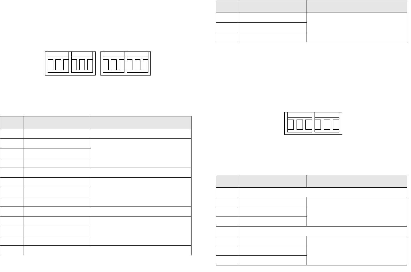
Installation 6-25MTX5000 User and Technical Manual
6.14.2 Analog Audio Inputs
The pinouts of the AUDIO 1 thru 4 analog connectors are shown
in Figure 6-14 and in Table 6-8.
Figure 6-14: AUDIO 1 thru 4 Connectors
Table 6-8: AUDIO 1 thru AUDIO 4 Connections
Pin Function Comments
AUDIO 1
+Audio (+) Input impedance = 600 ohms
GGND
-Audio (-)
AUDIO 2
+Audio (+) Input impedance = 600 ohms
GGND
-Audio (-)
AUDIO 3 (Currently inactive)
+Audio (+) Input impedance = 600 ohms
GGND
-Audio (-)
AUDIO 4 (Currently inactive)
+G- +G- +G-+G-
12 34
AUDIO
6.14.3 Digital Audio Inputs
The pinouts of the AES/EBU channel 1 and 2 digital connectors
are shown in Figure 6-15 and in Table 6-9.
Figure 6-15: AES/EBU 1 and 2 Connectors
+Audio (+) Input impedance = 600 ohms
GGND
-Audio (-)
Table 6-9: AUDIO 1 thru AUDIO 4 Connections
Pin Function Comments
AES/EBU 1
+Audio (+) Input impedance = 600 ohms
GGND
-Audio (-)
AES/EBU 2
+Audio (+) Input impedance = 600 ohms
GGND
-Audio (-)
Table 6-8: AUDIO 1 thru AUDIO 4 Connections (Continued)
Pin Function Comments
+G-+G-
AES/EBU
12
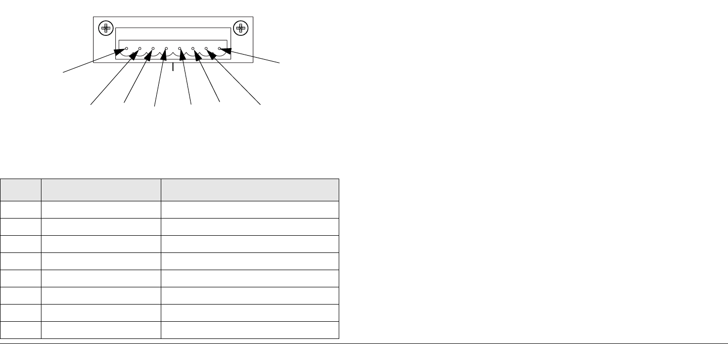
Installation 6-26MTX5000 User and Technical Manual
6.15 ODU Power
DC power is supplied to the ODU(s) from the IDU RFU POWER
OUT 8-pin Weidmuller male connector. This connector is
present only on MTX5000 systems with the optional RFU 1 and
RFU 2 type “N” or TNC connectors.
RFU POWER OUT connector pinouts are shown in Figure 6-16
and Table 6-10. If you only have one ODU (RFU), power must
be provided from the RFU 1 section of the connector.
Figure 6-16: RFU POWER OUT Connector
Table 6-10: RFU POWER OUT Connections
Pin Function Comments
1GND ODU 1 Ground
2GND ODU 1 Ground
3+12 VDC ODU 1 DC Power
4+12 VDC ODU 1 DC Power
5GND ODU 2 Ground
6GND ODU 2 Ground
7+12 VDC ODU 2 DC Power
8+12 VDC ODU 2 DC Power
RFU POWER OUT
- - + +
- - + +
12
1
2
8
7
6
54
3
6.16 Remote Control Operations
The MTX5000 system may be controlled remotely using either
the optional Windows-based Remote Access Subnotebook PC
or a Windows-based laptop PC. The optional Remote Access
Subnotebook PC is a rugged, low cost, remote control option.
Using either laptop eliminates the need for a separate panel-
mounted remote control panel to control the MTX5000 system.
An RJ-45 crossover cable is required for connection to either PC
for mobile remote control operations. See Figure 6-17 on
page 6-27. The RJ-45 crossover cable is connected between
the MTX5000 IDU rear panel ETHERNET connector and the RJ-
45 connector on the optional Remote Access Subnotebook PC
or Windows-based laptop PC.
An RJ-45 crossover cable is provided with each optional Remote
Access Subnotebook PC. If you use a Windows-based PC in
lieu of the optional Remote Access Subnotebook PC, the RJ-45
crossover cable may be obtained from MRC or from local
electronics stores.
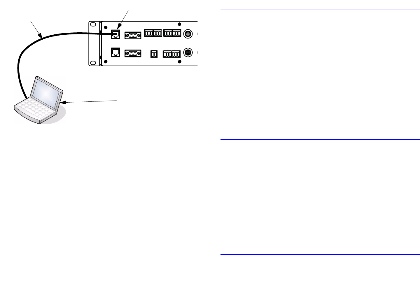
Installation 6-27MTX5000 User and Technical Manual
Figure 6-17: Mobile Operations Remote Control - Typical
The MTX5000 system may also be controlled using a Remote
Access Subnotebook or a Windows-based laptop PC from a
remote location. When controlling the MTX5000 system from a
remote location, the remote PC is connected to the MTX5000
system via the Ethernet. A standard RJ-45 cable is used when
connecting to the MTX5000 system via the Ethernet. A
crossover cable may not be used from a remote location for
connection to the Ethernet.
6.17 Powering Up
When the wiring and installations are completed, it is time to
power up the MTX5000 system. As good practice, you should
make a final check of all wiring and hardware installations before
power is applied.
ETHERNET
RTN DATA
WAYSIDE
ATP C
AUDIO
1234
+ G - + G - + G - + G -
SUM
ALARM
AES/EBU VIDEO IN
BB IN
S
+ G - + G -
12
ETHERNET Connector
RJ-45
Crossover
Cable
Optional Remote Access
Subnotebook PC or
Windows-Based Laptop
6.17.1 Checks Before Power-Up
CAUTION Be sure the power being supplied matches
the power required by the equipment.
Here are your final pre-power-up checks:
• Double check to verify all wiring harnesses and cables are
connected to the correct connectors.
• Make sure all connections are fully mated, properly
mated, and are secured.
• Verify an ODU is properly connected to the IDU.
• Verify all assemblies are properly installed and all
mounting hardware is properly tightened.
6.17.2 Initial Power-Up
CAUTION If power is accidentally lost or if the power
switch is pressed to off, do not immediately
power up the MTX5000 again.
Internal software corruption may occur if
power is applied immediately after a power
loss or if the power switch is pressed to off
and immediately back to on.
To avoid possible software corruption, wait a
minimum of 10 seconds before applying
power or before pressing the power switch
to on.
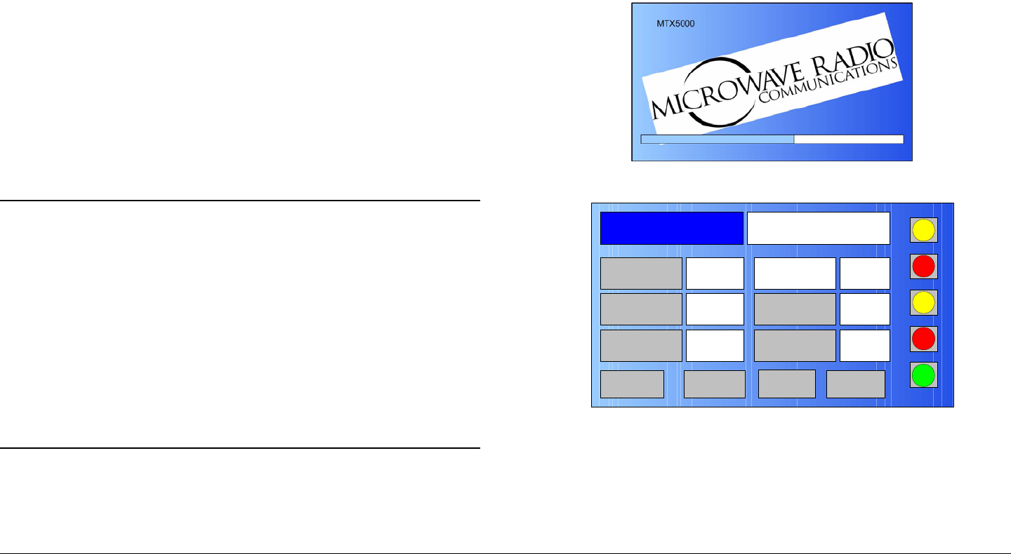
Installation 6-28MTX5000 User and Technical Manual
The procedure required to apply power to the MTX5000 system
is contained in the following steps.
1. Verify the power cable is properly connected to the
MTX5000 IDU rear panel POWER IN AC power
connector.
2. Verify all coaxial cables and cable connectors are
properly connected to the rear panel connectors and
verify the ODU is properly connected.
3. Verify the MTX5000 power cable is connected to AC
power of the correct type and voltage.
4. Verify the AC power source is turned on.
5. Raise the power switch protective switch cover, press
the power switch, observe the symbol on the switch
illuminates green, and close the protective switch
cover.
Note When power is applied to the MTX5000, it will
automatically enter the local normal user mode of
operation.
The MTX5000 will return to the last settings that
were in use when the unit was powered down, but
the MTX5000 will not resume transmitting if the unit
was transmitting when it was powered down.
If the MTX5000 was in the remote mode when
power was removed, the IDU will not return to the
remote mode.
6. The normal power-up sequence is as follows:
- After a short delay (approximately 30 seconds), the
introduction screen will be displayed on the color LCD
display panel. See Figure 6-18.
- After another short delay (approximately 30 seconds),
the Main screen will be displayed on the color LCD
display panel. See Figure 6-19.
Figure 6-18: Introduction Screen
Figure 6-19: Main Screen - Typical
7. If everything appears to be normal, test the
performance of your MTX5000 by setting up a link and
transmitting video and audio.
- If you have any problems, refer to the
“Troubleshooting” Chapter on page 4-1.
Channel 1 0Offset
Antenna Ant. Pol.Antenna1 H
RFU1
No RF
RF Band
Preset A Analog
4.83 & 5.8, 3MHz Vid Dev
RF Output XX
dBm
<- Status Setup Status ->
PA Off
SUM
ODU
IDU
RF
L/R
L
L
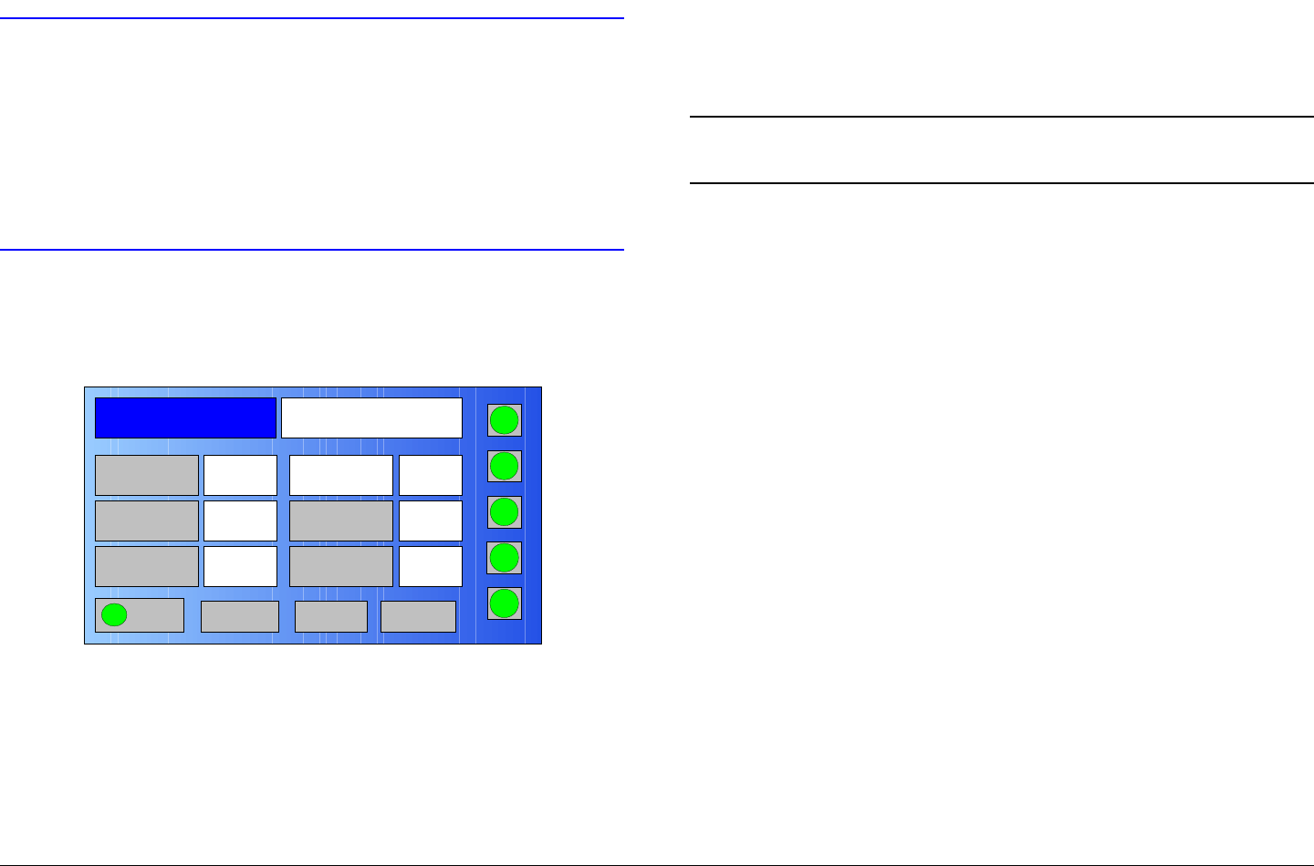
Installation 6-29MTX5000 User and Technical Manual
6.17.3 Power Down
CAUTION To allow proper shutdown of MTX5000
internal software, the Main screen must
always be displayed when the power switch
is pressed to off.
Failure to properly power down the
MTX5000 with the Main screen displayed
may corrupt the internal software.
1. Verify the Main screen is displayed on the color LCD
display panel. See Figure 6-20.
Figure 6-20: Main Screen - Typical
2. Raise the power switch protective switch cover, press
the power switch, observe the symbol on the switch
goes off, and close the protective switch cover.
3. Set the power source off, as required.
Channel 1 0Offset
Antenna Ant. Pol.Antenna1 V
RFU2
7US
RF Band
Preset A Analog
4.83 & 5.8, 3MHz Vid Dev
RF Output XX
dBm
<- Status Setup Status ->
PA On
SUM
ODU
IDU
RF
L/R
H
L
6.18 Product Modifications
The product you purchased has been carefully designed and
tested, and is warranted to meet specifications when connected
and operated as described in this manual.
Note If you modify a product without authorization from
MRC, you will void the warranty.
For a complete Warranty statement, refer to the “Notices“ section
at the front of this manual.

Installation 6-30MTX5000 User and Technical Manual

7
Replacement Parts and
Supported Repairs 7-1MTX5000 User and Technical Manual
Replacement Parts and
Supported Repairs
7.1 Chapter Overview
This chapter identifies replacement parts and supported repairs
applicable to the MTX5000 Transmitter System (MTX5000).
Since there are no supported field repairs on the MTX5000,
the only parts available are external cables and power fuses.
7.2 External Cables and Adapters
The external cables and test cables for the MTX5000 are listed
in Table 7-1. If you need something that is not listed, ask your
Sales Representative or consult the factory.
Table 7-1: MTX5000 System Cables
Description Comments
AC Power Cable (120/240
VAC) Connects AC power to the MTX5000
IDU.
Triax Cable Kit Connects MTX5000 IDU to the ODU.
(IDU Triax RFU 1 and RFU 2
connector option only.)
Color Bar Generator Test
Cable Connects optional Analog Color Bar
Generator
USB-A to USB-B Adapter Connects USB memory stick to
MTX5000 IDU front panel USB-B
connector
7.3 AC Power Fuses
The MTX5000 Indoor Unit (IDU) operates on the following AC
power:
• 120/240 VAC, 50/60 Hz
Fuse ratings for the AC power sources are listed in Table 7-2.
7.4 Supported Repairs
There are NO supported field repairs to the MTX5000 IDU or
the ODU.
Return the unit(s) for factory repair.
If you attempt field repair, you risk damaging your
equipment. If your equipment is under warranty, you may also
affect your warranty coverage.
The MTX5000 is designed to be compact, rugged and reliable.
The MTX5000 Indoor Unit (IDU) and the Outdoor Unit (ODU)
require specialized test equipment and software to calibrate
amplitude and frequency characteristics after repair. In addition,
sealing the ODU enclosure after repair requires exacting
techniques and special fixtures to ensure weather resistance of
the unit.
Table 7-2:
Operating Voltage Fuse Rating
120 VAC, 50/60 Hz 3.0A SB 250V 3AG or 5 x 20 mm
240 VAC, 50/60 Hz 1.5A SB 250V 3AG or 5 x 20 mm

Replacement Parts and
Supported Repairs 7-2MTX5000 User and Technical Manual

8
Theory of Operation 8-1MTX5000 User and Technical Manual
Theory of Operation
8.1 Chapter Overview
This chapter provides additional details about the design and
function of the MTX5000 Transmitter System (MTX5000). This
chapter is intended to complement information contained in the
“Product Description” Chapter on page 2-1.
The descriptions in this chapter assume you are already familiar
with the information contained in Chapter 2. We recommend you
review that chapter before beginning to read this one.
Here are the topics covered:
8.2 System Architecture
8.2.1 General
The MTX5000 is a van-mounted, High Definition (HD) ready,
Topic Page
System Architecture 8-1
General 8-1
Architecture 8-1
MPEG Encoding and COFDM Transmission 8-2
Analog Video Encoding and FM Modulation 8-2
MTX5000 User Interface 8-2
ODU RF Output 8-3
MTX5000 Internal Software 8-3
Outdoor Unit Details 8-5
video transmission system capable of both analog and digital
operation in different formats. The MTX5000 system provides a
sophisticated user interface with an intuitive keypad scheme,
touch screen, and an adjustable color LCD display. The
MTX5000 system consists of the MTX5000 Indoor Unit (IDU)
and the mast-mounted Outdoor Unit(s) (ODU).
A fully equipped MTX5000 package is HD ready and provides a
robust HD link from field to studio. Several digital video input
formats are accepted, as well as analog composite for Digital
Video Broadcasting - Terrestrial (DVB-T) and analog FM
transmission. In addition, the MTX5000 can accept several
digital audio input formats and up to four analog audio inputs for
analog or digital transmission.
The MTX5000 has several mast-mounted ODU configurations
available. These ODUs contain integrated RF up conversion
circuitry and high power RF amplifiers for maximum power and
signal quality. With the demands of digital modulation, the ODUs
have been optimized for improved Modulation Error Ratio/Error
Vector Magnitude (MER/EVM) performance with digital
transmissions.
8.2.2 Architecture
The MTX5000 system consists of the IDU and the ODU(s). The
IDU is responsible for video encoding, modulation, system
control, and power distribution. The ODU contains RF up
conversion circuitry and a power amplifier.
The ODU is mounted at the top of the van mast and is
responsible for all aspects of the RF transmission. Modulated
signals are passed from the IDU to the ODU using a 70MHz IF
signal. In addition, the IDU and ODU communicate through a
bidirectional Frequency-Shift Keying (FSK) modem. This FSK
link allows the IDU to control, calibrate, and monitor the state of
the mast-mounted ODU.

Theory of Operation 8-2MTX5000 User and Technical Manual
A digital attenuator in the ODU RF chain allows you to transmit at
high or low power or to increment the power in single dB steps
for advanced fine tuning.
Inside the IDU, a control processor is responsible for configuring
the various sub-systems within the radio. The main processor
stores radio information in selectable presets that can be
recalled by the user.
The MTX5000 employs an advanced MPEG video encoder and
digital modulator. The MTX5000 includes the FMT modulator,
COFDM modulator and MPEG encoder, DC power supply, and
signal control and distribution boards, depending upon the
options contained in your MTX5000. A typical functional block
diagram of the MTX5000 is shown in Figure 8-1 on page 8-4.
8.2.3 MPEG Encoding and COFDM Transmission
The MTX5000 is capable of encoding both Standard Definition
and High Definition video (depending on license). Available
inputs include SD Serialized Digital Interface video (SD-SDI),
HD-SDI, and Composite Video (CV). Audio input formats include
analog, AES/EBU, and AC-3 SMPTE-302. The encoder is also
capable of encoding an RS-232 signal as Wayside data.
The MTX5000 is capable of generating a fully DVB-T compliant
output signal. This provides a robust digital link in any hostile
transmission environment.
8.2.4 Analog Video Encoding and FM Modulation
When in the analog FM mode, the MTX5000 will accept a
standard composite video input. It will also accept up to four
analog audio inputs. The FM analog signal is useful when
working with older legacy equipment or when an analog
transmission is desired.
8.2.5 MTX5000 User Interface
Local Mode Operation The MTX5000 IDU front panel provides
monitoring and control of the MTX5000 system. The color LCD
display panel with touch screen and the function keys are used
to select control and diagnostic menu screens for both the IDU
and the ODU.
The user interacts with the system through the touch-screen or
function keys. The user interface is broken into a normal user
mode and a system setup or advanced features mode.
Normal user mode menus permit basic radio control without
exposing you to the more complicated setup features available in
the advanced features sections. The advanced features can be
password protected to prevent an unwitting user from changing
critical settings.
Option buttons displayed on the IDU color LCD display panel are
used to control Preset selection, RF band selection, channel
selection, offset selection, antenna selection, antenna
polarization, transmitter operation (on or off), power (low or
high), and to monitor the status of the IDU and ODU. For
additional information, see the “Routine Operation” Chapter on
page 3-1.
The front panel color LCD display panel is also used to select
local or remote control operation of the MTX5000 system.
Remote Mode Operation The MTX5000 system may also be
operated from a remote location via the ETHERNET connector
mounted on the rear panel of the IDU. The IDU can be
connected to a PC at a remote location via your web browser.
The remote mode allows you to control the MTX5000 in the
normal user mode from the remote location using the PC display,
mouse, and keyboard. You cannot perform system setup
advanced features from the remote location.

Theory of Operation 8-3MTX5000 User and Technical Manual
Control of the local/remote mode of operation can only be
controlled from the IDU. You cannot change the local/remote
operating mode from the remote location.
For more information on remote operation, see “Using the
MTX5000 in Remote Mode” on page 3-60.
8.2.6 ODU RF Output
The MTX5000 communicates with the ODU to set operating
frequencies and power levels. A 70 MHz IF signal is up-
converted to the RF band of operation. Before up conversion, a
digital attenuator adjusts the signal output power based on
calibration data and user input.
8.2.7 MTX5000 Internal Software
The MTX5000 internal software package consists of an
embedded controller software package.
For additional information on user interface through use of the
front panel color LCD display screen with touch screen and
function keys, see the “Routine Operation” Chapter on page 3-1.
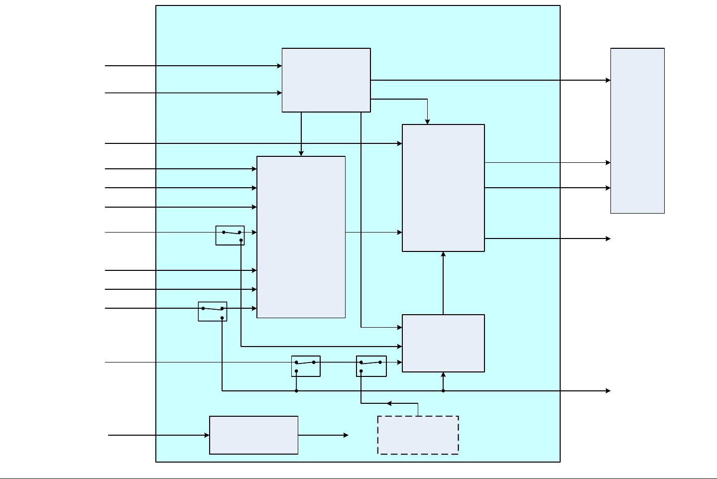
Theory of Operation 8-4MTX5000 User and Technical Manual
Figure 8-1: MTX5000 Functional Block Diagram - Typical
SYSTEM CONTROL
Keypad/LCD Display
User Inputs
IF SWITCH
OUTDOOR
UNIT (ODU)
RFU 1
RFU 2
70 MHz IF
70 MHz IF
ODU Control
70 MHz IF IF MON
ANT
CONTROL
External IF Input
EXT IF
MPEG ENCODER
AND COFDM
MODULATOR
70
MHz
IF
AUDIO
1 - 4
Analog Audio
(4 Channels)
BB IN Baseband Input
VIDEO
IN
Composite
Video
POWER SUPPLY
POWER
IN
110/220 VAC,
50/60 Hz DC Power
Distribution
Composite Video VID MON
SDI/ASI
HD-SDI
AES/EBU
AC-3
SMPTE 302
WAYSIDE Wayside Data
SDI Input
HD SDI Input
Switch Control
MPEG
Control
FMT
70 MHz IF
FMT
Control
ETHERNET
OPTIONAL
ANALOG COLOR
BAR GENERATOR
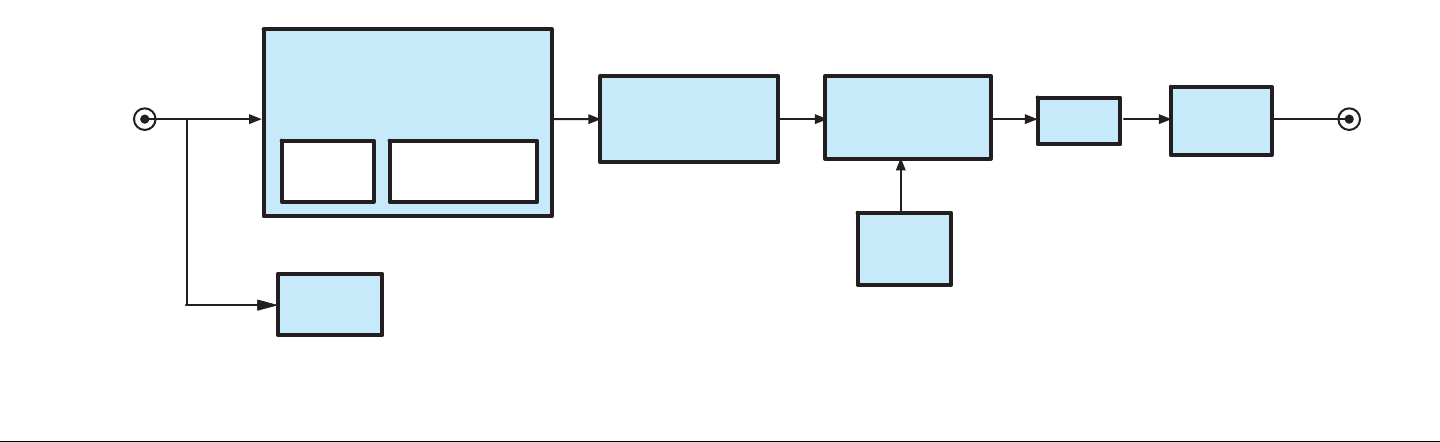
Theory of Operation 8-5MTX5000 User and Technical Manual
8.3 Outdoor Unit Details
The MTX5000 ODU processes the IF signal from the MTX5000
IDU and generates the higher power microwave signal that is fed
to the antenna. The ODU contains the following components:
• An IF interface module, containing a 2 FSK modem. The
modem communicates with the IDU modem to send and
receive alarms and operating data.
• A power supply, which converts the 12 VDC from the IDU
into +15 VDC, -15 VDC, and +5 VDC for use by the other
RFU modules.
• A UHF up-convertor, which converts the 70 MHz IF signal
to 900 MHz.
• A 3 GHz local oscillator, whose frequency is set by a
control voltage from the interface module (a Voltage-
Controlled Oscillator, or VCO).
• A microwave mixer/up-convertor that mixes the 3 GHz
with the the 900 MHz signal, to produce the frequency
desired. For the 7 GHz and 13 GHz bands, this also
includes a frequency doubler or tripler.
• A bandpass filter to eliminate unwanted frequency
components.
• A Power Amplifier (PA) that amplifies the resulting signal
to the power level desired.
A functional block diagram of the ODU is shown in Figure 8-2.
Figure 8-2: ODU Block Diagram
3 GHz
VCO
POWER
SUPPLY
POWER
AMP
UHF
UPCONVERTER
INTERFACE
BOARD
FSK
MODEM MICRO
PROCESSOR
FILTER
MICROWAVE
UPCONVERTER
RF OUTPUT
TO
ANTENNA
70 MHz IF +
DC POWER +
CONTROL

Theory of Operation 8-6MTX5000 User and Technical Manual
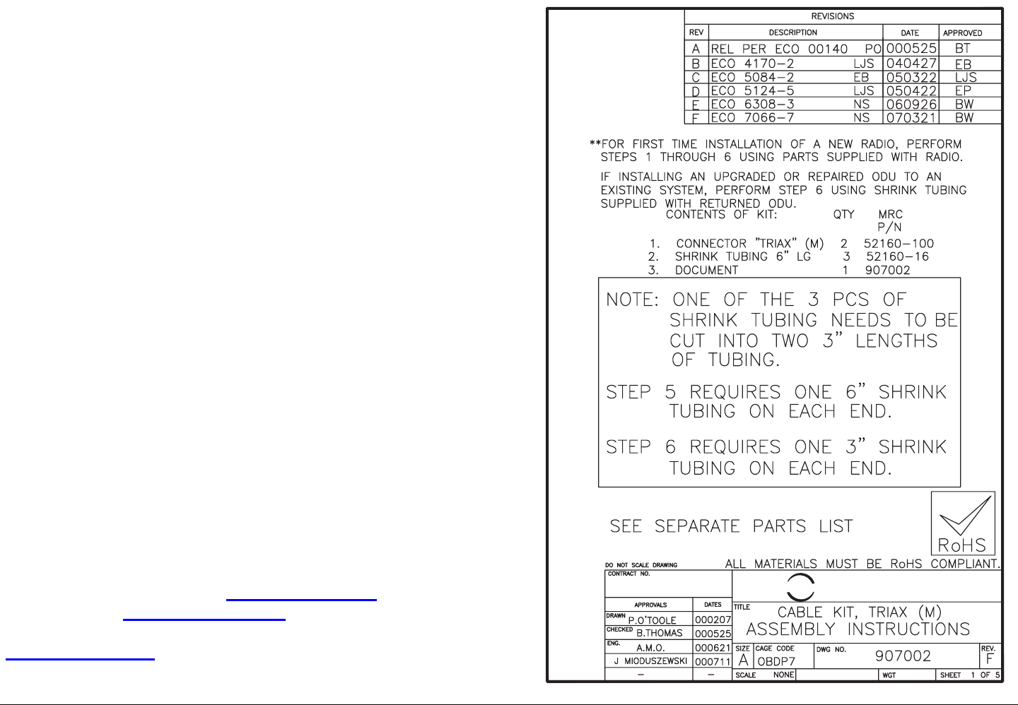
A
Installing Triax Connectors A-1MTX5000 User and Technical Manual
Installing Triax Connectors
A.1 Appendix Overview
Installing Triax connectors on a Triax cable is an exacting job. If
not performed correctly, it can lead to intermittent or permanent
failures due to vibration, moisture, etc.
As a service to our customers, MRC is providing a copy of our
Triax Cable Assembly Instructions. We have found this
procedure to work well and the results to be reliable.
A.2 Sealing
For any outdoor application, such as mast top connections, we
recommend you seal all connections with self-fusing butyl rubber
or silicone tape. Ordinary plastic electrical tape and cloth
friction tape are not recommended.
A good general practice is as follows:
• Connect and tighten the connector
• Begin wrapping the tape tightly against the enclosure, and
wrap in a spiral back toward the cable
• Overlap each turn with the next turn by about half its width
• Continue wrapping and overlapping until the tape extends
at least 2 inches beyond the connector.
Self-fusing tape can be purchased from industrial supply
companies such as Grainger (www.grainger.com) and
McMaster-Carr (www.mcmaster.com). Self-fusing tape is also
available at larger hardware stores such as DoitBest.com
(www.doitbest.com).
COMMUNICATIONS
MICROWAVE RADIO
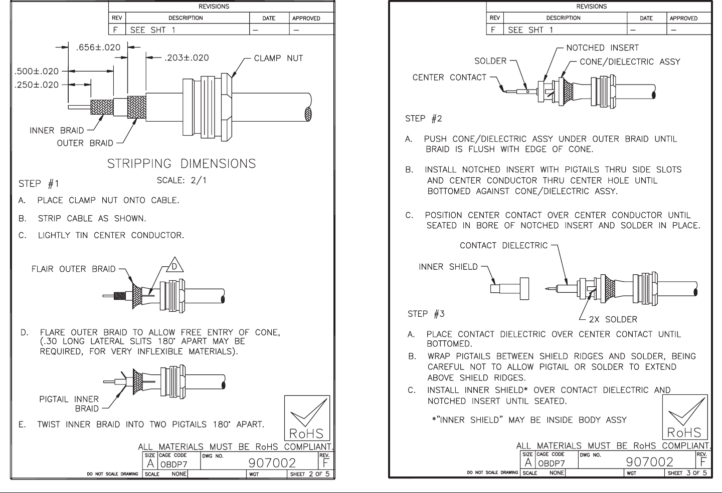
Installing Triax Connectors A-2MTX5000 User and Technical Manual
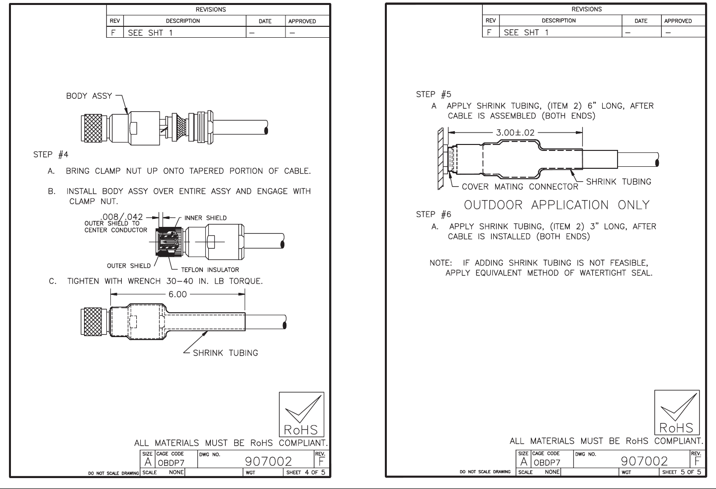
Installing Triax Connectors A-3MTX5000 User and Technical Manual

Installing Triax Connectors A-4MTX5000 User and Technical Manual
This page intentionally left blank.

B
Analog Color Bar Generator B-1MTX5000 User and Technical Manual
Analog Color Bar
Generator
B.1 Appendix Overview
This appendix describes how to set up the optional Analog Color
Bar Generator (CBG). The optional CBG is available in either
NTSC or PAL versions.
The topics covered in this chapter are listed below.
Topic Page
Description B-1
Functions B-1
Operating Modes B-1
Configuration B-2
Technical Background B-2
Configuration B-2
General B-2
Entering Characters B-4
Preliminary Setup Procedure B-4
Configure Text Line A B-8
Configure Text Line B B-9
Configure Control Line B-9
Check the Configuration B-13
Configuration Reference B-16
Button Functions B-16
Full Character Set B-17
Character Subsets B-18
Delay Values B-18
B.2 Description
B.2.1 Functions
The CBG provides the following functions:
• Inserts a color bar pattern conforming to SMPTE
Engineering Guideline EG 1-1990 for SMPTE Color Bars
• Inserts test tones of 440 Hz and 1 kHz
• Lets you create and edit two lines of text that can be
added to the color bar display, at locations you select
• Allows you to control when the color bars and tones are
added to the transmitted signal and when to automatically
place the MTX5000 IDU into the standby mode.
B.2.2 Operating Modes
The CBG has four operating modes that are selected using the
MTX5000 IDU color LCD display panel touch screen and/or
function keys. The four operating modes are displayed on the
color LCD display panel Color Bars screen and are identified as
follows:
•Off - Color bars and audio test tones are turned off.
•On - Color bars and/or audio test tones are continuously
on.
•A Gen (Auto Generated) - If a loss of video signal occurs,
color bars and/or audio test tones are transmitted after a
programmable delay.
•A Stby (Auto Standby) - If a loss of video signal occurs,
the transmitter is automatically placed into standby (PA
turned off).

Analog Color Bar Generator B-2MTX5000 User and Technical Manual
B.2.3 Configuration
Each of the four operating modes can be configured to meet
your needs. Configuration is accomplished using four push
button switches mounted on the CBG board. Configuration is
normally performed only when the MTX5000 IDU is first
installed, or if the CBG has been replaced by the factory.
Configuring the CBG will include specifying the following:
• If the CBG will generate audio tones, video color bars, or
both
• What text will be displayed on screen whenever the color
bars are displayed. There are two lines of text: Text Line
A and Text Line B. Each line contains 16 character fields.
Each character field can display any character in the full
character set.
• Where each text line is displayed on the screen
• Which characters in a text line are visible on the default
screen and which are hidden
• The foreground and background colors of the text lines
• The length of time (delay) the CBG will wait after loss of
video signal before it begins generating tones and/or bars.
Configuration of the CBG consists of selecting the characters for
each of the two lines of text and for a seven-character control
line.
B.2.4 Technical Background
The CBG includes circuits that provide both a video signal, and
audio test tones of 1 kHz and 400 Hz on separate audio
channels (1 kHz on Audio 1, 440 Hz on Audio 2).
Text lines and parameters are stored in memory and are
controlled by a microprocessor. A video detection circuit notifies
the processor whenever a valid external video signal is present.
Non-volatile memory preserves parameters and transmitter ID
information. Once set, no battery or other power is required to
save these parameters.
B.3 Configuration
B.3.1 General
Configuration of the CBG involves using the MTX5000 IDU color
LCD display panel touch screen or function keys, four control
switches on the CBG board (See Figure B-1 on page B-3), and
an external monitor to enter text for the text lines and the
numerical parameters for the control line.
The MTX5000 IDU must be removed from its mounting rack (if
installed). The top cover panel must then be removed to allow
connection between the external monitor and the CBG and to
allow access to the four control switches. Steps are provided in
the following procedures to set all parameters in the CBG.
To avoid potential operator problems that could impact operation
of the MTX5000 System, the IDU color LCD display panel Color
Bars screen Off option must be selected when procedures
contained in this Appendix are completed.
When performance of these procedures is complete, perform
“Select Color Bar Generator Mode” on page 3-52 to select the
CGB operating mode required for Analog Preset operations.
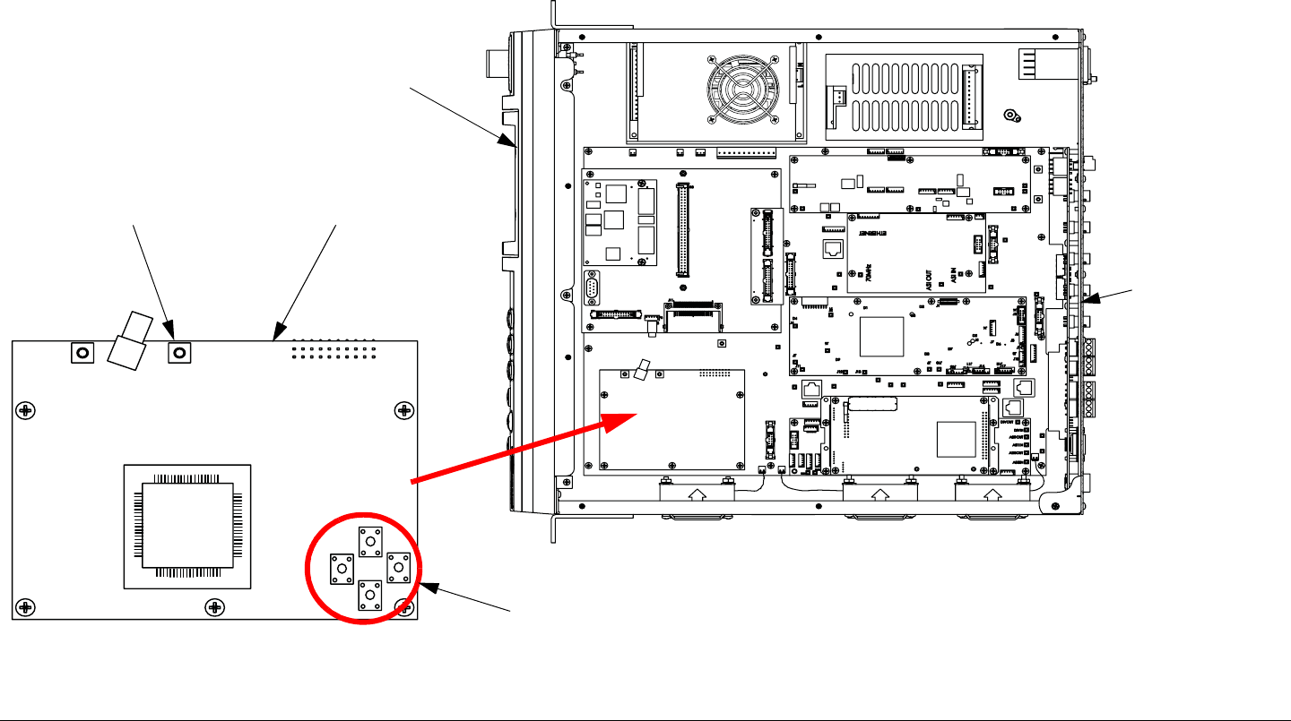
Analog Color Bar Generator B-3MTX5000 User and Technical Manual
Figure B-1: MTX5000 IDU Analog Color Bar Generator
SW1
SW2
SW3
SW4
J2
J3
J4
MTX5000 IDU -
Front Panel
Analog Color
Bar Generator
MTX5000 IDU -
Rear Panel
Control
Switches
Top View - Cover
Panel Removed
Video Monitor
Connector J4
Analog Color Bar Generator B-4MTX5000 User and Technical Manual
B.3.2 Entering Characters
Entering characters utilizes the four CBG control switches in a
similar way to the four arrow keys on a standard computer
keyboard. See Figure B-2. In order to maximize your control
using only four switches, each switch has multiple functions
depending on whether the CBG is in character mode or subset
mode.
Figure B-2: Button Functions
Character Mode In the character mode, scrolling up or down
with switches 1 and 3 will change the highlighted character one
character up or down in the full character set. See Table B-3 on
page B-17.
Subset Mode To make editing the text lines faster, the full
character set is divided into subsets. You can jump from one
subset to the next instead of scrolling through the full character
set one character at a time.
In subset mode, scrolling up or down with switches 1 and 3 will
change the highlighted character one subset up or down within
the list of subsets. See Table B-4 on page B-18.
1
2
3
4
UP
RIGHT
DOWN
LEFT
Hiding Characters If you wish to hide any characters in the
default display, press switches 1 and 3 simultaneously while the
CBG is in subset mode. That character will show in inverse
video and will be hidden from the default display. That character
can still be viewed and changed in the editing mode. A black
background is a hidden character; a white background is a
character that is not hidden.
B.3.3 Preliminary Setup Procedure
The procedure required to set up the optional Analog Color Bar
Generator is contained in the following steps. This procedure
must be performed prior to performing any or all of the following
procedures.
•“Configure Text Line A” on page B-8
•“Configure Text Line B” on page B-9
•“Configure Control Line” on page B-10
•“Check the Configuration” on page B-13
WARNING There are electrical conditions of voltage
and current in this equipment which can
cause death or injury.
Use extreme care when performing this
procedure.
Analog Color Bar Generator B-5MTX5000 User and Technical Manual
WARNING Remove all jewelry before beginning work
on the equipment.
Jewelry can conduct electrical current.
Accidental contact can result in
electrocution or severe burns.
WARNING Rotating equipment (cooling fans) is used in
the operation of this equipment.
When performing this procedure, know the
location of the rotating equipment.
WARNING Remove all jewelry before beginning work
on the equipment.
Jewelry can be caught in rotating equipment
or on protruding parts, resulting in injury.
CAUTION Electrostatic Discharge (ESD)
The MTX5000 IDU and the CBG contain
components that are sensitive to
electrostatic discharge. Observe static
precautions when configuring the CBG.
Perform all work on a static free work
surface. Use a conductive mat that is
properly grounded or ensure the MTX5000
IDU is electrically connected to earth
ground.
Use a grounded wrist strap, and ensure the
strap makes good skin contact. The wrist
strap must be electrically grounded to the
bench or MTX5000 IDU chassis at all times.
1. If you have not already done so, perform the following:
- Power down the MTX5000 System. See ”Powering
the MTX5000 System” on page 3-7.
- Disconnect all cables and remove the MTX5000 IDU
from its rack (if already mounted).
2. Remove 8 screws from the top of the unit, remove 2
screws at the rear of the unit, and remove the
MTX5000 IDU cover panel.
3. Position the MTX5000 IDU with its front panel to your
left. This will orient the four control switches, as
shown in Figure B-3 on page B-6.

Analog Color Bar Generator B-6MTX5000 User and Technical Manual
Figure B-3: Control Switch Locations
4. Connect an AC power cable to the MTX5000 IDU rear
panel AC POWER IN connector.
5. Connect the MTX5000 IDU power cable to AC power
of the correct type and voltage.
6. Verify the power source is turned on.
CAUTION Exercise care to avoid damage to exposed
circuitry in the MTX5000 IDU.
When connecting test cables in the following
steps, do not allow the test cable BNC
connector and the BNC connector on the
cable connected to the external monitor to
come in contact with any circuit boards
contained in the MTX5000 IDU.
7. Connect the CBG test cable supplied with your
MTX5000 IDU to the CBG video monitor connector J4.
See Figure B-1 on page B-3.
8. Connect a BNC cable between an external monitor
and the CGB test cable BNC connector.
9. Verify the external monitor is powered up.
1
2
3
4
SW1
SW2
SW3
SW4
10. Raise the MTX5000 IDU power switch protective
cover, press the power switch, observe the symbol on
the power switch illuminates green, and close the
protective cover.
Notes When power is applied to the MTX5000 IDU, it will
automatically enter the local mode of operation.
The MTX5000 will return to the last settings that
were in use when the unit was powered down, but
the unit will not resume transmitting if the unit was
transmitting when it was powered down.
11. The normal power-up sequence is as follows:
- After a short delay, the introduction screen will be
displayed on the color LCD display panel. See
Figure B-4. A progress bar will also be displayed
indicating power up progress.
- When the power up sequence is complete, the Main
screen will be displayed on the color LCD display
panel. See Figure B-5 on page B-7.
Figure B-4: Introduction Screen
Progress
Bar (Typical)
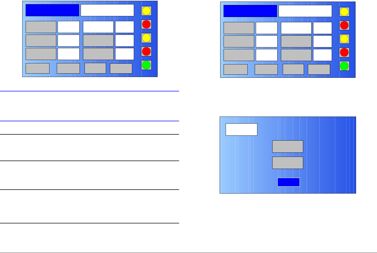
Analog Color Bar Generator B-7MTX5000 User and Technical Manual
Figure B-5: Main Screen - Typical
CAUTION Always wait a minimum of 5 seconds after
the Main screen is displayed following
power up before selecting a Preset.
Note In order to set up the analog CBG, an analog
Preset must be selected in the following step. Any
analog Preset may be selected.
12. Select any analog Preset per “Select Preset” on
page 3-24.
Note When performing steps at the MTX5000 IDU in the
following steps, option buttons may be selected
using either the touch screen or the function keys
and the SEL key.
13. Observe the Main screen is displayed. See Figure B-
6.
Channel 1 0Offset
Antenna Ant. Pol.Antenna1 H
RFU1
No RF
RF Band
Preset A Analog
4.83 & 5.8, 3MHz Vid Dev
RF Output XX
dBm
<- Status Setup Status ->
PA Off
SUM
ODU
IDU
RF
L/R
L
L
Figure B-6: Main Screen - Typical
14. Select the Setup option button and observe the Setup
screen is displayed. See Figure B-7.
Figure B-7: Setup Screen
15. Select the Radio option button and observe the Radio
screen is displayed. See Figure B-8 on page B-8.
Channel 1 0Offset
Antenna Ant. Pol.Antenna1 H
RFU1
No RF
RF Band
Preset A Analog
4.83 & 5.8, 3MHz Vid Dev
RF Output XX
dBm
<- Status Setup Status ->
PA Off
SUM
ODU
IDU
RF
L/R
L
L
Setup
User
Main
Radio
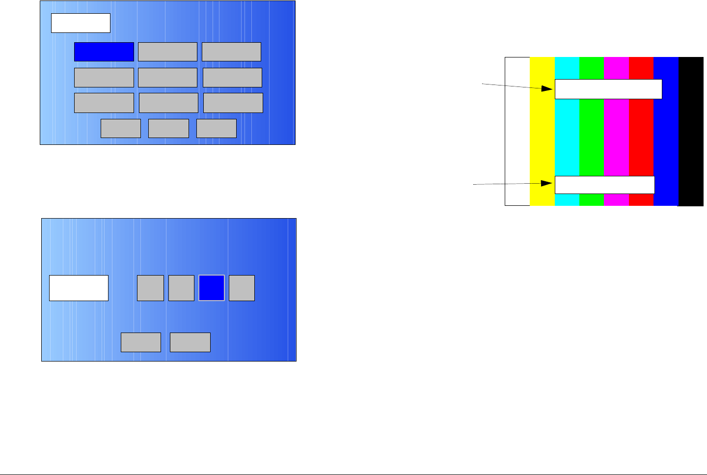
Analog Color Bar Generator B-8MTX5000 User and Technical Manual
Figure B-8: Radio Screen
16. Select the Color Bars option button and observe the
Color Bars screen is displayed. See Figure B-9.
Figure B-9: Color Bars Screen
17. Select the On option button and observe the external
monitor display.
- The video display should now have color bars similar
to Figure B-10. The text lines will contain different
characters than those shown, and may be in different
positions on the screen.
Radio
Back
Network Config Level Adjust Color Bars
Calibration
Time & Date
Change Pwd
System Info
License Key
Diagnostics
NextMain
Color Bars A GenOnOff A Stby
Back Main
- The Color Bar Generator default screen shown in
Figure B-10 will be displayed when the Color Bar
Generator is active (On).
Figure B-10: Color Bar Generator Default Screen
B.3.4 Configure Text Line A
The procedure required to configure Text Line A of the color bar
generator display is contained in the following steps.
1. Verify the “Preliminary Setup Procedure” on page B-4
has been performed.
2. Verify the Color Bar Generator default screen is
displayed. See Figure B-11 on page B-9.
Text Line A
(16 Characters
Maximum)
Text Line B
(16 Characters
Maximum)
MRC - BOSTON
REMOTE 1
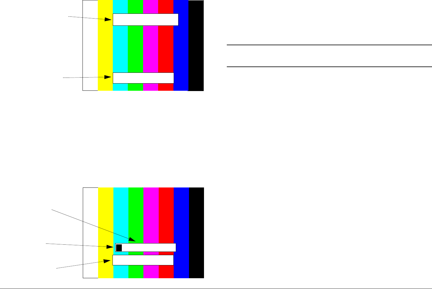
Analog Color Bar Generator B-9MTX5000 User and Technical Manual
Figure B-11: Color Bar Generator Default Screen
3. Press control switches 2 and 3 simultaneously for
approximately 5 seconds.
- The video display should now look like Figure B-12.
- The cursor will be positioned at the first character field
of Text Line A. The first character field will be
highlighted in inverse video.
- Note that the second line (TEXT LINE B) is for editing
reference only and cannot be changed.
Figure B-12: Text Line A Display
Text Line A
(16 Characters
Maximum)
Text Line B
(16 Characters
Maximum)
MRC - BOSTON
REMOTE 1
TEXT LINE B
Text Line A
(16 Characters
Maximum)
Not Editable
Inverse Video
Highlight WRC - BOSTON
M
4. The Color Bar Generator will now be in the Subset
Mode. To use the Character Mode, go to step 6.
5. To move up or down in the list of subsets, press
control switches 1 or 3 until the you reach the desired
subset. See Table B-4 on page B-18.
Note Perform step 6 thru step 8 for each character field
you wish to change.
6. Press control switch 4 to enter the Character Mode.
7. Press control switches 1 or 3 to scroll up or down in
the full character set until you reach the desired
character. See Table B-3 on page B-17.
8. Press control switch 4 to move to the next character
field. The next character field will be highlighted in
inverse video.
9. When all of Text Line A is correct, press any 3 control
switches simultaneously to save Text Line A into
memory.
10. Observe the screen flashes briefly as Text Line A is
stored. This is normal.
B.3.5 Configure Text Line B
The procedure required to configure Text Line B of the color bar
generator display is contained in the following steps.
1. Verify the “Preliminary Setup Procedure” on page B-4
has been performed.
2. Verify the Color Bar Generator default screen is
displayed. See Figure B-13 on page B-10.
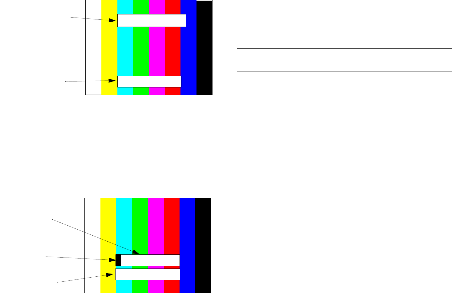
Analog Color Bar Generator B-10MTX5000 User and Technical Manual
Figure B-13: Color Bar Generator Default Screen
3. Press control switches 3 and 4 simultaneously for
approximately 5 seconds.
- The video display should now look like Figure B-14.
- The cursor will be positioned at the first character field
of Text Line B. The first character field will be
highlighted in inverse video.
- Note that the second line (TEXT LINE B) is for editing
reference only and cannot be changed.
Figure B-14: Text Line B Display
Text Line A
(16 Characters
Maximum)
Text Line B
(16 Characters
Maximum)
MRC - BOSTON
REMOTE 1
Remote 1
TEXT LINE B
Text Line B
(16 characters
Maximum)
Not Editable
Inverse Video
Highlight R
4. The Color Bar Generator will now be in the Subset
Mode. To use Character Mode go to step 6.
5. To jump up or down in the list of subsets, press control
switches 1 or 3 until the you reach the desired subset.
See Table B-4 on page B-18.
Note Perform step 6 thru step 8 for each character field
you wish to change.
6. Press control switch 4 to enter Character Mode.
7. Press control switches 1 or 3 to scroll up or down in
the full character set until you reach the desired
character. See Table B-3 on page B-17.
8. Press control switch 4 to move to the next character
field. The next character field will be highlighted in
inverse video.
9. When all of Text Line B is correct, press any 3 control
switches simultaneously to save Text Line B into
memory.
10. Observe the screen flashes briefly as Text Line A is
stored. This is normal.
B.3.6 Configure Control Line
The Control Line contains seven character fields. Each
character field controls a particular aspect of the Color Bar
Generator’s operation. Each character field can have a value of
0 through 7 only. Alphabetic characters and character subsets
are not used. See Figure B-15 on page B-11 and Table B-1 on
page B-11.
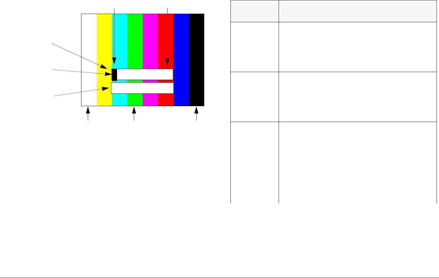
Analog Color Bar Generator B-11MTX5000 User and Technical Manual
Figure B-15: Control Line Display
2 1 3 3 4 7 0
Control Line
Control Line
(7 Characters
Maximum)
Not Editable
Inverse Video
Highlight 2
Character Fields
Color settings (fields 6 and 7)
17
037
Table B-1: Control Line Parameters
Character
Field Function
1
2When CBG is set to A GEN or A Stby, sets the
delay before the CBG will generate bars/tones
(Auto Generated) or places the MTX5000 IDU into
standby (Auto Standby). Delays can be set from 1
to 32 seconds. See Table B-5 on page B-18 for
delay values.
3Sets whether the CBG will generate bars, tones, or
both.
0 = no tones, no bars
1 = tones, no bars
2 = no tones, bars
3 = tones and bars
4Sets the position of Text Line A on the screen.
Each increment in value moves the text line down
a small amount.
0 = top of screen
7 = bottom of screen
NOTE - If the position values for Text Line A and
Text Line B are the same, Line A and Line B are in
the same location. In this case only Line A will be
visible.

Analog Color Bar Generator B-12MTX5000 User and Technical Manual
The procedure required to configure the Color Bar Generator
display control line is contained in the following steps.
1. Verify the “Preliminary Setup Procedure” on page B-4
has been performed.
2. Verify the Color Bar Generator default screen is
displayed. See Figure B-16.
5Sets the position of Text Line B on the screen.
Each increment in value moves the text line down
a small amount.
0 = top of screen
7 = bottom of screen
NOTE - If the position values for Text Line A and
Text Line B are the same, Line A and Line B are in
the same location. In this case only Line A will be
visible.
6Sets the foreground color of both text lines.
0 = white
7 = black
See Figure B-15 on page B-11 for which value
sets which color.
7Sets the foreground color of both text lines.
0 = white
7 = black
See Figure B-15 on page B-11 for which value
sets which color.
Table B-1: Control Line Parameters Figure B-16: Color Bar Generator Default Screen
3. Press control switches 2 and 4 simultaneously.
4. The video display should now look like Figure B-17 on
page B-13.
The cursor will be positioned at the first character field
of the Control Line.
- The first character field will be highlighted in inverse
video.
- Note that the second line Control Line is for editing
reference only and cannot be changed.
Text Line A
(16 Characters
Maximum)
Text Line B
(16 Characters
Maximum)
MRC - BOSTON
REMOTE 1
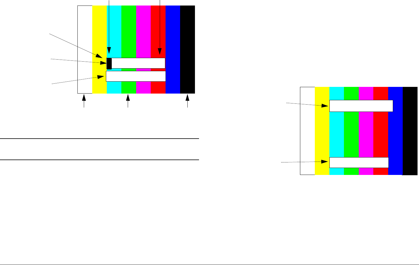
Analog Color Bar Generator B-13MTX5000 User and Technical Manual
Figure B-17: Control Line Display
Note Repeat step 5 and step 6 for each character field
you wish to change.
5. Press control switches 1 or 3 to scroll up or down
through numbers 0 through 7 until you reach the
desired number.
6. Press control switch 4 to move to the next character
field. The next character field will be highlighted in
inverse video.
7. When the Control Line is correct, press any 3 control
switches simultaneously to save the Control Line into
memory.
8. Observe the screen flashes briefly as Text Line A is
stored. This is normal.
2 1 3 3 4 7 0
Control Line
Control Line
(7 Characters
Maximum)
Not Editable
Inverse Video
Highlight 2
Character
Fields
Color settings (fields 6 and 7)
17
037
B.3.7 Check the Configuration
When all the characters and parameters have been entered,
check to be sure the Color Bar Generator is operating the way
you want it to. Perform this check before you install the
MTX5000 IDU in its rack.
Check Text Lines
1. Verify the “Preliminary Setup Procedure” on page B-4
has been performed.
2. Verify the Color Bar Generator default screen is
displayed. See Figure B-18.
Figure B-18: Color Bar Generator Default Screen
3. Verify the Color Bars screen is displayed on the
MTX5000 IDU color LCD display panel and verify the
Color Bars screen On option button is selected. See
Figure B-19 on page B-14.
Text Line A
(16 Characters
Maximum)
Text Line B
(16 Characters
Maximum)
MRC - BOSTON
REMOTE 1
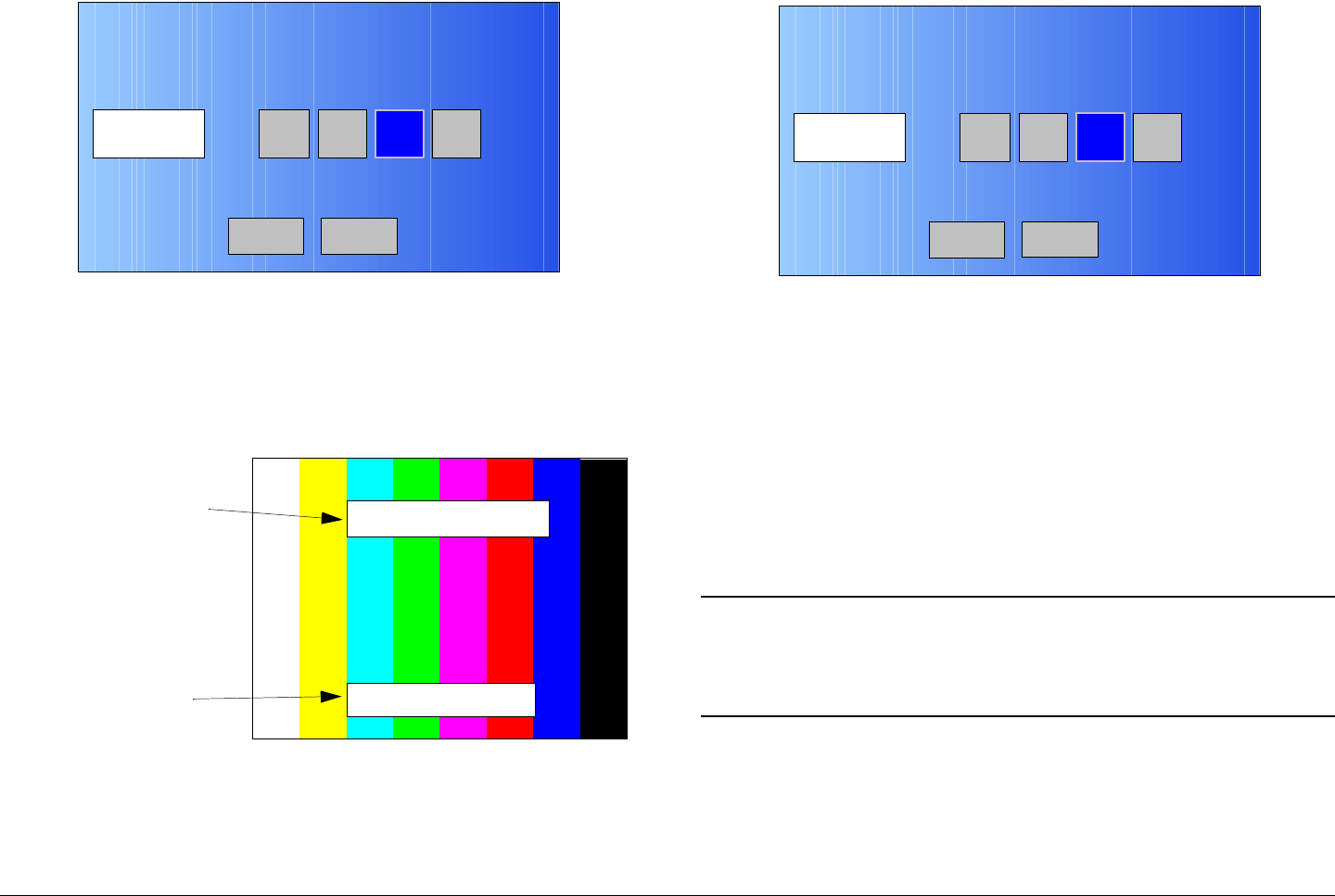
Analog Color Bar Generator B-14MTX5000 User and Technical Manual
Figure B-19: Color Bars Screen
4. The video display should display color bars similar to
Figure B-20. The text lines should be displayed where
you intended, and should contain the characters you
entered.
Figure B-20: Color Bar Generator Default Screen
Check Auto Generate
1. Select the MTX5000 IDU color LCD display panel
A Gen option using the touch screen or the function
keys. See Figure B-21.
Color Bars A GenOnOff A Stby
Back Main
Text Line A
(16 Characters
Maximum)
Text Line B
(16 Characters
Maximum)
MRC - BOSTON
REMOTE 1
Figure B-21: Color Bars Screen
2. Apply a video input to the MTX5000 IDU. If A Gen is
correctly configured, the color bars and text lines
should disappear from the video display.
3. Disconnect the video input while watching the video
monitor. After the A Gen delay you configured, the
bars and text should appear.
Check Auto Standby
1. Connect external antennas or RF dummy loads to the
MTX5000 IDU RFU 1 and RFU 2 output connectors.
Note When performing the following steps at the
MTX5000 IDU color LCD display panel, option
buttons may be selected using either the touch
screen or the function keys and the SEL key.
2. Select the MTX5000 IDU color LCD display panel
Color Bars screen A Stby option button. See
Figure B-22 on page B-15.
Color Bars A GenOnOff A Stby
Back Main
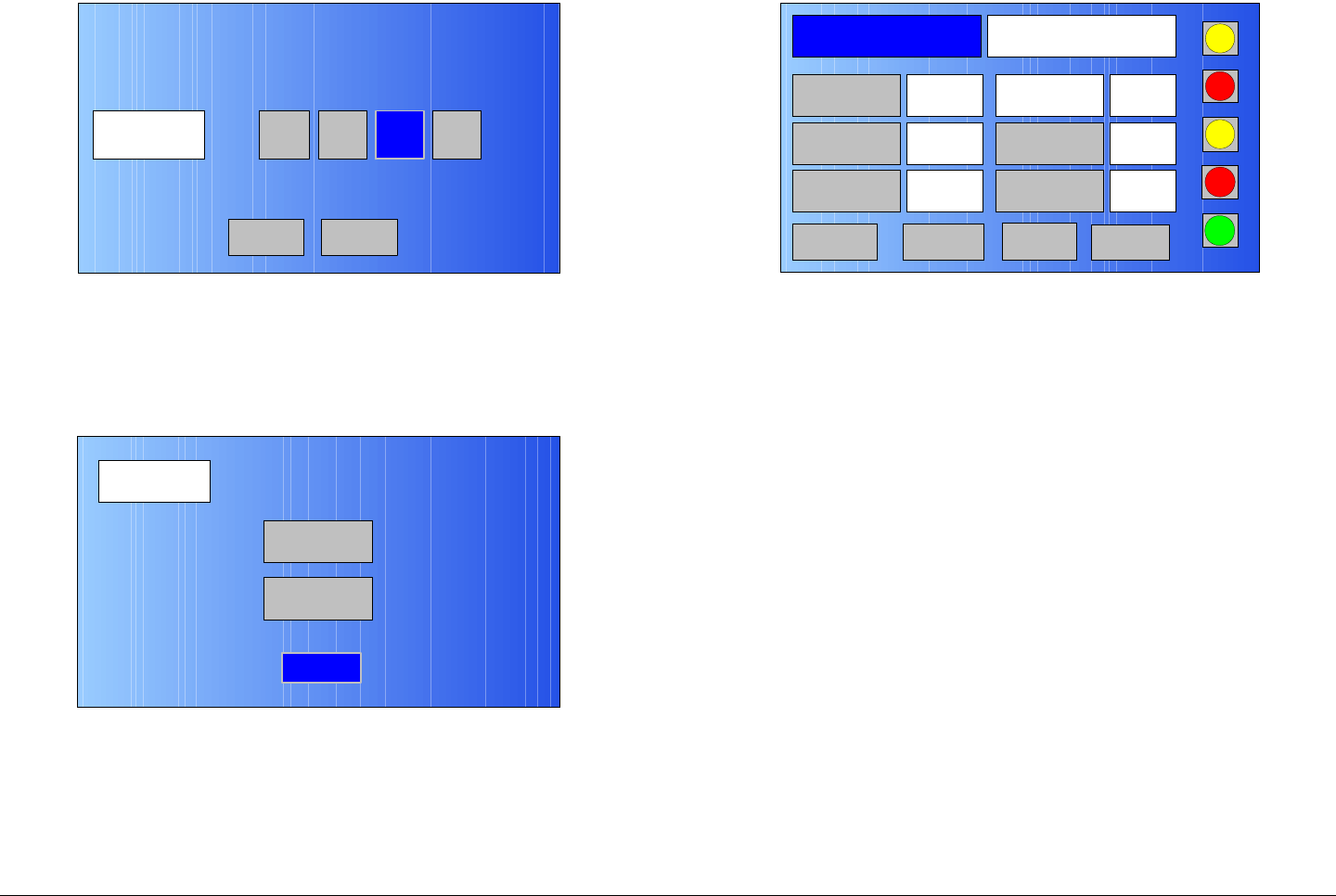
Analog Color Bar Generator B-15MTX5000 User and Technical Manual
Figure B-22: Color Bars Screen
3. Select the Color Bars screen BACK option button
and observe the Setup screen is displayed. See
Figure B-23.
Figure B-23: Setup Screen
4. Select the Setup screen Back option button and
observe the Main page is displayed. See Figure B-24.
5. Apply a video input to the MTX5000 IDU. If A Stby is
correctly configured, the color bars and text lines
should disappear from the video display.
Color Bars A GenOnOff A Stby
Back Main
Setup
User
Main
Radio
Figure B-24: Main Screen - Typical
6. Select the PA operation button and observe the status
indicator changes to green.
7. Disconnect the video input from the MTX5000 IDU.
8. The PA status indicator should now change to inactive
(grey).
9. Perform “Select Color Bar Generator Mode” on
page 3-52 to select the CGB operating mode required
for Analog Preset operations.
10. Power down the MTX5000 System. See ”Powering
the MTX5000 System” on page 3-7.
11. Disconnect the external antennas or RF dummy loads
from the RFU 1 and RFU 2 connectors.
12. Disconnect the BNC cable from the external monitor
and the test cable and disconnect the test cable from
the CBG video monitor connector J4.
13. Set the power source to off and disconnect the AC
power cable from the MTX5000 IDU rear panel AC
POWER IN connector.
14. Install the MTX5000 IDU cover panel and secure with
8 screws on the top of the unit and 2 screws at the rear
of the unit.
Channel 1 0Offset
Antenna Ant. Pol.Antenna1 H
RFU1
No RF
RF Band
Preset A Analog
4.83 & 5.8, 3MHz Vid Dev
RF Output XX
dBm
<- Status Setup Status ->
PA Off
SUM
ODU
IDU
RF
L/R
L
L
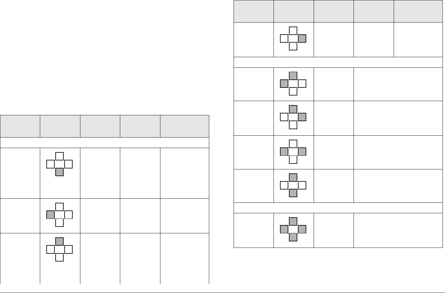
Analog Color Bar Generator B-16MTX5000 User and Technical Manual
15. Connect all cables and install the MTX5000 IDU in its
mounting rack. See ” Installation” on page 6-1.
B.4 Configuration Reference
The following tables provide additional configuration information,
including button functions, character sets, and delay values.
B.4.1 Button Functions
Table B-2 provides details of how the buttons on the Color Bar
Generator board work:
Table B-2: CBG Button Functions
Switch # Switch
Location Function First
Press Second
press
Single Button Functions
1Scroll
down Scroll
down one
character
or
character
subset
2Cursor left Switches
to
character
mode
moves cursor
to next
character
field to left
3Scroll up Scroll up
one
character
or
character
subset
24
3
1
24
3
1
24
3
1
4Cursor
right Switches
to
character
mode
Moves cursor
to next
character
field to right
Two Button Functions
SW2 &
SW3
Moves cursor to first
character in Text Line A
SW3 &
SW4
Moves cursor to first
character in Text Line B
SW2 &
SW4
Moves cursor to first
character in Control Line
SW1 &
SW3
Hides/unhides characters.
CBG must be in subset
mode first.
Three Key Functions
Press any
3 keys
Saves the current
configuration to memory.
Video flashes briefly when
configuration is stored.
Table B-2: CBG Button Functions (Continued)
Switch # Switch
Location Function First
Press Second
press
24
3
1
24
3
1
24
3
1
24
3
1
24
3
1
24
3
1
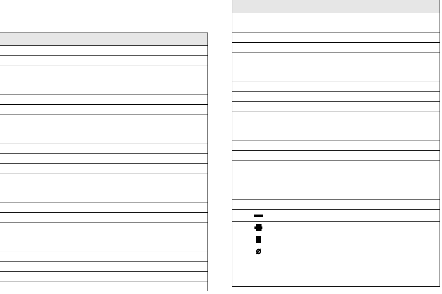
Analog Color Bar Generator B-17MTX5000 User and Technical Manual
B.4.2 Full Character Set
Table B-3 contains all of the characters the Color Bar Generator
can display. .
Table B-3: Full Character Set
Character Subset # Note
0space
A1
B2
C3
D4
E5
F6
G7
H0
I1
J2
K3
L4
M5
N6
O7
P0
Q1
R2
S3
T4
U5
V6
W7
X0
Y1
Z2
!3exclamation
.4period
,5comma
=6equals
^7caret
(0left parenthesis
)1right parenthesis
–2hyphen
_3underline
+4plus
<5less than
>6greater than
l7vertical bar
/0forward slash
‘1apostrophe
\2back slash
:3colon
;4semicolon
5half height bullet
6full height bullet
7solid block
0space
11
22
33
Table B-3: Full Character Set (Continued)
Character Subset # Note
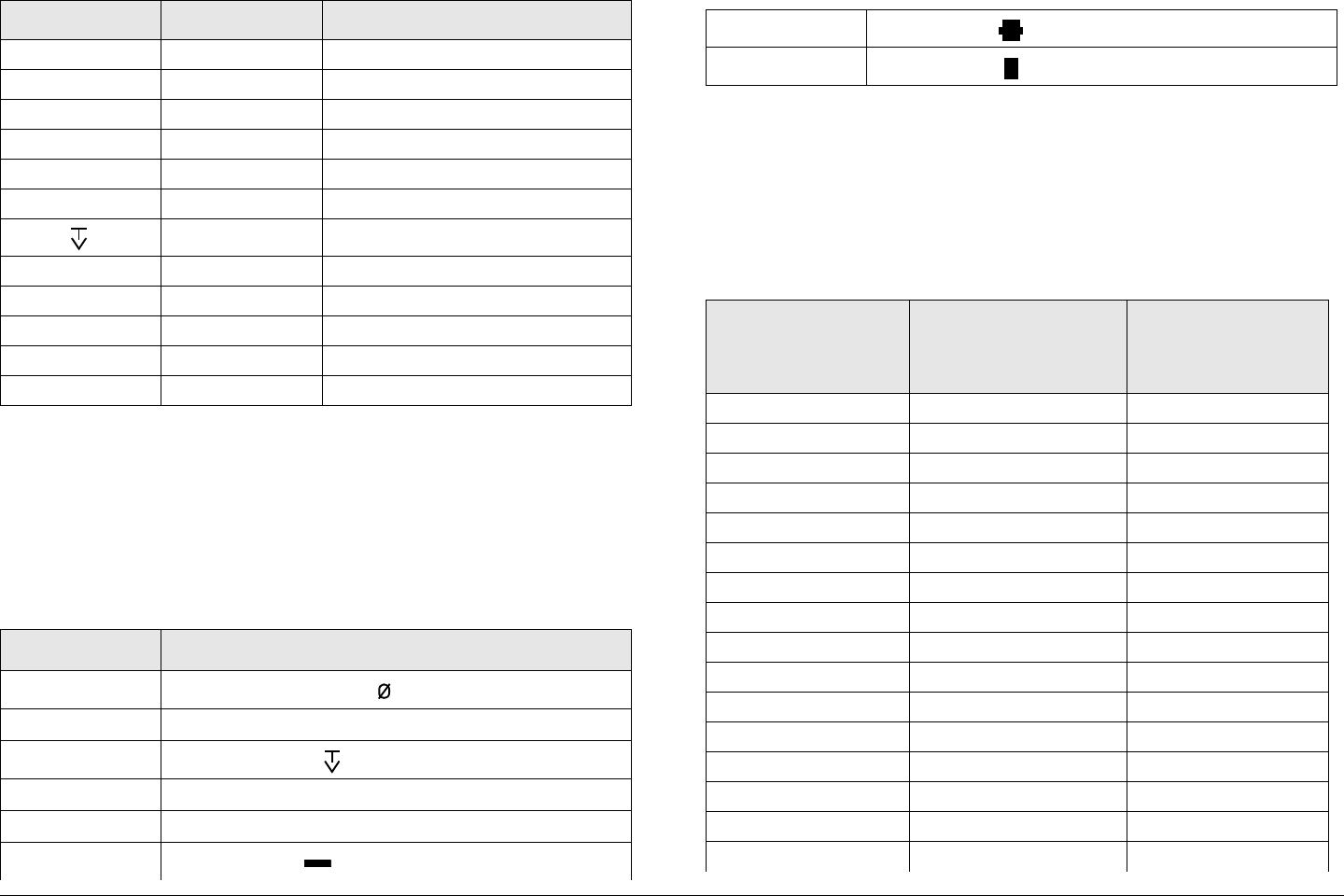
Analog Color Bar Generator B-18MTX5000 User and Technical Manual
B.4.3 Character Subsets
Table B-4 provides the character subsets the Color Bar
Generator uses. Note: the subsets are also shown in Table B-3
on page B-17.
Table B-4: Character Subsets
44
55
66
77
80
91
2T above a V
#3number
$4dollars
%5percent
&6ampersand (and)
*7asterisk
Subset # Character
0(space), H, P, X, [(], /, , 8
1A, I, Q, Y, (, [‘], 1, 9
2B, J, R, Z,), \, 2,
3C, K, S,!, _, [:], 3, #
4D, L, T, [.], _, [;], 4, $
5E, M, U, [,], +, , 5,%
Table B-3: Full Character Set (Continued)
Character Subset # Note
B.4.4 Delay Values
Table B-5 provides the delay in seconds corresponding to each
value in Control Line fields 1 and 2. Note that the delay values
repeat themselves so that a setting of 4,0 results in the same
delay as a setting of 0,0 (1 second).
6F, N, V, =, <, , 6, &
7G, O, W, ^, |, , 7, *
Table B-5: Delay Values
Field
Position
1
Field
Position
2
Delay
in
Seconds
0 0 1
0 1 2
0 2 3
0 3 4
0 4 5
0 5 6
0 6 7
0 7 8
1 0 9
1 1 10
1 2 11
1 3 12
1 4 13
1 5 14
1 6 15
1 7 16
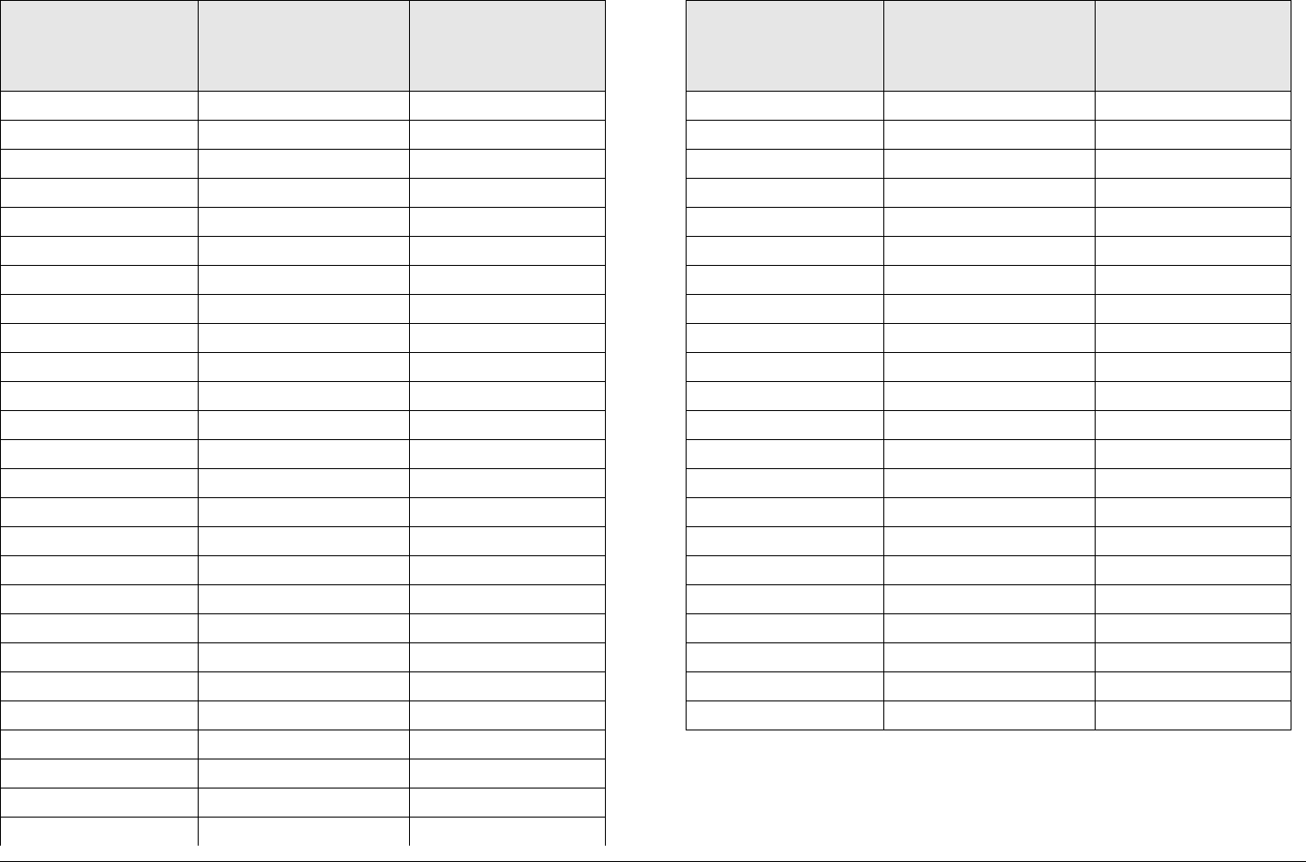
Analog Color Bar Generator B-19MTX5000 User and Technical Manual
2 0 17
2 1 18
2 2 19
2 3 20
2 4 21
2 5 22
2 6 23
2 7 24
3 0 25
3 1 26
3 2 27
3 3 28
3 4 29
3 5 30
3 6 31
3 7 32
4 0 1
4 1 2
4 2 3
4 3 4
4 4 5
4 5 6
4 6 7
4 7 8
5 0 9
5 1 10
Table B-5: Delay Values (Continued)
Field
Position
1
Field
Position
2
Delay
in
Seconds
5 2 11
5 3 12
5 4 13
5 5 14
5 6 15
5 7 16
6 0 17
6 1 18
6 2 19
6 3 20
6 4 21
6 5 22
6 6 23
6 7 24
7 0 25
7 1 26
7 2 27
7 3 28
7 4 29
7 5 30
7 6 31
7 7 32
Table B-5: Delay Values (Continued)
Field
Position
1
Field
Position
2
Delay
in
Seconds

Analog Color Bar Generator B-20MTX5000 User and Technical Manual
This page intentionally left blank.

Index Index-1MTX5000 User and Technical Manual
Index
A
About This Manual . . . . . . . . . . . . . . . . . . . . . . . . . . . Notices-i
AC power
MTX5000 IDU . . . . . . . . . . . . . . . . . . . . . . . . . . . . . . .2-7
AC power cable . . . . . . . . . . . . . . . . . . . . . . . . . . . . . . . . . . .6-4
advanced features . . . . . . . . . . . . . . . . . . . . . . . . . . . . . . . . .8-2
Advanced Operations . . . . . . . . . . . . . . . . . . . . . . . . . . . . . .5-1
Advanced operations
add licensed options . . . . . . . . . . . . . . . . . . . . . . . .5-117
configuring your MTX5000 IDU . . . . . . . . . . . . . . . . . .5-3
create a new custom analog Preset . . . . . . . . . 5-7, 5-73
create a new custom digital ASI Preset . . . . . . . . . .5-82
create a new custom digital COFDM Preset . . . . . . .5-77
create a new custom digital COFDM Preset configuration
5-17
create a new custom digital DVB-S Preset . . . . . . . .5-91
create a new custom digital DVB-S Preset configuration
5-47
create a new custom digital IP Preset . . . . . . . . . . . .5-96
create a new custom digital LMS-T Preset . . . . . . . .5-86
default password . . . . . . . . . . . . . . . . . . . . . . . . . . . . .5-4
Firmware updates . . . . . . . . . . . . . . . . . . . . . . . . . .5-114
license manager . . . . . . . . . . . . . . . . . . . . . . . . . . .5-117
load custom Preset configuration settings from file 5-106
local mode password control . . . . . . . . . . . . . . . . . . .5-4
password control . . . . . . . . . . . . . . . . . . . . . . . . . . . . .5-1
restore custom Presets to factory defaults . . . . . . .5-102
save current Preset configuration settings to a file .5-104
set network addresses for remote operation . . . . . .5-109
Software updates
factory licensed options . . . . . . . . . . . . . . . . . . .5-117
memory stick . . . . . . . . . . . . . . . . . . . . .5-102, 5-114
thumb drive . . . . . . . . . . . . . . . . . . . . . .5-102, 5-114
USB flash drive . . . . . . . . . . . . . . . . . . . . . . . . 5-114
System Rules . . . . . . . . . . . . . . . . . . . . . . . . . . . . . . 5-2
update an existing analog Preset configuration . . . . 5-73
update an existing digital ASI Preset configuration . 5-82
update an existing digital COFDM Preset configuration 5-
17, . . . . . . . . . . . . . . . . . . . . . . . . . . . . . . . . . . . 5-77
update an existing digital DVB-S Preset configuration 5-
47, . . . . . . . . . . . . . . . . . . . . . . . . . . . . . . . . . . . 5-91
update an existing digital IP Preset configuration . . 5-96
update an existing digital LMS-T Preset configuration 5-
86
update an existing Preset configuration . . . . . . . . . . 5-7
analog CBG
Text lines and parameters . . . . . . . . . . . . . . . . . . . . . B-2
Analog Color Bar Generator . . . . . . . . . . . . . . . . . . . . . . . . . B-1
Audio Connections . . . . . . . . . . . . . . . . . . . . . . . . . . . . . . . 6-24
C
Cabling
mobile installations . . . . . . . . . . . . . . . . . . . . . . . . . . 6-3
CAUTIONS . . . . . . . . . . . . . . . . . . . . . . . . . . . . . . . . . Notices-iv
Character Set, CBG . . . . . . . . . . . . . . . . . . . . . . . . . . . . . . B-17
Character Subsets, CBG . . . . . . . . . . . . . . . . . . . . . . . . . . B-18
Color Bar Generator
Button Functions . . . . . . . . . . . . . . . . . . . . . . . . . . . B-16
Character Subsets . . . . . . . . . . . . . . . . . . . . . . . . . . B-18
Check AUTOGEN . . . . . . . . . . . . . . . . . . . . . . . . . . B-14
Check AUTOSTDBY . . . . . . . . . . . . . . . . . . . . . . . . B-14
Check Text Lines . . . . . . . . . . . . . . . . . . . . . . . . . . . B-13
Check the Configuration . . . . . . . . . . . . . . . . . . . . . B-13
Configuration . . . . . . . . . . . . . . . . . . . . . . . . . . . . . . . B-2
Character Mode . . . . . . . . . . . . . . . . . . . . . . . . . . B-4
character mode . . . . . . . . . . . . . . . . . . . . . . . . . . B-4

Index Index-2MTX5000 User and Technical Manual
Control Line . . . . . . . . . . . . . . . . . . . . . . . . . . . . B-10
Entering Characters . . . . . . . . . . . . . . . . . . . . . . . B-4
Hiding Characters . . . . . . . . . . . . . . . . . . . . . . . . B-4
Setup . . . . . . . . . . . . . . . . . . . . . . . . . . . . . . . . . . B-4
Text Line A . . . . . . . . . . . . . . . . . . . . . . . . . . . . . B-8
Text Line B . . . . . . . . . . . . . . . . . . . . . . . . . . . . . B-9
Configuration Reference . . . . . . . . . . . . . . . . . . . . . B-16
Button Functions . . . . . . . . . . . . . . . . . . . . . . . . B-16
Character Subsets . . . . . . . . . . . . . . . . . . . . . . . B-18
Full Character Set . . . . . . . . . . . . . . . . . . . . . . . B-17
Configure Text Line A . . . . . . . . . . . . . . . . . . . . . . . . B-8
Configure Text Line B . . . . . . . . . . . . . . . . . . . . . . . . B-9
Configure the Control Line . . . . . . . . . . . . . . . . . . . B-10
control switches . . . . . . . . . . . . . . . . . . . . . . . . . . . . B-4
Delay Values . . . . . . . . . . . . . . . . . . . . . . . . . . . . . . B-18
Full Character Set . . . . . . . . . . . . . . . . . . . . . . . . . . B-17
Functions . . . . . . . . . . . . . . . . . . . . . . . . . . . . . . . . . B-1
functions . . . . . . . . . . . . . . . . . . . . . . . . . . . . . . . . . . B-1
hide characters . . . . . . . . . . . . . . . . . . . . . . . . . . . . . B-4
Operating Modes . . . . . . . . . . . . . . . . . . . . . . . . . . . B-1
operating modes . . . . . . . . . . . . . . . . . . . . . . . . . . . . B-1
subset mode . . . . . . . . . . . . . . . . . . . . . . . . . . . . . . . B-4
Technical Background . . . . . . . . . . . . . . . . . . . . . . . B-2
Composite Video (CV) . . . . . . . . . . . . . . . . . . . . . . . . . . . . . .8-2
Connections
IDU Rear Panel . . . . . . . . . . . . . . . . . . . . . . . . . . . . .6-19
Control Line . . . . . . . . . . . . . . . . . . . . . . . . . . . . . . . . . . . . B-10
Conventions . . . . . . . . . . . . . . . . . . . . . . . . . . . . . . . Notices-iv
Copyright . . . . . . . . . . . . . . . . . . . . . . . . . . . . . . . . . . . Notices-i
D
Damage in Shipment . . . . . . . . . . . . . . . . . . . . . . . . . . . . . . .6-2
default password . . . . . . . . . . . . . . . . . . . . . . . . . . . . . . . . . .5-4
Documents
Ordering . . . . . . . . . . . . . . . . . . . . . . . . . . . . . . . . . . .1-1
E
E-mailFeedback . . . . . . . . . . . . . . . . . . . . . . . . . . . . . . . . . . 1-2
Technical Support team . . . . . . . . . . . . . . . . . . . . . . . 1-2
F
factory default analog Presets . . . . . . . . . . . . . . . . . . .5-7, 5-74
factory default digital ASI Presets . . . . . . . . . . . . . . . . . . . 5-82
factory default digital COFDM Presets . . . . . . . . . . . . . . . . 5-77
factory default digital DVB-S Presets . . . . . . . . . . . . . . . . . 5-91
factory default digital IP Presets . . . . . . . . . . . . . . . . . . . . . 5-96
factory default digital LMS-T Presets . . . . . . . . . . . . . . . . . 5-86
factory default Presets . . . . . . . . . . . . . . . . . . . . . . . . . . . . . 5-3
Feedback . . . . . . . . . . . . . . . . . . . . . . . . . . . . . . . . . . . . . . . 1-2
G
Grounding . . . . . . . . . . . . . . . . . . . . . . . . . . . . . . . . . . . . . . 6-5
H
How to Use This Manual . . . . . . . . . . . . . . . . . . . . . . . . . . . 1-2
I
Installation . . . . . . . . . . . . . . . . . . . . . . . . . . . . . . . . . . . . . . 6-1
AES/EBU connections . . . . . . . . . . . . . . . . . . . . . . . 6-24
AUDIO 1 thru AUDIO 4 connections . . . . . . . . . . . . 6-24
Cabling . . . . . . . . . . . . . . . . . . . . . . . . . . . . . . . .6-3, 6-4
Checks before power-up . . . . . . . . . . . . . . . . . . . . . 6-27
connections to the IDU . . . . . . . . . . . . . . . . . . . . . . 6-16
define wiring harness . . . . . . . . . . . . . . . . . . . . . . . . . 6-5
Defining the Wiring Harness
Determine the Size of Harness Required . . . . . . . 6-9
Equipment Rack . . . . . . . . . . . . . . . . . . . . . . . . . . . . 6-2
Ethernet . . . . . . . . . . . . . . . . . . . . . . . . . . . . . . . . . . 6-27
function cables . . . . . . . . . . . . . . . . . . . . . . . . . . . . . . 6-7
grounding . . . . . . . . . . . . . . . . . . . . . . . . . . . . . . . . . . 6-5

Index Index-3MTX5000 User and Technical Manual
Initial power-up . . . . . . . . . . . . . . . . . . . . . . . . . . . . .6-27
mobile applications . . . . . . . . . . . . . . . . . . . . . . . . . . .6-2
Moisture . . . . . . . . . . . . . . . . . . . . . . . . . . . . . . . . . . .6-3
moisture . . . . . . . . . . . . . . . . . . . . . . . . . . . . . . . . . . .6-3
mount ODU . . . . . . . . . . . . . . . . . . . . . . . . . . . . . . . .6-13
mounting one ODU . . . . . . . . . . . . . . . . . . . . . . . . . .6-14
Mounting the MRX4000 . . . . . . . . . . . . . . . . . . . . . . .6-3
optional Remote Access Subnotebook PC . . . . . . . .6-26
pinouts of AES/EBU channel 1 and 2 digital connectors
6-25
pinouts of AUDIO 1 thru 4 analog connectors . . . . .6-25
remote control option . . . . . . . . . . . . . . . . . . . . . . . .6-26
RF and DC power cabling . . . . . . . . . . . . . . . . . . . . . .6-5
RFU POWER OUT connector pinouts . . . . . . . . . . .6-26
RJ-45 crossover cable . . . . . . . . . . . . . . . . . . . . . . .6-26
Site Preparation . . . . . . . . . . . . . . . . . . . . . . . . . . . . .6-2
Triax connectors . . . . . . . . . . . . . . . . . . . . . . . . . 6-6, A-1
Ventilation . . . . . . . . . . . . . . . . . . . . . . . . . . . . . . . . . .6-3
ventilation . . . . . . . . . . . . . . . . . . . . . . . . . . . . . . . . . .6-3
Installing the MRX4000 . . . . . . . . . . . . . . . . . . . . . . . . . . . . .6-2
L
license manager . . . . . . . . . . . . . . . . . . . . . . . . . . . . . . . .5-117
licensed options . . . . . . . . . . . . . . . . . . . . . . . . . . . . . . . . .5-117
M
Mast Top Connections . . . . . . . . . . . . . . . . . . . . . . . . . . . .6-16
Mounting the MTX5000 IDU . . . . . . . . . . . . . . . . . . . . . . . . .6-3
Mounting the ODU . . . . . . . . . . . . . . . . . . . . . . . . . . . . . . . .6-14
MRC Customer Service . . . . . . . . . . . . . . . . . . . . . . . . . 1-1, 6-2
Business Hours . . . . . . . . . . . . . . . . . . . . . . . . . . . . . .1-1
Telephone . . . . . . . . . . . . . . . . . . . . . . . . . . . . . . . . . .1-1
MRC Technical Support
Business Hours . . . . . . . . . . . . . . . . . . . . . . . . . . . . . .1-1
E-mail . . . . . . . . . . . . . . . . . . . . . . . . . . . . . . . . . . . . .1-1
Telephone . . . . . . . . . . . . . . . . . . . . . . . . . . . . . . . . . .1-1
MTX5000
components and capabilities . . . . . . . . . . . . . . . . . . . 2-1
configurations . . . . . . . . . . . . . . . . . . . . . . . . . . . . . . 2-1
Menu Screens . . . . . . . . . . . . . . . . . . . . . . . . . . . . . 3-10
O
ODU Mounting . . . . . . . . . . . . . . . . . . . . . . . . . . . . . . . . . 6-14
On-Line Viewing . . . . . . . . . . . . . . . . . . . . . . . . . . . . . Notices-v
ordering a license key from MRC . . . . . . . . . . . . . . . . . . . 5-118
P
passwords . . . . . . . . . . . . . . . . . . . . . . . . . . . . . . . . . . . . . . 5-4
personal password . . . . . . . . . . . . . . . . . . . . . . . . . . . . . . . . 5-4
Power Connections . . . . . . . . . . . . . . . . . . . . . . . . . . . . . . . 6-4
Additional Powering Notes . . . . . . . . . . . . . . . . . . . . 6-4
Power Requirements . . . . . . . . . . . . . . . . . . . . . . . . . . . . . . 6-4
IDU Power Consumption . . . . . . . . . . . . . . . . . . . . . . 6-4
ODU Power Consumption (Dual ODU System) . . . . 6-4
Standard ODU Power Consumption . . . . . . . . . . . . . 6-4
Supply Voltage . . . . . . . . . . . . . . . . . . . . . . . . . . . . . 6-4
power requirements . . . . . . . . . . . . . . . . . . . . . . . . . . . . . . . 6-4
Preparing for Operation . . . . . . . . . . . . . . . . . . . . . . . . . . . . 3-7
Proprietary Material . . . . . . . . . . . . . . . . . . . . . . . . . . . Notices-i
Q
Quality Certification . . . . . . . . . . . . . . . . . . . . . . . . . . . Notices-i
R
Radio IP, Subnet Mask, Gateway, and DNS Server addresses
5-109
Replacement Parts . . . . . . . . . . . . . . . . . . . . . . . . . . . . . . . . 7-1
External Cables . . . . . . . . . . . . . . . . . . . . . . . . . . . . . 7-1
S
SD Serialized Digital Interface video . . . . . . . . . . . . . . . . . . 8-2
site power requirements . . . . . . . . . . . . . . . . . . . . . . . . . . . . 6-4

Index Index-4MTX5000 User and Technical Manual
Site preparation . . . . . . . . . . . . . . . . . . . . . . . . . . . . . . . . . .6-14
Symbols Used . . . . . . . . . . . . . . . . . . . . . . . . . . . . . . .Notices-v
T
Technical Support . . . . . . . . . . . . . . . . . . . . . . . . . . . . . . . . .1-1
Text Line A . . . . . . . . . . . . . . . . . . . . . . . . . . . . . . . . . . . . . B-8
Text Line B . . . . . . . . . . . . . . . . . . . . . . . . . . . . . . . . . . . . . B-9
Theory of Operation . . . . . . . . . . . . . . . . . . . . . . . . . . . . . . .8-1
analog FM transmission . . . . . . . . . . . . . . . . . . . . . . .8-1
Digital Video Broadcasting - Terrestrial (DVB-T) . . . .8-1
encoding SD and HD video . . . . . . . . . . . . . . . . . . . . .8-2
Frequency-Shift Keying (FSK) modem . . . . . . . . . . . .8-1
IDU and the ODU . . . . . . . . . . . . . . . . . . . . . . . . . . . .8-1
Modulation Error Ratio/Error Vector Magnitude (MER/
EVM) . . . . . . . . . . . . . . . . . . . . . . . . . . . . . . . . . . .8-1
MRX4000 internal software . . . . . . . . . . . . . . . . . . . . .8-3
MTX5000 ODU . . . . . . . . . . . . . . . . . . . . . . . . . . . . . .8-5
MTX5000 system architecture . . . . . . . . . . . . . . . . . .8-1
MTX5000 user interface . . . . . . . . . . . . . . . . . . . . . . .8-2
ODU functional block diagram . . . . . . . . . . . . . . . . . .8-5
ODU output . . . . . . . . . . . . . . . . . . . . . . . . . . . . . . . . 8-3
remote operation . . . . . . . . . . . . . . . . . . . . . . . . . . . . 8-2
RF transmission . . . . . . . . . . . . . . . . . . . . . . . . . . . . . 8-1
user interface . . . . . . . . . . . . . . . . . . . . . . . . . . . . . . . 8-1
Troubleshooting . . . . . . . . . . . . . . . . . . . . . . . . . . . . . . . . . . 4-1
U
Unpacking . . . . . . . . . . . . . . . . . . . . . . . . . . . . . . . . . . . . . . 6-1
update firmware . . . . . . . . . . . . . . . . . . . . . . . . . . . . . . . . 5-114
W
WARNINGS . . . . . . . . . . . . . . . . . . . . . . . . . . . . . . . . Notices-iv
Warranty statement . . . . . . . . . . . . . . . . . . . . . . . . . . . . . . 6-29
Waste Electrical and Electronic Equipment . . . . . . . . Notices-v
Wayside Data
Compatibility . . . . . . . . . . . . . . . . . . . . . . . . . . . . . . 6-24
What This Manual Covers . . . . . . . . . . . . . . . . . . . . . . . . . . 1-2
Wiring Harness
Determine Size . . . . . . . . . . . . . . . . . . . . . . . . . . . . . 6-9