Microwave Radio Communications PTX127T1CG 13GHz PTX-PRO User Manual User and Tech Manual
Microwave Radio Communications LLC 13GHz PTX-PRO User and Tech Manual
UserManual.wiki
>
Microwave Radio Communications
>
PTX127T1CG User Manual
Manual
Navigation menu
Upload a User Manual
Namespaces
Wiki Guide
HTML
PDF
Info
Views
User Manual
Discussion / Help
Navigation
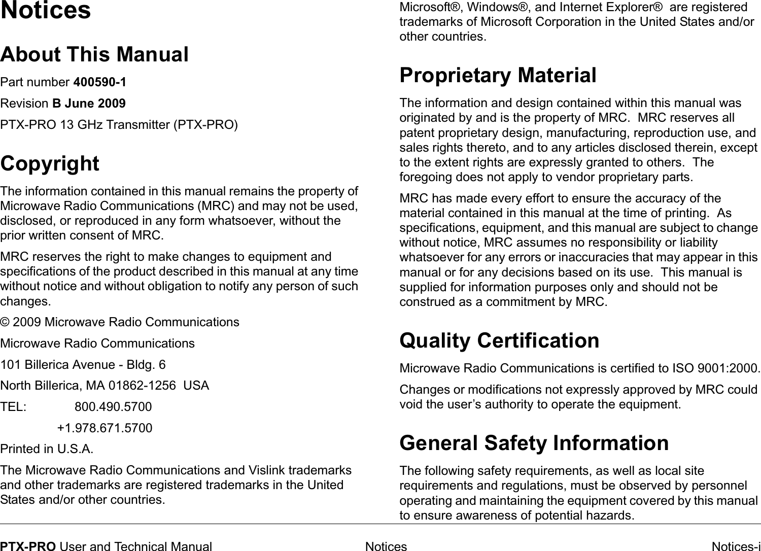
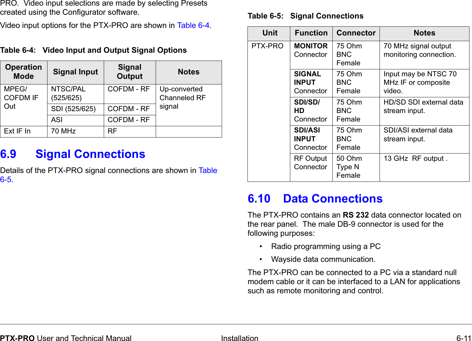
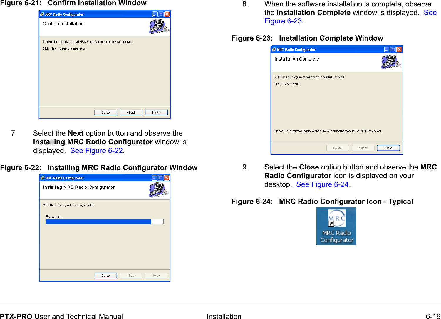
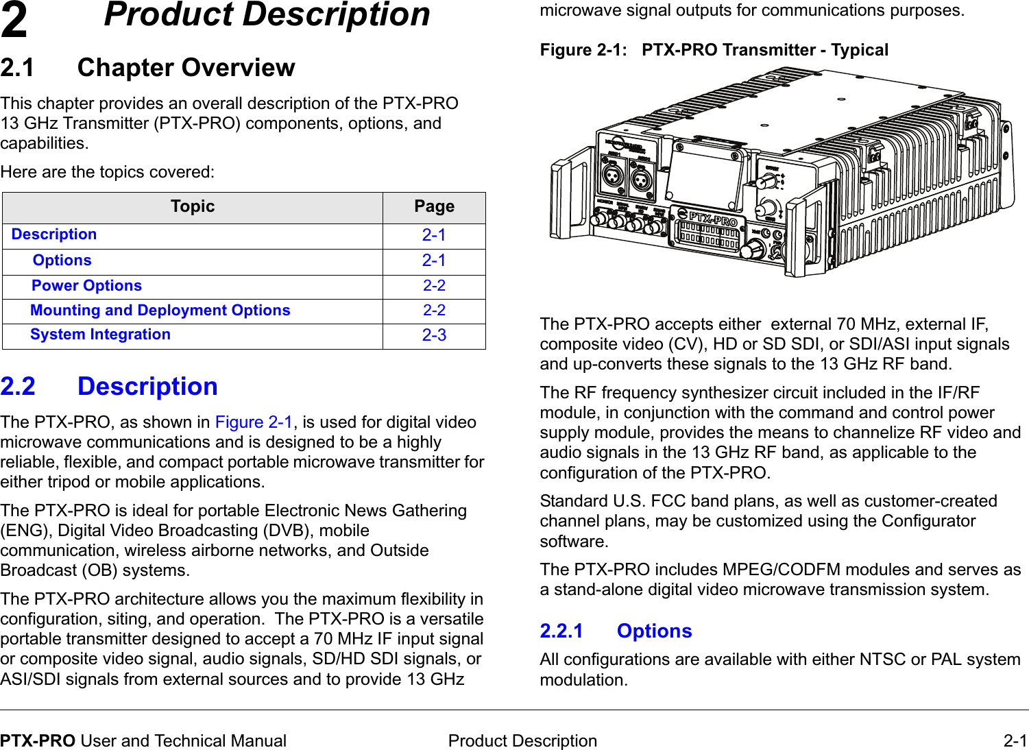
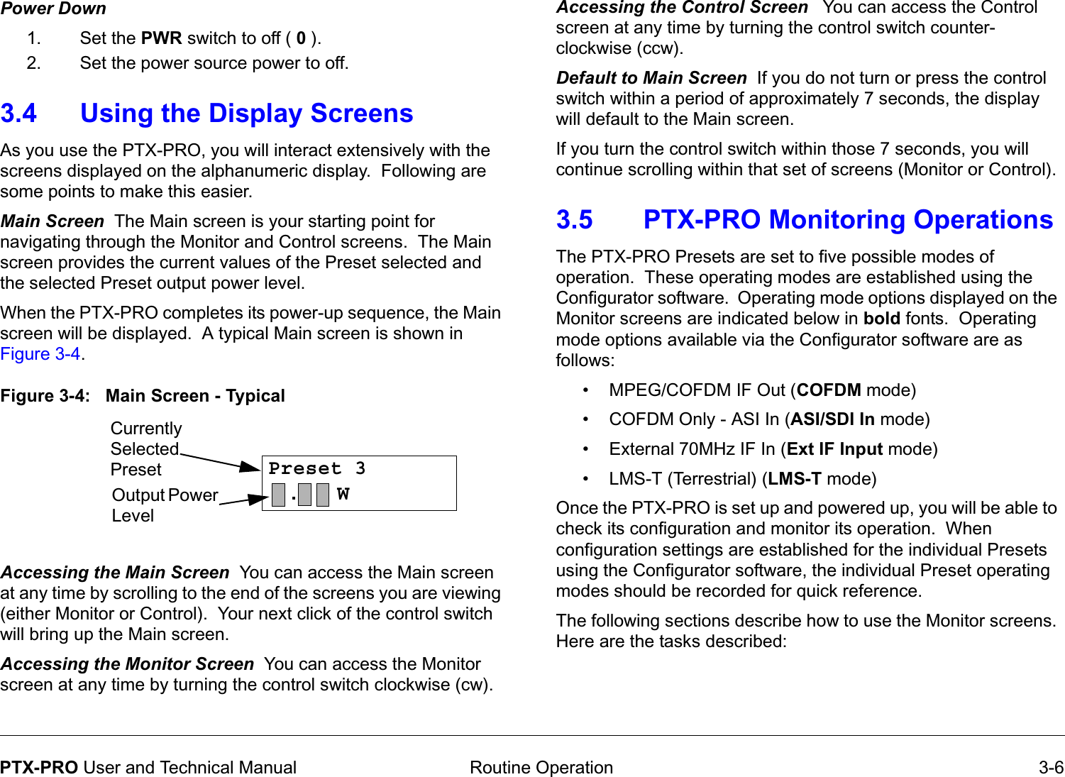
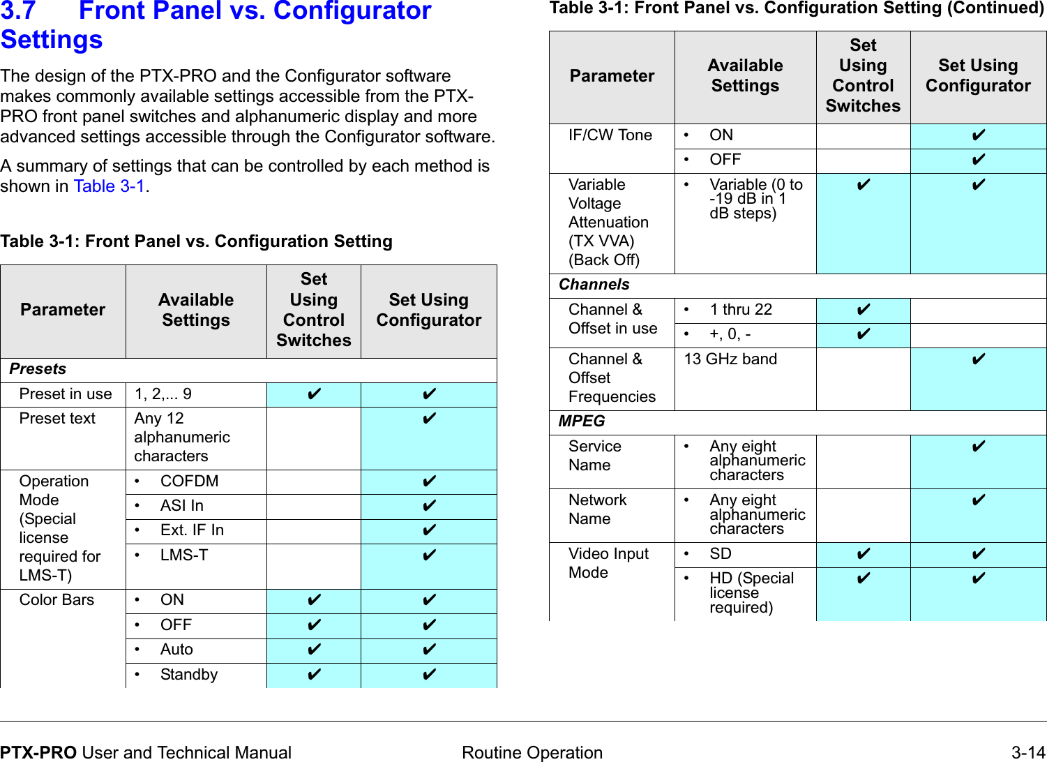
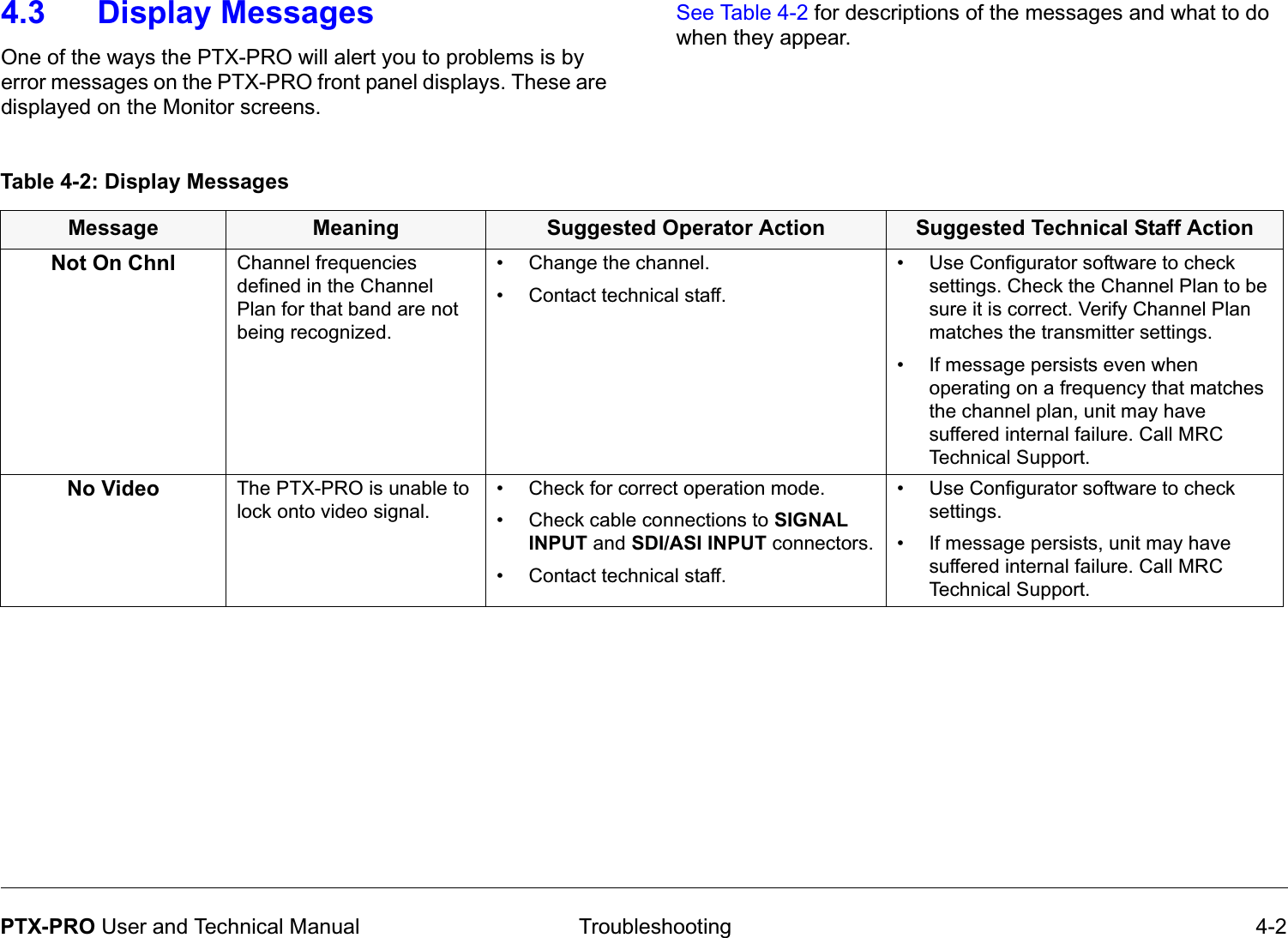
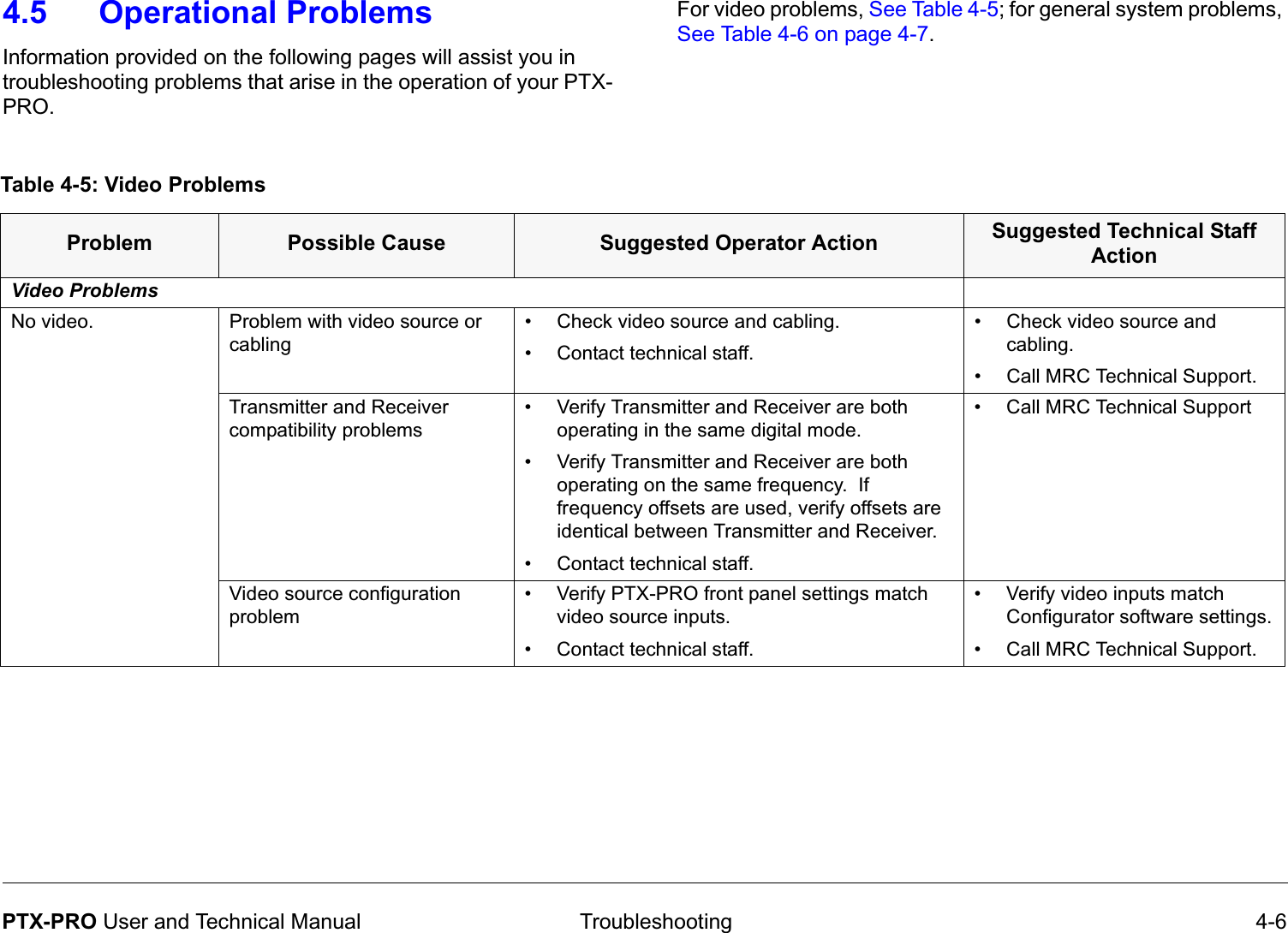
![Notices Notices-iiiPTX-PRO User and Technical Manual1. [P] RF power input. Convert watts to milliwatts = Watts * 10002. [G] Antenna gain dBi. Convert to numeric gain = Antilog (dBi/10)3. [EIRP] Multiply P * G 4. [R] Convert centimeters to feet = Centimeters * .03285. Square R6. Multiply R² * 4π7. [S] Divide (R² * 4π) into EIRPS = Power Density in milliwatts per square centimeters. Note: At frequencies above 1500 MHz, S must not be greater than 1ReferenceFCC OET Bulletin 65, August 1997 - Evaluating Compliance with FCC Guidelines for Human Exposure to Radio Frequency Electromagnetic FieldsThe example shown in Figure 1 is a typical graph for an MRC PTX-PRO 13 GHz Transmitter and shows the permissible exposure distance for various antennas. Graphs and data will vary, based on the actual transmitter, output power, frequency, and antenna utilized. The plot provides the permissible output of the transmitter for digital modulationMRC, in accordance with the requirements set forth by the FCC, provides this information as a guide to the user. It is assumed that the users of this equipment are licensed and qualified to operate the equipment per the guidelines and recommendations contained within the product user guides and in accordance with any FCC rules that may apply.Figure 1: Digital ModulationThe following table reflects the graphic representations above.Table 1: Antenna Gain (dBi)Minimum Distance from Antenna (cm)Minimum Distance from Antenna (inch)08 3.155 45 17.7116 51 20.0720 80 31.4935 449 176.73](https://usermanual.wiki/Microwave-Radio-Communications/PTX127T1CG/User-Guide-1143670-Page-5.png)
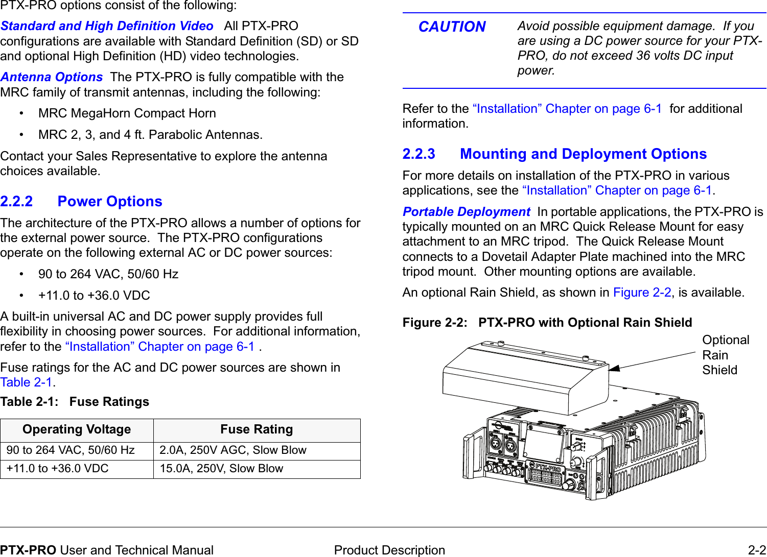

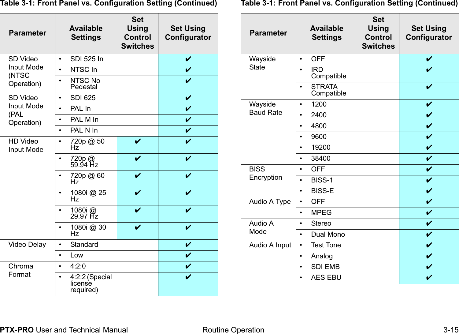
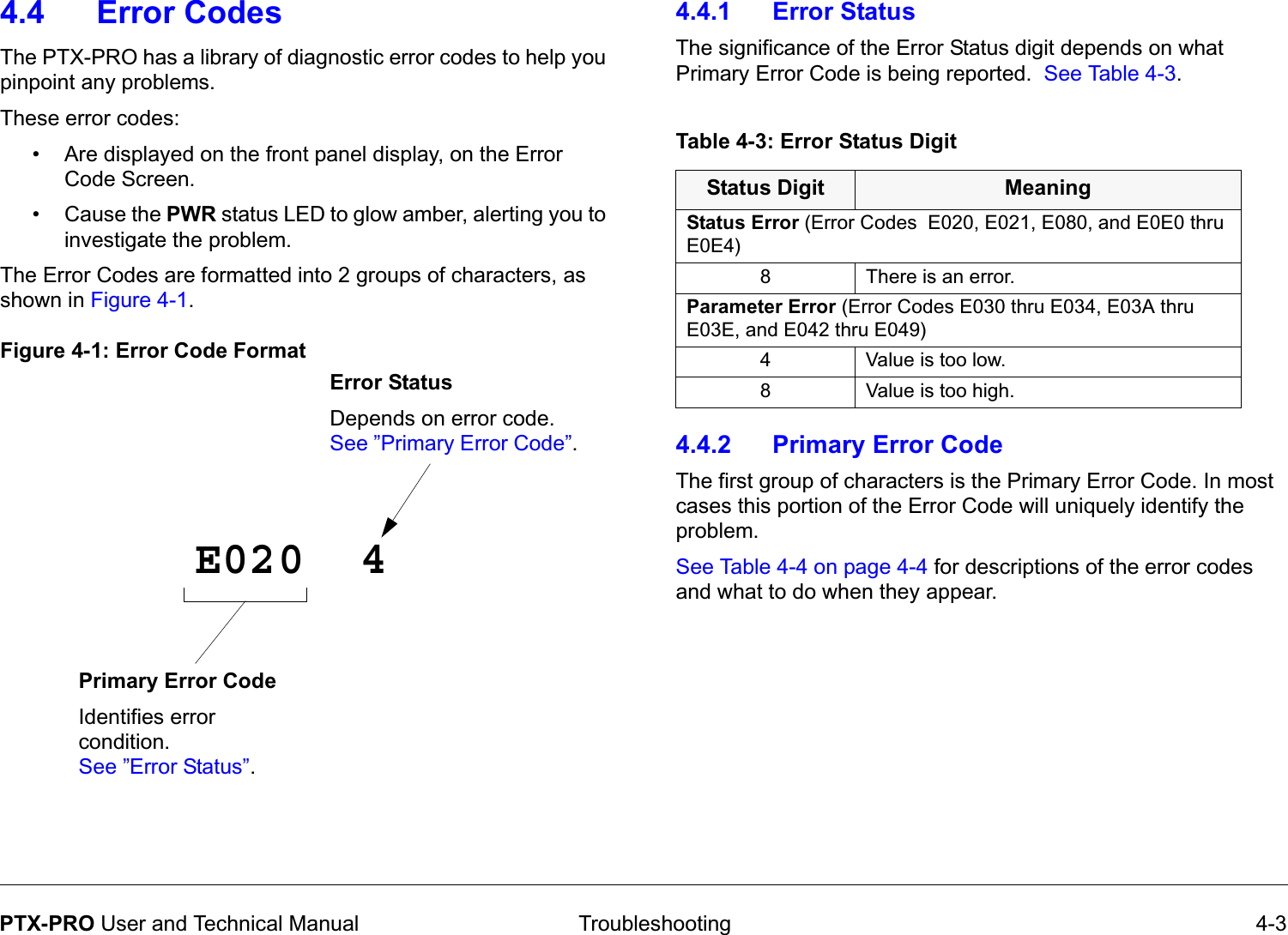
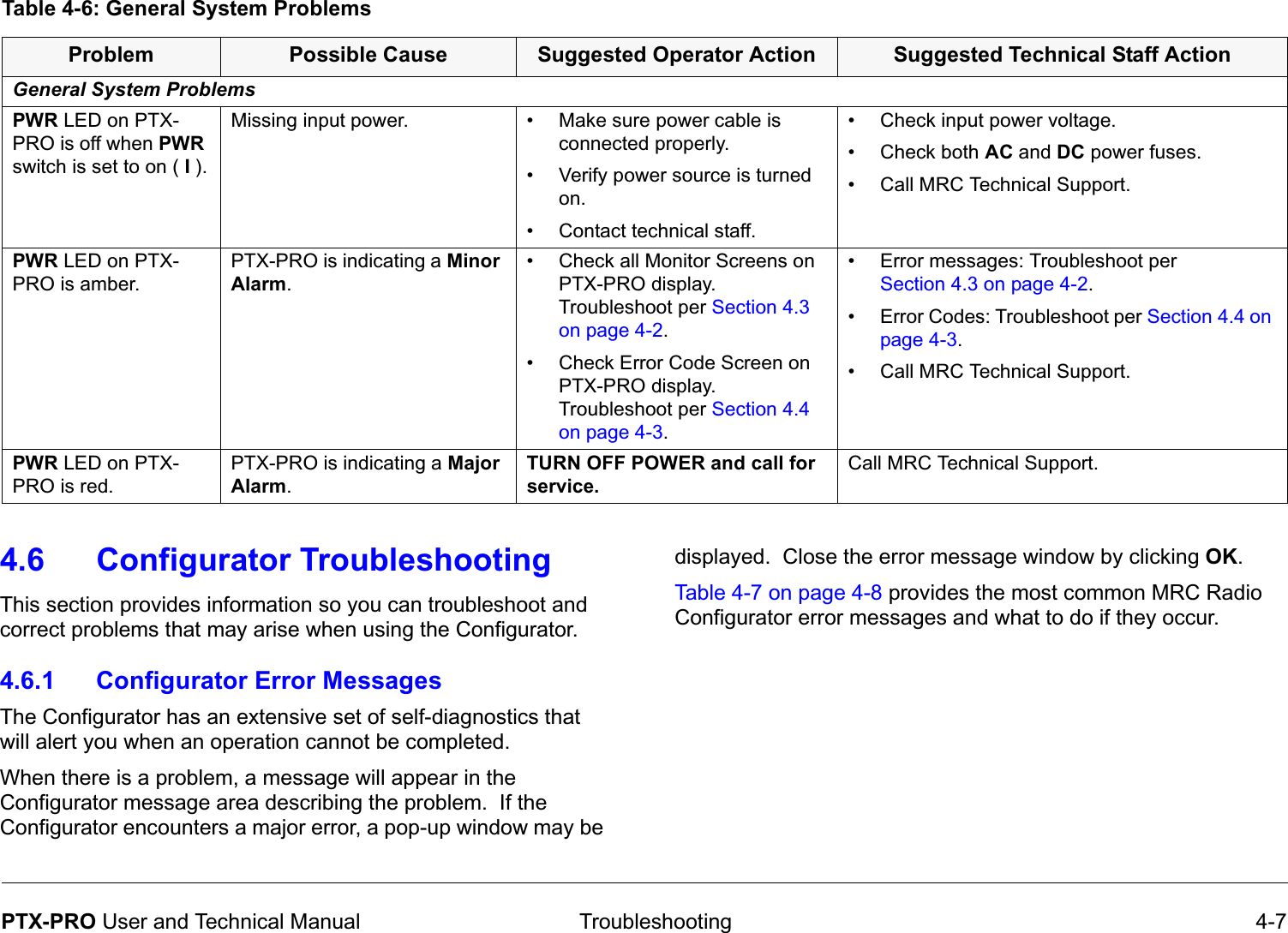
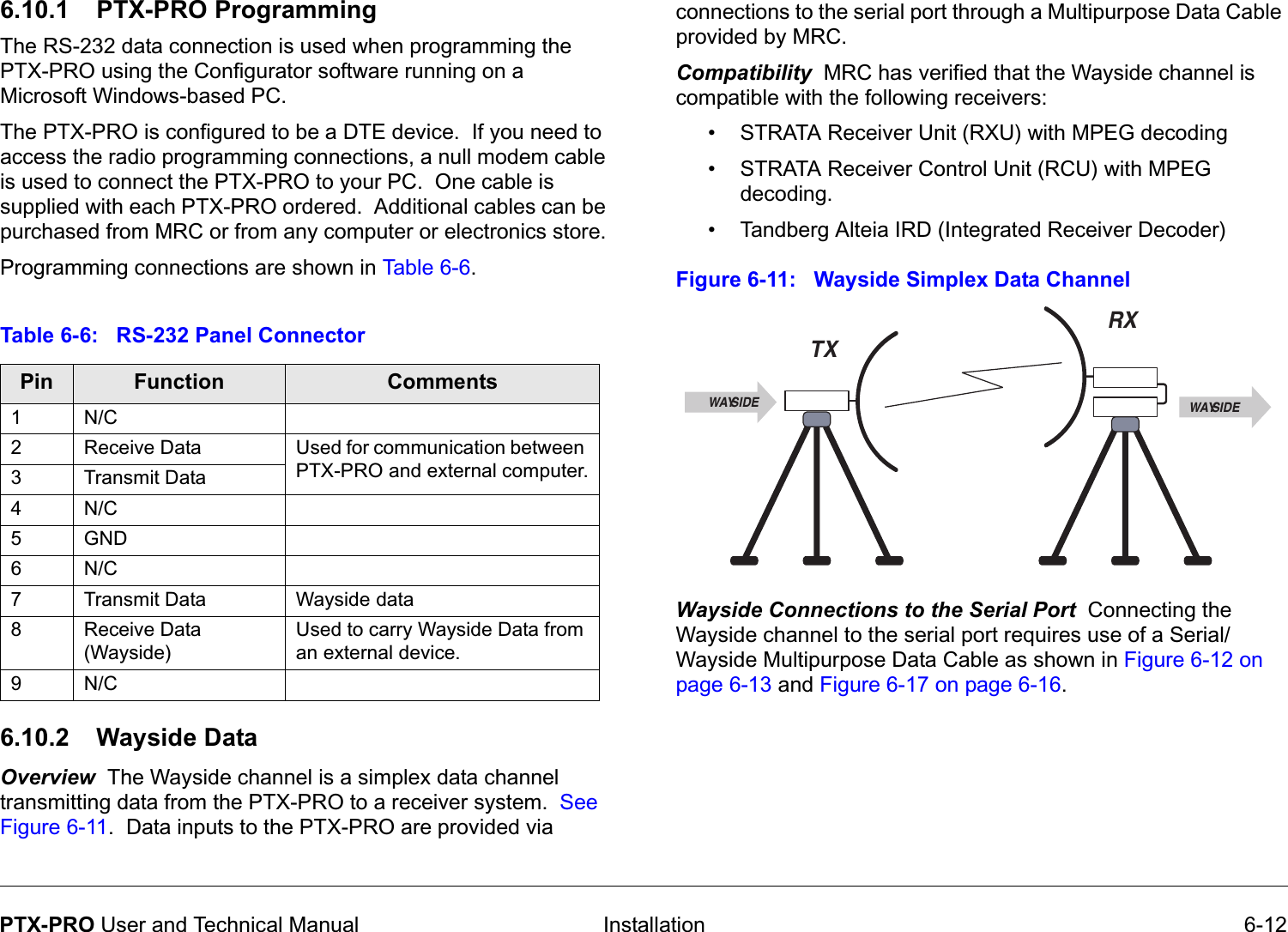
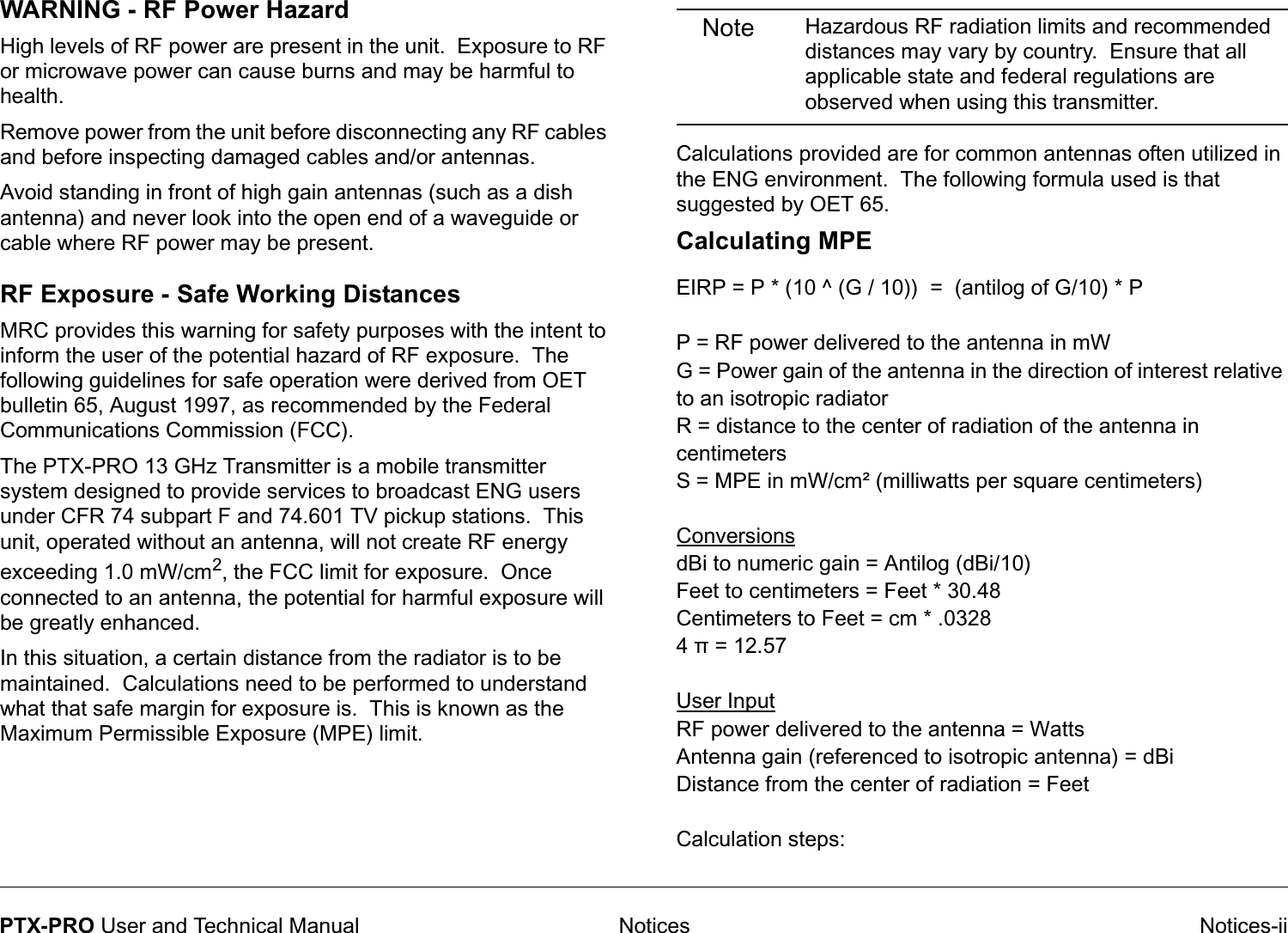
![Troubleshooting 4-8PTX-PRO User and Technical Manual Table 4-7: Configurator Error Messages Error Message Possible Cause Suggested ActionConnection failed on [COM port name]PTX-PRO system power is off.Turn PTX-PRO system power on.RS-232 cable is disconnected.Connect cable. Ensure connectors are fully seated on both ends.RS-232 cable is defective.Replace cable.Installed PTX-PRO hardware is defective.Contact MRC Technical Support.Querying [Setting] failed...Problem with RS-232 communication.Try again. If error still appears, turn off PTX-PRO system power, close the Configurator, then turn on PTX-PRO power and re-start Configurator.RS-232 cable is disconnected.Connect cable. Be sure connectors on both ends are fully seated.RS-232 cable is defective.Replace cable.Installed PTX-PRO hardware is defective.Contact MRC Technical Support.4.6.2 Configurator Operational ProblemsTable 4-8 provides the most common operational problems with the Configurator and what to do if they occur.Table 4-8: Configurator Operational ProblemsConfiguration File Corrupt ORUnable to Open Configuration FileUnable to read data stored in file chosen.Select a different configuration file.File damaged. Re-create configuration and save it with a different file name.Problem with PC or its disk drive.Contact your PC service provider.Problem Possible Cause Suggested ActionPC/Software ProblemsConfigurator won’t install on PC.Previous version of MRC Radio Configurator already installed.Uninstall previous version using the “Add/Remove Programs” function in Microsoft Windows Control Panel.PC does not meet System Requirements.See “PC Requirements” on page 6-17 .CD damaged. Contact MRC Technical Support.Problem with PC or its disk drive.Contact your PC service provider.Table 4-7: Configurator Error Messages (Continued)Error Message Possible Cause Suggested Action](https://usermanual.wiki/Microwave-Radio-Communications/PTX127T1CG/User-Guide-1143670-Page-38.png)

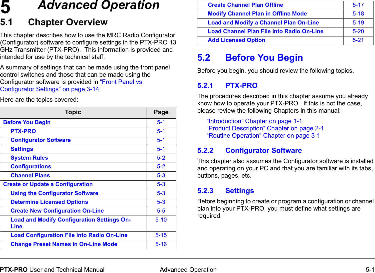
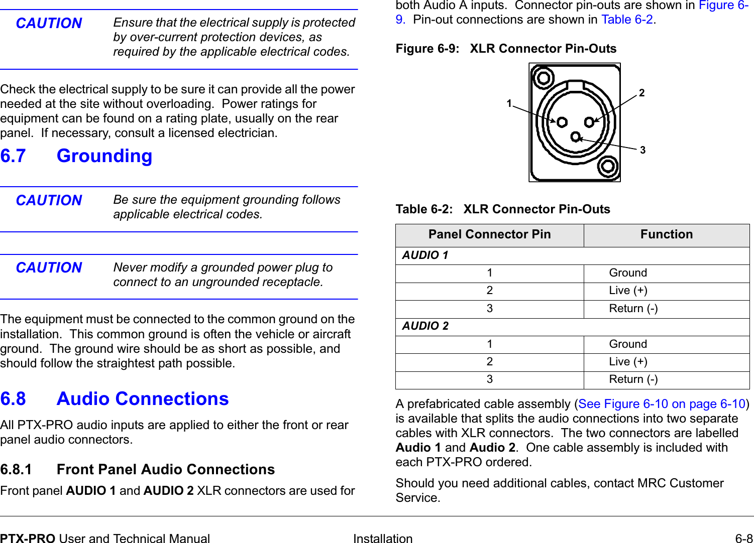
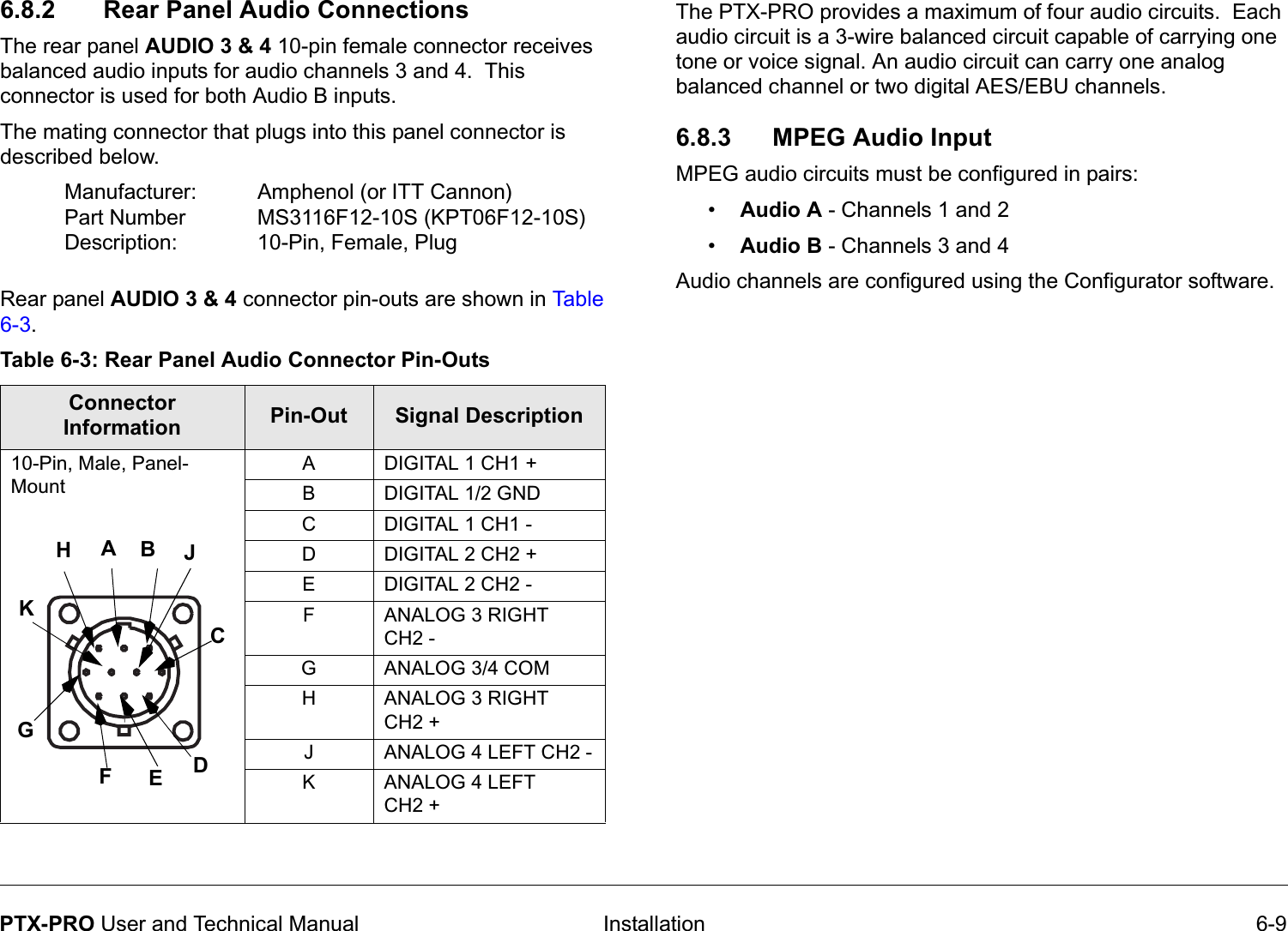
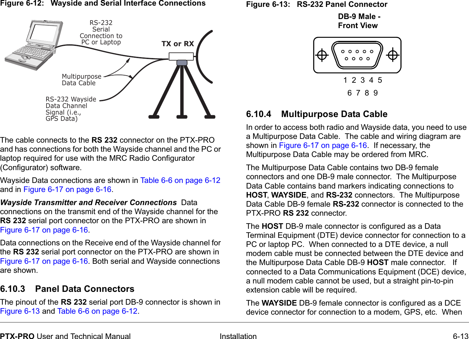
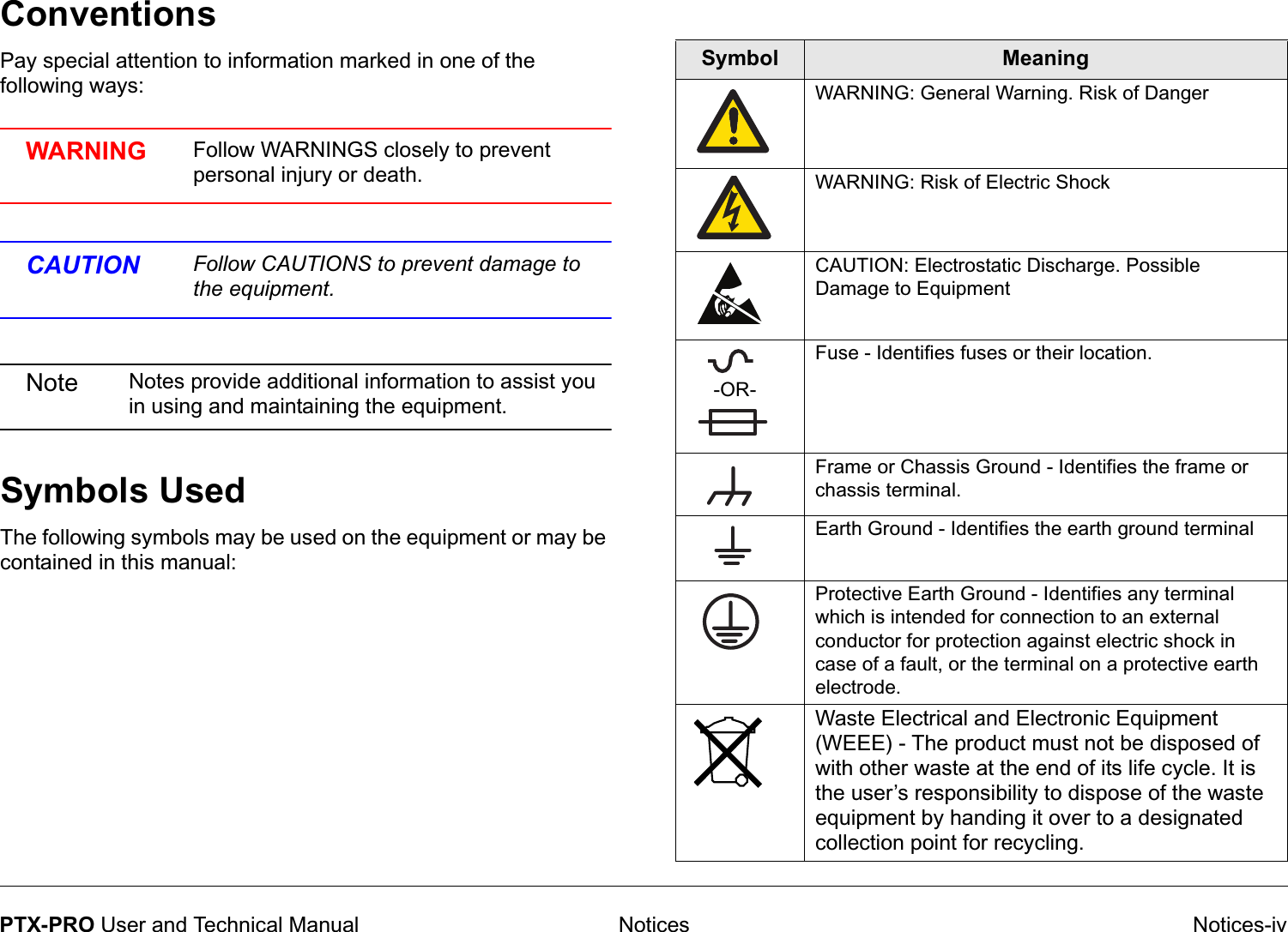
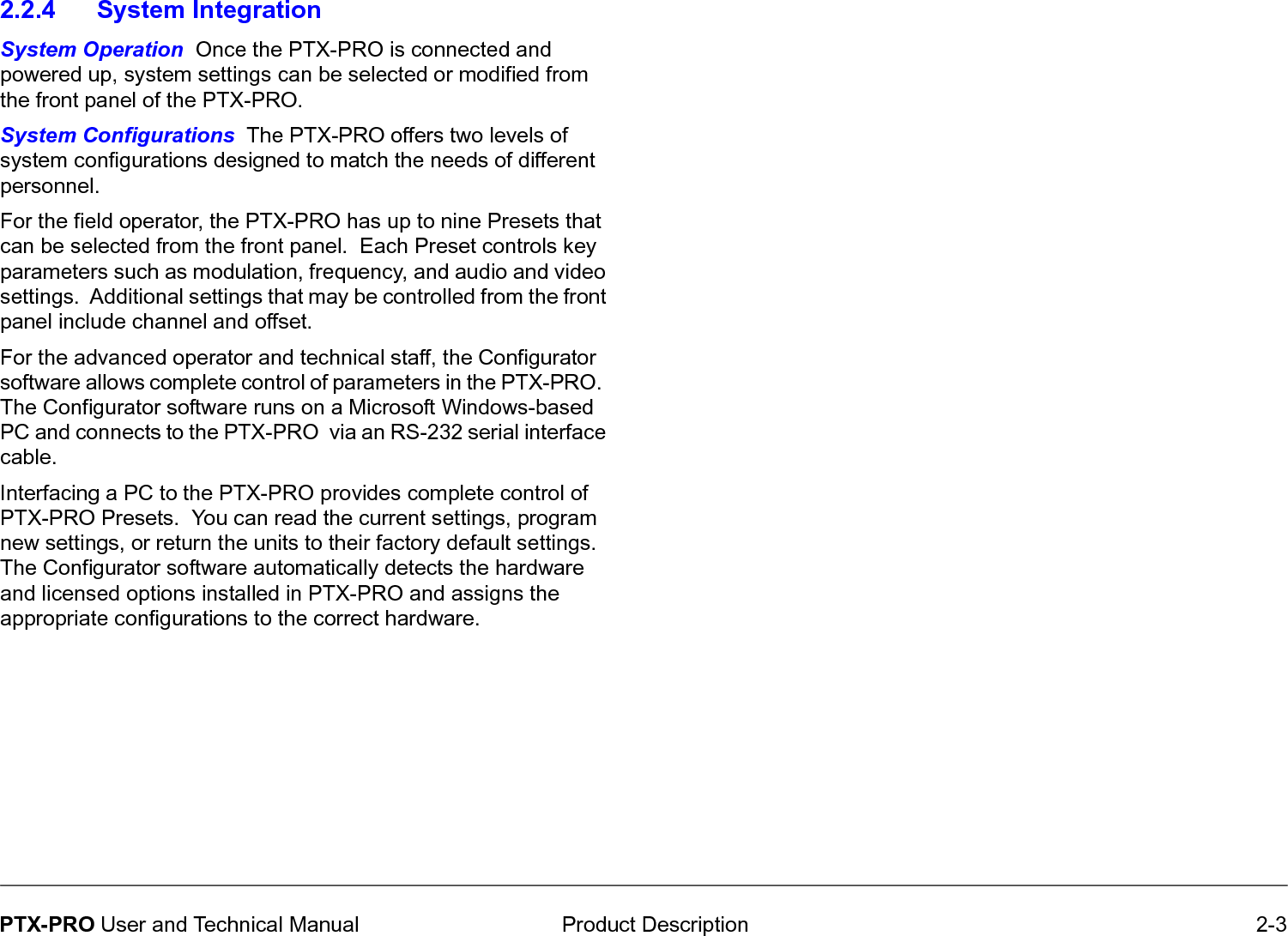
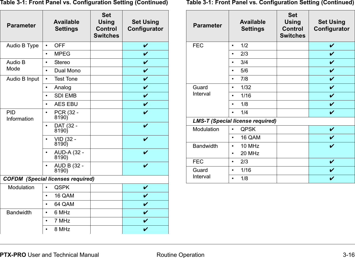
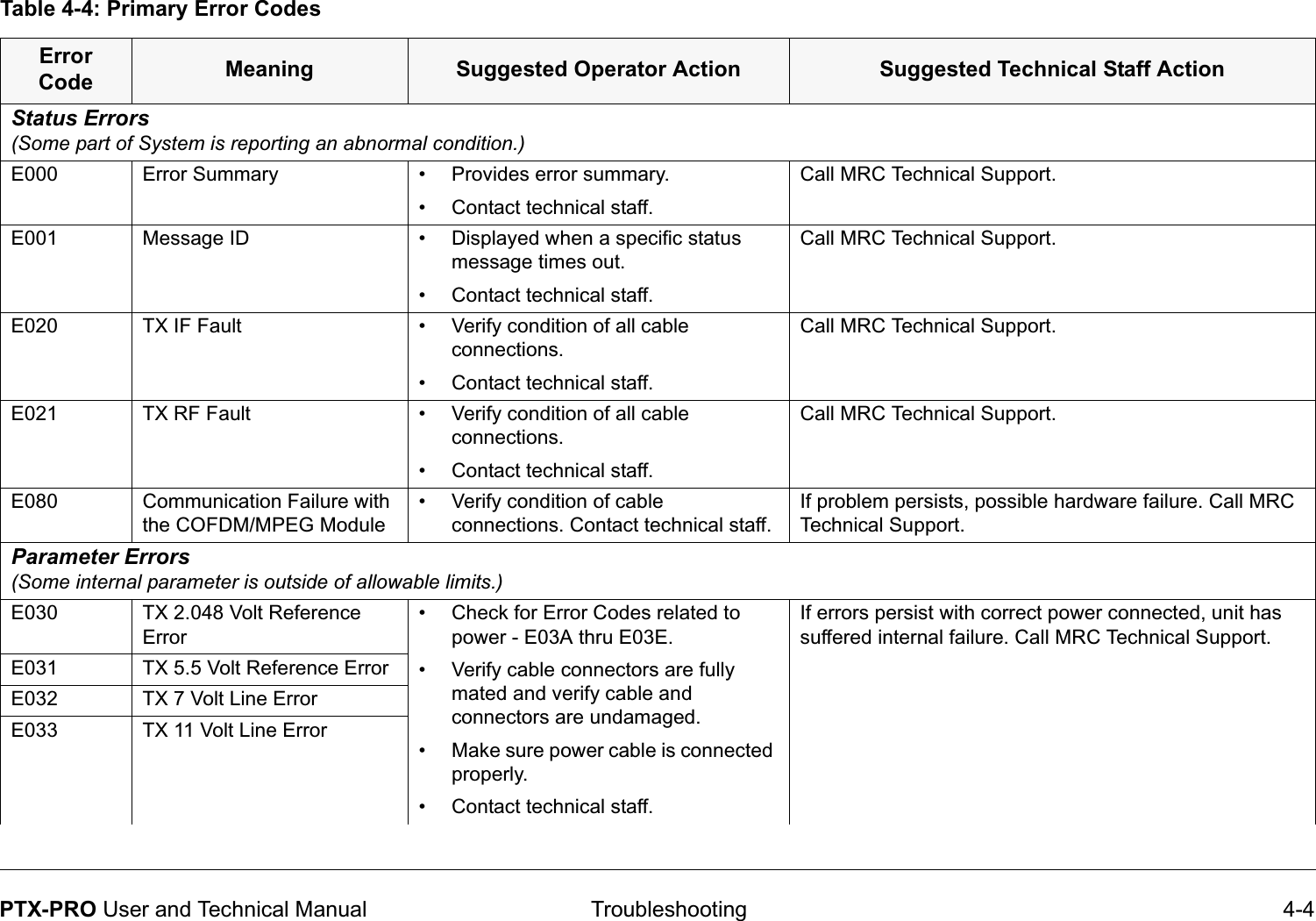
![Installation 6-10PTX-PRO User and Technical ManualFigure 6-10: Audio XLR Cable Assembly22.00"[55.88 cm]38.00"[96.52 cm]Face View6.8.4 AES/EBU Audio InputThe PTX-PRO will only provide digital audio when operating in digital mode.In digital mode, the PTX-PRO receives a digital signal and routes the data to the MPEG encoder and then to the COFDM modulator. The PTX-PRO audio switching circuitry connects the output of the MPEG encoder to the AUDIO connector. When configured for digital audio output (AES/EBU), the MPEG encoder provides two paired channels of digital data (+ and -), or four individual channels. All four circuits are balanced inputs, with each pair (+ and -) sharing one ground.In digital mode, the audio channels are referred to as Audio A and Audio B.6.8.5 Video ConnectionsThe PTX-PRO provides several video input and output options. Video connections are made to the BNC SIGNAL INPUT or SDI/ASI INPUT connectors located on the front panel of the PTX-](https://usermanual.wiki/Microwave-Radio-Communications/PTX127T1CG/User-Guide-1143670-Page-72.png)