Microwave Radio Communications PTX127T1CG 13GHz PTX-PRO User Manual User and Tech Manual
Microwave Radio Communications LLC 13GHz PTX-PRO User and Tech Manual
Manual
Manual Part No. 400590-1 Rev. B June 2009
PTX-PRO
13 GHz Transmitter
User and Technical Manual

Notices Notices-iPTX-PRO User and Technical Manual
Notices
About This Manual
Part number 400590-1
Revision B June 2009
PTX-PRO 13 GHz Transmitter (PTX-PRO)
Copyright
The information contained in this manual remains the property of
Microwave Radio Communications (MRC) and may not be used,
disclosed, or reproduced in any form whatsoever, without the
prior written consent of MRC.
MRC reserves the right to make changes to equipment and
specifications of the product described in this manual at any time
without notice and without obligation to notify any person of such
changes.
© 2009 Microwave Radio Communications
Microwave Radio Communications
101 Billerica Avenue - Bldg. 6
North Billerica, MA 01862-1256 USA
TEL: 800.490.5700
+1.978.671.5700
Printed in U.S.A.
The Microwave Radio Communications and Vislink trademarks
and other trademarks are registered trademarks in the United
States and/or other countries.
Microsoft®, Windows®, and Internet Explorer® are registered
trademarks of Microsoft Corporation in the United States and/or
other countries.
Proprietary Material
The information and design contained within this manual was
originated by and is the property of MRC. MRC reserves all
patent proprietary design, manufacturing, reproduction use, and
sales rights thereto, and to any articles disclosed therein, except
to the extent rights are expressly granted to others. The
foregoing does not apply to vendor proprietary parts.
MRC has made every effort to ensure the accuracy of the
material contained in this manual at the time of printing. As
specifications, equipment, and this manual are subject to change
without notice, MRC assumes no responsibility or liability
whatsoever for any errors or inaccuracies that may appear in this
manual or for any decisions based on its use. This manual is
supplied for information purposes only and should not be
construed as a commitment by MRC.
Quality Certification
Microwave Radio Communications is certified to ISO 9001:2000.
Changes or modifications not expressly approved by MRC could
void the user’s authority to operate the equipment.
General Safety Information
The following safety requirements, as well as local site
requirements and regulations, must be observed by personnel
operating and maintaining the equipment covered by this manual
to ensure awareness of potential hazards.

Notices Notices-iiPTX-PRO User and Technical Manual
WARNING - RF Power Hazard
High levels of RF power are present in the unit. Exposure to RF
or microwave power can cause burns and may be harmful to
health.
Remove power from the unit before disconnecting any RF cables
and before inspecting damaged cables and/or antennas.
Avoid standing in front of high gain antennas (such as a dish
antenna) and never look into the open end of a waveguide or
cable where RF power may be present.
RF Exposure - Safe Working Distances
MRC provides this warning for safety purposes with the intent to
inform the user of the potential hazard of RF exposure. The
following guidelines for safe operation were derived from OET
bulletin 65, August 1997, as recommended by the Federal
Communications Commission (FCC).
The PTX-PRO 13 GHz Transmitter is a mobile transmitter
system designed to provide services to broadcast ENG users
under CFR 74 subpart F and 74.601 TV pickup stations. This
unit, operated without an antenna, will not create RF energy
exceeding 1.0 mW/cm2, the FCC limit for exposure. Once
connected to an antenna, the potential for harmful exposure will
be greatly enhanced.
In this situation, a certain distance from the radiator is to be
maintained. Calculations need to be performed to understand
what that safe margin for exposure is. This is known as the
Maximum Permissible Exposure (MPE) limit.
Note Hazardous RF radiation limits and recommended
distances may vary by country. Ensure that all
applicable state and federal regulations are
observed when using this transmitter.
Calculations provided are for common antennas often utilized in
the ENG environment. The following formula used is that
suggested by OET 65.
Calculating MPE
EIRP = P * (10 ^ (G / 10)) = (antilog of G/10) * P
P = RF power delivered to the antenna in mW
G = Power gain of the antenna in the direction of interest relative
to an isotropic radiator
R = distance to the center of radiation of the antenna in
centimeters
S = MPE in mW/cm² (milliwatts per square centimeters)
Conversions
dBi to numeric gain = Antilog (dBi/10)
Feet to centimeters = Feet * 30.48
Centimeters to Feet = cm * .0328
4 π = 12.57
User Input
RF power delivered to the antenna = Watts
Antenna gain (referenced to isotropic antenna) = dBi
Distance from the center of radiation = Feet
Calculation steps:
Notices Notices-iiiPTX-PRO User and Technical Manual
1. [P] RF power input. Convert watts to milliwatts =
Watts * 1000
2. [G] Antenna gain dBi. Convert to numeric gain =
Antilog (dBi/10)
3. [EIRP] Multiply P * G
4. [R] Convert centimeters to feet = Centimeters * .0328
5. Square R
6. Multiply R² * 4π
7. [S] Divide (R² * 4π) into EIRP
S = Power Density in milliwatts per square centimeters.
Note: At frequencies above 1500 MHz, S must not be
greater than 1
Reference
FCC OET Bulletin 65, August 1997 - Evaluating
Compliance with FCC Guidelines for Human Exposure to
Radio Frequency Electromagnetic Fields
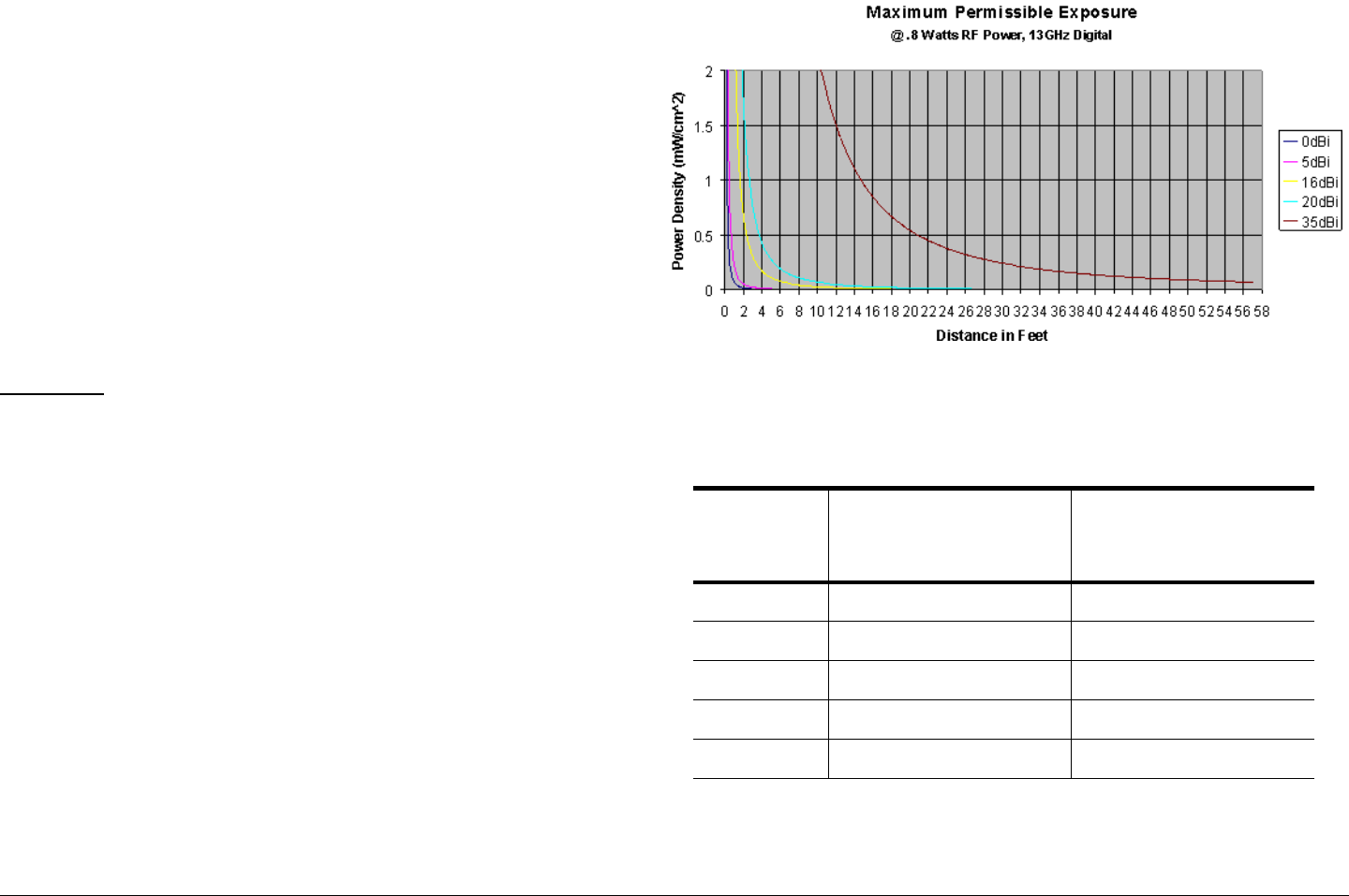
The example shown in Figure 1 is a typical graph for an
MRC PTX-PRO 13 GHz Transmitter and shows the
permissible exposure distance for various antennas.
Graphs and data will vary, based on the actual transmitter,
output power, frequency, and antenna utilized. The plot
provides the permissible output of the transmitter for digital
modulation
MRC, in accordance with the requirements set forth by the
FCC, provides this information as a guide to the user. It is
assumed that the users of this equipment are licensed and
qualified to operate the equipment per the guidelines and
recommendations contained within the product user guides
and in accordance with any FCC rules that may apply.
Figure 1: Digital Modulation
The following table reflects the graphic representations above.
Table 1:
Antenna
Gain (dBi)
Minimum
Distance from
Antenna (cm)
Minimum Distance
from Antenna (inch)
08 3.15
5 45 17.71
16 51 20.07
20 80 31.49
35 449 176.73
Notices Notices-ivPTX-PRO User and Technical Manual
Conventions
Pay special attention to information marked in one of the
following ways:
WARNING Follow WARNINGS closely to prevent
personal injury or death.
CAUTION Follow CAUTIONS to prevent damage to
the equipment.
Note Notes provide additional information to assist you
in using and maintaining the equipment.
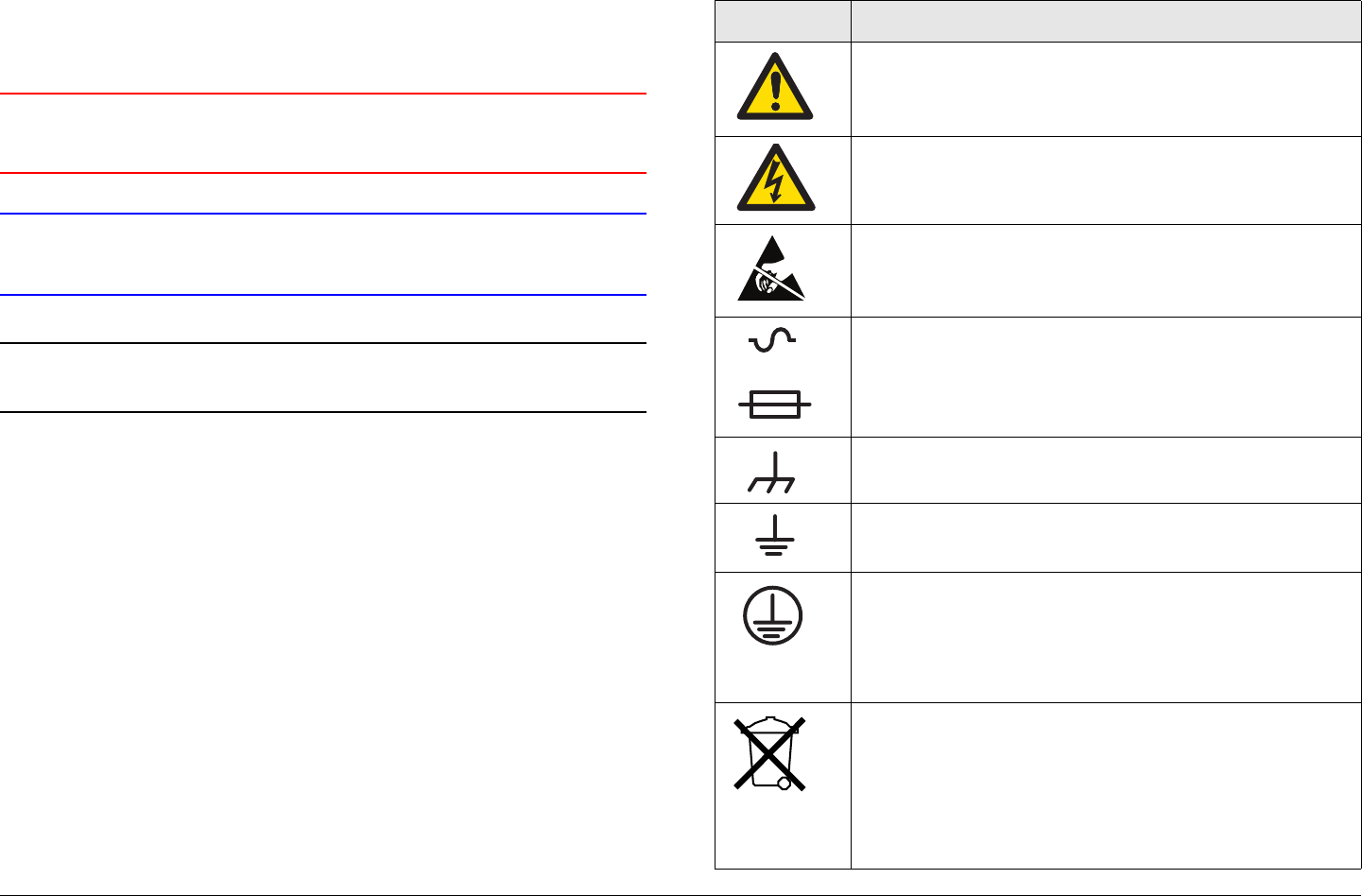
Symbols Used
The following symbols may be used on the equipment or may be
contained in this manual:
Symbol Meaning
WARNING: General Warning. Risk of Danger
WARNING: Risk of Electric Shock
CAUTION: Electrostatic Discharge. Possible
Damage to Equipment
-OR-
Fuse - Identifies fuses or their location.
Frame or Chassis Ground - Identifies the frame or
chassis terminal.
Earth Ground - Identifies the earth ground terminal
Protective Earth Ground - Identifies any terminal
which is intended for connection to an external
conductor for protection against electric shock in
case of a fault, or the terminal on a protective earth
electrode.
Waste Electrical and Electronic Equipment
(WEEE) - The product must not be disposed of
with other waste at the end of its life cycle. It is
the user’s responsibility to dispose of the waste
equipment by handing it over to a designated
collection point for recycling.

Contents Contents-1PTX-PRO User and Technical Manual
Contents
Introduction - - - - - - - - - - - - - - - - - - - - - - - - - - - 1-1
For Whom It’s Written - - - - - - - - - - - - - - - - - - - - - - - - 1-1
Related Documents - - - - - - - - - - - - - - - - - - - - - - - - - - 1-1
Ordering Documentation - - - - - - - - - - - - - - - - - - - - - - 1-1
Calling for Service - - - - - - - - - - - - - - - - - - - - - - - - - - - 1-1
Tell Us What You Think! - - - - - - - - - - - - - - - - - - - - - - 1-2
Product Description- - - - - - - - - - - - - - - - - - - - - 2-1
Description - - - - - - - - - - - - - - - - - - - - - - - - - - - - - - - - 2-1
Options - - - - - - - - - - - - - - - - - - - - - - - - - - - - - - - - 2-1
Power Options - - - - - - - - - - - - - - - - - - - - - - - - - - - 2-2
Mounting and Deployment Options - - - - - - - - - - - - 2-2
System Integration - - - - - - - - - - - - - - - - - - - - - - - - 2-3
Routine Operation - - - - - - - - - - - - - - - - - - - - - - 3-1
Overview of Controls, Indicators and Connectors - - - - - 3-1
Front Panel Controls, Indicators, and Connectors - - 3-2
Rear Panel Connectors and Fuses- - - - - - - - - - - - - 3-4
Preparing for Operation - - - - - - - - - - - - - - - - - - - - - - - 3-5
Portable Deployment - Typical - - - - - - - - - - - - - - - - 3-5
Powering the PTX-PRO Transmitter- - - - - - - - - - - - 3-5
Using the Display Screens - - - - - - - - - - - - - - - - - - - - - 3-6
PTX-PRO Monitoring Operations - - - - - - - - - - - - - - - - 3-6
Using the Monitor Screens in COFDM Mode - - - - - - 3-7
Using the Monitor Screens in ASI/SDI Input Mode - - 3-7
Using the Monitor Screens in Ext IF Input Mode - - - 3-7
Using the Monitor Screens in LMS-T Mode - - - - - - - 3-7
PTX-PRO Control Operations- - - - - - - - - - - - - - - - - - 3-12
Front Panel vs. Configurator Settings - - - - - - - - - - - - 3-14
Troubleshooting - - - - - - - - - - - - - - - - - - - - - - - 4-1
Power LED - - - - - - - - - - - - - - - - - - - - - - - - - - - - - - - - 4-1
Display Messages - - - - - - - - - - - - - - - - - - - - - - - - - - - 4-2
Error Codes - - - - - - - - - - - - - - - - - - - - - - - - - - - - - - - - 4-3
Error Status - - - - - - - - - - - - - - - - - - - - - - - - - - - - - 4-3
Primary Error Code - - - - - - - - - - - - - - - - - - - - - - - - 4-3
Operational Problems - - - - - - - - - - - - - - - - - - - - - - - - - 4-6
Configurator Troubleshooting - - - - - - - - - - - - - - - - - - - 4-7
Configurator Error Messages - - - - - - - - - - - - - - - - - 4-7
Configurator Operational Problems - - - - - - - - - - - - - 4-8
Advanced Operation - - - - - - - - - - - - - - - - - - - - 5-1
Before You Begin - - - - - - - - - - - - - - - - - - - - - - - - - - - - 5-1
PTX-PRO - - - - - - - - - - - - - - - - - - - - - - - - - - - - - - 5-1
Configurator Software - - - - - - - - - - - - - - - - - - - - - - 5-1
Settings - - - - - - - - - - - - - - - - - - - - - - - - - - - - - - - - 5-1
System Rules - - - - - - - - - - - - - - - - - - - - - - - - - - - - 5-2
Configurations- - - - - - - - - - - - - - - - - - - - - - - - - - - - 5-2
Channel Plans - - - - - - - - - - - - - - - - - - - - - - - - - - - 5-3
Create or Update a Configuration - - - - - - - - - - - - - - - - 5-3
Using the Configurator Software - - - - - - - - - - - - - - - 5-3
Determine Licensed Options - - - - - - - - - - - - - - - - - 5-3
Create New Configuration On-Line - - - - - - - - - - - - - 5-5
Load and Modify Configuration Settings On- Line - - 5-10
Load Configuration File into Radio On-Line - - - - - - 5-15
Change Preset Names in On-Line Mode - - - - - - - - 5-16
Create Channel Plan Offline - - - - - - - - - - - - - - - - - 5-17
Modify Channel Plan in Offline Mode- - - - - - - - - - - 5-18
Load and Modify a Channel Plan On-Line - - - - - - - 5-19
Load Channel Plan File into Radio On-Line - - - - - - 5-20
Add Licensed Option - - - - - - - - - - - - - - - - - - - - - - 5-21
Installation - - - - - - - - - - - - - - - - - - - - - - - - - - - 6-1
Unpacking - - - - - - - - - - - - - - - - - - - - - - - - - - - - - - - - 6-1
Initial Inspection - - - - - - - - - - - - - - - - - - - - - - - - - - - - - 6-1
Damage in Shipment - - - - - - - - - - - - - - - - - - - - - - - - - 6-1
Mounting and Cabling- - - - - - - - - - - - - - - - - - - - - - - - - 6-2
Portable Deployment - - - - - - - - - - - - - - - - - - - - - - - 6-2
Power Connections - - - - - - - - - - - - - - - - - - - - - - - - - - 6-5

Contents Contents-2PTX-PRO User and Technical Manual
Power Requirements - - - - - - - - - - - - - - - - - - - - - - 6-5
Power Supply and Distribution - - - - - - - - - - - - - - - - 6-5
Power Cable Assemblies - - - - - - - - - - - - - - - - - - - 6-6
Additional Powering Notes - - - - - - - - - - - - - - - - - - 6-7
Grounding - - - - - - - - - - - - - - - - - - - - - - - - - - - - - - - - 6-8
Audio Connections - - - - - - - - - - - - - - - - - - - - - - - - - - 6-8
Front Panel Audio Connections - - - - - - - - - - - - - - - 6-8
Rear Panel Audio Connections - - - - - - - - - - - - - - - 6-9
MPEG Audio Input - - - - - - - - - - - - - - - - - - - - - - - - 6-9
AES/EBU Audio Input - - - - - - - - - - - - - - - - - - - - - 6-10
Video Connections - - - - - - - - - - - - - - - - - - - - - - - 6-10
Signal Connections - - - - - - - - - - - - - - - - - - - - - - - - - 6-11
Data Connections - - - - - - - - - - - - - - - - - - - - - - - - - - 6-11
PTX-PRO Programming - - - - - - - - - - - - - - - - - - - 6-12
Wayside Data - - - - - - - - - - - - - - - - - - - - - - - - - - 6-12
Panel Data Connectors - - - - - - - - - - - - - - - - - - - - 6-13
Multipurpose Data Cable- - - - - - - - - - - - - - - - - - - 6-13
Networking - - - - - - - - - - - - - - - - - - - - - - - - - - - - 6-14
Powering Up - - - - - - - - - - - - - - - - - - - - - - - - - - - - - - 6-16
Checks before power-up - - - - - - - - - - - - - - - - - - - 6-16
Initial power-up - - - - - - - - - - - - - - - - - - - - - - - - - - 6-16
Configurator Software Installation - - - - - - - - - - - - - - - 6-17
PC Requirements - - - - - - - - - - - - - - - - - - - - - - - - 6-17
Installing Configurator Software - - - - - - - - - - - - - - 6-17
Product Modifications - - - - - - - - - - - - - - - - - - - - - - - - 6-20
Replacement Parts - - - - - - - - - - - - - - - - - - - - - 7-1
External Cables - - - - - - - - - - - - - - - - - - - - - - - - - - - - - 7-1
Mounting Hardware - - - - - - - - - - - - - - - - - - - - - - - - - - 7-1
Power Fuses - - - - - - - - - - - - - - - - - - - - - - - - - - - - - - - 7-2
Supported Repairs - - - - - - - - - - - - - - - - - - - - - - - - - - - 7-2
Theory of Operation - - - - - - - - - - - - - - - - - - - - 8-1
System Architecture - - - - - - - - - - - - - - - - - - - - - - - - - - 8-1
System Theory of Operation - - - - - - - - - - - - - - - - - - - - 8-2
MPEG/COFDM Encoder/Modulator Module- - - - - - - 8-2

1
Introduction 1-1PTX-PRO User and Technical Manual
Introduction
1.1 For Whom It’s Written
This manual is intended for use by qualified operators, installers,
and service personnel. Users of this manual should already be
familiar with the basic concepts of radio, video, and audio.
1.2 Related Documents
• Van Portable Systems User and Technical Manual
(part no. 400522-1)
• Glossary of Terms and Abbreviations (Part No. 400576-1)
1.3 Ordering Documentation
Any of the above manuals may be ordered by contacting MRC
Customer Service:
Business Hours: Monday - Friday
8:00 AM - 7:00 PM Eastern Time (US)
(0800 - 1900 hrs US ET)
Telephone: 800.490.5700 (Press 3)
+1.978.671.5700 (Press 3)
E-mail: customerservice@mrcbroadcast.com
When contacting Customer Service, please have the following
information available:
• Model number and serial number of the unit. This is
located on a label on the bottom of each unit.
• Approximate purchase date.
• Firmware version, which appears on the PTX-PRO
alphanumeric display at startup.
- OR -
• Firmware version(s) displayed on the Main page of the
MRC Radio Configurator (Configurator), when the
Configurator software is connected to the PTX-PRO.
1.4 Calling for Service
MRC Technical Support is available 24 hours a day, 7 days a
week. During regular business hours you can reach our expert
staff directly.
Business Hours: Monday - Friday
8:00 AM - 5:00PM Eastern Time (US)
(0800 - 1700 hrs US ET)
Telephone: 888.777.9221 (US and Canada)
+1.978.671.5929
E-mail: technicalsupport@mrcbroadcast.com
After regular business hours and on weekends and holidays, you
can also reach our expert staff as follows:
Telephone: 888.777.9221 (US and Canada)
+1.978.671.5929
Your call will be automatically forwarded to the on-call Technical
Support specialist.
When contacting Technical Support, please have the following
information available:

Introduction 1-2PTX-PRO User and Technical Manual
• Model number and serial number of the unit. This is
located on a label on the bottom of each unit.
• Approximate purchase date.
• Firmware version, which appears on the PTX-PRO
alphanumeric display at startup.
- OR -
• Firmware version(s) displayed on the Main page of the
MRC Radio Configurator (Configurator), when the
Configurator software is connected to the PTX-PRO.
1.5 Tell Us What You Think!
We’d appreciate any comments or suggestions you have about
this manual. The more feedback we get, the better the manuals
get!
If you’re viewing this manual electronically, it’s easy - just click on
the link below to send us an E-mail.
Or, you can E-mail our Technical Support team at:
technicalsupport@mrcbroadcast.com
Be sure to tell us what product you’re writing about, and which
document.
Feedback
2
Product Description 2-1PTX-PRO User and Technical Manual
Product Description
2.1 Chapter Overview
This chapter provides an overall description of the PTX-PRO
13 GHz Transmitter (PTX-PRO) components, options, and
capabilities.
Here are the topics covered:
2.2 Description
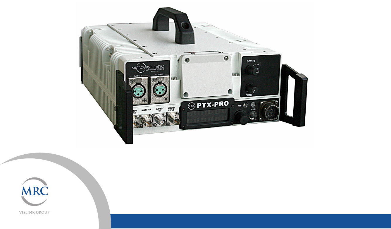
The PTX-PRO, as shown in Figure 2-1, is used for digital video
microwave communications and is designed to be a highly
reliable, flexible, and compact portable microwave transmitter for
either tripod or mobile applications.
The PTX-PRO is ideal for portable Electronic News Gathering
(ENG), Digital Video Broadcasting (DVB), mobile
communication, wireless airborne networks, and Outside
Broadcast (OB) systems.
The PTX-PRO architecture allows you the maximum flexibility in
configuration, siting, and operation. The PTX-PRO is a versatile
portable transmitter designed to accept a 70 MHz IF input signal
or composite video signal, audio signals, SD/HD SDI signals, or
ASI/SDI signals from external sources and to provide 13 GHz
Topic Page
Description 2-1
Options 2-1
Power Options 2-2
Mounting and Deployment Options 2-2
System Integration 2-3
microwave signal outputs for communications purposes.
Figure 2-1: PTX-PRO Transmitter - Typical
The PTX-PRO accepts either external 70 MHz, external IF,
composite video (CV), HD or SD SDI, or SDI/ASI input signals
and up-converts these signals to the 13 GHz RF band.
The RF frequency synthesizer circuit included in the IF/RF
module, in conjunction with the command and control power
supply module, provides the means to channelize RF video and
audio signals in the 13 GHz RF band, as applicable to the
configuration of the PTX-PRO.
Standard U.S. FCC band plans, as well as customer-created
channel plans, may be customized using the Configurator
software.
The PTX-PRO includes MPEG/CODFM modules and serves as
a stand-alone digital video microwave transmission system.
2.2.1 Options
All configurations are available with either NTSC or PAL system
modulation.
Product Description 2-2PTX-PRO User and Technical Manual
PTX-PRO options consist of the following:
Standard and High Definition Video All PTX-PRO
configurations are available with Standard Definition (SD) or SD
and optional High Definition (HD) video technologies.
Antenna Options The PTX-PRO is fully compatible with the
MRC family of transmit antennas, including the following:
• MRC MegaHorn Compact Horn
• MRC 2, 3, and 4 ft. Parabolic Antennas.
Contact your Sales Representative to explore the antenna
choices available.
2.2.2 Power Options
The architecture of the PTX-PRO allows a number of options for
the external power source. The PTX-PRO configurations
operate on the following external AC or DC power sources:
• 90 to 264 VAC, 50/60 Hz
• +11.0 to +36.0 VDC
A built-in universal AC and DC power supply provides full
flexibility in choosing power sources. For additional information,
refer to the “Installation” Chapter on page 6-1 .
Fuse ratings for the AC and DC power sources are shown in
Table 2-1.
Table 2-1: Fuse Ratings
Operating Voltage Fuse Rating
90 to 264 VAC, 50/60 Hz 2.0A, 250V AGC, Slow Blow
+11.0 to +36.0 VDC 15.0A, 250V, Slow Blow
CAUTION Avoid possible equipment damage. If you
are using a DC power source for your PTX-
PRO, do not exceed 36 volts DC input
power.
Refer to the “Installation” Chapter on page 6-1 for additional
information.
2.2.3 Mounting and Deployment Options
For more details on installation of the PTX-PRO in various
applications, see the “Installation” Chapter on page 6-1.
Portable Deployment In portable applications, the PTX-PRO is
typically mounted on an MRC Quick Release Mount for easy
attachment to an MRC tripod. The Quick Release Mount
connects to a Dovetail Adapter Plate machined into the MRC
tripod mount. Other mounting options are available.
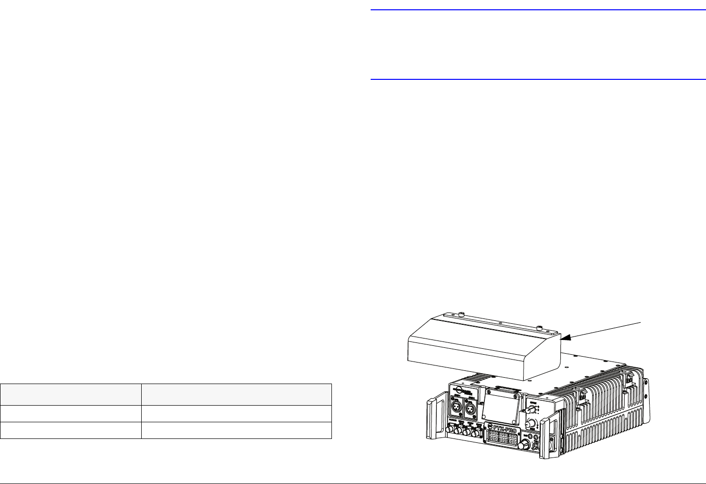
An optional Rain Shield, as shown in Figure 2-2, is available.
Figure 2-2: PTX-PRO with Optional Rain Shield
Optional
Rain
Shield

Product Description 2-3PTX-PRO User and Technical Manual
2.2.4 System Integration
System Operation Once the PTX-PRO is connected and
powered up, system settings can be selected or modified from
the front panel of the PTX-PRO.
System Configurations The PTX-PRO offers two levels of
system configurations designed to match the needs of different
personnel.
For the field operator, the PTX-PRO has up to nine Presets that
can be selected from the front panel. Each Preset controls key
parameters such as modulation, frequency, and audio and video
settings. Additional settings that may be controlled from the front
panel include channel and offset.
For the advanced operator and technical staff, the Configurator
software allows complete control of parameters in the PTX-PRO.
The Configurator software runs on a Microsoft Windows-based
PC and connects to the PTX-PRO via an RS-232 serial interface
cable.
Interfacing a PC to the PTX-PRO provides complete control of
PTX-PRO Presets. You can read the current settings, program
new settings, or return the units to their factory default settings.
The Configurator software automatically detects the hardware
and licensed options installed in PTX-PRO and assigns the
appropriate configurations to the correct hardware.

Product Description 2-4PTX-PRO User and Technical Manual

3
Routine Operation 3-1PTX-PRO User and Technical Manual
Routine Operation
3.1 Chapter Overview
This chapter provides basic information that will enable you to
operate your PTX-PRO 13 GHz Transmitter (PTX-PRO).
Here are the topics covered:
For a summary of settings that can be made with the PTX-PRO
front panel control switches and which settings are made using
the Configurator software, see Section 3.7 on page 3-14.
Information on settings made with the MRC Radio Configurator
(Configurator) software can be found in the “Advanced
Operation” Chapter on page 5-1.
Topic Page
Overview of Controls, Indicators and Connectors 3-1
Preparing for Operation 3-5
Portable Deployment - Typical 3-5
Powering the PTX-PRO Transmitter 3-5
Using the Display Screens 3-6
PTX-PRO Monitoring Operations 3-6
Using the Monitor Screens in COFDM Mode 3-7
Using the Monitor Screens in ASI/SDI Input Mode 3-7
Using the Monitor Screens in Ext IF Input Mode 3-7
Using the Monitor Screens in LMS-T Mode 3-7
PTX-PRO Control Operations 3-12
Front Panel vs. Configurator Settings 3-14
3.2 Overview of Controls, Indicators
and Connectors
This section describes the controls, indicators, and connectors
used on the PTX-PRO.
Controls, indicators, and connectors contained on the various
configurations of the PTX-PRO are identified and described
below. Topics covered are as follows:
Topic Page
Front Panel Controls, Indicators, and Connectors 3-2
PTX-PRO Front Panel Controls, Indicators, and
Connectors
3-2
Alphanumeric Display 3-2
OFFSET Switch 3-2
CHAN Switch 3-2
SIGNAL INPUT BNC Connector 3-2
MONITOR BNC Connector 3-2
PWR LED 3-2
SDI/HD/SD BNC Connector 3-3
SDI/ASI INPUT BNC Connector 3-3
Control Switch 3-3
XMIT LED 3-4
PWR Switch 3-4
AC/DC Power Connector 3-4
Rear Panel Connectors and Fuses 3-4
AUDIO 3 & 4/AES-EBU Connector 3-4
RF Output Type “N” Connector 3-4
AC Fuse 3-4
DC Fuse 3-5
Routine Operation 3-2PTX-PRO User and Technical Manual
3.2.1 Front Panel Controls, Indicators, and
Connectors
Each of these controls, indicators, and connectors are described
in more detail in the following paragraphs. Controls, indicators,
and connectors contained on the PTX-PRO front panel are
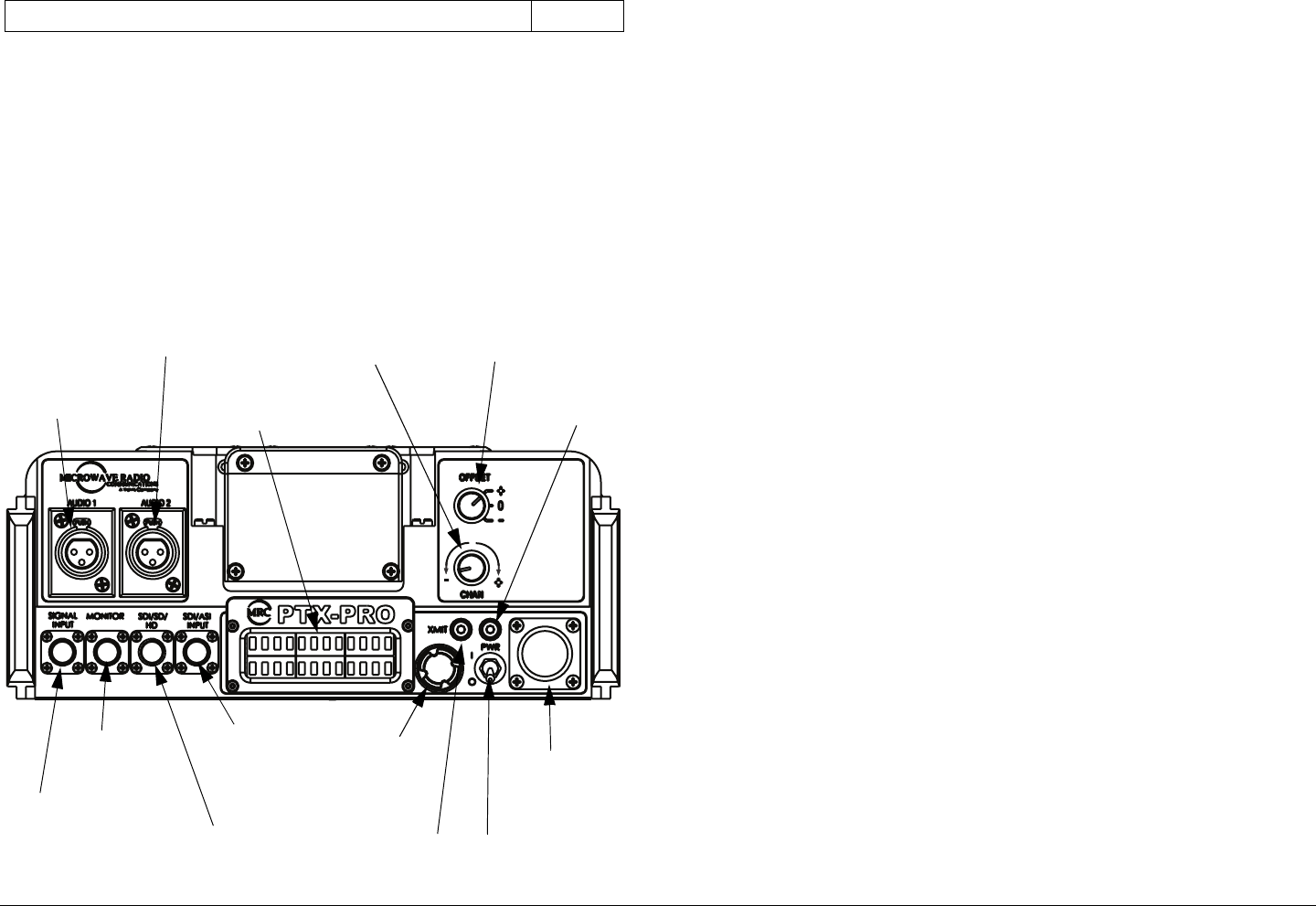
shown in Figure 3-1.
Figure 3-1: PTX-PRO Front Panel Controls, Indicators, and
Connectors
RS 232 DB-9 Connector 3-5
AUDIO 2
Connector
AUDIO 1
Connector
CHAN
Switch
OFFSET
Switch
Alphanumeric
Display
MONITOR
Connector
SIGNAL
INPUT
Connector
SDI/ASI
INPUT
Connector
AC/DC
Power
Connector
PWR
Switch
PWR
LED
XMIT
LED
Control
Switch
SDI/SD/HD
Connector
AUDIO 1 and AUDIO 2 XLR Connectors Each front panel
XLR AUDIO connector receives one channel of balanced audio
input.
Alphanumeric Display The PTX-PRO front panel contains a
two-line by 12-character alphanumeric display. The display
works in conjunction with the control switch to allow you to
monitor system status and to control system settings.
OFFSET Switch The front panel three-position OFFSET switch
provides selection of + (plus), 0 (center), or - (minus) channel
offset.
Note that OFFSET - (minus) cannot be selected for Channel 1
and OFFSET + (plus) cannot be selected for Channel 22.
CHAN Switch The front panel CHAN selector switch is used to
select the operating channel required. The CHAN selector
switch allows selection of 22 channels in the 13 GHz band.
Rotating the switch clockwise incrementally increases the
channel number and rotating the switch counterclockwise
decreases the channel number. The selected channel is
displayed on the Main screen of the alphanumeric display.
SIGNAL INPUT BNC Connector The front panel SIGNAL
INPUT 75 ohm BNC female connector provides the input
connection for 70 MHz IF or composite video to the unit.
MONITOR BNC Connector The front panel MONITOR 75 ohm
BNC female connector provides a 70 MHz output for external
signal monitoring.
PWR LED The front panel PWR (power) LED is a multi-color
status LED. PWR LED indications are as follows:
Routine Operation 3-3PTX-PRO User and Technical Manual
WARNING A Major Alarm may also indicate a potential
safety hazard.
Shut down the PTX-PRO and disconnect
power.
SDI/HD/SD BNC Connector The front panel SDI/HD/SD 75
ohm BNC female connector provides the HD/SD/SDI data
stream input to the unit.
SDI/ASI INPUT BNC Connector The front panel SDI/ASI
INPUT 75 ohm BNC female connector provides SDI or ASI
inputs to the unit.
Control Switch Routine PTX-PRO operating settings are
controlled by the front panel control switch. Turning the control
switch right (cw) displays monitor options, turning the control
switch left (ccw) displays command setting options, and
pressing the control switch in makes selections as described
below:
LED Color Meaning
----- Power is not on in the unit.
Green Power is on and no errors are detected.
Amber Minor Alarm - Power is on but some part of
the system reports an abnormal condition
that might impair performance.
Red Major Alarm - Power is on but there is a
failure or error that prevents normal
operation.
Turn the control switch to the right (cw) to view
Monitor options.
Monitor options are dependent upon the Preset
operating mode selected and provide current
status of the PTX-PRO. Status includes, but is
not limited to, the following:
• Frequency Setting
• Output Attenuation Level
• Frequency Band
• Operating Mode
• System Errors.
Turn the control switch to the left (ccw) to view
Command options.
The Command options allow control of the PTX-
PRO, including:
• Change Preset
• Change Video Mode to SD or HD
• Change SD or HD Video Mode Settings
• Change Color Bar Settings
• Setting Output Attenuation
Routine Operation 3-4PTX-PRO User and Technical Manual
XMIT LED When the PTX-PRO front panel control switch is
pressed for one second, the transmitter changes from the
standby mode to the transmit mode or from the transmit mode to
the standby mode. When the transmitter is in the transmit mode,
the front panel XMIT LED illuminates blue. When the transmitter
is in the standby mode, the XMIT LED is off.
PWR Switch The front panel PWR (power) switch controls
application of AC or DC power to the PTX-PRO.
AC/DC Power Connector The front panel AC/DC power
connector mounted on the front panel of the unit allows the PTX-
PRO to operate on external AC or DC power sources.
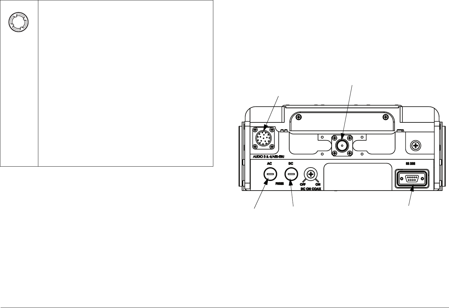
3.2.2 Rear Panel Connectors and Fuses
Controls, fuses, and connectors contained on the PTX-PRO rear
Pressing the control switch causes an action to
occur.
Command Options
• If the displayed setting is Chng Preset, Chng VI
Mode, Chng SD/HD VI, Chng Clr Bar, or Set TX
VVA, pressing the control switch causes the
displayed setting to blink.
Turning the control switch cw or ccw then displays
the other options for that setting.
When the desired option is displayed, pressing the
control switch selects that option.
Transmit
• Pressing the control switch for one second changes
the transmitter to the transmit mode from the
standby mode.
• Pressing the control switch for one second changes
the transmitter from the transmit mode to the
standby mode.
panel are shown in Figure 3-2.
AUDIO 3 & 4/AES-EBU Connector The rear panel 10-pin
female connector receives balanced audio inputs for audio
channels 3 and 4.
Figure 3-2: PTX-PRO Rear Panel Controls, Indicators, and
Connectors
RF Output Type “N” Connector The rear panel 50 ohm, type
“N”, female connector provides the RF output to the transmitting
antenna. The universal type “N” connector allows the PTX-PRO
to easily be used for emergency restoration of a Studio-
Transmitter Link (STL) or Inter-City Relay (ICR) link.
AC Fuse The rear panel AC fuse provides AC input power
protection for units used with AC power sources.
AUDIO 3 & 4/
AES-EBU
Connector
AC Fuse DC Fuse
RF Output
Connector
RS 232
Connector

Routine Operation 3-5PTX-PRO User and Technical Manual
DC Fuse The rear panel DC fuse provides DC input power
protection for units used with DC power sources.
RS 232 DB-9 Connector The RS 232 DB-9 connector provides
connections for factory test or to a Microsoft Windows-based PC
when using the Configurator software. The connector also
provides connections for Wayside data.
3.3 Preparing for Operation
Each installation or deployment will have its own specific tasks
according to the application and the installed hardware.
3.3.1 Portable Deployment - Typical
For portable applications where the PTX-PRO will be moved
from place to place and set up each time, the system will
typically be mounted on an MRC Quick Release Mount for easy
attachment to an MRC tripod. Other mounts are also available.
For additional information, refer to the “Installation” Chapter on
page 6-1.
3.3.2 Powering the PTX-PRO Transmitter
The procedures required to power up and power down the PTX-
PRO are contained in the following steps.
Power Up
1. Verify the power cable is properly connected to the
PTX-PRO front panel power connector.
2. Verify all front and rear panel cables and connectors
have been properly connected.
If you are unsure of the connections, refer to the
“Installation” Chapter on page 6-1.
Connect the power cable to the power source.
If you are unsure of the power requirements or the
connections, refer to the “Installation” Chapter on
page 6-1.
3. Verify the power source is turned on.
4. Set the front panel PWR switch to on ( I ).
5. The normal power-up sequence is as follows:
-The PWR LED above the PWR switch should
illuminate and should quickly change colors from red,
to green, to amber, to green, and should remain green.
- The alphanumeric display should light up and quickly
display a self-test screen, then the version of the
firmware, and finally the Main screen.
- Some typical screens are shown in Figure 3-3. Exact
screens displayed will vary.
- The PTX-PRO will typically power up using the last
settings in use when power was turned off.
- If the PTX-PRO does not power up normally, refer to
the “Troubleshooting” Chapter on page 4-1.
Figure 3-3: Typical PTX-PRO Power Up Screen
PTX-PRO
V X.X.X
Preset #1
0.00W C 3
Firmware
Version
Main Screen

Routine Operation 3-6PTX-PRO User and Technical Manual
Power Down
1. Set the PWR switch to off ( 0 ).
2. Set the power source power to off.
3.4 Using the Display Screens
As you use the PTX-PRO, you will interact extensively with the
screens displayed on the alphanumeric display. Following are
some points to make this easier.
Main Screen The Main screen is your starting point for
navigating through the Monitor and Control screens. The Main
screen provides the current values of the Preset selected and
the selected Preset output power level.
When the PTX-PRO completes its power-up sequence, the Main
screen will be displayed. A typical Main screen is shown in
Figure 3-4.
Figure 3-4: Main Screen - Typical
Accessing the Main Screen You can access the Main screen
at any time by scrolling to the end of the screens you are viewing
(either Monitor or Control). Your next click of the control switch
will bring up the Main screen.
Accessing the Monitor Screen You can access the Monitor
screen at any time by turning the control switch clockwise (cw).
Preset 3
. W
Currently
Selected
Preset
Output Power
Level
Accessing the Control Screen You can access the Control
screen at any time by turning the control switch counter-
clockwise (ccw).
Default to Main Screen If you do not turn or press the control
switch within a period of approximately 7 seconds, the display
will default to the Main screen.
If you turn the control switch within those 7 seconds, you will
continue scrolling within that set of screens (Monitor or Control).
3.5 PTX-PRO Monitoring Operations
The PTX-PRO Presets are set to five possible modes of
operation. These operating modes are established using the
Configurator software. Operating mode options displayed on the
Monitor screens are indicated below in bold fonts. Operating
mode options available via the Configurator software are as
follows:
• MPEG/COFDM IF Out (COFDM mode)
• COFDM Only - ASI In (ASI/SDI In mode)
• External 70MHz IF In (Ext IF Input mode)
• LMS-T (Terrestrial) (LMS-T mode)
Once the PTX-PRO is set up and powered up, you will be able to
check its configuration and monitor its operation. When
configuration settings are established for the individual Presets
using the Configurator software, the individual Preset operating
modes should be recorded for quick reference.
The following sections describe how to use the Monitor screens.
Here are the tasks described:

Routine Operation 3-7PTX-PRO User and Technical Manual
3.5.1 Using the Monitor Screens in COFDM Mode
When the PTX-PRO is operating in the COFDM mode, 70 MHz
COFDM IF output from the internal COFDM/MPEG board is
supplied to the RF output and MONITOR connectors. See
Figure 3-5 on page 3-8 for the COFDM Monitor Menu Map.
3.5.2 Using the Monitor Screens in ASI/SDI Input
Mode
When the PTX-PRO is operating in the ASI In mode, the internal
MPEG encoder is bypassed and an externally supplied ASI
stream is routed to the MONITOR and RF output connectors.
See Figure 3-6 on page 3-9 for the ASI In Menu Map.
3.5.3 Using the Monitor Screens in Ext IF Input
Mode
When the PTX-PRO is operating in the Ext. IF In mode, the 70
MHz IF input signal to the SIGNAL INPUT connector is routed
through the transmitter. See Figure 3-7 on page 3-10 for the Ext.
IF Monitor Map.
3.5.4 Using the Monitor Screens in LMS-T Mode
When the PTX-PRO is operating in the LMS-T mode, this mode
Topic Page
Using the Monitor Screens in COFDM Mode 3-7
Using the Monitor Screens in ASI/SDI Input Mode 3-7
Using the Monitor Screens in Ext IF Input Mode 3-7
Using the Monitor Screens in LMS-T Mode 3-7
utilizes a single carrier modulator and supplies a configurable
LMV-S signal to the transmitter RF output and MONITOR
connectors.
This mode is operational for QPSK and 16 QAM modulation
formats. See Figure 3-8 on page 3-11 for the LMS-T Monitor
Menu Map.
Routine Operation 3-8PTX-PRO User and Technical Manual
Figure 3-5: COFDM Monitor Menu Map - Typical
Mode
COFDM
QPSK 8MHz
ASI: Mb
Band
13 GHz
TX Attn
0.0dB
NTSC NoPdstl
Vid In 4:2:0
MPEG AudioA
AESEBU Streo
Error Page
COQPSK 8MHz
FE1/2 GI1/8
Preset
Displays power level
and Channel number.
Main Screen
This line will display Frequency
for Preset selected.
This line will display the same
information as the Main
Screen.
Displays will alternately
appear.
NOTE All Monitor Screens
revert to the Main Screen
after 7 seconds of
inactivity.
Monitor Menu Access:
TURN Control Switch
cw to view Monitor
options.
MPEG AudioB
AESEBU Streo
Video Delay
Normal
No Video
Vid In 4:2:0
Displays will alternately
appear if no video is present.
Routine Operation 3-9PTX-PRO User and Technical Manual
Figure 3-6: ASI/SDI Input Monitor Map - Typical
Mode
ASI/SDI In
QPSK 8MHz
ASI: Mb
IF CW OFF
Error Page
COQPSK 8MHz
FE1/2 GI1/8
Preset
Displays power level
and Channel number.
Main Screen
This line will display Frequency
for Preset selected.
This line will display the same
information as the Main
Screen.
Displays will alternately
appear.
NOTE All Monitor Screens
revert to the Main Screen
after 7 seconds of
inactivity.
Monitor Menu Access:
TURN Control Switch
cw to view Monitor
options.
TX Attn
0.0dB
Band
13 GHz
Routine Operation 3-10PTX-PRO User and Technical Manual
Figure 3-7: Ext IF Input Monitor Map - Typical
Mode
Ext IF Input
Error Page
Preset
Displays power level
and Channel number.
Main Screen
This line will display Frequency
for Preset selected.
This line will display the same
information as the Main
Screen.
NOTE All Monitor Screens
revert to the Main Screen
after 7 seconds of
inactivity.
Monitor Menu Access:
TURN Control Switch
cw to view Monitor
options.
TX Attn
0.0dB
Band
13 GHz
Routine Operation 3-11PTX-PRO User and Technical Manual
Figure 3-8: LMS-T Monitor Menu Map
Mode
LMS-T
QPSK 10MHz
ASI: Mb
Band
13 GHz
TX Attn
0.0dB
NTSC NoPdstl
Vid In 4:2:0
MPEG AudioA
AESEBU Streo
Error Page
QPSK 10MHz
FE2/3 GI1/8
Preset
Displays power level
and Channel number.
Main Screen
This line will display Frequency
for Preset selected.
This line will display the same
information as the Main
Screen.
Displays will alternately
appear.
NOTE All Monitor Screens
revert to the Main Screen
after 7 seconds of
inactivity.
Monitor Menu Access:
TURN Control Switch
cw to view Monitor
options.
MPEG AudioB
AESEBU Streo
Video Delay
Normal
No Video
Vid In 4:2:0
Displays will alternately
appear if no video is present.

Routine Operation 3-12PTX-PRO User and Technical Manual
3.6 PTX-PRO Control Operations
This section describes how to configure your PTX-PRO using
the front panel control switch. Turning the front panel control
switch counterclockwise (ccw) controls transmitter functions
including changing Presets, changing the video input (VI) mode,
changing SD or HD video inputs, changing color bar settings,
and setting RF attenuation levels.
See ”Front Panel vs. Configurator Settings” on page 3-14 for a
summary of settings that can be changed using the front panel
control switch and which are made using the Configurator
software. See Figure 3-9 on page 3-13 for the Control Menu
Map.
Routine Operation 3-13PTX-PRO User and Technical Manual
Figure 3-9: Control Menu Map
Chng Preset
Set TX Attn
Attn:
Preset
Main
Screen
NOTE
All Control Screens
revert to the Main
Screen after 7 seconds
of inactivity.
Control Menu Access:
TURN Control Switch
ccw and PRESS to
activate.
Displays power level
and Channel number.
Select Preset 1
thru Preset 9
Select 0 to -19
dB Attenuation
1) PRESS to activate
2) TURN to change
3) PRESS to select
1) PRESS to activate
2) TURN to change
3) PRESS to select
Returns to Main
Screen after
PRESS to select
SD Mode only
Chng SD VI
Select SD or HD
Select 525 Line SDI, NTSC,
or NTSC NoPdstl (NTSC) or
625 Line SDI, PAL In, PAL M In,
or PAL N In (PAL)
Chng HD VI
Select 1080i30,
1080i29, 1080i25,
720p60, 720p59, or
720p50
(SD Option) (HD Option)
1) PRESS to activate
2) TURN to change
3) PRESS to select
Chng Clr Bar Select Auto Gen,
Auto Standby, ON,
or OFF
1) PRESS to activate
2) TURN to change
3) PRESS to select
1) PRESS to activate
2) TURN to change
3) PRESS to select
1) PRESS to activate
2) TURN to change
3) PRESS to select
NOTE
The HD option may only be selected if
your PTX-PRO contains the licensed,
factory-enabled HD option. If the
licensed HD option is not present in
your radio, SD Mode Only will be
displayed in lieu of Chng VI Mode
and the video input mode cannot be
changed.
NOTE
The Chng VI Mode, Chng
SD/HD VI, and Chng Clr
Bar Control Screens are
present only if the Preset
operating mode is COFDM
or LMS-T.
Routine Operation 3-14PTX-PRO User and Technical Manual
3.7 Front Panel vs. Configurator
Settings
The design of the PTX-PRO and the Configurator software
makes commonly available settings accessible from the PTX-
PRO front panel switches and alphanumeric display and more
advanced settings accessible through the Configurator software.
A summary of settings that can be controlled by each method is
shown in Table 3-1.
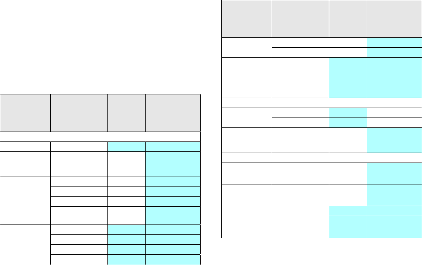
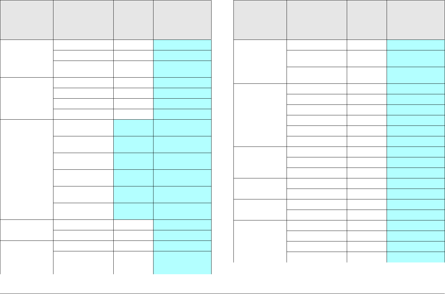
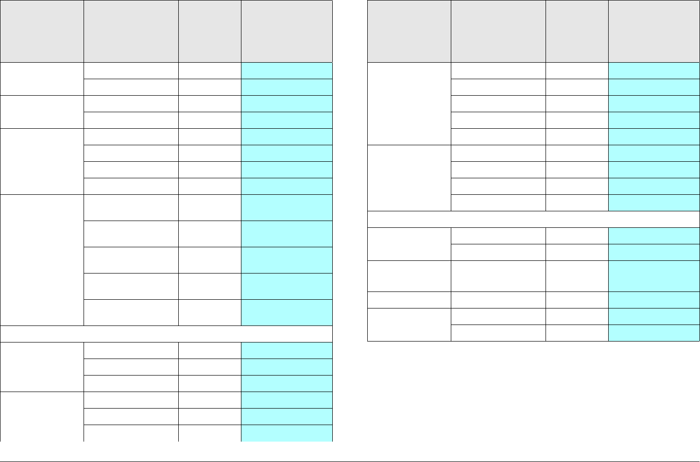
Table 3-1: Front Panel vs. Configuration Setting
Parameter Available
Settings
Set
Using
Control
Switches
Set Using
Configurator
Presets
Preset in use 1, 2,... 9 ✔ ✔
Preset text Any 12
alphanumeric
characters
✔
Operation
Mode
(Special
license
required for
LMS-T)
•COFDM ✔
• ASI In ✔
• Ext. IF In ✔
•LMS-T ✔
Color Bars • ON ✔ ✔
•OFF ✔ ✔
•Auto ✔ ✔
• Standby ✔ ✔
IF/CW Tone • ON ✔
•OFF ✔
Variable
Voltage
Attenuation
(TX VVA)
(Back Off)
• Variable (0 to
-19 dB in 1
dB steps)
✔ ✔
Channels
Channel &
Offset in use
• 1 thru 22 ✔
•+, 0, - ✔
Channel &
Offset
Frequencies
13 GHz band ✔
MPEG
Service
Name
• Any eight
alphanumeric
characters
✔
Network
Name
• Any eight
alphanumeric
characters
✔
Video Input
Mode
•SD ✔ ✔
• HD (Special
license
required)
✔ ✔
Table 3-1: Front Panel vs. Configuration Setting (Continued)
Parameter Available
Settings
Set
Using
Control
Switches
Set Using
Configurator
Routine Operation 3-15PTX-PRO User and Technical Manual
SD Video
Input Mode
(NTSC
Operation)
• SDI 525 In ✔
• NTSC In ✔
• NTSC No
Pedestal
✔
SD Video
Input Mode
(PAL
Operation)
• SDI 625 ✔
•PAL In ✔
• PAL M In ✔
• PAL N In ✔
HD Video
Input Mode
• 720p @ 50
Hz
✔ ✔
• 720p @
59.94 Hz
✔ ✔
• 720p @ 60
Hz
✔ ✔
• 1080i @ 25
Hz
✔ ✔
• 1080i @
29.97 Hz
✔ ✔
• 1080i @ 30
Hz
✔ ✔
Video Delay • Standard ✔
• Low ✔
Chroma
Format
•4:2:0 ✔
• 4:2:2 (Special
license
required)
✔
Table 3-1: Front Panel vs. Configuration Setting (Continued)
Parameter Available
Settings
Set
Using
Control
Switches
Set Using
Configurator
Wayside
State
•OFF ✔
•IRD
Compatible
✔
•STRATA
Compatible
✔
Wayside
Baud Rate
• 1200 ✔
• 2400 ✔
• 4800 ✔
• 9600 ✔
• 19200 ✔
• 38400 ✔
BISS
Encryption
•OFF ✔
•BISS-1 ✔
•BISS-E ✔
Audio A Type • OFF ✔
• MPEG ✔
Audio A
Mode
• Stereo ✔
• Dual Mono ✔
Audio A Input • Test Tone ✔
• Analog ✔
• SDI EMB ✔
• AES EBU ✔
Table 3-1: Front Panel vs. Configuration Setting (Continued)
Parameter Available
Settings
Set
Using
Control
Switches
Set Using
Configurator
Routine Operation 3-16PTX-PRO User and Technical Manual
Audio B Type • OFF ✔
• MPEG ✔
Audio B
Mode
•Stereo ✔
• Dual Mono ✔
Audio B Input • Test Tone ✔
• Analog ✔
• SDI EMB ✔
• AES EBU ✔
PID
Information
• PCR (32 -
8190)
✔
• DAT (32 -
8190)
✔
• VID (32 -
8190)
✔
• AUD-A (32 -
8190)
✔
• AUD B (32 -
8190)
✔
COFDM (Special licenses required)
Modulation • QSPK ✔
• 16 QAM ✔
• 64 QAM ✔
Bandwidth • 6 MHz ✔
•7 MHz ✔
•8 MHz ✔
Table 3-1: Front Panel vs. Configuration Setting (Continued)
Parameter Available
Settings
Set
Using
Control
Switches
Set Using
Configurator
FEC • 1/2 ✔
•2/3 ✔
•3/4 ✔
•5/6 ✔
•7/8 ✔
Guard
Interval
•1/32 ✔
•1/16 ✔
•1/8 ✔
•1/4 ✔
LMS-T (Special license required)
Modulation • QPSK ✔
• 16 QAM ✔
Bandwidth • 10 MHz
• 20 MHz
✔
FEC • 2/3 ✔
Guard
Interval
•1/16 ✔
•1/8 ✔
Table 3-1: Front Panel vs. Configuration Setting (Continued)
Parameter Available
Settings
Set
Using
Control
Switches
Set Using
Configurator
4
Troubleshooting 4-1PTX-PRO User and Technical Manual
Troubleshooting
4.1 Chapter Overview
This chapter describes how to troubleshoot your PTX-PRO 13
GHz Transmitter (PTX-PRO).
Here are the topics covered:
CAUTION To avoid possible equipment damage, turn
off DC on coax before connecting any test
equipment to the PTX-PRO RF output
connector.
4.2 Power LED
Above the PTX-PRO front panel PWR switch is a multi-color
PWR LED that provides unit status indications. The PWR LED
status indications are listed in Table 4-1.
Topic Page
Power LED 4-1
Display Messages 4-2
Error Codes 4-3
Operational Problems 4-6
Configurator Troubleshooting 4-7
Configurator Error Messages 4-7
Configurator Operational Problems 4-8
WARNING A Major Alarm may also indicate a
potential safety hazard.
Shut down the PTX-PRO and disconnect
power.
Table 4-1: Power LED Indications
LED
Color Meaning Suggested Action
----- Power is not on in the unit. Turn on power, as
required.
Green Power is on and no errors
are detected.
None.
Amber Minor Alarm - Power is on
but some part of the system
reports an abnormal
condition that requires
attention. Condition might
impair performance.
Check Monitor Screens
for error messages or
Error Codes.
Troubleshoot using
tables in this chapter.
Red Major Alarm - Power is on
but there is a serious failure
or error that will prevent
normal operation. The
internal processors are not
running.
Turn off unit and
disconnect power.
Call MRC Technical
Support.

Troubleshooting 4-2PTX-PRO User and Technical Manual
4.3 Display Messages
One of the ways the PTX-PRO will alert you to problems is by
error messages on the PTX-PRO front panel displays. These are
displayed on the Monitor screens.
See Table 4-2 for descriptions of the messages and what to do
when they appear.
Table 4-2: Display Messages
Message Meaning Suggested Operator Action Suggested Technical Staff Action
Not On Chnl Channel frequencies
defined in the Channel
Plan for that band are not
being recognized.
• Change the channel.
• Contact technical staff.
• Use Configurator software to check
settings. Check the Channel Plan to be
sure it is correct. Verify Channel Plan
matches the transmitter settings.
• If message persists even when
operating on a frequency that matches
the channel plan, unit may have
suffered internal failure. Call MRC
Technical Support.
No Video The PTX-PRO is unable to
lock onto video signal.
• Check for correct operation mode.
• Check cable connections to SIGNAL
INPUT and SDI/ASI INPUT connectors.
• Contact technical staff.
• Use Configurator software to check
settings.
• If message persists, unit may have
suffered internal failure. Call MRC
Technical Support.

Troubleshooting 4-3PTX-PRO User and Technical Manual
4.4 Error Codes
The PTX-PRO has a library of diagnostic error codes to help you
pinpoint any problems.
These error codes:
• Are displayed on the front panel display, on the Error
Code Screen.
•Cause the PWR status LED to glow amber, alerting you to
investigate the problem.
The Error Codes are formatted into 2 groups of characters, as
shown in Figure 4-1.
Figure 4-1: Error Code Format
E020 4
Primary Error Code
Identifies error
condition.
See ”Error Status”.
Error Status
Depends on error code.
See ”Primary Error Code”.
4.4.1 Error Status
The significance of the Error Status digit depends on what
Primary Error Code is being reported. See Table 4-3.
4.4.2 Primary Error Code
The first group of characters is the Primary Error Code. In most
cases this portion of the Error Code will uniquely identify the
problem.
See Table 4-4 on page 4-4 for descriptions of the error codes
and what to do when they appear.
Table 4-3: Error Status Digit
Status Digit Meaning
Status Error (Error Codes E020, E021, E080, and E0E0 thru
E0E4)
8 There is an error.
Parameter Error (Error Codes E030 thru E034, E03A thru
E03E, and E042 thru E049)
4 Value is too low.
8 Value is too high.

Troubleshooting 4-4PTX-PRO User and Technical Manual
Table 4-4: Primary Error Codes
Error
Code Meaning Suggested Operator Action Suggested Technical Staff Action
Status Errors
(Some part of System is reporting an abnormal condition.)
E000 Error Summary • Provides error summary.
• Contact technical staff.
Call MRC Technical Support.
E001 Message ID • Displayed when a specific status
message times out.
• Contact technical staff.
Call MRC Technical Support.
E020 TX IF Fault • Verify condition of all cable
connections.
• Contact technical staff.
Call MRC Technical Support.
E021 TX RF Fault • Verify condition of all cable
connections.
• Contact technical staff.
Call MRC Technical Support.
E080 Communication Failure with
the COFDM/MPEG Module
• Verify condition of cable
connections. Contact technical staff.
If problem persists, possible hardware failure. Call MRC
Technical Support.
Parameter Errors
(Some internal parameter is outside of allowable limits.)
E030 TX 2.048 Volt Reference
Error
• Check for Error Codes related to
power - E03A thru E03E.
• Verify cable connectors are fully
mated and verify cable and
connectors are undamaged.
• Make sure power cable is connected
properly.
• Contact technical staff.
If errors persist with correct power connected, unit has
suffered internal failure. Call MRC Technical Support.
E031 TX 5.5 Volt Reference Error
E032 TX 7 Volt Line Error
E033 TX 11 Volt Line Error

Troubleshooting 4-5PTX-PRO User and Technical Manual
E034 TX Temperature Error • Check PTX-PRO to be sure it is not
too close to sources of heat.
Relocate PTX-PRO, if possible.
• Verify PTX-PRO has room around it
for air circulation. Move objects
preventing air flow.
• Contact technical staff.
If errors persist with proper location and airflow and
correct power is connected, unit has suffered internal
failure. Call MRC Technical Support.
E038 50 Ohm Coax Current Error • Contact technical staff. Call MRC Technical Support.
E039 50 Ohm Coax Voltage Error
E03A 50 Ohm Coax Power Error
E03B TX Circular Connector
Current Error
• Verify all power cables are properly
connected and are not damaged.
• Verify correct input power is being
applied to the PTX-PRO.
• Contact technical staff.
If errors persist with correct power connected, unit has
suffered internal failure. Call MRC Technical Support.
E03C TX Circular Connector
Voltage Error
E03D TX Circular Connector
Power Error
E03E TX DC Bus Error • Contact technical staff. Call MRC Technical Support.
E03F TX Fan Fault • Contact technical staff. Call MRC Technical Support.
Table 4-4: Primary Error Codes (Continued)
Error
Code Meaning Suggested Operator Action Suggested Technical Staff Action

Troubleshooting 4-6PTX-PRO User and Technical Manual
4.5 Operational Problems
Information provided on the following pages will assist you in
troubleshooting problems that arise in the operation of your PTX-
PRO.
Table 4-5: Video Problems
Problem Possible Cause Suggested Operator Action Suggested Technical Staff
Action
Video Problems
No video. Problem with video source or
cabling
• Check video source and cabling.
• Contact technical staff.
• Check video source and
cabling.
• Call MRC Technical Support.
Transmitter and Receiver
compatibility problems
• Verify Transmitter and Receiver are both
operating in the same digital mode.
• Verify Transmitter and Receiver are both
operating on the same frequency. If
frequency offsets are used, verify offsets are
identical between Transmitter and Receiver.
• Contact technical staff.
• Call MRC Technical Support
Video source configuration
problem
• Verify PTX-PRO front panel settings match
video source inputs.
• Contact technical staff.
• Verify video inputs match
Configurator software settings.
• Call MRC Technical Support.
For video problems, See Table 4-5; for general system problems,
See Table 4-6 on page 4-7.

Troubleshooting 4-7PTX-PRO User and Technical Manual
Table 4-6: General System Problems
Problem Possible Cause Suggested Operator Action Suggested Technical Staff Action
General System Problems
PWR LED on PTX-
PRO is off when PWR
switch is set to on ( I ).
Missing input power. • Make sure power cable is
connected properly.
• Verify power source is turned
on.
• Contact technical staff.
• Check input power voltage.
• Check both AC and DC power fuses.
• Call MRC Technical Support.
PWR LED on PTX-
PRO is amber.
PTX-PRO is indicating a Minor
Alarm.
• Check all Monitor Screens on
PTX-PRO display.
Troubleshoot per Section 4.3
on page 4-2.
• Check Error Code Screen on
PTX-PRO display.
Troubleshoot per Section 4.4
on page 4-3.
• Error messages: Troubleshoot per
Section 4.3 on page 4-2.
• Error Codes: Troubleshoot per Section 4.4 on
page 4-3.
• Call MRC Technical Support.
PWR LED on PTX-
PRO is red.
PTX-PRO is indicating a Major
Alarm.
TURN OFF POWER and call for
service.
Call MRC Technical Support.
4.6 Configurator Troubleshooting
This section provides information so you can troubleshoot and
correct problems that may arise when using the Configurator.
4.6.1 Configurator Error Messages
The Configurator has an extensive set of self-diagnostics that
will alert you when an operation cannot be completed.
When there is a problem, a message will appear in the
Configurator message area describing the problem. If the
Configurator encounters a major error, a pop-up window may be
displayed. Close the error message window by clicking OK.
Table 4-7 on page 4-8 provides the most common MRC Radio
Configurator error messages and what to do if they occur.

Troubleshooting 4-8PTX-PRO User and Technical Manual
Table 4-7: Configurator Error Messages
Error Message Possible Cause Suggested
Action
Connection failed on
[COM port name]
PTX-PRO system
power is off.
Turn PTX-PRO
system power on.
RS-232 cable is
disconnected.
Connect cable.
Ensure connectors
are fully seated on
both ends.
RS-232 cable is
defective.
Replace cable.
Installed PTX-PRO
hardware is
defective.
Contact MRC
Technical Support.
Querying [Setting]
failed...
Problem with RS-
232 communication.
Try again. If error
still appears, turn off
PTX-PRO system
power, close the
Configurator, then
turn on PTX-PRO
power and re-start
Configurator.
RS-232 cable is
disconnected.
Connect cable. Be
sure connectors on
both ends are fully
seated.
RS-232 cable is
defective.
Replace cable.
Installed PTX-PRO
hardware is
defective.
Contact MRC
Technical Support.
4.6.2 Configurator Operational Problems
Table 4-8 provides the most common operational problems with
the Configurator and what to do if they occur.
Table 4-8: Configurator Operational Problems
Configuration File
Corrupt
OR
Unable to Open
Configuration File
Unable to read data
stored in file chosen.
Select a different
configuration file.
File damaged. Re-create
configuration and
save it with a
different file name.
Problem with PC or
its disk drive.
Contact your PC
service provider.
Problem Possible Cause Suggested Action
PC/Software Problems
Configurator
won’t install on
PC.
Previous version of
MRC Radio
Configurator already
installed.
Uninstall previous
version using the “Add/
Remove Programs”
function in Microsoft
Windows Control Panel.
PC does not meet
System
Requirements.
See “PC Requirements”
on page 6-17 .
CD damaged. Contact MRC Technical
Support.
Problem with PC or
its disk drive.
Contact your PC service
provider.
Table 4-7: Configurator Error Messages (Continued)
Error Message Possible Cause Suggested
Action

Troubleshooting 4-9PTX-PRO User and Technical Manual
Configurator
crashes when
trying to run.
AND / OR
Get “Runtime
Error” message.
Program files
damaged.
Use the “Add/Remove
Programs” function in
Microsoft Windows
Control Panel to
uninstall the
Configurator, then
reinstall it.
Problem with PC or
its disk drive.
Contact your PC service
provider.
Problem Possible Cause Suggested Action

Troubleshooting 4-10PTX-PRO User and Technical Manual
5
Advanced Operation 5-1PTX-PRO User and Technical Manual
Advanced Operation
5.1 Chapter Overview
This chapter describes how to use the MRC Radio Configurator
(Configurator) software to configure settings in the PTX-PRO 13
GHz Transmitter (PTX-PRO). This information is provided and
intended for use by the technical staff.
A summary of settings that can be made using the front panel
control switches and those that can be made using the
Configurator software is provided in “Front Panel vs.
Configurator Settings” on page 3-14.
Here are the topics covered:
Topic Page
Before You Begin 5-1
PTX-PRO 5-1
Configurator Software 5-1
Settings 5-1
System Rules 5-2
Configurations 5-2
Channel Plans 5-3
Create or Update a Configuration 5-3
Using the Configurator Software 5-3
Determine Licensed Options 5-3
Create New Configuration On-Line 5-5
Load and Modify Configuration Settings On-
Line
5-10
Load Configuration File into Radio On-Line 5-15
Change Preset Names in On-Line Mode 5-16
5.2 Before You Begin
Before you begin, you should review the following topics.
5.2.1 PTX-PRO
The procedures described in this chapter assume you already
know how to operate your PTX-PRO. If this is not the case,
please review the following Chapters in this manual:
“Introduction” Chapter on page 1-1
“Product Description” Chapter on page 2-1
“Routine Operation” Chapter on page 3-1
5.2.2 Configurator Software
This chapter also assumes the Configurator software is installed
and operating on your PC and that you are familiar with its tabs,
buttons, pages, etc.
5.2.3 Settings
Before beginning to create or program a configuration or channel
plan into your PTX-PRO, you must define what settings are
required.
Create Channel Plan Offline 5-17
Modify Channel Plan in Offline Mode 5-18
Load and Modify a Channel Plan On-Line 5-19
Load Channel Plan File into Radio On-Line 5-20
Add Licensed Option 5-21

Advanced Operation 5-2PTX-PRO User and Technical Manual
5.2.4 System Rules
CAUTION Do not make any configuration changes to
your PTX-PRO while the PTX-PRO is
connected to a radio system that is actively
transmitting.
Attempts to program configuration changes
into a PTX-PRO when the radio system is
actively transmitting will interrupt broadcast
operations.
When configuring your PTX-PRO on-line (connected to a PC), the
following system rules must be followed.
• When the PTX-PRO is properly connected to your PC and
the system is powered up, the Configurator software will
automatically detect your PTX-PRO, your hardware
configuration, and the licensed options contained in your
PTX-PRO.
• The PTX-PRO must be powered up prior to initializing the
Configurator software.
• The configuration settings can be saved to the PTX-PRO or
can be saved to a file and can be recalled at a later date.
• Configuration settings may be loaded into the Configurator
from your PTX-PRO, may be modified, and may be loaded
into your PTX-PRO and/or saved to a file in the on-line
mode.
• The PTX-PRO must not be placed in the transmit mode
when utilizing the Configurator software.
• Channel plans may be created in the on-line mode or in the
offline mode. Channel plans created in the offline mode
can be saved to a file on your PC and can be recalled at a
later date.
• Channel plans may be loaded into the Configurator from
your PTX-PRO, may be modified, and may be loaded into
your PTX-PRO and/or saved to a file in the on-line mode.
• PTX-PRO configurations and channel plans may be
created or modified from a file on your PC in the on-line
mode.
• When selecting options in the on-line mode, if the option
is a licensed option that is not contained in your radio, the
option may not be displayed, e.g., if you do not have the
LMS-T licensed option in your radio, the LMS-T tab will
not be present on the Configurator.
• In certain instances, licensed options may be displayed
on a Configurator page, but if your radio does not contain
the licensed option, the option will be inactive, you cannot
select the option, and you cannot load the option into your
radio.
The procedures required to create or update configurations and/
or channel plans are provided in the following sections.
5.2.5 Configurations
New configurations can created from scratch, updated from
existing files on your PC, or may be loaded in from a PTX-PRO
and modified. Once a configuration is created or modified and
saved, you can load the configuration into your PTX-PRO. The
steps required to load configuration changes are provided in the
applicable procedures.
Once a configuration is created or modified, it should be saved to
a file on your PC. The steps required to save configuration
settings are provided in the applicable procedures provided in
this Chapter.

Advanced Operation 5-3PTX-PRO User and Technical Manual
5.2.6 Channel Plans
New channel plans can be created from scratch, updated from
existing files on your PC, or may be loaded in from a PTX-PRO
and modified. Once a channel plan is created or modified and
saved, you can load the channel plan into your PTX-PRO. The
steps required to load channel plan changes are provided in the
applicable procedures provided in this Chapter.
Once a channel plan is created or modified, it should be saved to
a file on your PC. The steps required to save channel plan
settings are provided in the applicable procedures.
5.3 Create or Update a Configuration
There are various ways to create or modify a configuration on-
line with the PTX-PRO connected to a PC via an RS-232 link.
• Create a configuration on-line.
• Load in an existing configuration from a file and modify it
on-line.
•Load in a configuration from the PTX-PRO and modify it.
• Load and modify individual configuration pages.
• Once a configuration is created and saved to a file on
your PC, the configuration file can be loaded into the PTX-
PRO.
Each of these methods is explained in detailed steps in the
following sections.
5.3.1 Using the Configurator Software
The MRC Radio Configurator software has an easy-to-use
Graphical User Interface (GUI) to access Preset configuration
settings and channel plan settings. The Configurator software is
accessed through the MRC Radio Configurator icon displayed
on your PC desktop.
The settings are grouped into pages according to function. The
pages are accessed using tabs. Pages also contain option
buttons, pull-down menus, text boxes, radio buttons, and check
boxes to select or activate different functions and options.
Procedures contained in this Chapter utilize easy-to-use
flowcharts to navigate through the various procedures. The
procedures allow use of the Configurator in the on-line mode
with the Configurator software connected to the PTX-PRO via an
RS-232 interface.
5.3.2 Determine Licensed Options
Prior to preparing or modifying any PTX-PRO configuration
settings in the offline mode, you must determine what licensed
options are contained in your PTX-PRO.
If you have not previously recorded your PTX-PRO licensed
options, you must perform this procedure.
In order to determine the licensed options contained in your
PTX-PRO, you must connect your PTX-PRO to the Configurator
software via an RS-232 link to your PC. When your PTX-PRO is
powered up and is connected to the Configurator in the on-line
mode, the Configurator software automatically detects the
licensed options contained in your PTX-PRO.
After determining what licensed options are contained in your
PTX-PRO, you must record the options. You can then
disconnect from the Configurator software and can prepare
configuration settings in the offline mode without having your
PTX-PRO connected to your PC and the Configurator software.
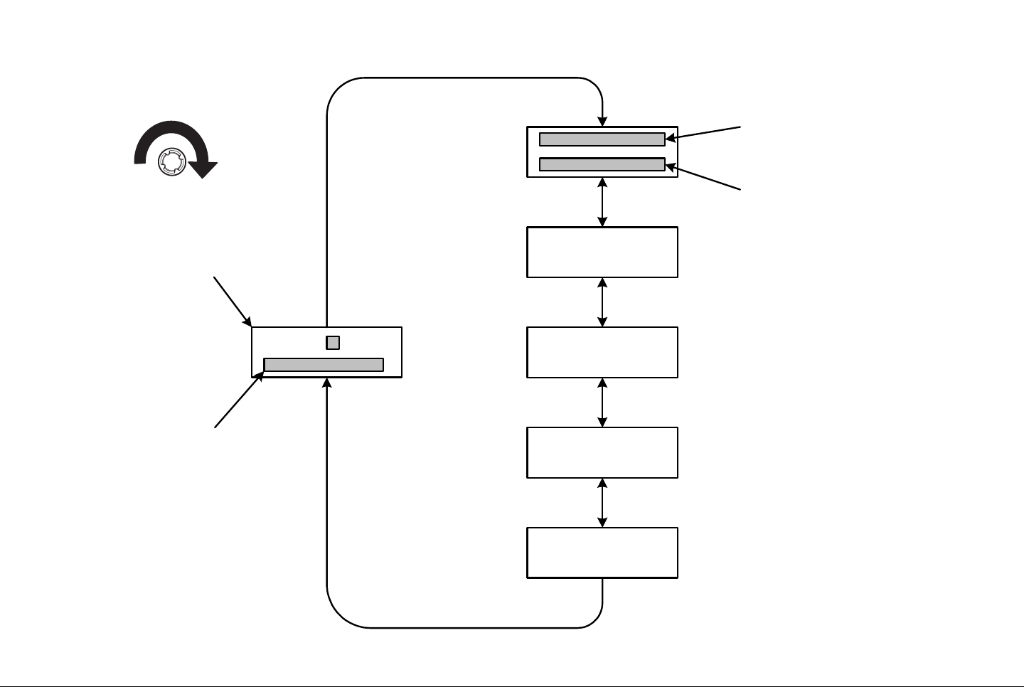
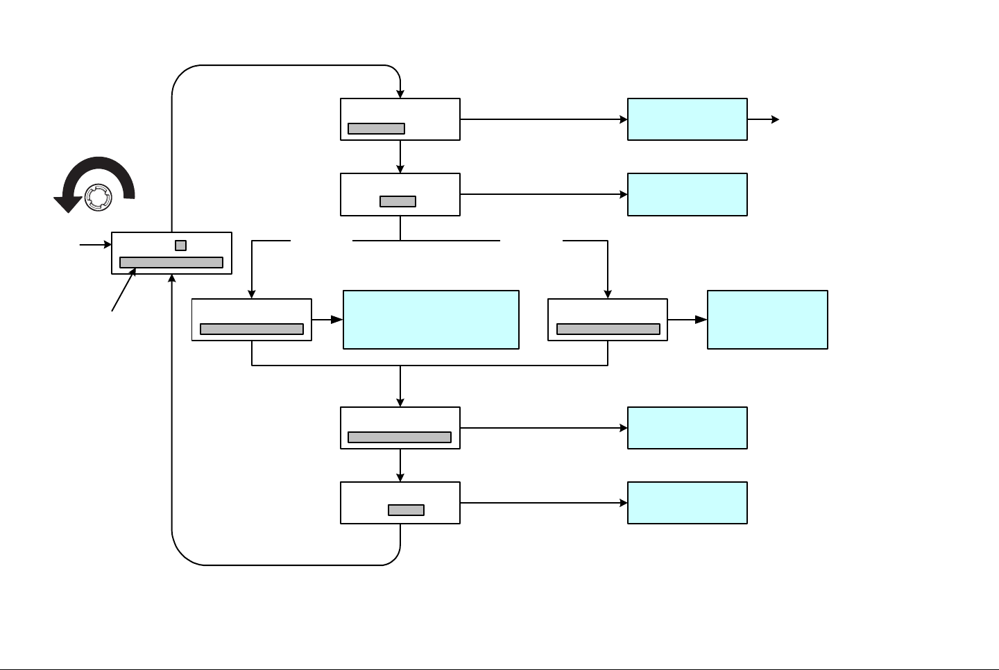
The flowchart required to determine the licensed options
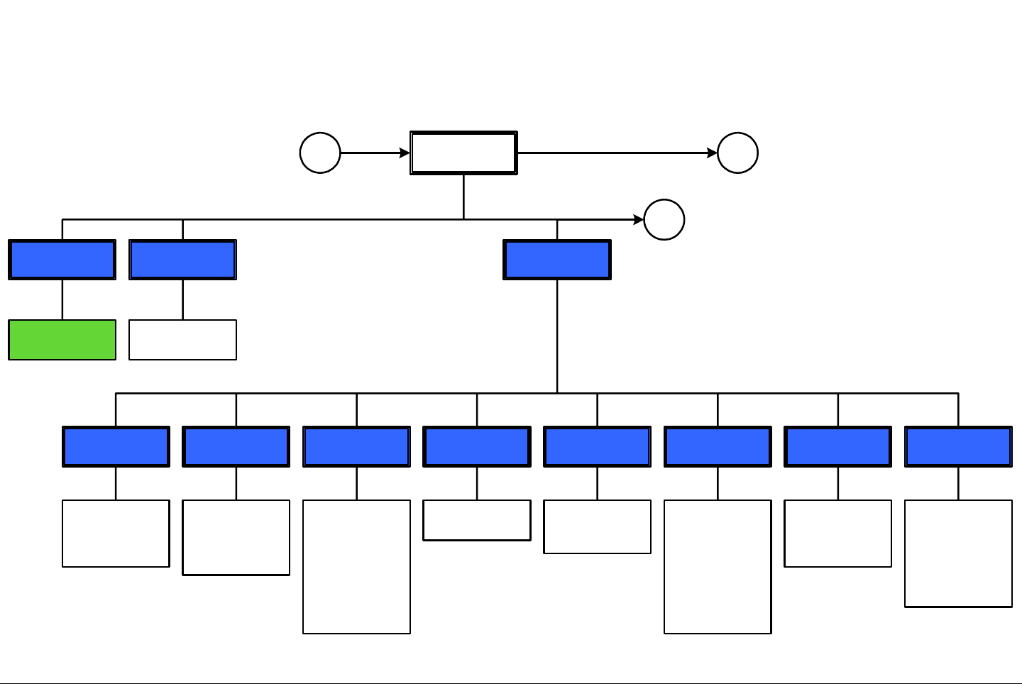
contained in your PTX-PRO is contained in Figure 5-1 on
page 5-4.
Advanced Operation 5-4PTX-PRO User and Technical Manual
Figure 5-1: Determine Licensed Options
MRC Configurator Icon
Main Page Licensing Tab
Licensed
Features
Record licensed
options
highlighted in
green
Main Tab
Radio Control
COM Port menu
Select COM port
required
Connect
Radio Mode,
MPEG, COFDM,
LMS-T, Channel
Plan, and
Licensing Tabs
are displayed
Disconnect
Close
Configurator
window
Radio Control
Advanced Operation 5-5PTX-PRO User and Technical Manual
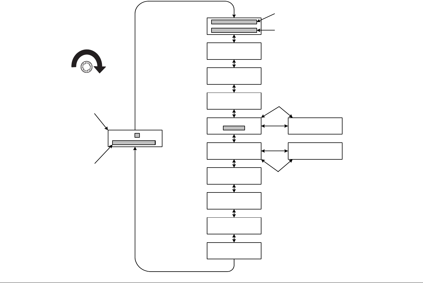
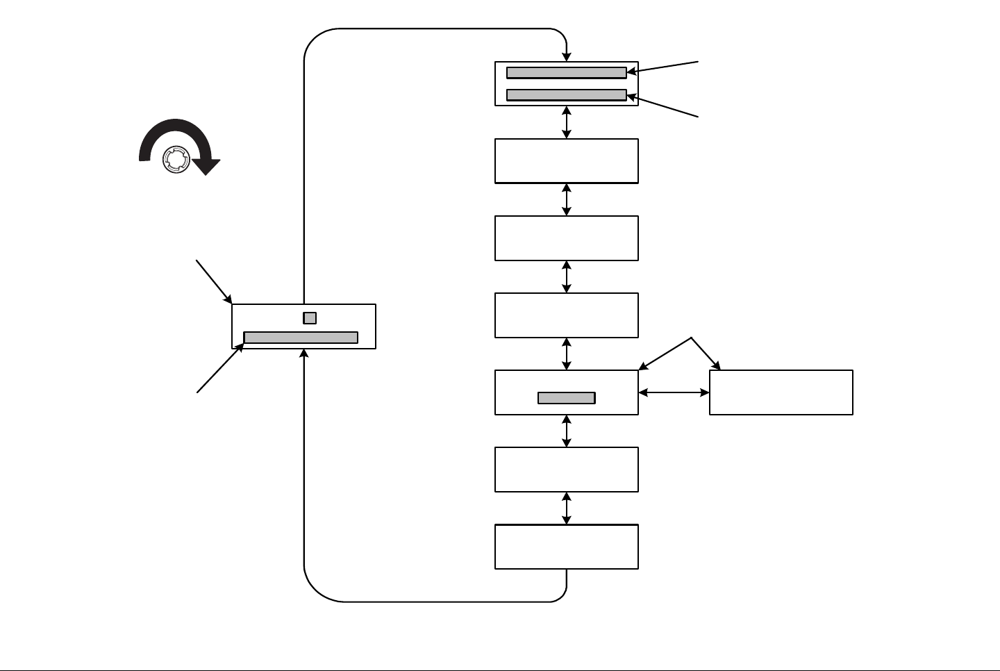
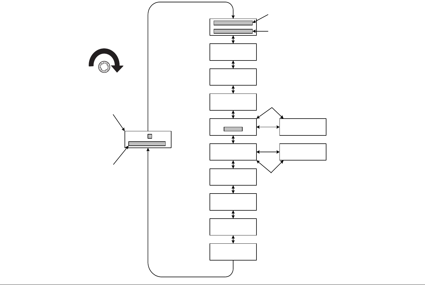
5.3.3 Create New Configuration On-Line
The flowchart required to create new Preset configuration settings
and channel plans in the on-line mode is contained in Figure 5-2
thru Figure 5-6.
Figure 5-2: Create New Configuration On-Line - Sheet 1 of 5
MRC Configurator Icon
Main Page
Radio Control
COM Port Menu
Select COM port
required
Connect
Radio Mode,
MPEG, COFDM,
LMS-T, Channel
Plan, and
Licensing tabs
are displayed
Preset
Operations
Change Preset
Names
Change Preset
Names Menu
Enter Preset
Names (12
characters max)
and select OK
Radio Mode Tab
Back Off (dB)
Enter back off
attenuation for
each Preset, as
required (Valid
range is 0 - 19)
Color Bars
Select OFF, ON,
Auto, or Standby
for each COFDM
and LMS-T
Preset, as
required
IF/CW Tone
Select OFF or
ON for each
COFDM Preset,
as required.
Operation Mode
Select COFDM,
ASI IN, Ext IF In,
or LMS-T for
each Preset, as
required
A
Remember Last
PA State Check
Box
Select check box,
as required
Note
If the Remember Last PA State option
is selected, the PTX-PRO will return to
the last state it was in when it was
powered down. If the radio was in
standby, it will return to standby upon
power up; if the radio was transmitting, it
will return to the transmitting state upon
power up.
To Figure 5-3
Advanced Operation 5-6PTX-PRO User and Technical Manual
Figure 5-3: Create New Configuration On-Line - Sheet 2 of 5
MPEG Tab
General Tab
ASI Rate
Enter ASI rate
required. If
Chroma setting
is 4:2:0, valid
range is 1.5 –
15.0; if Chroma
setting is 4:2:2,
valid range is
2.0 – 50.0
Chroma
Select 4:2:0 or
4:2:2, as required
Delay
Select Standard
or Low, as
required
HD Format
Select 720p50,
720p50, 729p60,
1080i25,
1080i29, or
1080i30, as
required (Active
in HD mode only)
HD/SD
Select HD or SD,
as required
(License required
for HD mode)
Input
Select SDI 525
IN, NTSC IN, or
NTSC No
Pedestal (Radio
Type NTSC) or
SDI 625 In, PAL
In, PAL M In, or
PAL N In (Radio
Type PAL)
Network
Enter Network
Name as
required (10
characters
Max)
Service
Enter Service
Name, as
required (10
characters Max)
Presets
Select Preset X,
as required
Radio Type
Select NTSC or
PAL, as required
A
B
Note
Perform all operations on the MPEG page for each
active Preset, as required.
C
From Figure 5-2
To Figure 5-4
To Figure 5-5
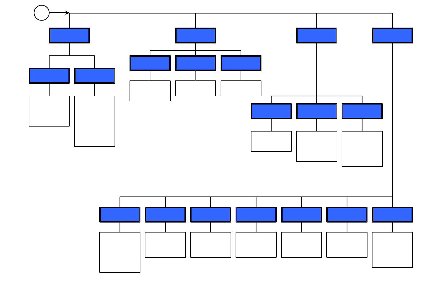
Advanced Operation 5-7PTX-PRO User and Technical Manual
Figure 5-4: Create New Configuration On-Line - Sheet 3 of 5
Audio A and
Audio B
Input
Select Test
Tone, Analog,
SDI EMB, or AES
EBU (Active in
MPEG mode
only)
Mode
Select Stereo or
Dual Mono, as
required (Active
in MPEG mode
only)
Type
Select OFF or
MPEG, as
required
Encryption PID Info
AUD-A
Enter Audio A
PID, as required
(Range is 32 -
8190)
AUD-B
Enter Audio B
PID, as required
(Range is 32 -
8190)
DAT
Enter data PID,
as required
(Range is 32 -
8190)
Default PID
If check box is
selected, default
PIDs will be used.
If check box is
not selected, PID
data must be
entered manually
PCR
Enter PCR PID,
as required
(Range is 32 -
8190)
Spectrum
Polarity
VID
Enter video PID,
as required
(Range is 32 -
8190)
Wayside
Baud
Select 1200,
2400, 4800,
9600, 19200, or
38400, as
required (Active
in IRD
Compatible and
Strata
Compatible only)
State
Select Off, IRD
Compatible, or
Strata
Compatible, as
required
B
Note
Enter PIDs only if Default PID was not checked.
If Default PID was checked, go to COFDM tab.
Type
Select OFF,
BISS-1, or BISS-
E, as required
Select Normal or
Inverted, as
required (Not
active on some
radio
configurations)
E Key and E ID 1 Key
Enter 1 Key data
Enter E Key and
E ID data
Note
BISS encryption is a factory-enabled option.
BISS options may only be selected if BISS has
been enabled at the factory.
From
Figure
5-3
Advanced Operation 5-8PTX-PRO User and Technical Manual
Figure 5-5: Create New Configuration On-Line - Sheet 4 of 5
COFDM Tab
Bandwidth
Select 6 MHz, 7
MHz, or 8 MHz,
as required
FEC
Select 1/2, 2/3,
3/4, 5/6, or 7/8,
as required
GuardModulation Type
Select 16 QAM,
64 QAM, or
QPSK, as
required
C
Note
Perform all operations on the COFDM page
for each active Preset, as required.
LMS-T Tab
Bandwidth
Select 10 MHz or
20 MHz, as
required
FEC
2/3 is the only
available option
Guard
Select 1/8 or
1/16, as required
Modulation Type
Select QPSK or
16 QAM, as
required
Note
Perform all operations on the LMS-T page for
each active Preset, as required.
D
Select 1/4, 1/8,
1/16, or 1/32, as
required
From
Figure 5-3
To
Figure
5-6
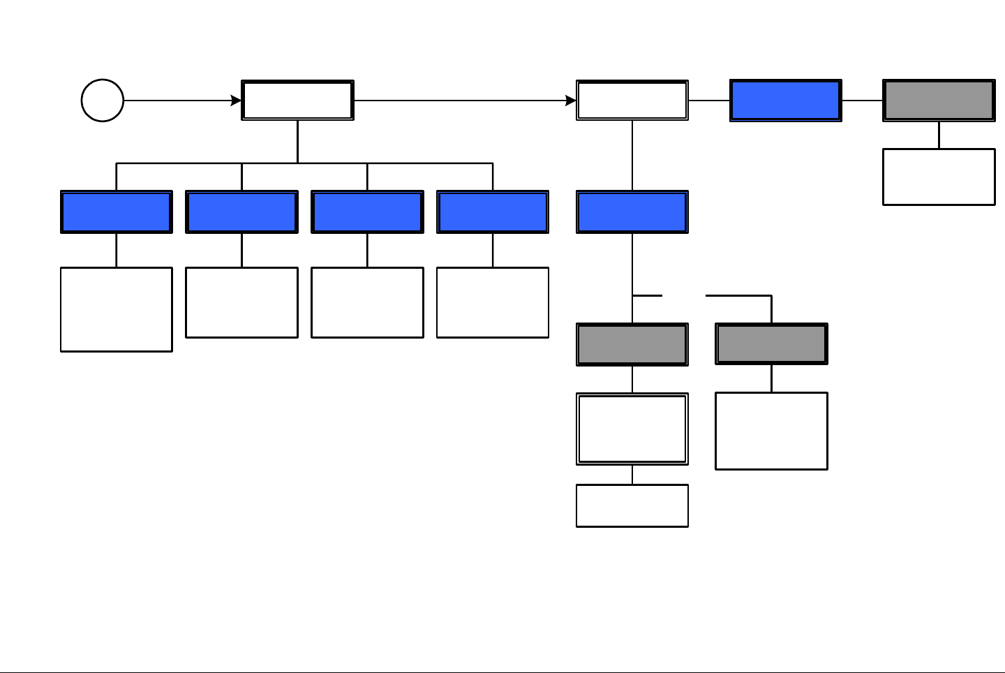
Advanced Operation 5-9PTX-PRO User and Technical Manual
Figure 5-6: Create New Configuration On-Line - Sheet 5 of 5
Channel Plan Tab
Center
Enter center
frequency for
each channel, as
required
Currently
Selected Band
Observe
Currently
Selected Band
indicates High
Band (13 GHz)
Offset +
Enter plus offset
frequency for
each channel, as
required
Offset -
Enter minus
offset frequency
for each channel,
as required
DMain Tab
Close
Configurator
Window
Radio Control
Save All Settings
to File
Save
Configuration
File window is
displayed
Save file
Program All
Settings to Radio
And/Or
Preset
configuration
settings are
loaded into the
radio.
DisconnectRadio Control
From
Figure
5-5
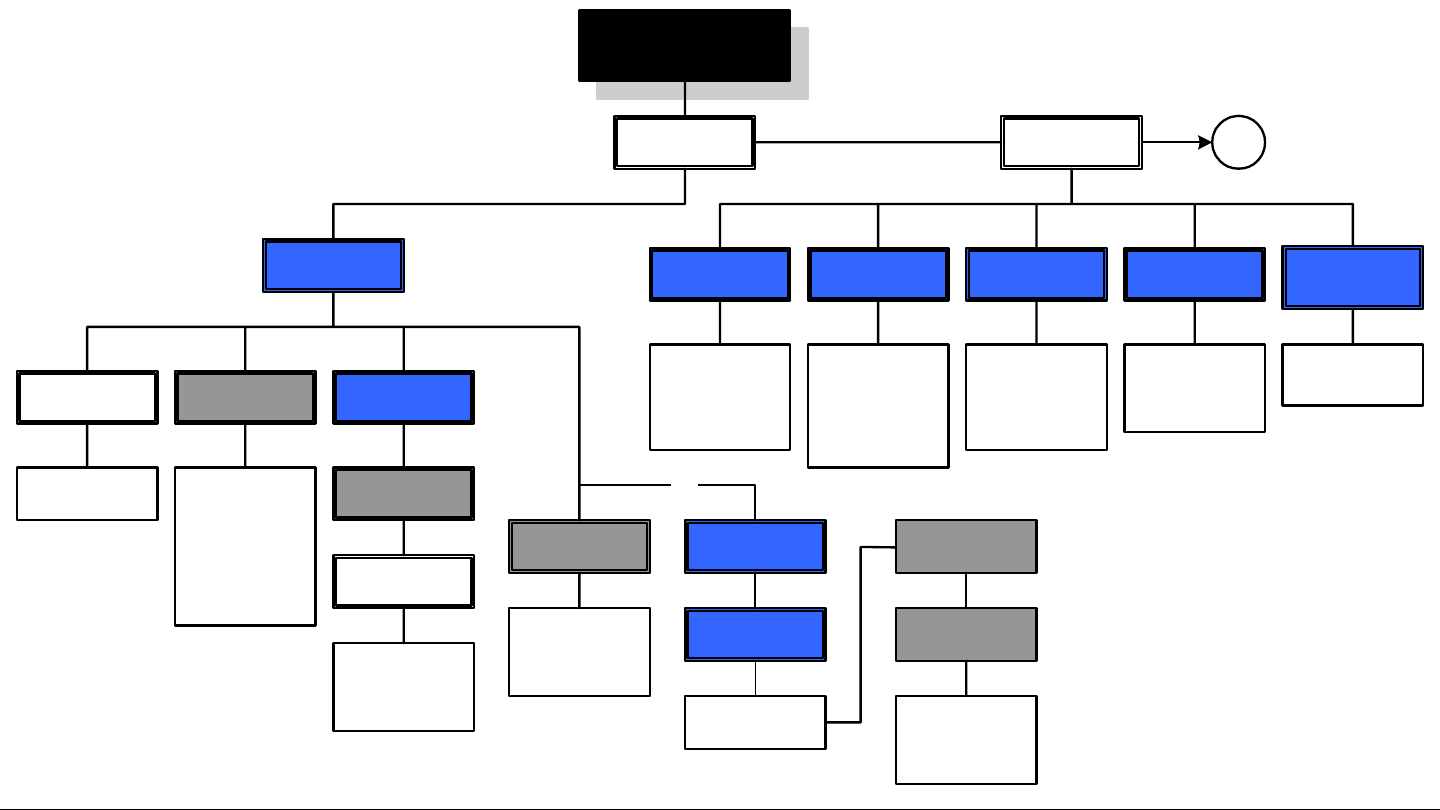
Advanced Operation 5-10PTX-PRO User and Technical Manual
5.3.4 Load and Modify Configuration Settings On- Line
The flowchart required to load Preset configuration settings and channel
plans from the radio and to modify the settings in the on-line mode is
contained in Figure 5-7 thru Figure 5-11.
Figure 5-7: Load and Modify Configuration Settings On-Line - Sheet 1 of 5
MRC Configurator Icon
Main Page
Radio Control
COM Port menu
Select COM
port required
Connect
Radio Mode,
MPEG,
COFDM, LMS-
T, Channel
Plan, and
Licensing
Tabs are
displayed
Load All Settings
from Radio
All Preset settings
and channel plans
are loaded into the
Configurator
Preset Operations
Change Preset
Names
Change Preset
Names Menu
Enter Preset
Names (12
characters
max)
Radio Mode Tab
Back Off (dB)
Enter back off
attenuation for
each Preset to
be modified
Color Bars
Select new
Color Bars
option for each
COFDM and
LMS-T Preset
to be modified
IF/CW Tone
Select new
IF/CW Tone
option for each
COFDM Preset
to be modified
Operation Mode
Select new
Operation
Mode option
for each Preset
to be modified
Remember Last
PA State Check
Box
Select check
box, as
required
A
Select Preset
Preset
Operations
Or-
Active Preset
Menu
Select Preset
required
Load Preset
Only the selected
Preset is loaded
into the
Configurator
To
Figure
5-8
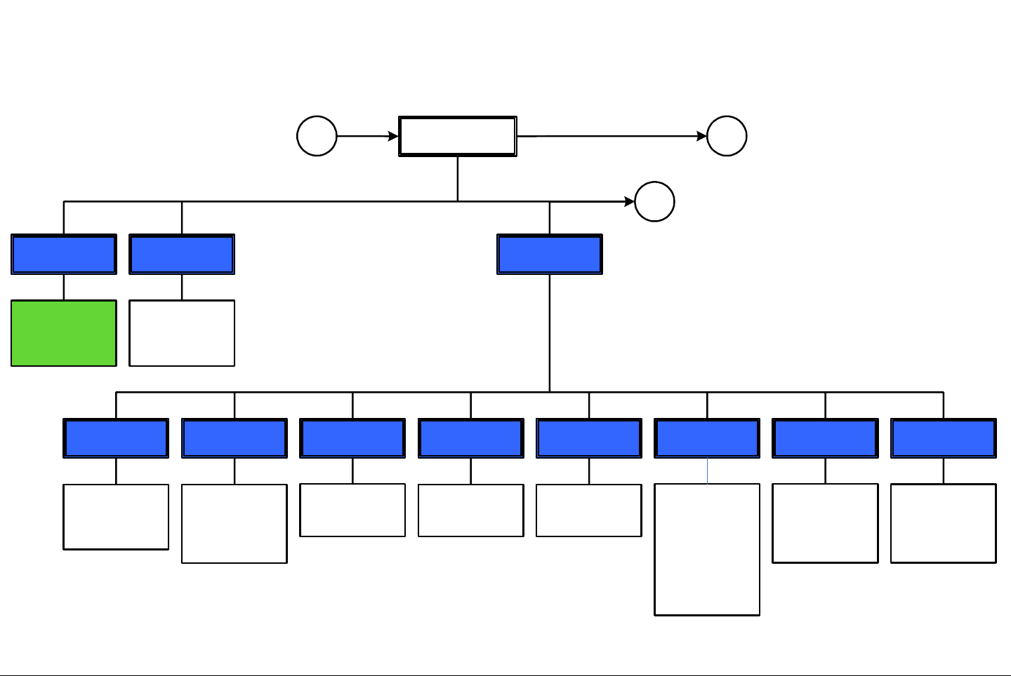
Advanced Operation 5-11PTX-PRO User and Technical Manual
Figure 5-8: Load and Modify Configuration Settings On-Line - Sheet 2 of 5
MPEG Tab
General Tab
ASI RateChroma
Select new
Chroma option,
as required
Delay
Select new
Delay option,
as required
HD Format
Select new HD
Format option,
as required
(Active in HD
mode only)
HD/SD
Select new HD or
SD option, as
required (License
required for HD
mode)
Input
Select new Input
option, as
required
Network
Modify Network
Name as
required (10
characters
Max)
Service
Modify Service
Name, as
required (10
characters Max)
Presets
Select Preset
X to be
modified, as
required
Radio Type
Select new
Radio Type
option, as
required
A
B
Note
Perform all operations on the MPEG page for each
active Preset to be modified, as required.
C
Change ASI rate,
as required. If
Chroma setting
is 4:2:0, valid
range is 1.5 –
15.0; if Chroma
setting is 4:2:2,
valid range is 2.0
– 50.0
From Figure 5-7
To Figure 5-9
To Figure 5-10
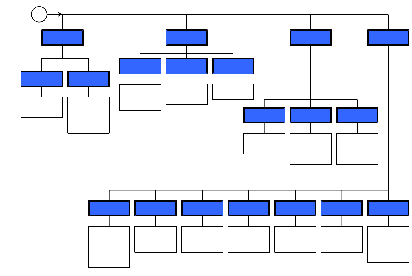
Advanced Operation 5-12PTX-PRO User and Technical Manual
Figure 5-9: Load and Modify Configuration Settings On-Line - Sheet 3 of 5
Audio A and
Audio B
Input
Select new Input
option, as
required (Active
in MPEG mode
only)
Mode
Select new Mode
option, as
required (Active
in MPEG mode
only)
Type
Select new audio
Type option, as
required
Encryption PID Info
AUD-A
Enter new Audio
A PID, as
required (Range
is 32 - 8190)
AUD-B
Enter new Audio
B PID, as
required (Range
is 32 - 8190)
DAT
Enter new data
PID, as required
(Range is 32 -
8190)
Default PID
If check box is
selected, default
PIDs will be used.
If check box is
not selected, PID
data must be
entered manually
PCR
Enter new PCR
PID, as required
(Range is 32 -
8190)
Spectrum VID
Enter new video
PID, as required
(Range is 32 -
8190)
Wayside
Baud
Select new Baud
rate, as required
(Active in IRD
Compatible and
Strata
Compatible only)
State
Select new State
option, as
required
B
Note
Enter PIDs only if Default PID was not checked.
If Default PID was checked, go to COFDM tab.
Type
Select new
encryption Type
option, as
required
Select new
Spectrum option,
as required (Not
active on some
radio
configurations
E Key and E ID 1 Key
Enter 1 Key data
Enter E Key and
E ID data, as
required
Note
BISS encryption is a factory-enabled option.
BISS options may only be selected if BISS has
been enabled at the factory.
From
Figure
5-8
Advanced Operation 5-13PTX-PRO User and Technical Manual
Figure 5-10: Load and Modify Configuration Settings On-Line - Sheet 4 of 5
COFDM Tab
Bandwidth
Select new
Bandwidth
option, as
required
FEC
Select new
forward error
correction (FEC),
as required
GuardModulation Type
Select new
Modulation
Type option, as
required
C
Note
Perform all operations on the COFDM page
for each active Preset, as required.
LMS-T Tab
Bandwidth
Select new
Bandwidth
option, as
required
FEC
2/3 is the only
available option
GuardModulation Type
Select new
Modulation
Type option, as
required
Note
Perform all operations on the LMS-T page for
each active Preset, as required.
D
Select new
Guard interval
option, as
required
Select new
Guard interval
option, as
required
To
Figure
5-11
From
Figure
5-8
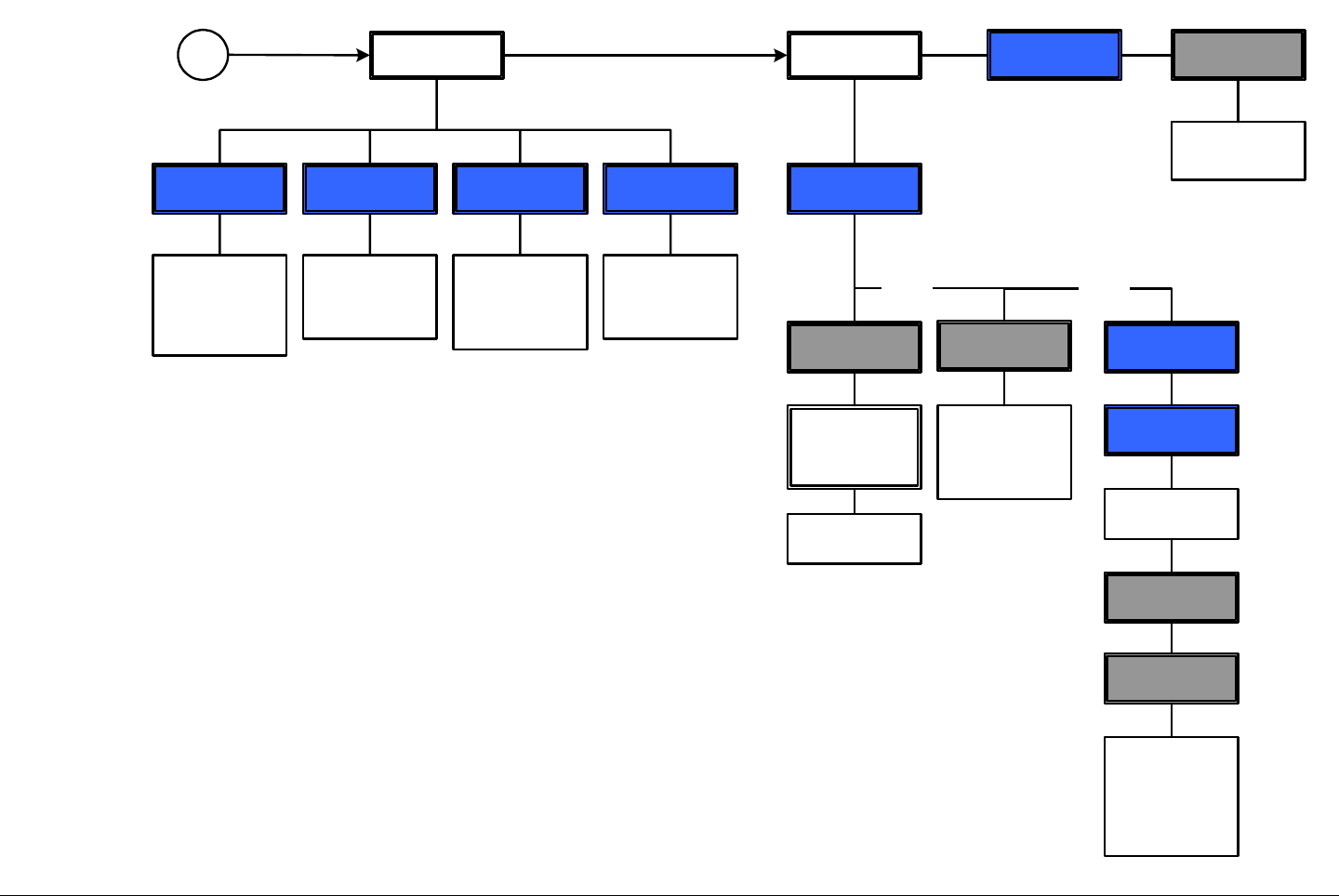
Advanced Operation 5-14PTX-PRO User and Technical Manual
Figure 5-11: Load and Modify Configuration Settings On-Line - Sheet 5 of 5
Channel Plan Tab
Center
Modify center
frequency for
each channel, as
required
Currently
Selected Band
Observe the
Currently
Selected Band
indicates High
Band (13 GHz)
Offset +
Modify plus offset
frequency for
each channel, as
required
Offset -
Modify minus
offset frequency
for each channel,
as required
DMain Tab
Close
Configurator
window
Radio Control
Save All
Settings to File
Save
Configuration
File window is
displayed
Save file
Program All
Settings to Radio
And/Or
Preset
configuration
settings are
loaded into the
radio.
Disconnect
Preset
Operations
And/Or
Active Preset
Menu
Select Preset
required
Select Preset
Program Preset
Configuration
settings for only
the selected
Preset are
programmed into
radio
Note
When Save All Settings to File is selected, all Preset
configuration settings and channel plan settings, not just
the Preset settings that were changed, are saved to a file.
When Program All Settings to Radio is selected, all
Preset configuration settings and channel plan settings,
not just the Preset settings that were changed, are
programmed into the radio.
When Program Preset is selected, only the selected
Preset is programmed into the radio.
Radio Control
From Figure
5-10
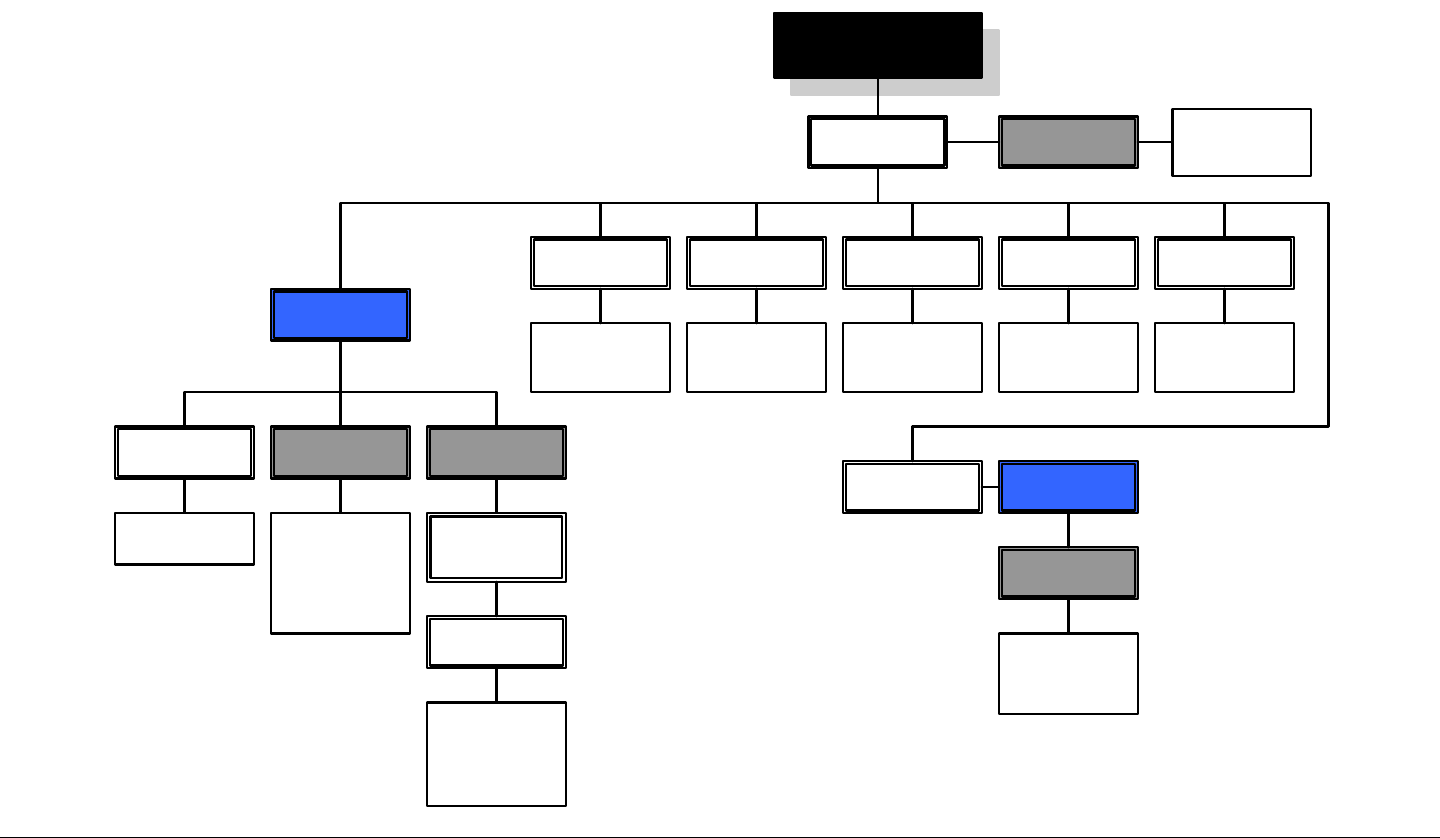
Advanced Operation 5-15PTX-PRO User and Technical Manual
5.3.5 Load Configuration File into Radio On-Line
The flowchart required to load a configuration and channel plan from
a file on your PC into your PTX-PRO is contained in Figure 5-12.
Figure 5-12: Load Configuration file into Radio On-Line
MRC Configurator Icon
Main Page
Channel Plan Tab
Review channel
plan(s) settings,
as required
COFDM Tab LMS-T TabMPEG Tab
Radio Control
COM port Menu
Select COM port
required
Connect
Radio Mode,
MPEG, COFDM,
LMS-T, Channel
Plan, and
Licensing Tabs
are displayed
Load All Settings
from File
Load
Configuration
File window
Open file
required
All Preset
settings and
channel plans are
loaded into
Configurator
Radio Mode Tab
Review
configuration
settings
Review
configuration
settings
Review
configuration
settings
Review
configuration
settings
Main Page Radio Control
Disconnect
Close
Configurator
window
Program All
Settings to Radio
All Preset
settings and
channel plans are
loaded into radio
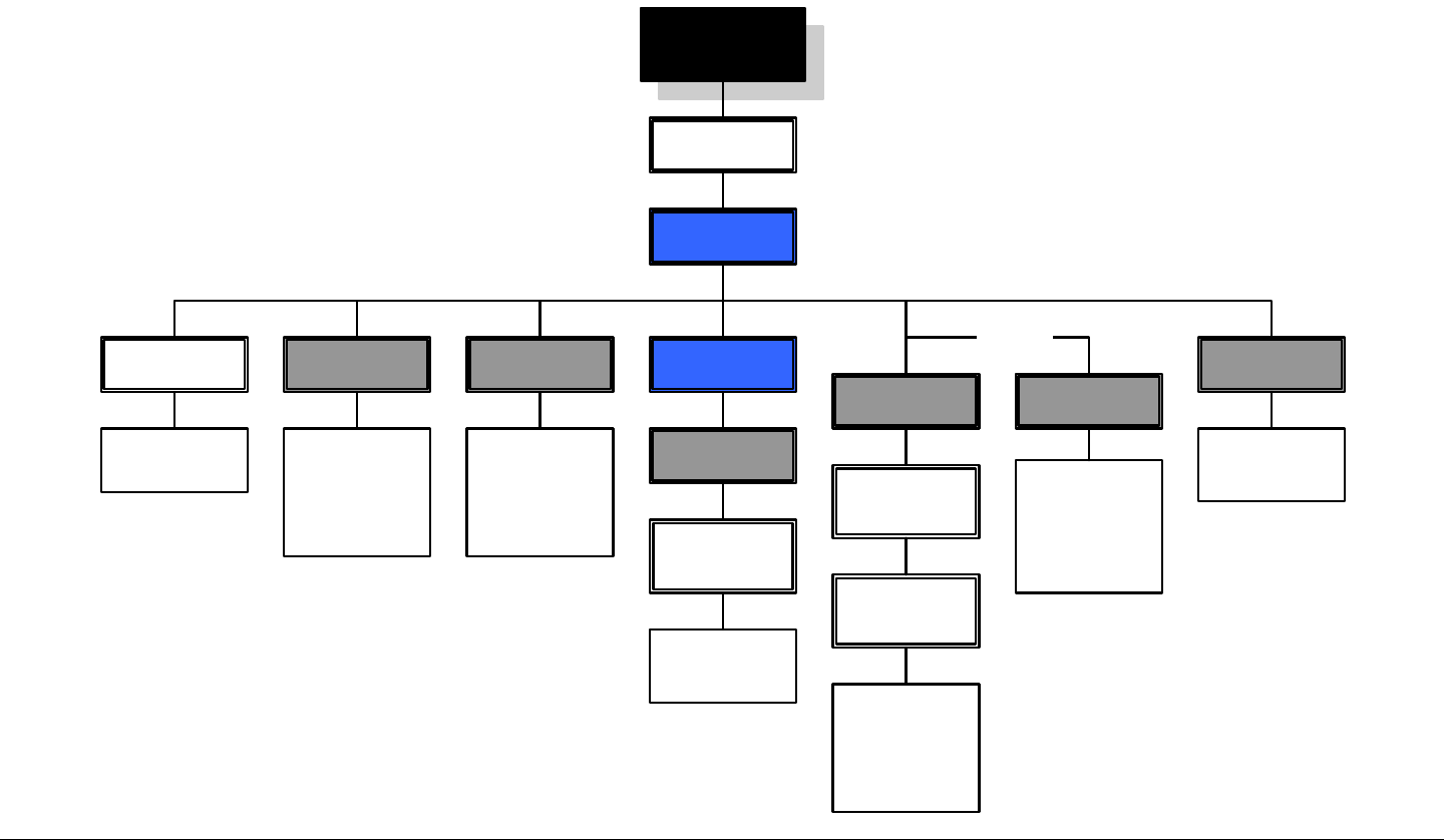
Advanced Operation 5-16PTX-PRO User and Technical Manual
5.3.6 Change Preset Names in On-Line Mode
The flowchart required to change Preset names in the on-line
mode is contained in Figure 5-13.
Figure 5-13: Change Preset Names in On-Line Mode
MRC Configurator
Icon
Main Page
Radio Control
COM Port Menu
Select COM port
required
Connect
Radio Mode,
MPEG, COFDM,
LMS-T, Channel
Plan, and
Licensing tabs
are displayed
Load All Settings
from Radio
All Preset names
and configuration
settings are
loaded into the
Configurator from
the radio
Preset
Operations
Change Preset
Names
Change Preset
Names Menu
Enter Preset
Names (12
characters Max)
Program All
Settings to Radio
Preset Names
and all
configuration
settings are
loaded into the
radio
Save All Settings
to File
Save
Configuration
File window
Saves
configuration file
to a PC
Preset Names
and all
configuration
settings are
saved to a file on
a PC
And/Orr
Close
Configurator
window
Disconnect

Advanced Operation 5-17PTX-PRO User and Technical Manual
5.3.7 Create Channel Plan Offline
The flowchart required to create new channel plans in the offline
mode is contained in Figure 5-14.
Figure 5-14: Create Channel Plan Offline
MRC Configurator Icon
Main Page Channel Plan Tab
Center
Review and
modify center
frequency for
each channel, as
required
Low Band Pull-
Down Menu
Select <Low
Band Disabled>
option
Close
Configurator
window
Start Offline
Programming
Offset +
Review and
modify plus offset
frequency for
channel 1 thru
21, as required
Offset -
Review and
modify minus
offset frequency
for channel 2 thru
22, as required
Offline
Programming
Radio Pull-Down
Menu
Select PTX-PRO
Dual Band
Save Bands to
File
Radio Mode,
MPEG, COFDM,
LMS-T, FMT,
Channel Plan,
and Licensing
tabs appear
Save
Configuration
File window
Save file
High Band Pull-
Down Menu
Select 13 GHz
(12.7 – 13.25)
option
Advanced Operation 5-18PTX-PRO User and Technical Manual
5.3.8 Modify Channel Plan in Offline Mode
The flowchart required to modify a channel plan contained in a file on
your PC is contained in Figure 5-15.
Figure 5-15: Modify Channel Plan in Offline Mode
MRC Configurator Icon
Main Page Channel Plan Tab
Center
Review and
modify center
frequency for
each channel, as
required
Close
Configurator
window
Start Offline
Programming
Offset +
Review and
modify plus offset
frequency for
channel 1 thru
21, as required
Offset -
Review and
modify minus
offset frequency
for channel 2 thru
22, as required
Offline
Programming
Radio Pull-Down
Menu
Select PTX-PRO
Dual Band
Save Bands to
File
Read Bands
from File
Load Channel
Plan
Configuration
File window
Open file required
Channel
frequencies are
displayed for all
channels and
bands, as
required
Radio Mode,
MPEG, COFDM,
LMS-T, FMT,
Channel Plan,
and Licensing
tabs appear
Save
Configuration
File window
Save file
Low Band Pull-
Down Menu
Select <Low
Band Disabled>
option
High Band Pull-
Down Menu
Select 13 GHz
(12.7 – 13.25)
option
Advanced Operation 5-19PTX-PRO User and Technical Manual
5.3.9 Load and Modify a Channel Plan On-Line
The flowchart required to load a channel plan in your radio and to
modify the plan in the on-line mode is contained in Figure 5-16.
Figure 5-16: Load and Modify a Channel Plan On-Line
MRC Configurator Icon
Main Page
Channel Plan Tab
Center
Modify center
frequency for
each channel, as
required
Currently
Selected Band
Verify Currently
Selected Band is
High Band (13
GHz)
Load Current
Band from Radio
Current selected
band is loaded
into the
Configurator
Offset +
Modify plus offset
frequency for
channel 1 thru
21, as required
Offset -
Modify minus
offset frequency
for channel 2 thru
22, as required
Radio Control
COM Port Menu
Select COM port
required
Connect
Radio Mode,
MPEG, COFDM,
LMS-T, Channel
Plan, and
Licensing Tabs
are displayed
Program Current
Band to Radio
Program All
Bands to Radio
Orr
Main Tab Radio Control Disconnect
Close
Configurator
window
Current selected
band is loaded
into the radio
The High Band
(13 GHz) channel
plan is loaded
into the radio
Save Bands
to Flie
Save
Configuration
File window is
displayed
Save file
And/Orr
Note
When Save Bands to File is selected, only
channel plan settings are saved to a file. No
Preset settings are saved to the file.
When Program Current Band to Radio or
Program All Bands to Radio is selected, only
channel plan settings are programmed into the
radio. No Preset settings are programmed into
the radio.
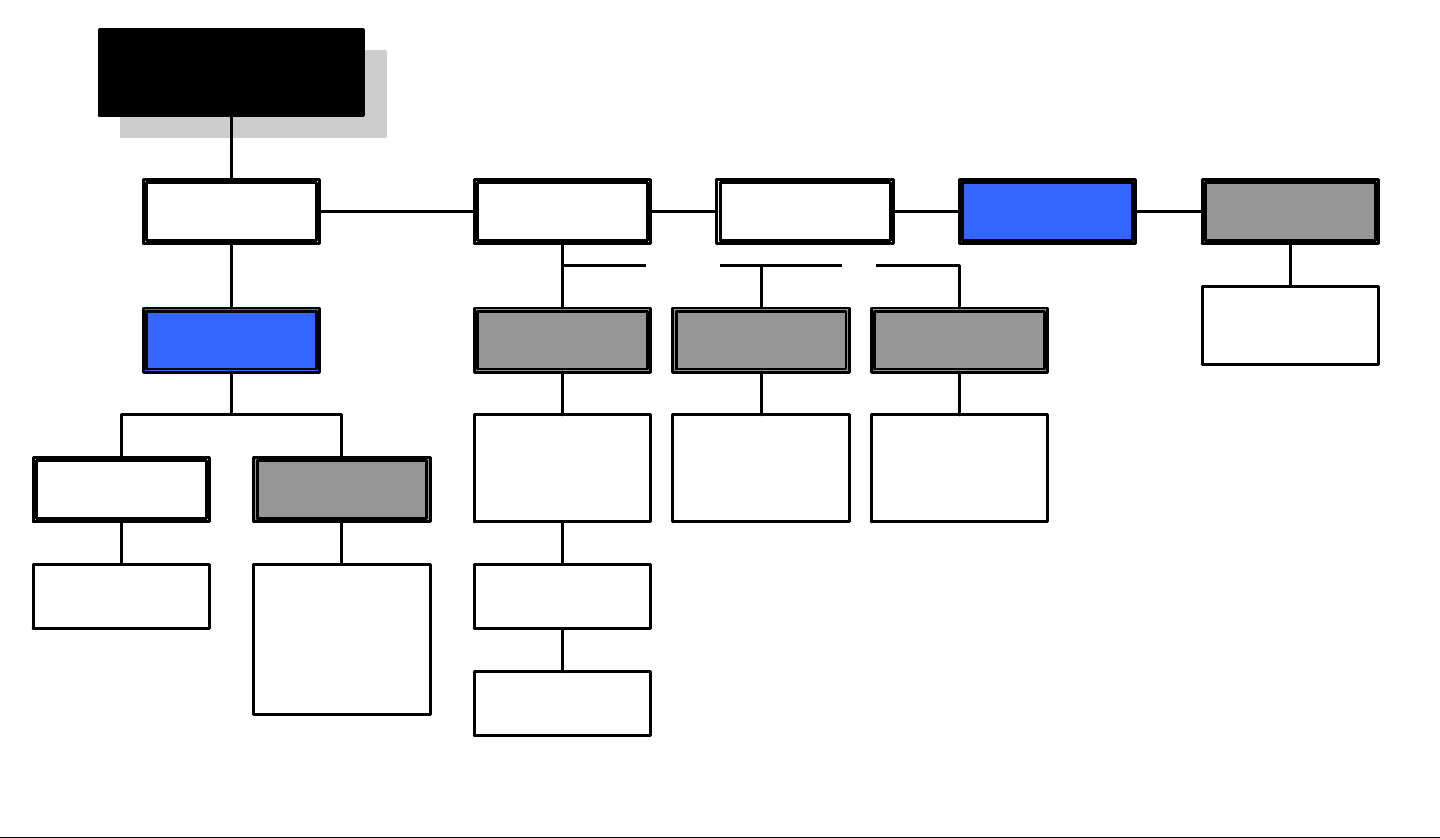
Advanced Operation 5-20PTX-PRO User and Technical Manual
5.3.10 Load Channel Plan File into Radio On-Line
The flowchart required to load a channel plan from a file on your PC
into your PTX-PRO in the on-line mode is contained in Figure 5-17.
Figure 5-17: Load Channel Plan into Radio in On-Line Mode
MRC Configurator Icon
Main Page Channel Plan Tab
Read Bands
from File
Load Channel
Plan
Configuration
File window
Select file
required
Selected file is
loaded into radio
Radio Control
COM Port Menu
Select COM port
required
Connect
Radio Mode,
MPEG, COFDM,
LMS-T, Channel
Plan, and
Licensing Tabs
are displayed
Disconnect
Close
Configurator
window
Radio ControlMain Tab
Program Current
Band to Radio
Program All
Bands to Radio
Orr
The High Band
(13 GHz) channel
plan is loaded
into the radio
And/Orr
The High Band
(13 GHz) channel
plan is loaded
into the radio
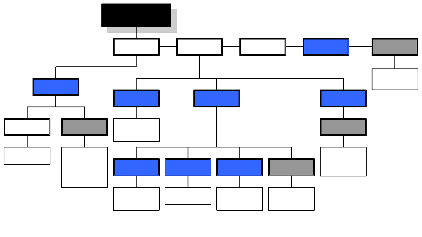
Advanced Operation 5-21PTX-PRO User and Technical Manual
5.3.11 Add Licensed Option
The flowchart required to add new licensed options to your PTX-PRO
is contained in Figure 5-18. The license required to add a new licensed
feature must be obtained from MRC prior to performing this procedure.
Figure 5-18: Add Licensed Option
MRC Configurator Icon
Main Page
Radio Control
COM Port Menu
Select COM port
required
Connect
Radio Mode,
MPEG, COFDM,
LMS-T, Channel
Plan, and
Licensing Tabs
are displayed
Licensing Tab
Licensed
Features
All current
licensed features
are listed
Refresh
New Licensed
Feature is listed
in Licensed
column
MPEG
Information
Firmware Number
Current firmware
revision is listed
License Key
Enter license key
obtained from
MRC in text box
Serial Number
Serial number of
software module
is listed
Set Key
Select Set Key
option button to
enable license
Licensed
Features
Disconnect
Close
Configurator
window
Radio ControlMain Tab

Advanced Operation 5-22PTX-PRO User and Technical Manual

6
Installation 6-1PTX-PRO User and Technical Manual
Installation
6.1 Chapter Overview
This chapter describes how to unpack and install your PTX-PRO
13 GHz Transmitter (PTX-PRO). The topics covered in this
chapter are as follows:
6.2 Unpacking
Each PTX-PRO is shipped assembled, wired, and factory tested.
Each unit is packaged in appropriate shipping containers.
Here are some tips to help you with unpacking your new
equipment:
• Unpack the equipment carefully to avoid accidental
damage.
Topic Page
Unpacking 6-1
Initial Inspection 6-1
Damage in Shipment 6-1
Mounting and Cabling 6-2
Power Connections 6-5
Grounding 6-8
Audio Connections 6-8
Signal Connections 6-11
Data Connections 6-11
Powering Up 6-16
Configurator Software Installation 6-17
Product Modifications 6-20
• Be sure to locate all parts and accessories.
• Verify that the items shipped agree with those listed on
the packing list.
• DO NOT discard the container or packing material until
you have inspected the equipment and are sure there is
no shipping damage. The container and packing must be
available in the event that a damage claim needs to be
filed with the shipping carrier.
6.3 Initial Inspection
After the equipment is unpacked, we recommend you inspect it
using the following checklist:
• Check for any dents or scratches.
• Check that the equipment is clean and dry.
• Check that no cables or connectors are broken, damaged,
or loose.
• Check that no switches or LED indicators are broken,
damaged, or loose.
6.4 Damage in Shipment
Should any damage be discovered after unpacking the unit, use
the following procedure:
• Immediately file a claim with the shipping carrier.
• Forward a copy of the damage report to MRC Customer
Service.
• Contact MRC Customer Service to determine the
disposition of the equipment.
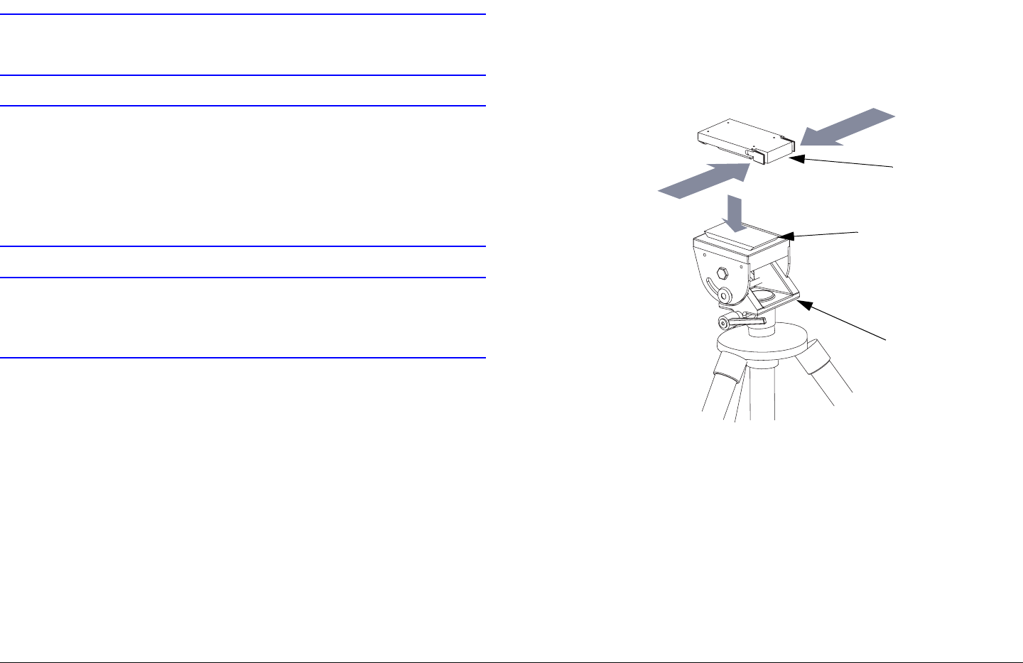
Installation 6-2PTX-PRO User and Technical Manual
6.5 Mounting and Cabling
CAUTION Be sure the power being supplied matches
the power required by the equipment.
CAUTION Power supply cords and cables must be
protected. Do not run cords where they can
be walked upon. Protect cables against
pinching and chafing. Pay special attention
to locations where the cables enter or exit
an enclosure or make a sharp bend.
CAUTION Ensure that the electrical supply is protected
by over-current protection devices, as
required by the applicable electrical codes.
Each installation or deployment will have its own specific tasks
according to the application and the installed hardware. The
following section describes mounting and cabling the PTX-PRO.
6.5.1 Portable Deployment
For portable applications, the PTX-PRO will typically be moved
from place to place and set up each time. The power, antenna,
and audio/video connections are usually removed at the end of
each deployment.
Mounting - MRC Tripod The PTX-PRO will typically be
attached to a Quick Release Mount for easy mounting on an
MRC tripod. The Quick Release Mount is attached to the bottom
of the PTX-PRO using four 1/2-inch long, #6-32, flat head
screws. The Quick Release Mount typically remains attached to
the PTX-PRO. The Quick Release Mount and PTX-PRO are
then attached to the Dovetail Adapter Plate machined into the
MRC tripod mount. See Figure 6-1.
Figure 6-1: Quick Release Mount on MRC Tripod
Quick
Release
Mount
Dovetail Adapter
Plate (Machined)
MRC Tripod
Mount

Installation 6-3PTX-PRO User and Technical Manual
Note The versatility of the Quick Release Mount and a
mating Dovetail Adapter Plate allow the Dovetail
Adapter Plate to be attached to the bottom of the
PTX-PRO and the Quick Release Mount to be
attached to a non-MRC tripod, or vice versa. The
method you use to attach the PTX-PRO to a non-
MRC tripod is your choice.
Optional mounting procedures and illustrations to
mount your PTX-PRO on non-MRC tripods are
provided in the following paragraphs.
Mounting - Non-MRC Tripod (Option 1) To mount a PTX-PRO
on a non-MRC tripod, one option is to attach the Quick Release
Mount to the bottom of the PTX-PRO using four 1/2-inch long,
#6-32, flat head screws.
The Dovetail Adapter Plate is then attached to the non-MRC
tripod and the Quick Release Mount and PTX-PRO assembly is
attached to the Dovetail Adapter Plate on the tripod mount.
See Figure 6-2.
Figure 6-2: Dovetail Adapter Plate on Non-MRC Tripod
Mounting - Non-MRC Tripod (Option 2) To mount a PTX-PRO
on a non-MRC tripod, another option is to attach the Dovetail
Adapter Plate to the bottom of the PTX-PRO using four 1/2-inch
long, #6-32, flat head screws.
The Quick Release Mount is then attached to the non-MRC
tripod and the Dovetail Adapter Plate and PTX-PRO assembly is
attached to the Quick Release Mount on the tripod mount. See
Figure 6-3 on page 6-4.
Quick Release
Mount (Attached to
PTX-PRO)
Flat Head Screws
(4 Each)
Dovetail
Adapter
Plate
Tripod
Mount
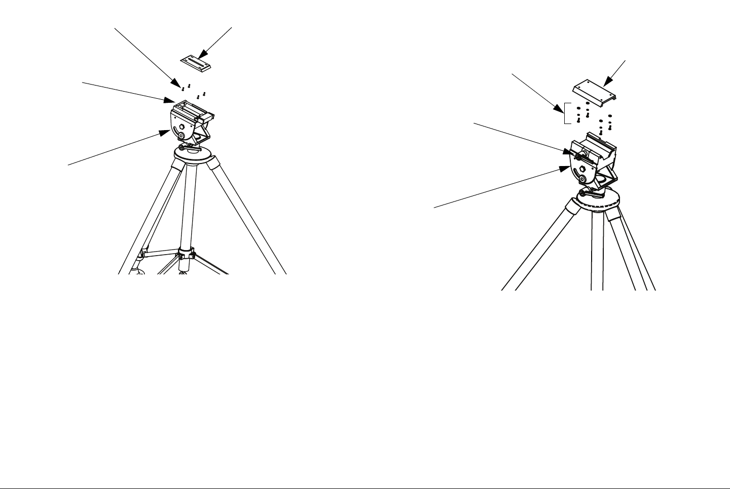
Installation 6-4PTX-PRO User and Technical Manual
Figure 6-3: Quick Release Mount on Non-MRC Tripod
Mounting - Non-MRC Tripod (Option 3) A third option is
available to mount a PTX-PRO to a non-MRC tripod that
contains a QuickSet tripod mount. This option requires the use
of a QuickSet Quick Change Adapter. The Quick Change
Adapter is attached to the bottom of the PTX-PRO using four
1/2-inch long, #6-32, pan head screws, lock washers, and flat
washers.
The Quick Change Adapter and PTX-PRO assembly is then
attached to the QuickSet tripod mount and is secured with the
tripod mount locking clamp. See Figure 6-4.
Flat Head Screws
(4 Each)
Quick
Release
Mount
Dovetail Adapter
Plate (Attached to
PTX-PRO)
Tripod
Mount
Figure 6-4: Quick Change Adapter on QuickSet Tripod
Mount - Typical
Final Mounting When the PTX-PRO is mounted on the tripod,
the antenna is typically attached to the Antenna Lock Plate
mounted on the PTX-PRO. See Figure 6-5 on page 6-5.
Pan Head Screws,
Lock Washers, and
Flat Washers (4 Each)
Tripod Mount
Locking Clamp
QuickSet Quick
Change Adapter
(Attached to PTX-
PRO)
QuickSet
Tripod
Mount
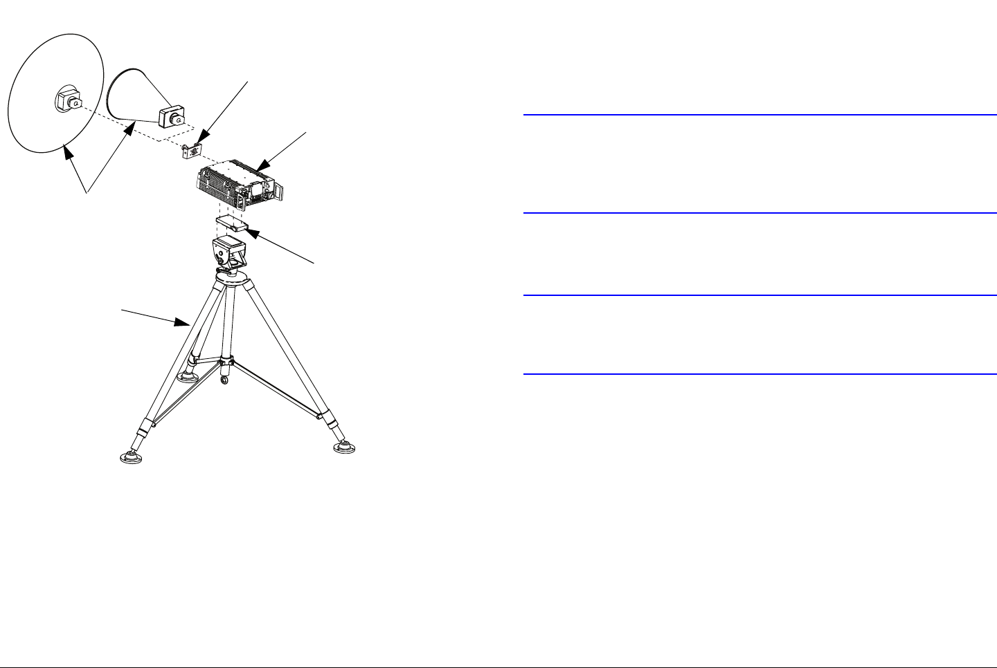
Installation 6-5PTX-PRO User and Technical Manual
Figure 6-5: Complete Tripod Installation - Typical
6.6 Power Connections
6.6.1 Power Requirements
The PTX-PRO has the following power requirements, depending
upon the power option utilized.
Supply Voltage: +11.0 to +36 Volts DC
90 to 264 VAC, 50/60 Hz
Quick Release
Mount
PTX-PRO (Typical)
Antenna Lock
Plate
Antenna
(2 Options
Shown)
Tripod
Power Consumption: 50 watts nominal
6.6.2 Power Supply and Distribution
AC or DC power is supplied externally, from an external power
source.
CAUTION Avoid possible equipment damage. If you
are using a DC power source for your PTX-
PRO, do not exceed 36 volts DC input
power.
Power is distributed to the PTX-PRO through the front panel
PWR connector on the PTX-PRO.
CAUTION To avoid possible equipment damage, turn
off DC Power on the coax before connecting
any test equipment.
Panel Power Connections The PTX-PRO power connector is
located on the front panel. The mating connector that plugs into
this panel connector is described below.
Manufacturer: ITT Cannon
Part Number KPTR06F14-12SX
Description: 12-Pin, Female, Plug
Manufacturer: Amphenol
Part Number PT06E14-12SX
Description: 12-Pin, Female, Plug
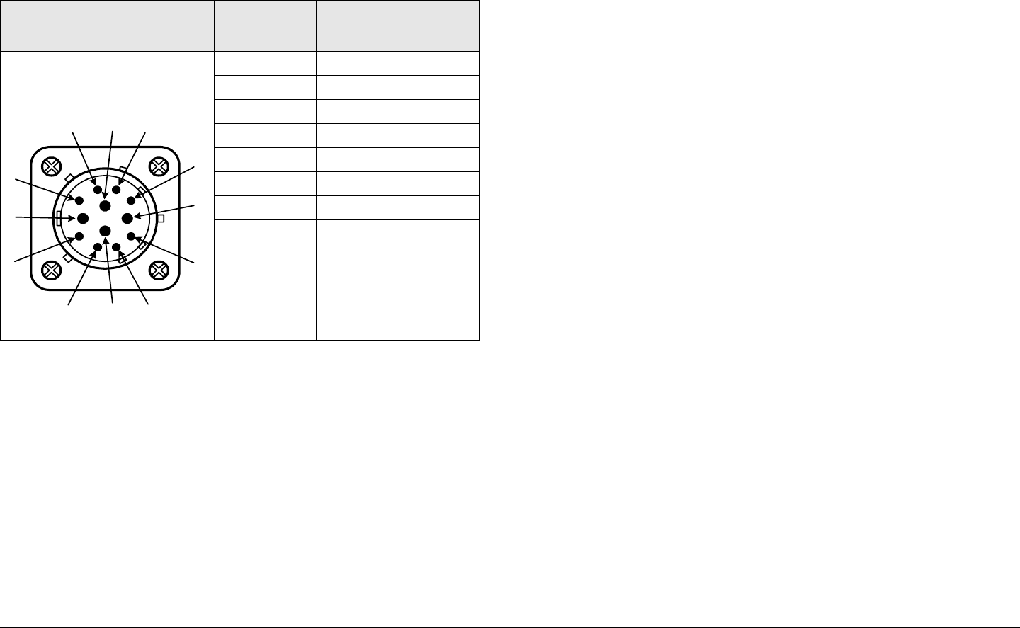
Installation 6-6PTX-PRO User and Technical Manual
Pin designations on the front panel PWR connector are shown in
Table 6-1.
Table 6-1: Front Panel AC/DC Power Connector Pin-Outs
6.6.3 Power Cable Assemblies
The PTX-PRO contains a universal AC/DC power supply and
can operate on either external AC or DC power sources. Power
cable assemblies are available from MRC for the PTX-PRO
based on the power to be used.
AC Power Cable Assemblies Prefabricated AC Power Cable
Assemblies are available from MRC to connect the PTX-PRO
PWR connector to either 120 VAC or 240 VAC (nominal).
The AC Power Cable Assemblies are 6.0 ft. (1.8 m) long. The
120 VAC Power Cable Assembly comes complete with power
connectors on both ends. See Figure 6-6 on page 6-7 for the
Connector Information Pin-Out Signal
Description
12-Pin, Male, Panel-Mount A 90 to 264 VAC
BN/C
C Neutral
DN/C
EN/C
FN/C
GN/C
HN/C
J DC (+)
K DC (-)
L AC Ground / DC (-)
M DC (+)
A
B
C
D
E
F
G
HJ
K
L
M
wiring diagram of the 120 VAC Power Cable Assembly.
The 240 VAC Power Cable Assembly comes with a power
connector on one end only. The user must provide the input
power connector for the 240 VAC version of the Power Cable
Assembly. See Figure 6-7 on page 6-7 for the wiring diagram of
the 240 VAC Power Cable Assembly.
DC Power Cable Assembly A prefabricated DC Power Cable
Assembly is available from MRC to connect the PTX-PRO PWR
connector to a DC power source.
The DC Power Cable Assembly is 10 ft. (3 m) long. The DC
Power Cable Assembly comes with a power connector on one
end only. See Figure 6-8 on page 6-7 for the wiring diagram of
the DC Power Cable Assembly.
Power Cable Fabrication If it is necessary to fabricate your
own AC or DC power cable assembly, 20 AWG stranded wire is
recommended for lengths up to 10 feet (3 m). Use one wire per
connector contact. The mating connector for the PTX-PRO
PWR connector is described in “Panel Power Connections” on
page 6-5. Consult the factory if you need longer cabling.
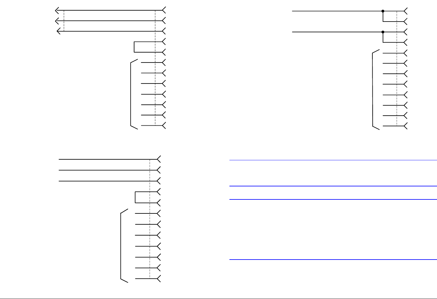
Installation 6-7PTX-PRO User and Technical Manual
Figure 6-6: 120 AC Power Cable Assembly
Figure 6-7: 240 VAC Power Cable Assembly
White
Black
Green
C
A
L
E
F
B
D
G
H
J
K
M
NC
120 VAC
Neutral
Ground
White
Black
Green
C
A
L
E
F
B
D
G
H
J
K
M
NC
Neutral
240 VAC
Ground
Figure 6-8: DC Power Cable Assembly
6.6.4 Additional Powering Notes
CAUTION Be sure the power being supplied matches
the power required by the equipment.
CAUTION Power supply cords and cables must be
protected. Do not run cords where they can
be walked upon. Protect cables against
pinching and chafing. Pay special attention
to locations where the cables enter or exit
an enclosure or make a sharp bend.
Black
Red
C
A
L
E
F
B
D
G
H
J
K
M
NC
DC Negative
DC Positive
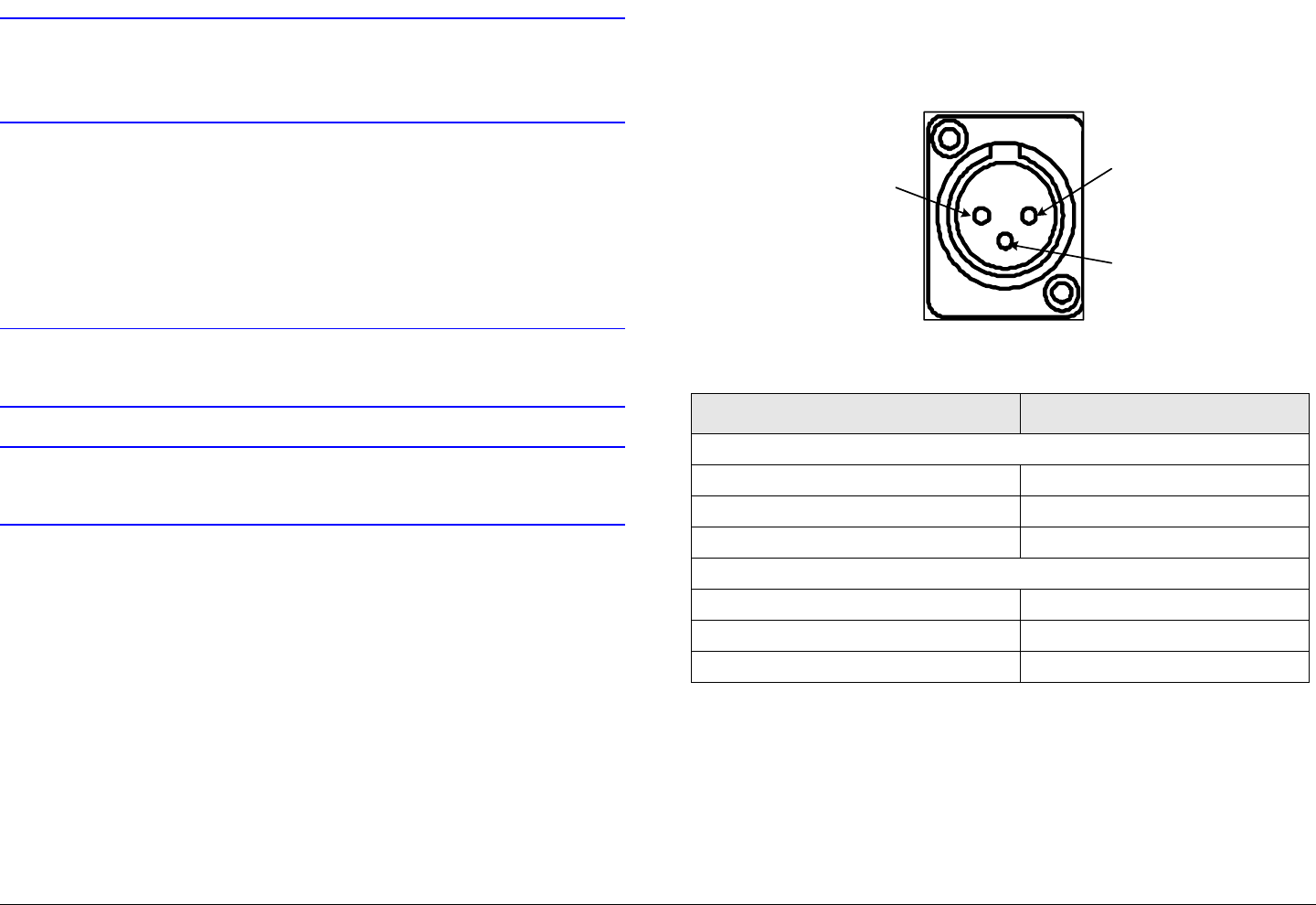
Installation 6-8PTX-PRO User and Technical Manual
CAUTION Ensure that the electrical supply is protected
by over-current protection devices, as
required by the applicable electrical codes.
Check the electrical supply to be sure it can provide all the power
needed at the site without overloading. Power ratings for
equipment can be found on a rating plate, usually on the rear
panel. If necessary, consult a licensed electrician.
6.7 Grounding
CAUTION Be sure the equipment grounding follows
applicable electrical codes.
CAUTION Never modify a grounded power plug to
connect to an ungrounded receptacle.
The equipment must be connected to the common ground on the
installation. This common ground is often the vehicle or aircraft
ground. The ground wire should be as short as possible, and
should follow the straightest path possible.
6.8 Audio Connections
All PTX-PRO audio inputs are applied to either the front or rear
panel audio connectors.
6.8.1 Front Panel Audio Connections
Front panel AUDIO 1 and AUDIO 2 XLR connectors are used for
both Audio A inputs. Connector pin-outs are shown in Figure 6-
9. Pin-out connections are shown in Table 6-2.
Figure 6-9: XLR Connector Pin-Outs
Table 6-2: XLR Connector Pin-Outs
A prefabricated cable assembly (See Figure 6-10 on page 6-10)
is available that splits the audio connections into two separate
cables with XLR connectors. The two connectors are labelled
Audio 1 and Audio 2. One cable assembly is included with
each PTX-PRO ordered.
Should you need additional cables, contact MRC Customer
Service.
Panel Connector Pin Function
AUDIO 1
1Ground
2Live (+)
3 Return (-)
AUDIO 2
1Ground
2Live (+)
3 Return (-)
1
2
3
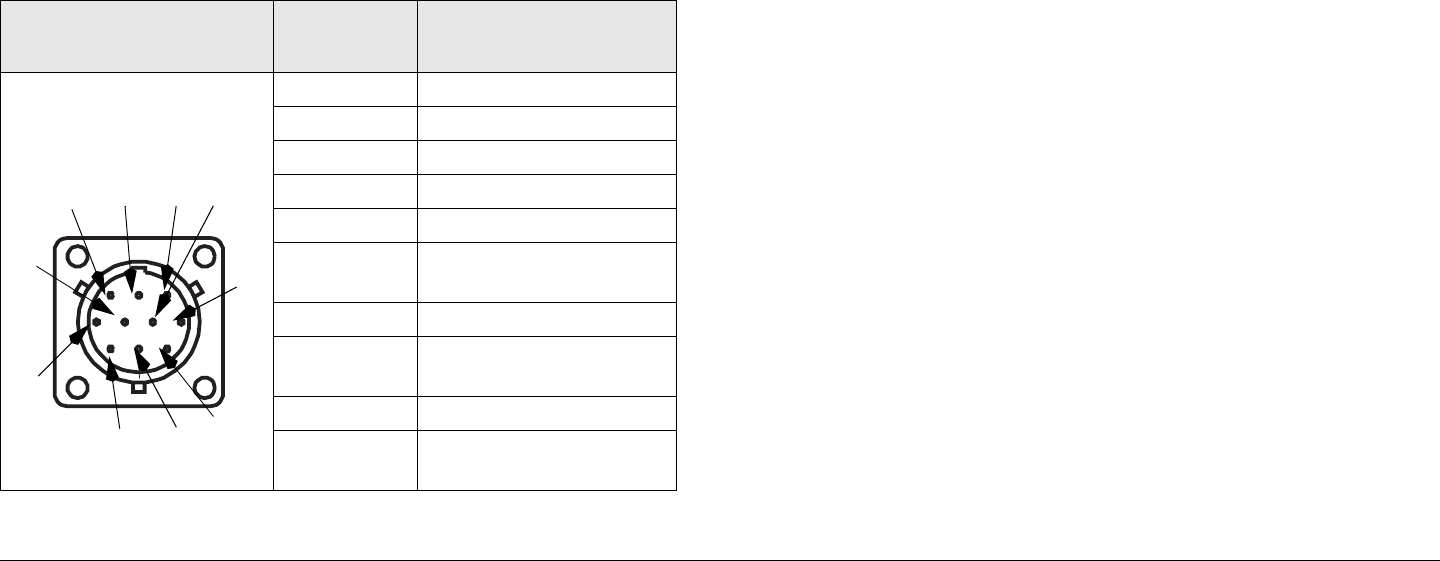
Installation 6-9PTX-PRO User and Technical Manual
6.8.2 Rear Panel Audio Connections
The rear panel AUDIO 3 & 4 10-pin female connector receives
balanced audio inputs for audio channels 3 and 4. This
connector is used for both Audio B inputs.
The mating connector that plugs into this panel connector is
described below.
Manufacturer: Amphenol (or ITT Cannon)
Part Number MS3116F12-10S (KPT06F12-10S)
Description: 10-Pin, Female, Plug
Rear panel AUDIO 3 & 4 connector pin-outs are shown in Table
6-3.
Table 6-3: Rear Panel Audio Connector Pin-Outs
Connector
Information Pin-Out Signal Description
10-Pin, Male, Panel-
Mount
A DIGITAL 1 CH1 +
B DIGITAL 1/2 GND
C DIGITAL 1 CH1 -
D DIGITAL 2 CH2 +
E DIGITAL 2 CH2 -
F ANALOG 3 RIGHT
CH2 -
G ANALOG 3/4 COM
H ANALOG 3 RIGHT
CH2 +
J ANALOG 4 LEFT CH2 -
K ANALOG 4 LEFT
CH2 +
HABJ
C
D
E
F
G
K
The PTX-PRO provides a maximum of four audio circuits. Each
audio circuit is a 3-wire balanced circuit capable of carrying one
tone or voice signal. An audio circuit can carry one analog
balanced channel or two digital AES/EBU channels.
6.8.3 MPEG Audio Input
MPEG audio circuits must be configured in pairs:
•Audio A - Channels 1 and 2
•Audio B - Channels 3 and 4
Audio channels are configured using the Configurator software.
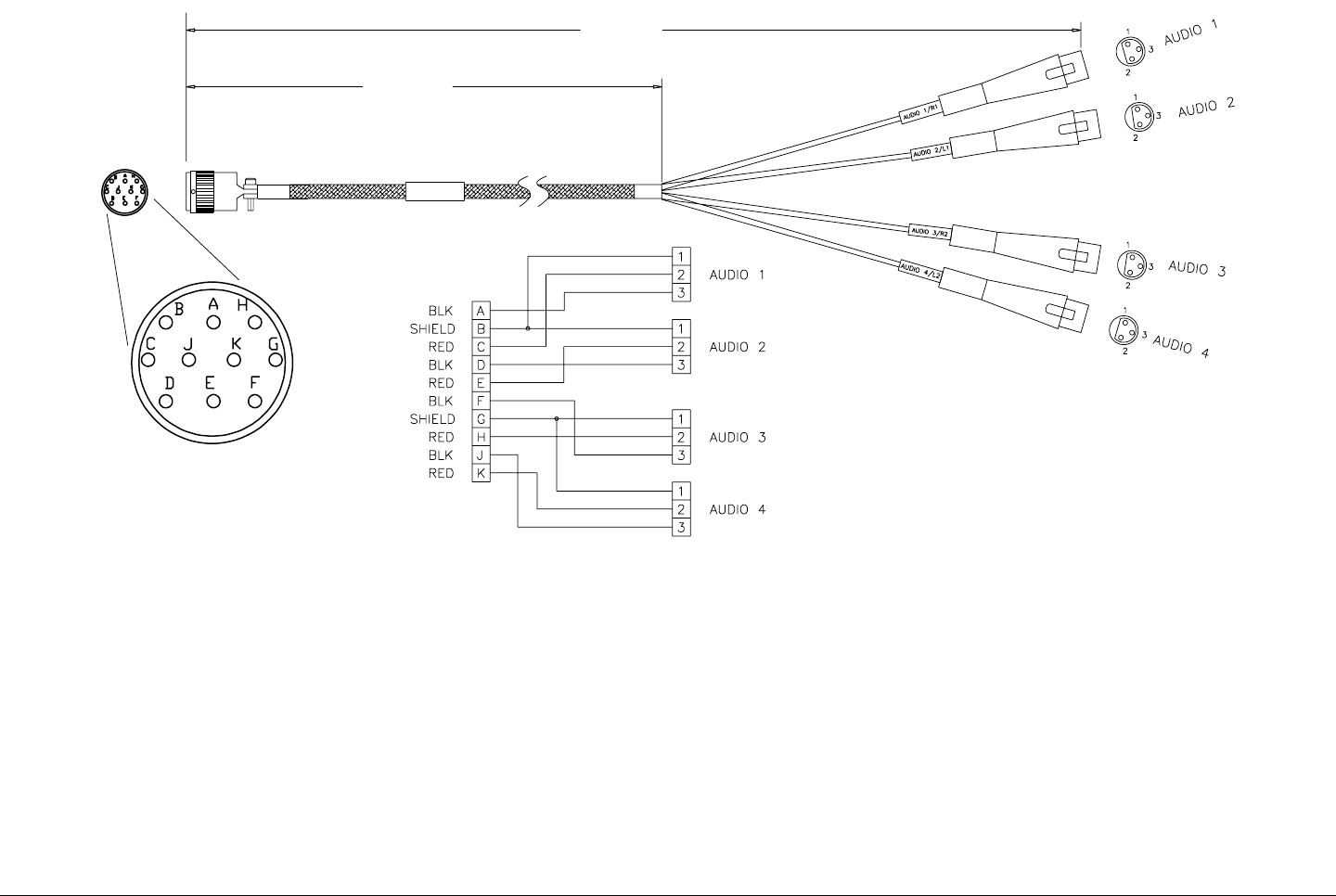
Installation 6-10PTX-PRO User and Technical Manual
Figure 6-10: Audio XLR Cable Assembly
22.00"
[55.88 cm]
38.00"
[96.52 cm]
Face
View
6.8.4 AES/EBU Audio Input
The PTX-PRO will only provide digital audio when operating in
digital mode.
In digital mode, the PTX-PRO receives a digital signal and routes
the data to the MPEG encoder and then to the COFDM
modulator. The PTX-PRO audio switching circuitry connects the
output of the MPEG encoder to the AUDIO connector.
When configured for digital audio output (AES/EBU), the MPEG
encoder provides two paired channels of digital data (+ and -), or
four individual channels. All four circuits are balanced inputs, with
each pair (+ and -) sharing one ground.
In digital mode, the audio channels are referred to as Audio A
and Audio B.
6.8.5 Video Connections
The PTX-PRO provides several video input and output options.
Video connections are made to the BNC SIGNAL INPUT or SDI/
ASI INPUT connectors located on the front panel of the PTX-

Installation 6-11PTX-PRO User and Technical Manual
PRO. Video input selections are made by selecting Presets
created using the Configurator software.
Video input options for the PTX-PRO are shown in Table 6-4.
6.9 Signal Connections
Details of the PTX-PRO signal connections are shown in Table
6-5.
Table 6-4: Video Input and Output Signal Options
Operation
Mode Signal Input Signal
Output Notes
MPEG/
COFDM IF
Out
NTSC/PAL
(525/625)
COFDM - RF Up-converted
Channeled RF
signal
SDI (525/625) COFDM - RF
ASI COFDM - RF
Ext IF In 70 MHz RF
6.10 Data Connections
The PTX-PRO contains an RS 232 data connector located on
the rear panel. The male DB-9 connector is used for the
following purposes:
• Radio programming using a PC
• Wayside data communication.
The PTX-PRO can be connected to a PC via a standard null
modem cable or it can be interfaced to a LAN for applications
such as remote monitoring and control.
Table 6-5: Signal Connections
Unit Function Connector Notes
PTX-PRO MONITOR
Connector
75 Ohm
BNC
Female
70 MHz signal output
monitoring connection.
SIGNAL
INPUT
Connector
75 Ohm
BNC
Female
Input may be NTSC 70
MHz IF or composite
video.
SDI/SD/
HD
Connector
75 Ohm
BNC
Female
HD/SD SDI external data
stream input.
SDI/ASI
INPUT
Connector
75 Ohm
BNC
Female
SDI/ASI external data
stream input.
RF Output
Connector
50 Ohm
Type N
Female
13 GHz RF output .
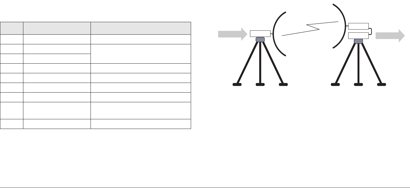
Installation 6-12PTX-PRO User and Technical Manual
6.10.1 PTX-PRO Programming
The RS-232 data connection is used when programming the
PTX-PRO using the Configurator software running on a
Microsoft Windows-based PC.
The PTX-PRO is configured to be a DTE device. If you need to
access the radio programming connections, a null modem cable
is used to connect the PTX-PRO to your PC. One cable is
supplied with each PTX-PRO ordered. Additional cables can be
purchased from MRC or from any computer or electronics store.
Programming connections are shown in Table 6-6.
6.10.2 Wayside Data
Overview The Wayside channel is a simplex data channel
transmitting data from the PTX-PRO to a receiver system. See
Figure 6-11. Data inputs to the PTX-PRO are provided via
Table 6-6: RS-232 Panel Connector
Pin Function Comments
1N/C
2 Receive Data Used for communication between
PTX-PRO and external computer.
3 Transmit Data
4N/C
5GND
6N/C
7 Transmit Data Wayside data
8 Receive Data
(Wayside)
Used to carry Wayside Data from
an external device.
9N/C
connections to the serial port through a Multipurpose Data Cable
provided by MRC.
Compatibility MRC has verified that the Wayside channel is
compatible with the following receivers:
• STRATA Receiver Unit (RXU) with MPEG decoding
• STRATA Receiver Control Unit (RCU) with MPEG
decoding.
• Tandberg Alteia IRD (Integrated Receiver Decoder)
Figure 6-11: Wayside Simplex Data Channel
Wayside Connections to the Serial Port Connecting the
Wayside channel to the serial port requires use of a Serial/
Wayside Multipurpose Data Cable as shown in Figure 6-12 on
page 6-13 and Figure 6-17 on page 6-16.
TX
RX
WAYSIDE WAYSIDE
Installation 6-13PTX-PRO User and Technical Manual
Figure 6-12: Wayside and Serial Interface Connections
The cable connects to the RS 232 connector on the PTX-PRO
and has connections for both the Wayside channel and the PC or
laptop required for use with the MRC Radio Configurator
(Configurator) software.
Wayside Data connections are shown in Table 6-6 on page 6-12
and in Figure 6-17 on page 6-16.
Wayside Transmitter and Receiver Connections Data
connections on the transmit end of the Wayside channel for the
RS 232 serial port connector on the PTX-PRO are shown in
Figure 6-17 on page 6-16.
Data connections on the Receive end of the Wayside channel for
the RS 232 serial port connector on the PTX-PRO are shown in
Figure 6-17 on page 6-16. Both serial and Wayside connections
are shown.
6.10.3 Panel Data Connectors
The pinout of the RS 232 serial port DB-9 connector is shown in
Figure 6-13 and Table 6-6 on page 6-12.
TX or RX
RS-232 Wayside
Data Channel
Signal (i.e.,
GPS Data)
Multipurpose
Data Cable
RS-232
Serial
Connection to
PC or Laptop
Figure 6-13: RS-232 Panel Connector
6.10.4 Multipurpose Data Cable
In order to access both radio and Wayside data, you need to use
a Multipurpose Data Cable. The cable and wiring diagram are
shown in Figure 6-17 on page 6-16. If necessary, the
Multipurpose Data Cable may be ordered from MRC.
The Multipurpose Data Cable contains two DB-9 female
connectors and one DB-9 male connector. The Multipurpose
Data Cable contains band markers indicating connections to
HOST, WAYSIDE, and RS-232 connectors. The Multipurpose
Data Cable DB-9 female RS-232 connector is connected to the
PTX-PRO RS 232 connector.
The HOST DB-9 male connector is configured as a Data
Terminal Equipment (DTE) device connector for connection to a
PC or laptop PC. When connected to a DTE device, a null
modem cable must be connected between the DTE device and
the Multipurpose Data Cable DB-9 HOST male connector. If
connected to a Data Communications Equipment (DCE) device,
a null modem cable cannot be used, but a straight pin-to-pin
extension cable will be required.
The WAYSIDE DB-9 female connector is configured as a DCE
device connector for connection to a modem, GPS, etc. When
1 2 3 4 5
6 7 8 9
DB-9 Male -
Front View
Installation 6-14PTX-PRO User and Technical Manual
connected to a DCE device, a null modem cable must be
connected between the DCE device and the Multipurpose Data
Cable DB-9 female WAYSIDE connector. If connected to a DTE
device, a null modem cable cannot be used, but a straight pin-to-
pin extension cable will be required.
Null modem cables may be obtained from MRC or any computer
or electronics store.
6.10.5 Networking
The RS 232 connector on the PTX-PRO can also be connected
to a network if desired. This allows both monitoring and
programming the PTX-PRO from a remote location.
To connect the PTX-PRO to a network, you will need the items
described below. See Figure 6-14.
Figure 6-14: Network Interconnection
• Device Server
There are several types on the market. Also called Serial-
to-Ethernet converters, they take serial RS-232 data and
convert it to the format needed for an Ethernet network.
One type MRC has used with success is the Lantronix
UDS-10. It accepts data via a DB-25 connector, and
PTX-PRO TX
System
UDS-10 Device
Server (or
Equivalent)
Interface
Cable
Ethernet LAN
connects to the network via an RJ-45 connector. See
Figure 6-15.
• Interface Cable
This cable is needed to connect to the PTX-PRO data
connector (DB-9) on one end and connect to the device
server on the other (a DB-25 connector in the case of the
UDS-10).
This is a custom cable which you will have to fabricate.
See Figure 6-16 on page 6-15 for the connections on the
PTX-PRO end.
Figure 6-15: Lantronix UDS-10 Device Server
Installation 6-15PTX-PRO User and Technical Manual
Figure 6-16: Network Interface Cable
2
3
5
7
8
RD
TD
SG
SG
TD
RD
Radio
Data
Wayside
Data
Signal Ground
Receive Data
Transmit Data
Wayside Data to External
Device
Wayside Data from External
Device (Not Used)
Transmit Wayside
Data
Receive Wayside
Data
To PTX-PRO RS-232
Connector DB-9 (Male)
Installation 6-16PTX-PRO User and Technical Manual
Figure 6-17: Multipurpose Radio and Wayside Data Cable
9
9
5
5
1
1
6
6
1
1
6
6
9
9
5
5
5
5
1
1
6
6
9
9
RED
RED
WHT
WHT
5
5
7
7
6
6
4
4
3
3
2
2
1
1
8
8
9
9
9
9
8
8
1
1
2
2
3
3
4
4
6
6
7
7
5
5
9
9
8
8
1
1
2
2
3
3
4
4
6
6
7
7
5
5
WHT
WHT
RED
RED
BLK
BLK
RADIO (M)
RADIO (M)
WAYSIDE (F)
WAYSIDE (F)
RADIO (M)
RADIO (M)
WAYSIDE (F)
WAYSIDE (F)
RADIO/WAYSIDE
RADIO/WAYSIDE
(F)
(F)
RADIO/
RADIO/
WAYSIDE (F)
WAYSIDE (F)
6.11 Powering Up
When the wiring and mounting are completed, it is time to power
up the PTX-PRO. As good practice, you should make a final
check before power is applied.
6.11.1 Checks before power-up
Here are your final pre-power-up checks:
• Double check to be sure all the cables are connected to
the correct connectors.
• Make sure the connections are all fully mated and locked.
CAUTION Be sure the power being supplied matches
the power required by the equipment.
6.11.2 Initial power-up
Now you are ready to apply power:
1. Verify the power cable is properly connected to the front
panel power connector.
Installation 6-17PTX-PRO User and Technical Manual
2. Verify all front and rear panel cables and connectors
have been properly connected. Connect the power
cable to AC or DC power of the correct voltage and
polarity. Verify the power source is turned on.
3. Set the PWR switch to I (on).
4. The normal power-up sequence is as follows:
-The PWR LED above the PWR switch should
illuminate and should quickly change colors from red,
to green, to amber, to green, and should remain green.
- The alphanumeric display should light up and quickly
display a self-test screen, then the version of the
firmware, and finally the Main Screen.
Some typical screens are shown in Figure 6-18. Exact
screens displayed will vary.
- The PTX-PRO will typically power up using the last
settings in use when power was turned off.
If the PTX-PRO does not power up normally, refer to
the “Troubleshooting” Chapter on page 4-1.
Figure 6-18: Typical PTX-PRO Power Up Screen
5. If everything appears to be normal, test the
performance of your PTX-PRO by setting up a link and
PTX-PRO
V X.X.X
Preset #1
0.00W
Firmware
Version
Main Screen
transmitting and receiving video and audio.
If you have any problems, refer to the “Troubleshooting” Chapter
on page 4-1 to determine the cause.
6.12 Configurator Software Installation
The steps required to install the MRC Radio Configurator
software on your PC is contained in the following steps.
6.12.1 PC Requirements
The MRC Radio Configurator software (Configurator) is
designed to run on Microsoft Windows -based PCs that meet the
requirements shown in Table 6-7.
• Microsoft Windows XP Operating System with SP2
• 500 MB of free hard disk space
• CD-ROM drive
• Internet Explorer 4.01 SP1 or later
• One RS-232 I/O port configured as COM 1 thru COM 9.
6.12.2 Installing Configurator Software
Before using the MRC Radio Configurator, it must be installed on
your PC. To install the Configurator, perform the following steps.
Table 6-7: PC Requirements
Minimum Maximum
Processor Speed 400 MHz 1 GHz
RAM 96 MB 256 MB
Screen Resolution 800x600 1024x768
Installation 6-18PTX-PRO User and Technical Manual
Note If any version of the MRC Radio Configurator is
already installed, you must uninstall it before
attempting to install a new version.
Use the “Add/Remove Programs” feature in the
Microsoft Windows Control Panel to do this.
1. Locate the CD that was provided with your PTX-PRO.
2. Insert the CD into your computer CD drive.
3. Using the My Computer icon on your PC (or any other
method), navigate to that CD drive and display the CD
directory on your screen.
4. Open the CD, select the MRC Radio Configurator, and
observe the Setup Wizard is displayed. See Figure 6-
19.
Figure 6-19: Setup Wizard
5. Select the Next option button and observe the Select
Installation Folder window is displayed. See
Figure 6-20.
Figure 6-20: Select Installation Folder Window
6. Select the folder in which you wish to save the
Configurator software using the Browse option button
or accept the default folder, select the Next option
button, and observe the Confirm Installation window
is displayed. See Figure 6-21 on page 6-19.
Installation 6-19PTX-PRO User and Technical Manual
Figure 6-21: Confirm Installation Window
7. Select the Next option button and observe the
Installing MRC Radio Configurator window is
displayed. See Figure 6-22.
Figure 6-22: Installing MRC Radio Configurator Window
8. When the software installation is complete, observe
the Installation Complete window is displayed. See
Figure 6-23.
Figure 6-23: Installation Complete Window
9. Select the Close option button and observe the MRC
Radio Configurator icon is displayed on your
desktop. See Figure 6-24.
Figure 6-24: MRC Radio Configurator Icon - Typical

Installation 6-20PTX-PRO User and Technical Manual
6.13 Product Modifications
The product you purchased has been carefully designed and
tested, and is warranted to meet specifications when connected
and operated as described in this manual.
Note If you modify a product without authorization from
MRC, you will void the warranty.

7
Replacement Parts 7-1PTX-PRO User and Technical Manual
Replacement Parts
7.1 Chapter Overview
This chapter describes which replacement parts are available for
the PTX-PRO 13 GHz Transmitter (PTX-PRO).
Since there are no supported field repairs on the PTX-PRO.
The only parts available are external cables and mounting
hardware.
7.2 External Cables
The external cables and connectors for the PTX-PRO are listed
in Table 7-1. If you need something that is not listed, ask your
Sales Representative or consult the factory.
Table 7-1: PTX-PRO Cables and Connectors
Description Comments
AC Power Cable (120
VAC)
Connects AC power to the PTX-PRO.
Connectors on both ends.
AC Power Cable (240
VAC)
Connects AC power to the PTX-PRO.
Connectors on one end only.
DC Power Cable (+11.0 to
+36.0 VDC)
Connects DC power to the PTX-PRO.
Connector on one end only.
Audio Input Cable Provides input to PTX-PRO AUDIO 1
and 2 connectors from two XLR
connectors. See “Audio Connections”
on page 6-8.
7.3 Mounting Hardware
The mounting hardware for the PTX-PRO is listed in Table 7-2. If
you need something that is not listed, ask your Sales
Representative or consult the factory.
Null Modem Cable Connects PTX-PRO RS-232
connector to PC RS-232 connector.
For programming and monitoring data
only. See ”Data Connections” on
page 6-11.
Audio Input Connector Connects to PTX-PRO AUDIO 3 & 4
connector for Audio 3 and 4 inputs.
See ”Data Connections” on page 6-11.
Multipurpose Data Cable Connects to PTX-PRO RS 232
connector to monitor Wayside and
Radio data.
RF Coaxial Cable Connects PTX-PRO RF output
connector to antenna.
Power Input Connector Connector only - Mates with PTX-
PRO PWR connector.
Audio Input XLR
Connector
Connector only - Mates with PTX-
PRO AUDIO 1 or 2 connectors.
Table 7-2: PTX-PRO Mounting Hardware
Description Comments
Antenna Lock Plate Attaches an MRC antenna directly to
PTX-PRO RF output connector.
Table 7-1: PTX-PRO Cables and Connectors (Continued)
Description Comments
Replacement Parts 7-2PTX-PRO User and Technical Manual
7.4 Power Fuses
The PTX-PRO configurations operate on the following external
AC or DC power sources:
• 90 to 264 VAC, 50/60 Hz
• +11.0 to +36.0 VDC
Power fuses for the AC and DC configurations of the PTX-PRO
are located on the rear panel of the unit. See Figure 7-1 .
Figure 7-1: AC and DC Power Fuse Locations
Fuse ratings for the AC and DC power sources are shown in
Table 7-3.
Quick Release Provides quick release mounting
capabilities of the PTX-PRO units on
an MRC tripod
Table 7-2: PTX-PRO Mounting Hardware (Continued)
Description Comments
AC Fuse DC Fuse
7.5 Supported Repairs
The PTX-PRO is designed to be compact, rugged, and reliable.
The PTX-PRO requires specialized test equipment to calibrate
amplitude and frequency characteristics after repair. In addition,
sealing the PTX-PRO enclosure after repair requires exacting
techniques and special fixtures to ensure weather resistance of
the units.
There are NO supported field repairs for the PTX-PRO .
Return the entire unit for factory repair.
If you attempt field repair, you risk damaging your
equipment. If your equipment is under warranty, you may also
affect your warranty coverage.
Table 7-3: Fuse Ratings
Operating Voltage Fuse Rating
90 to 264 VAC, 50/60 Hz 2.0A, 250V AGC, Slow Blow
+11.0 to +36.0 VDC 15.0A, 250V, Slow Blow
8
Theory of Operation 8-1PTX-PRO User and Technical Manual
Theory of Operation
8.1 Chapter Overview
This chapter provides technical details about the design and
functioning of the PTX-PRO 13 GHz Transmitter (PTX-PRO).
This chapter is intended to complement information contained in
the “Product Description” Chapter on page 2-1.
The descriptions in this chapter assume you are already familiar
with the information contained in Chapter 2. We recommend
that you review Chapter 2 before beginning to read this one.
Here are the topics covered:
8.2 System Architecture
The PTX-PRO is designed around a flexible, modular
architecture. The overall PTX-PRO system architecture for a
PTX-PRO is shown in Figure 8-1.
The PTX-PRO is a versatile portable transmitter designed to
accept an IF 70 MHz input signal or composite video signal,
audio signals, or SD/HD SDI signals or ASI/SDI signals from
external sources and to provide a 13 GHz microwave signal
output.
Topic Page
System Architecture 8-1
System Theory of Operation 8-2
Command and Control Power Supply 8-2
MPEG/COFDM Encoder/Modulator Module 8-2
Figure 8-1: PTX-PRO System Architecture
All configurations are available with either NTSC or PAL system
modulation.
PTX-PRO key features are:
• RF output high/low power selection for 13 GHz operation
• System modulation scheme:
Digital: COFDM or LMS-T
• COFDM Modulation:
Selectable 6, 7, or 8 MHz bandwidth
QPSK, 16 QAM, or 64 QAM
• COFDM Modulation with selectable Guard Interval
technology (1/4, 1/8, 1/16/ or 1/32)
• Forward Error Correction (FEC) (1/2, 3/5, 5/6, or 7/8)
• MPEG encoding with SD and optional HD video solution
technologies
• Front panel local control
• Wide choice of antennas.
PTX-PRO
TX System
RS-232
120/240 VAC, 50/60
Hz or +11.0 to +36.0
VDC
AUDIO/
AES/EBU
RF OUT
MONITOR
SDI/SD/
HD
SD I/ASI
IN PU T
SIGNAL
IN PU T

Theory of Operation 8-2PTX-PRO User and Technical Manual
All PTX-PRO configurations are available with Standard
Definition (SD) or SD and optional High Definition (HD) video
technologies.
The PTX-PRO can accept a wide variety of signal formats and
includes an RF up-converter for use in transporting signals over
a microwave link. The PTX-PRO also contains an MPEG/
COFDM module.
The PTX-PRO contains a universal power supply and can
operate on 90 to 264 VAC, 50/60 Hz or +11.0 to +36.0 VDC.
8.3 System Theory of Operation
The PTX-PRO is comprised of the following primary
components:
• Command and control universal power supply module
• MPEG encoder/COFDM modulator module
See Figure 8-2 on page 8-3 for a block diagram of the 13 GHz
PTX-PRO.
The PTX-PRO also contains the IF/RF module which accepts
either a 70 MHz COFDM or external 70 MHz input signal and up-
converts these signals to the 13 GHz RF band. The PTX-PRO
can therefore serve as a standalone digital video microwave
transmission system.
The RF frequency synthesizer circuit included in the IF/RF
module, along with the command and control module, provide
the means to channelize RF video and audio signals in the 13
GHz RF band. Standard U.S. FCC band plans, as well as
custom channel plans, may be accommodated using the MRC
Radio Configurator (Configurator), when the Configurator
software is connected to the PTX-PRO.
8.3.1 Command and Control Power Supply
The PTX-PRO command and control power supply modules
contain external and internal communications circuitry, as well as
supplying necessary system voltages.
The PTX-PRO power supply accepts a wide range of DC input
voltages (+11.0 to +36.0 VDC) or 90 to 264 VAC, 50/60 Hz. The
supply converts the input voltage to the DC voltages required by
the rest of the PTX-PRO circuits and distributes the appropriate
output voltages to the various circuits.
The on-board microprocessor manages the system configuration
and operation of all modules to which it is connected, e.g.,
MPEG/COFDM, IF/RF modules, etc.
This ensures that the PTX-PRO can permit switching modes of
operation, change system Presets, etc. Therefore, system
control may be accomplished using front panel control or remote
control.
8.3.2 MPEG/COFDM Encoder/Modulator Module
The MPEG/COFDM module is the heart of the PTX-PRO digital
mode circuitry. This circuit may be configured to accept a wide
range of digital or analog video and audio signal inputs and
provide COFDM IF (70 MHz) video signal outputs.
The various signal inputs and outputs are connected through the
PTX-PRO combiner circuit where they are switched under
software control.
Theory of Operation 8-3PTX-PRO User and Technical Manual
Figure 8-2: Standalone 13 GHz PTX-PRO Block Diagram
AC to DC
Converter
DC Power
Distribution and
Control
AC
Input
DC
Input
AC
Fuse
DC
Fuse
Front Panel
RS232
Baseband
Combiner
HD Encoder/
Modulator
Up Converter
13 GHz Mixer 13 GHz
Power
Amplifier
Band Pass
Filter
70 MHz
MONITOR
SIGNAL
INPUT
SDI/ASI
INPUT
SDI/SD/
HD
ASI
Output
13 GHz
RF Output
AUDIO 1
AUDIO 2
X4
RF
IF
LO
AUDIO 3 & 4/
AES/EBU

Theory of Operation 8-4PTX-PRO User and Technical Manual

Index Index-1PTX-PRO User and Technical Manual
Index
A
About This Manual . . . . . . . . . . . . . . . . . . . . . . . . . . . Notices-i
Advanced Operation . . . . . . . . . . . . . . . . . . . . . . . . . . . . . . .5-1
Alphanumeric display . . . . . . . . . . . . . . . . . . . . . . . . . . . . . .3-2
Audio Connections . . . . . . . . . . . . . . . . . . . . . . . . . . . . . . . .6-8
AES/EBU Audio Input . . . . . . . . . . . . . . . . . . . . . . . .6-10
MPEG Audio Input . . . . . . . . . . . . . . . . . . . . . . . . . . .6-9
Panel Connections . . . . . . . . . . . . . . . . . . . . . . . . . . .6-8
C
Calling for Service . . . . . . . . . . . . . . . . . . . . . . . . . . . . . 1-1, 7-1
CAUTION
Electrostatic Discharge . . . . . . . . . . . . . . . . . . Notices-iv
CAUTIONS . . . . . . . . . . . . . . . . . . . . . . . . . . . . . . . . Notices-iv
Certification
ISO 90012000 . . . . . . . . . . . . . . . . . . . . . . . . . . Notices-i
COFDM . . . . . . . . . . . . . . . . . . . . . . . . . . . . . . . . . . . . . 2-1, 2-3
COFDM Modulation . . . . . . . . . . . . . . . . . . . . . . . . . . . . . . . .9-1
Configurator
Configurator Error Messages . . . . . . . . . . . . . . . . . . .4-7
Graphical User Interface (GUI) . . . . . . . . . . . . . . . . . .5-3
installing the Configurator . . . . . . . . . . . . . . . . . . . . .6-18
PC requirements . . . . . . . . . . . . . . . . . . . . . . . . . . . .6-18
troubleshooting . . . . . . . . . . . . . . . . . . . . . . . . . . . . . .4-7
Configurator software
Create a configuration off-line . . . . . . . . . . . . . . . . . . .5-3
Create a configuration online . . . . . . . . . . . . . . . . . . .5-3
how to use . . . . . . . . . . . . . . . . . . . . . . . . . . . . . . . . . .5-1
Load a configuration from the PTX-PRO . . . . . . . . . .5-3
Load an existing configuration from a file . . . . . . . . . .5-3
Load and modify individual configuration pages . . . . .5-3
load configuration file into the PTX-PRO . . . . . . . . . . 5-3
system rules . . . . . . . . . . . . . . . . . . . . . . . . . . . . . . . 5-2
Conventions . . . . . . . . . . . . . . . . . . . . . . . . . . . . . . . . Notices-iv
Copyright . . . . . . . . . . . . . . . . . . . . . . . . . . . . . . . . . . . Notices-i
Creating a Configuration . . . . . . . . . . . . . . . . . . . . . . . . . . . 5-3
Customer-created channel plans . . . . . . . . . . . . . . . . . . 2-1, 2-3
D
Data Connections . . . . . . . . . . . . . . . . . . . . . . . . . . . . . . . . 6-11
Multipurpose Data Cable . . . . . . . . . . . . . . . . . . . . . 6-13
Networking . . . . . . . . . . . . . . . . . . . . . . . . . . . . . . . . 6-14
Radio Programming . . . . . . . . . . . . . . . . . . . . . . . . . 6-12
Wayside Data . . . . . . . . . . . . . . . . . . . . . . . . . . . . . 6-12
Digital Video Broadcasting . . . . . . . . . . . . . . . . . . . . . . . . . . 2-1
E
Electronic News Gathering . . . . . . . . . . . . . . . . . . . . . . . . . . 2-1
E-mail
Feedback . . . . . . . . . . . . . . . . . . . . . . . . . . . . . . . . . . 1-2
Technical Support team . . . . . . . . . . . . . . . . . . . . . . . 1-2
External 70 MHz input . . . . . . . . . . . . . . . . . . . . . . . . . .2-1, 2-3
F
Feedback . . . . . . . . . . . . . . . . . . . . . . . . . . . . . . . . . . . . . . . 1-2
FMT IF . . . . . . . . . . . . . . . . . . . . . . . . . . . . . . . . . . . . . . 2-1, 2-3
For Whom It’s Written . . . . . . . . . . . . . . . . . . . . . . . . . . . . . 1-1
Frequently Performed Tasks
Powering the PTX-PRO Transmitter System . . . . . . 3-5
Preparing for Operation
Portable Deployment . . . . . . . . . . . . . . . . . . . . . . 6-2
Fuse . . . . . . . . . . . . . . . . . . . . . . . . . . . . . . . . . . . . . . Notices-iv
G
General System Problems . . . . . . . . . . . . . . . . . . . . . . . . . . 4-7
Ground
Earth . . . . . . . . . . . . . . . . . . . . . . . . . . . . . . . . Notices-iv

Index Index-2PTX-PRO User and Technical Manual
Frame or Chassis . . . . . . . . . . . . . . . . . . . . . . Notices-iv
Protective Earth . . . . . . . . . . . . . . . . . . . . . . . Notices-iv
Grounding . . . . . . . . . . . . . . . . . . . . . . . . . . . . . . . . . . . . . . .6-8
H
High Definition . . . . . . . . . . . . . . . . . . . . . . . . . . . . . . . . . . . .2-2
HPU Indicators and Connectors . . . . . . . . . . . . . . . . . . . . . .3-5
I
Initial
Inspection . . . . . . . . . . . . . . . . . . . . . . . . . . . . . . . . . .6-1
Initial Inspection . . . . . . . . . . . . . . . . . . . . . . . . . . . . . . . . . . .6-1
Inspection
Initial . . . . . . . . . . . . . . . . . . . . . . . . . . . . . . . . . . . . . .6-1
Installation . . . . . . . . . . . . . . . . . . . . . . . . . . . . . . . . . . . . . . .6-1
Powering Up . . . . . . . . . . . . . . . . . . . . . . . . . . . . . . .6-16
M
Major Alarm . . . . . . . . . . . . . . . . . . . . . . . . . . . . . . . . . . . . . .3-3
Monitoring
Using the Monitor Screens in Ext IF Input Mode . . . .3-7
Mounting and Cabling . . . . . . . . . . . . . . . . . . . . . . . . . . . . . .6-2
MPEG Encoding . . . . . . . . . . . . . . . . . . . . . . . . . . . . . . . . . .9-1
MPEG/CODFM module . . . . . . . . . . . . . . . . . . . . . . . . . 2-1, 2-3
MRC Customer Service . . . . . . . . . . . . . . . . . . . . . . . . . . . . .1-1
Business Hours . . . . . . . . . . . . . . . . . . . . . . . . . . . . . .1-1
Telephone . . . . . . . . . . . . . . . . . . . . . . . . . . . . . . . . . .1-1
MRC Technical Support . . . . . . . . . . . . . . . . . . . . . . . . . . . .1-1
Business Hours . . . . . . . . . . . . . . . . . . . . . . . . . . . . . .1-1
E-mail . . . . . . . . . . . . . . . . . . . . . . . . . . . . . . . . . 1-1, 7-1
Telephone . . . . . . . . . . . . . . . . . . . . . . . . . . . . . . . . . .1-1
N
Network
Lantronix UDS-10 . . . . . . . . . . . . . . . . . . . . . . . . . . .6-14
Notes . . . . . . . . . . . . . . . . . . . . . . . . . . . . . . . . . . . . . Notices-iv
O
On-Line Viewing . . . . . . . . . . . . . . . . . . . . . . . . . . . . . Notices-iv
Operational Problems
General System . . . . . . . . . . . . . . . . . . . . . . . . . . . . . 4-7
Video . . . . . . . . . . . . . . . . . . . . . . . . . . . . . . . . . . . . . 4-6
Ordering Documentation . . . . . . . . . . . . . . . . . . . . . . . . . . . 1-1
Outside Broadcast . . . . . . . . . . . . . . . . . . . . . . . . . . . . . . . . 2-1
P
Panel Data Connectors . . . . . . . . . . . . . . . . . . . . . . . . . . . 6-13
Portable Deployment
Dovetail Adapter Plates . . . . . . . . . . . . . . . . . . . . . . . 6-3
Quick Release Mount . . . . . . . . . . . . . . . . . . . . . . . . 3-5
Power Cable Assemblies . . . . . . . . . . . . . . . . . . . . . . . . . . . 6-6
Power Connections . . . . . . . . . . . . . . . . . . . . . . . . . . . . . . . 6-5
Additional Powering Notes . . . . . . . . . . . . . . . . . . . . 6-7
Power Supply and Distribution . . . . . . . . . . . . . . . . . . . . . . . 6-5
Presets . . . . . . . . . . . . . . . . . . . . . . . . . . . . . . . . . . . . . . . . . 2-3
Audio and video . . . . . . . . . . . . . . . . . . . . . . . . . . . . . 2-3
Frequency . . . . . . . . . . . . . . . . . . . . . . . . . . . . . . . . . 2-3
Modulation . . . . . . . . . . . . . . . . . . . . . . . . . . . . . . . . . 2-3
product modifications . . . . . . . . . . . . . . . . . . . . . . . . . . . . . 6-20
Proprietary Material . . . . . . . . . . . . . . . . . . . . . . . . . . . Notices-i
PTX-PRO
Configurator software . . . . . . . . . . . . . . . . . . . . . . . . 2-3
Controls, indicators, and connectors . . . . . . . . . . . . . 3-1
AC fuse . . . . . . . . . . . . . . . . . . . . . . . . . . . . . . . . 3-5
AC/DC power connector . . . . . . . . . . . . . . . . . . . 3-4
CHANNEL selector switch . . . . . . . . . . . . . . . . . . 3-2
Control Switch . . . . . . . . . . . . . . . . . . . . . . . . . . . 3-3
DC fuse . . . . . . . . . . . . . . . . . . . . . . . . . . . . . . . . 3-5
DC ON COAX switch . . . . . . . . . . . . . . . . . . . . . . 3-5
MONITOR connector . . . . . . . . . . . . . . . . . . . . . . 3-2
OFFSET switch . . . . . . . . . . . . . . . . . . . . . . . . . . 3-2
PWR LED . . . . . . . . . . . . . . . . . . . . . . . . . . . . . . . 3-3

Index Index-3PTX-PRO User and Technical Manual
PWR switch . . . . . . . . . . . . . . . . . . . . . . . . . . . . . .3-4
RF output connector . . . . . . . . . . . . . . . . . . . . . . .3-4
RS 232 connector . . . . . . . . . . . . . . . . . . . . . . . . .3-5
SDI/ASI INPUT connector . . . . . . . . . . . . . . . . . . .3-3
SDI/HD/SD connector . . . . . . . . . . . . . . . . . . . . . .3-3
SIGNAL INPUT connector . . . . . . . . . . . . . . . . . . .3-2
XLR AUDIO connector . . . . . . . . . . . . . . . . . . . . .3-2
XMIT LED . . . . . . . . . . . . . . . . . . . . . . . . . . . . . . .3-4
Installation
AC or DC power cable fabrication . . . . . . . . . . . . .6-6
AC Power Cable Assemblies . . . . . . . . . . . . . . . . .6-6
audio inputs . . . . . . . . . . . . . . . . . . . . . . . . . . . . . .6-8
damage in shipment . . . . . . . . . . . . . . . . . . . . . . .6-1
DC Power Cable Assembly . . . . . . . . . . . . . . . . . .6-6
grounding . . . . . . . . . . . . . . . . . . . . . . . . . . . . . . . .6-8
Initial inspection . . . . . . . . . . . . . . . . . . . . . . . . . . .6-1
Multipurpose Data Cable . . . . . . . . . . . . . . . . . . .6-13
networking . . . . . . . . . . . . . . . . . . . . . . . . . . . . . .6-14
portable deployment . . . . . . . . . . . . . . . . . . . . . . .6-2
Power cable assemblies . . . . . . . . . . . . . . . . . . . .6-6
power requirements . . . . . . . . . . . . . . . . . . . . . . . .6-5
power up . . . . . . . . . . . . . . . . . . . . . . . . . . . . . . .6-16
RS 232 data connections . . . . . . . . . . . . . . . . . .6-11
signal connections . . . . . . . . . . . . . . . . . . . . . . . .6-11
Unpacking . . . . . . . . . . . . . . . . . . . . . . . . . . . . . . .6-1
video input and output connections . . . . . . . . . . .6-10
Wayside connections . . . . . . . . . . . . . . . . . . . . . .6-12
power up and power . . . . . . . . . . . . . . . . . . . . . . . . . .3-5
repairs . . . . . . . . . . . . . . . . . . . . . . . . . . . . . . . . . . . . .7-1
replacement parts . . . . . . . . . . . . . . . . . . . . . . . . . . . .8-1
external cables and connectors . . . . . . . . . . . . . . .8-1
mounting hardware . . . . . . . . . . . . . . . . . . . . . . . .8-1
Power fuses . . . . . . . . . . . . . . . . . . . . . . . . . . . . . .8-2
PTX-PRO and HPU
supported field repairs . . . . . . . . . . . . . . . . . . . . . . . .8-1
PTX-PRO Configuration Utility
Creating a Configuration . . . . . . . . . . . . . . . . . . . . . . 5-3
PWR LED . . . . . . . . . . . . . . . . . . . . . . . . . . . . . . . . . . . . . . . 3-3
Q
Quality Certification . . . . . . . . . . . . . . . . . . . . . . . . . . . Notices-i
R
Related Documents . . . . . . . . . . . . . . . . . . . . . . . . . . . . . . . 1-1
Repair . . . . . . . . . . . . . . . . . . . . . . . . . . . . . . . . . . . . . . . . . . 7-1
Replacement Parts . . . . . . . . . . . . . . . . . . . . . . . . . . . . . . . . 8-1
External Cables . . . . . . . . . . . . . . . . . . . . . . . . . . . . . 8-1
Mounting Hardware . . . . . . . . . . . . . . . . . . . . . . . . . . 8-1
S
Settings . . . . . . . . . . . . . . . . . . . . . . . . . . . . . . . . . . . . . . . . 5-1
Configurator software . . . . . . . . . . . . . . . . . . . . . . . . 3-1
front panel control switches . . . . . . . . . . . . . . . . . . . . 3-1
Signal Connections . . . . . . . . . . . . . . . . . . . . . . . . . . . . . . 6-11
Standard Definition . . . . . . . . . . . . . . . . . . . . . . . . . . . . . . . . 2-2
Supported field repairs . . . . . . . . . . . . . . . . . . . . . . . . . . . . . 7-1
PTX-PRO . . . . . . . . . . . . . . . . . . . . . . . . . . . . . . . . . . 7-1
Supported Repairs . . . . . . . . . . . . . . . . . . . . . . . . . . . . . 1-2, 7-1
Symbols Used . . . . . . . . . . . . . . . . . . . . . . . . . . . . . . Notices-iv
System Configuration . . . . . . . . . . . . . . . . . . . . . . . . . . . . . . 2-3
System Description
Key features . . . . . . . . . . . . . . . . . . . . . . . . . . . . . . . 9-1
PTX-PRO Transmitter System . . . . . . . . . . . . . . . . . 2-1
System Operation . . . . . . . . . . . . . . . . . . . . . . . . . . . . . . . . 2-3
System Problems . . . . . . . . . . . . . . . . . . . . . . . . . . . . . . . . . 4-7
System Rules . . . . . . . . . . . . . . . . . . . . . . . . . . . . . . . . . . . . 5-2
T
Technical Support . . . . . . . . . . . . . . . . . . . . . . . . . . . . . 1-1, 7-1
Tell Us What You Think . . . . . . . . . . . . . . . . . . . . . . . . . . . . 1-2
Theory of Operation . . . . . . . . . . . . . . . . . . . . . . . . . . . . . . . 9-1

Index Index-4PTX-PRO User and Technical Manual
Command and Control Power Supply . . . . . . . . . . . . .9-2
MPEG/COFDM Encoder/Modulator Module . . . . . . . .9-2
System Architecture . . . . . . . . . . . . . . . . . . . . . . . . . .9-1
Technical details . . . . . . . . . . . . . . . . . . . . . . . . . . . . .9-1
Troubleshooting . . . . . . . . . . . . . . . . . . . . . . . . . . . . . . . . . . .4-1
Error Status . . . . . . . . . . . . . . . . . . . . . . . . . . . . . . . . .4-3
Primary Error Code . . . . . . . . . . . . . . . . . . . . . . . . . . .4-3
TX Audio and Video Connections . . . . . . . . . . . . . . . . . . . .6-10
U
Unpacking . . . . . . . . . . . . . . . . . . . . . . . . . . . . . . . . . . . 6-1, 6-2
V
Video input options . . . . . . . . . . . . . . . . . . . . . . . . . . . . . . .6-11
Video Problems . . . . . . . . . . . . . . . . . . . . . . . . . . . . . . . . . . .4-6
W
WARNING
General . . . . . . . . . . . . . . . . . . . . . . . . . . . . . . Notices-iv
Risk of Electric Shock . . . . . . . . . . . . . . . . . . . Notices-iv
WARNINGS . . . . . . . . . . . . . . . . . . . . . . . . . . . . . . . . Notices-iv
Wayside Data
Overview . . . . . . . . . . . . . . . . . . . . . . . . . . . . . . . . . .6-12
Wayside Connections to the Serial Port . . . . . . . . . .6-12
WEEE . . . . . . . . . . . . . . . . . . . . . . . . . . . . . . . . . . . . Notices-iv