Microwave Radio Communications PTX270AD PTX-PRO Transmitter User Manual PTX PRO User and Tech
Microwave Radio Communications LLC PTX-PRO Transmitter PTX PRO User and Tech
UserManual.wiki
>
Microwave Radio Communications
>
PTX270AD User Manual
Manual
Navigation menu
Upload a User Manual
Namespaces
Wiki Guide
HTML
PDF
Info
Views
User Manual
Discussion / Help
Navigation

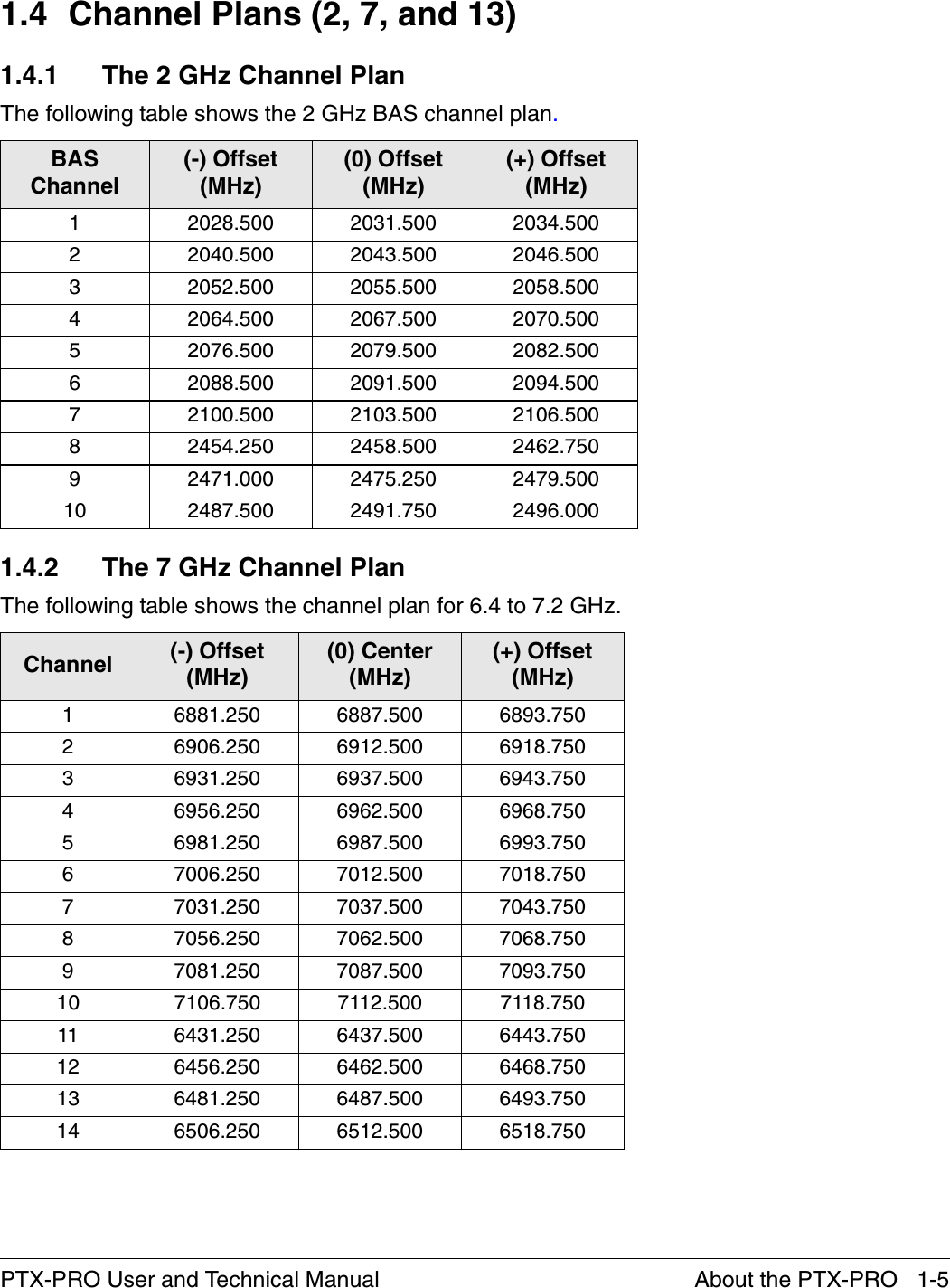
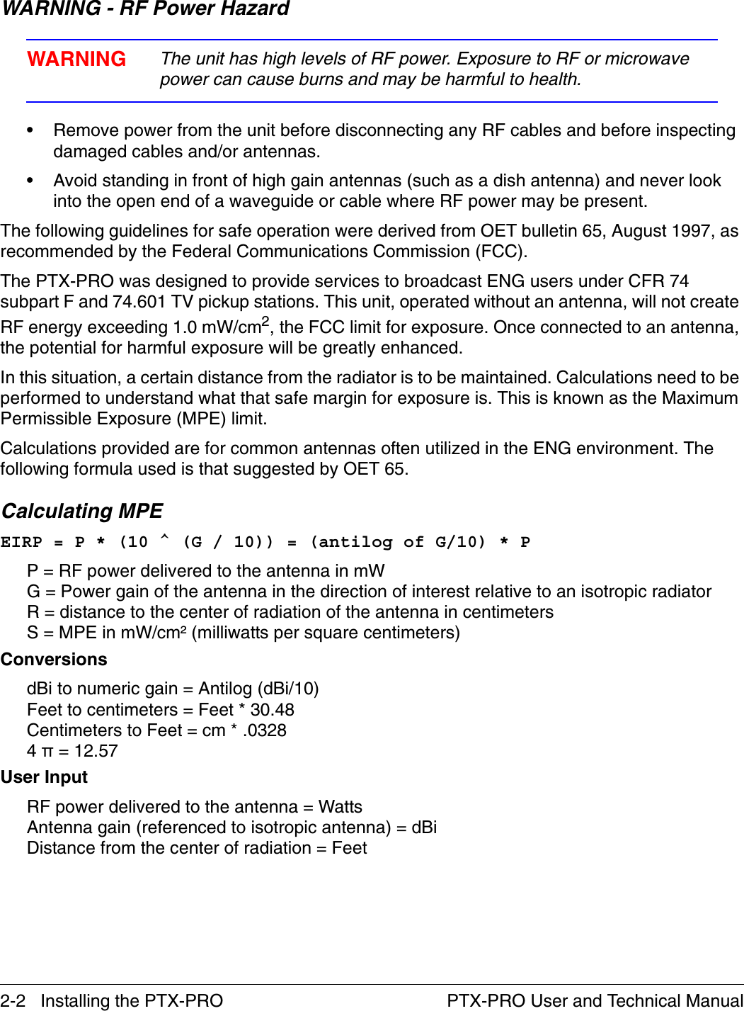
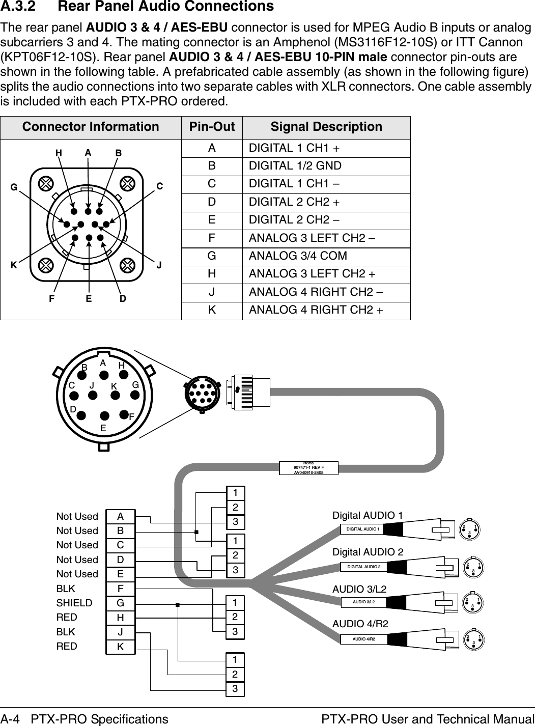
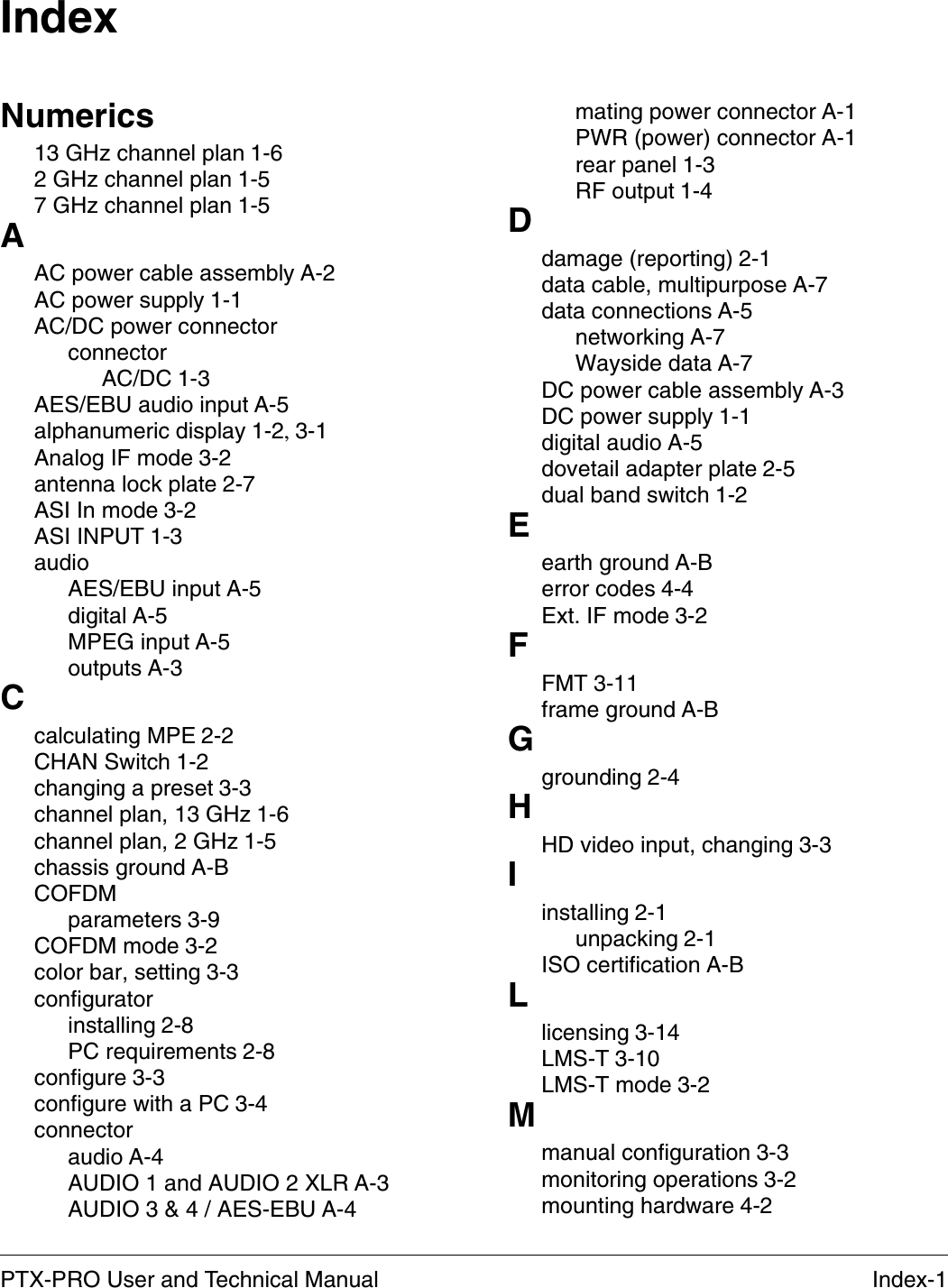
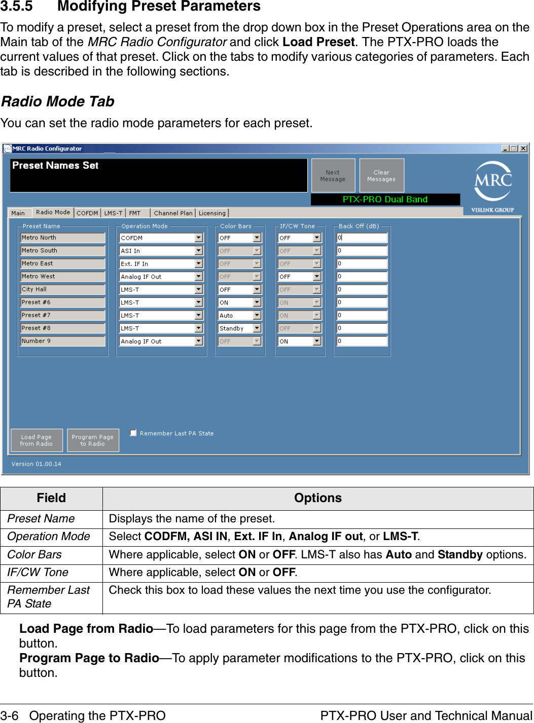
![Installing the PTX-PRO 2-3PTX-PRO User and Technical ManualCalculation steps:1. [P] RF power input. Watts to milliwatts = Watts * 10002. [G] Antenna gain dBi. Numeric gain = Antilog (dBi/10)3. [EIRP] Multiply P * G 4. [R] Centimeters to feet = Centimeters * .03285. Square R6. Multiply R² * 4π7. [S] Divide (R² * 4π) into EIRPS = Power Density in milliwatts per square centimeters. Note At frequencies above 1500 MHz, S must not be greater than 1.ReferenceFCC OET Bulletin 65, August 1997 - Evaluating Compliance with FCC Guidelines for Human Exposure to Radio Frequency Electromagnetic FieldsThe following graph and associated table show the permissible exposure distance for various antennas. Graphs and data will vary, based on the actual transmitter, output power, frequency, and antenna utilized. One plot provides the permissible output of the transmitter for digital modulation, and the other plot for analog modulation.This information is provided, in accordance with the requirements set forth by the FCC, as a guide for you assuming that users of this equipment are licensed and qualified to operate the equipment per the guidelines and recommendations contained within the product user guides and in accordance with any FCC rules that may apply.](https://usermanual.wiki/Microwave-Radio-Communications/PTX270AD/User-Guide-1517196-Page-13.png)
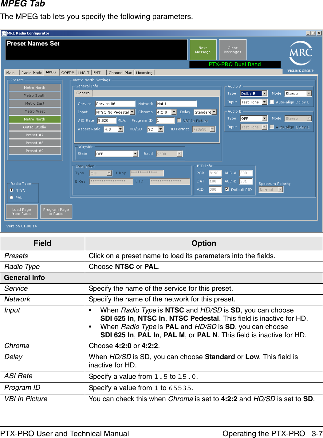
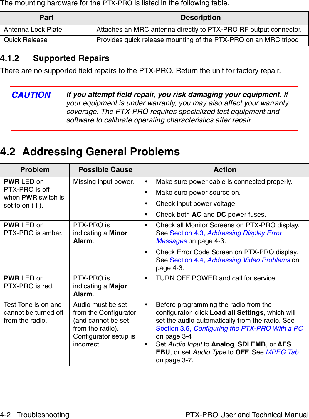
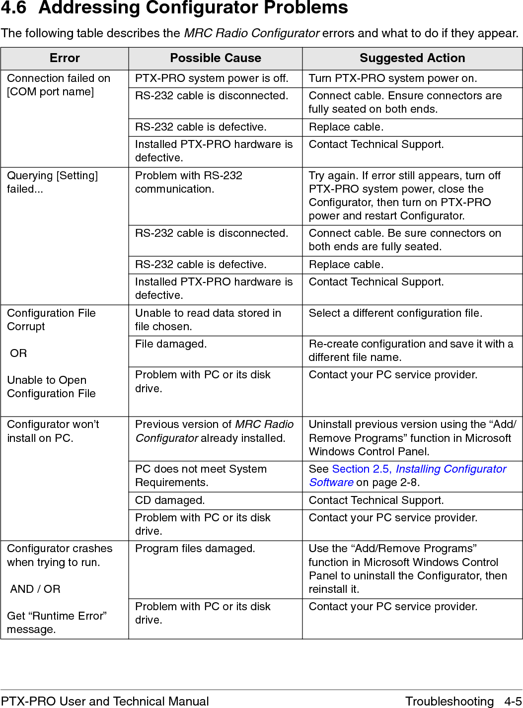
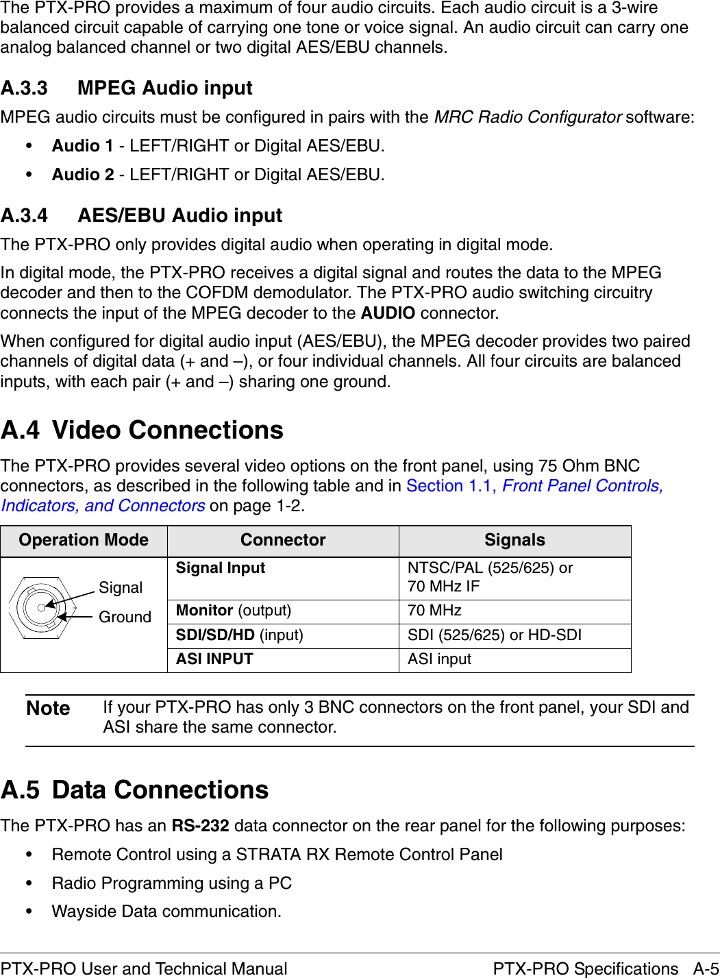
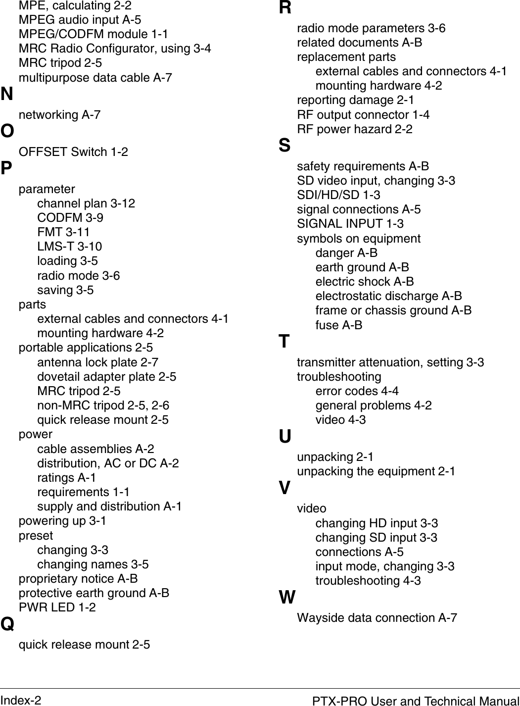
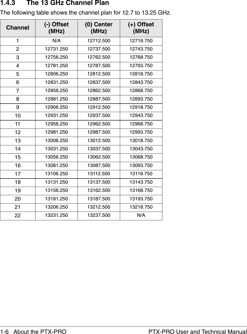
![Troubleshooting 4-5PTX-PRO User and Technical Manual4.6 Addressing Configurator ProblemsThe following table describes the MRC Radio Configurator errors and what to do if they appear. Error Possible Cause Suggested ActionConnection failed on [COM port name]PTX-PRO system power is off. Turn PTX-PRO system power on.RS-232 cable is disconnected. Connect cable. Ensure connectors are fully seated on both ends.RS-232 cable is defective. Replace cable.Installed PTX-PRO hardware is defective.Contact Technical Support.Querying [Setting] failed...Problem with RS-232 communication.Try again. If error still appears, turn off PTX-PRO system power, close the Configurator, then turn on PTX-PRO power and restart Configurator.RS-232 cable is disconnected. Connect cable. Be sure connectors on both ends are fully seated.RS-232 cable is defective. Replace cable.Installed PTX-PRO hardware is defective.Contact Technical Support.Configuration File Corrupt ORUnable to Open Configuration FileUnable to read data stored in file chosen.Select a different configuration file.File damaged. Re-create configuration and save it with a different file name.Problem with PC or its disk drive.Contact your PC service provider.Configurator won’t install on PC.Previous version of MRC Radio Configurator already installed.Uninstall previous version using the “Add/Remove Programs” function in Microsoft Windows Control Panel.PC does not meet System Requirements.See Section 2.5, Installing Configurator Software on page 2-8.CD damaged. Contact Technical Support.Problem with PC or its disk drive.Contact your PC service provider.Configurator crashes when trying to run. AND / ORGet “Runtime Error” message.Program files damaged. Use the “Add/Remove Programs” function in Microsoft Windows Control Panel to uninstall the Configurator, then reinstall it.Problem with PC or its disk drive.Contact your PC service provider.](https://usermanual.wiki/Microwave-Radio-Communications/PTX270AD/User-Guide-1517196-Page-37.png)