Microwave Radio Communications PTX270AD PTX-PRO Transmitter User Manual PTX PRO User and Tech
Microwave Radio Communications LLC PTX-PRO Transmitter PTX PRO User and Tech
Manual
User and Technical
PTX-PRO
Transmitter
Manual Part No. 400611-1 Rev. C July 2011
Copyright © 2011
Part number 400611-1
Printed in U.S.A.
Authorized EU representative: Vislink PLC
Quality Certification Vislink is certified to ISO 9001:2008.
The Vislink trademark and other trademarks are registered trademarks in the United States and/or other countries.
Microsoft®, Windows®, and Internet Explorer® are registered trademarks of Microsoft Corporation in the United States
and/or other countries.
Proprietary Material The information and design contained within this manual was originated by and is the property
of Vislink. Vislink reserves all patent proprietary design, manufacturing, reproduction use, and sales rights thereto, and
to any articles disclosed therein, except to the extent rights are expressly granted to others. The foregoing does not
apply to vendor proprietary parts. Vislink has made every effort to ensure the accuracy of the material contained in this
manual at the time of printing. As specifications, equipment, and this manual are subject to change without notice,
Vislink assumes no responsibility or liability whatsoever for any errors or inaccuracies that may appear in this manual
or for any decisions based on its use. This manual is supplied for information purposes only and should not be
construed as a commitment by Vislink. The information in this manual remains the property of Vislink and may not be
used, disclosed, or reproduced in any form whatsoever, without the prior written consent of Vislink. Vislink reserves the
right to make changes to equipment and specifications of the product described in this manual at any time without
notice and without obligation to notify any person of such changes.
General Safety Information The following safety requirements, as well as local site requirements and regulations,
must be observed by personnel operating and maintaining the equipment covered by this manual to ensure awareness
of potential hazards. This equipment has been tested and found to comply with the limits for a Class A digital device,
pursuant to Part 15 of the FCC Rules. These limits are designed to provide reasonable protection against harmful
interference when the equipment is operated in a commercial environment. This equipment generates, uses, and can
radiate radio frequency energy. If not installed and used in accordance with the instruction manual, it may cause
harmful interference to radio communications. Operation of this equipment in a residential area is likely to cause
harmful interference in which case the user will be required to correct the interference at his own expense.
About this Manual This manual is intended for use by qualified operators, installers, and service personnel. Users of
this manual should already be familiar with basic concepts of radio, video, and audio. For information about terms in
this manual, see Glossary of Terms and Abbreviations (Part No. 400576-1). Pay special attention to Notes, Cautions,
and Warnings.
Read Notes for important information to assist you in using and maintaining the equipment.
Follow CAUTIONS to prevent damage to the equipment.
Follow WARNINGS to prevent personal injury or death.
Symbols The following symbols may be on the equipment or in this manual:
WARNING: General Warning.
Risk of Danger.
Frame or Chassis Ground: Identifies the frame
or chassis terminal.
WARNING: Risk of Electric Shock. Earth Ground: Identifies the earth ground
terminal.
CAUTION: Electrostatic Discharge.
Possible Damage to Equipment. Fuse (either icon):
Identifies fuses or their location.
Protective Earth Ground: Identifies any
terminal intended for connection to an
external conductor for protection against elec-
tric shock in case of a fault, or the
terminal on a protective earth electrode.
Waste Electrical and Electronic Equipment
(WEEE): The product must not be disposed of
with other waste. You must dispose of the
waste equipment by handing it over to a desig-
nated collection point for recycling.
101 Billerica Avenue - Bldg. 6
North Billerica, MA 01862-1256 USA
TEL: 800.490.5700 or +1.978.671.5700

Contents-1PTX-PRO User and Technical Manual
Contents
1 About the PTX-PRO
1.1 Front Panel Controls, Indicators, and Connectors - - - - - - - - - - - - - - - - - - - 1-2
1.2 Rear Panel Connectors and Fuses - - - - - - - - - - - - - - - - - - - - - - - - - - - - - - 1-3
1.3 Related Documents- - - - - - - - - - - - - - - - - - - - - - - - - - - - - - - - - - - - - - - - - 1-4
1.4 Channel Plans (2, 7, and 13) - - - - - - - - - - - - - - - - - - - - - - - - - - - - - - - - - - 1-5
1.4.1 The 2 GHz Channel Plan - - - - - - - - - - - - - - - - - - - - - - - - - - - - - - - - - 1-5
1.4.2 The 7 GHz Channel Plan - - - - - - - - - - - - - - - - - - - - - - - - - - - - - - - - - 1-5
1.4.3 The 13 GHz Channel Plan - - - - - - - - - - - - - - - - - - - - - - - - - - - - - - - - 1-6
2 Installing the PTX-PRO
2.1 Unpacking the PTX-PRO - - - - - - - - - - - - - - - - - - - - - - - - - - - - - - - - - - - - - 2-1
2.2 Preparing to Install the PTX-PRO - - - - - - - - - - - - - - - - - - - - - - - - - - - - - - - 2-1
2.2.1 Operating in Safety - - - - - - - - - - - - - - - - - - - - - - - - - - - - - - - - - - - - - 2-1
2.2.2 Powering and Grounding the PTX-PRO- - - - - - - - - - - - - - - - - - - - - - - 2-4
2.3 Mounting on an MRC Tripod - - - - - - - - - - - - - - - - - - - - - - - - - - - - - - - - - - 2-5
2.4 Mounting on a Non-MRC Tripod - - - - - - - - - - - - - - - - - - - - - - - - - - - - - - - - 2-5
2.5 Installing Configurator Software - - - - - - - - - - - - - - - - - - - - - - - - - - - - - - - - 2-8
3 Operating the PTX-PRO
3.1 Powering Up- - - - - - - - - - - - - - - - - - - - - - - - - - - - - - - - - - - - - - - - - - - - - - 3-1
3.2 Using the Display Screen- - - - - - - - - - - - - - - - - - - - - - - - - - - - - - - - - - - - - 3-1
3.3 Monitoring PTX-PRO Operations - - - - - - - - - - - - - - - - - - - - - - - - - - - - - - - 3-2
3.4 Configuring the PTX-PRO Manually - - - - - - - - - - - - - - - - - - - - - - - - - - - - - 3-3
3.5 Configuring the PTX-PRO With a PC - - - - - - - - - - - - - - - - - - - - - - - - - - - - 3-4
3.5.1 Connecting the PTX-PRO to the MRC Radio Configurator - - - - - - - - - 3-4
3.5.2 Loading Parameters from the Radio or a File - - - - - - - - - - - - - - - - - - - 3-5
3.5.3 Saving Parameters to the Radio or a File- - - - - - - - - - - - - - - - - - - - - - 3-5
3.5.4 Changing the Name of a Preset - - - - - - - - - - - - - - - - - - - - - - - - - - - - 3-5
3.5.5 Modifying Preset Parameters - - - - - - - - - - - - - - - - - - - - - - - - - - - - - - 3-6
4 Troubleshooting
4.1 Getting Support for Your PTX-PRO - - - - - - - - - - - - - - - - - - - - - - - - - - - - - 4-1
4.1.1 Replacement Parts - - - - - - - - - - - - - - - - - - - - - - - - - - - - - - - - - - - - - 4-1
4.1.2 Supported Repairs - - - - - - - - - - - - - - - - - - - - - - - - - - - - - - - - - - - - - 4-2
4.2 Addressing General Problems - - - - - - - - - - - - - - - - - - - - - - - - - - - - - - - - - 4-2
4.3 Addressing Display Error Messages - - - - - - - - - - - - - - - - - - - - - - - - - - - - - 4-3
4.4 Addressing Video Problems - - - - - - - - - - - - - - - - - - - - - - - - - - - - - - - - - - - 4-3
4.5 Addressing Error Codes - - - - - - - - - - - - - - - - - - - - - - - - - - - - - - - - - - - - - 4-4
4.6 Addressing Configurator Problems - - - - - - - - - - - - - - - - - - - - - - - - - - - - - - 4-5

Contents-2 PTX-PRO User and Technical Manual
A PTX-PRO Specifications
A.1 PTX-PRO Physical Specifications - - - - - - - - - - - - - - - - - - - - - - - - - - - - - - A-1
A.2 Power Connections- - - - - - - - - - - - - - - - - - - - - - - - - - - - - - - - - - - - - - - - - A-1
A.2.1 Power Supply and Distribution - - - - - - - - - - - - - - - - - - - - - - - - - - - - - A-1
A.3 Audio Connections - - - - - - - - - - - - - - - - - - - - - - - - - - - - - - - - - - - - - - - - - A-3
A.3.1 Front Panel Audio Connections - - - - - - - - - - - - - - - - - - - - - - - - - - - - A-3
A.3.2 Rear Panel Audio Connections- - - - - - - - - - - - - - - - - - - - - - - - - - - - - A-4
A.3.3 MPEG Audio input - - - - - - - - - - - - - - - - - - - - - - - - - - - - - - - - - - - - - A-5
A.3.4 AES/EBU Audio input - - - - - - - - - - - - - - - - - - - - - - - - - - - - - - - - - - - A-5
A.4 Video Connections - - - - - - - - - - - - - - - - - - - - - - - - - - - - - - - - - - - - - - - - - A-5
A.5 Data Connections - - - - - - - - - - - - - - - - - - - - - - - - - - - - - - - - - - - - - - - - - - A-5
A.5.1 Wayside Data - - - - - - - - - - - - - - - - - - - - - - - - - - - - - - - - - - - - - - - - - A-7
A.5.2 Networking - - - - - - - - - - - - - - - - - - - - - - - - - - - - - - - - - - - - - - - - - - - A-7
Index
1
About the PTX-PRO 1-1PTX-PRO User and Technical Manual
About the PTX-PRO
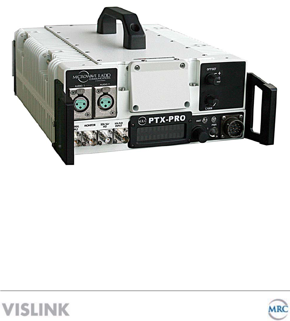
The PTX-PRO (see figure) is a versatile portable transmitter supporting many options and
configurations. The transmitter supports digital, or digital and analog modulation accepting a
wide range of inputs, such as composite video/audio, HD/SD SDI, ASI or external 70 MHz IF
signal. The PTX-PRO is available for single band operation at 2, 7, or 13 GHz, or for dual band
operation at 2 and 7 GHz.
The PTX-PRO provides for
video microwave
communications and is a highly
reliable, flexible, and compact
portable microwave transmitter
for either tripod or mobile
applications.
The PTX-PRO is ideal for
portable Electronic News
Gathering (ENG), Digital Video
Broadcasting (DVB), mobile
communications, wireless airborne networks, and Outside Broadcast (OB) systems.
The RF frequency synthesizer circuit included in the IF/RF module, in conjunction with the
command and control power supply module, creates RF video and audio signal channels in the
various standard FCC band plans. You can use standard U.S. FCC band plans or create
custom channel plans using the MRC Radio Configurator software on a PC.
The PTX-PRO includes MPEG/CODFM modules that can serve as a stand-alone digital video
and audio encoder. Additionally, both NTSC or PAL analog video are available.
The PTX-PRO is fully compatible with the MRC family of transmit antennas, including the
following:
• MRC MegaHorn Compact Horn antennas
• MRC 2, 3, and 4 ft. parabolic antennas
The PTX-PRO contains a universal AC/DC power supply and can operate on either external AC
or DC power sources. The PTX-PRO has the following power requirements, depending upon
the power option utilized.
Supply Voltage: +11.0—+36.0 Volts DC
90—264 VAC, 50/60 Hz
Power Consumption: 50 watts nominal
1-2 About the PTX-PRO PTX-PRO User and Technical Manual
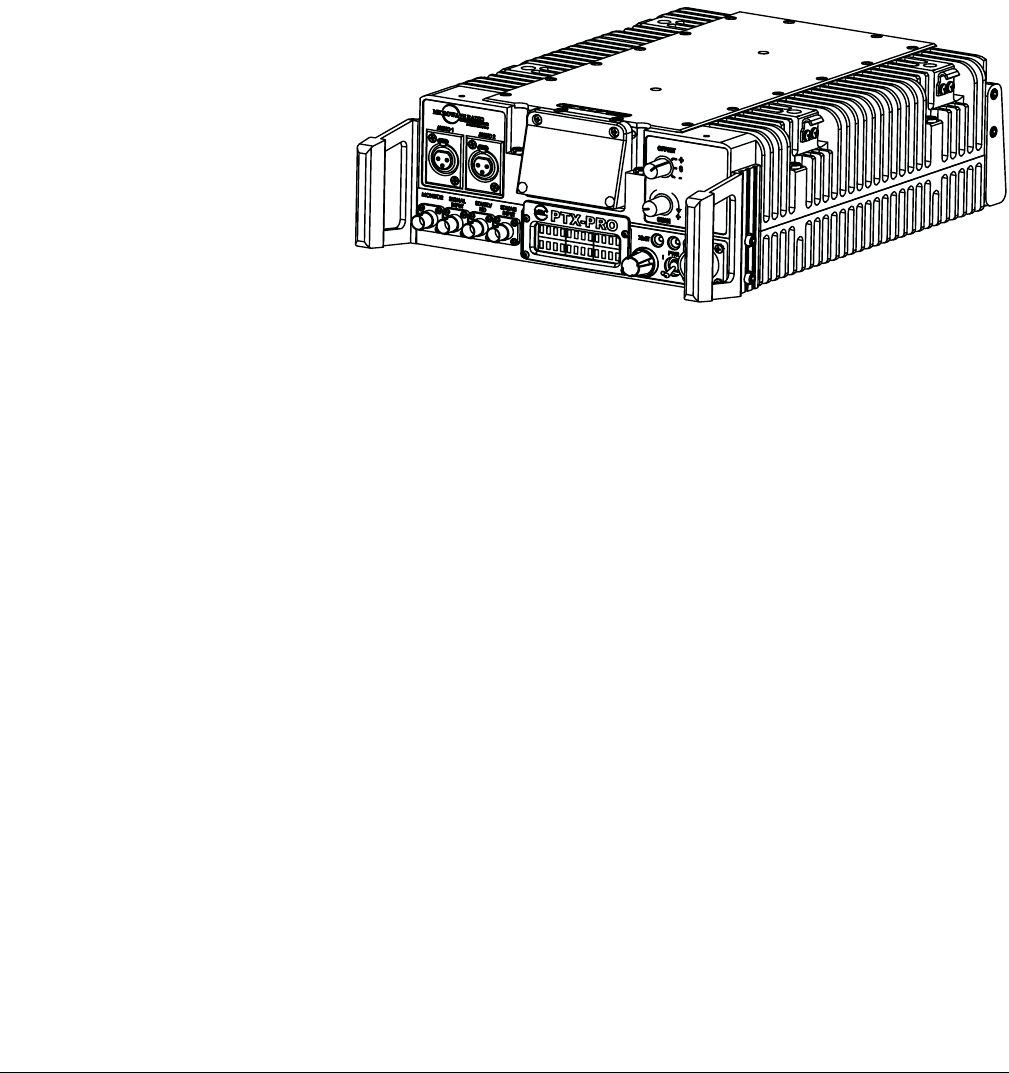
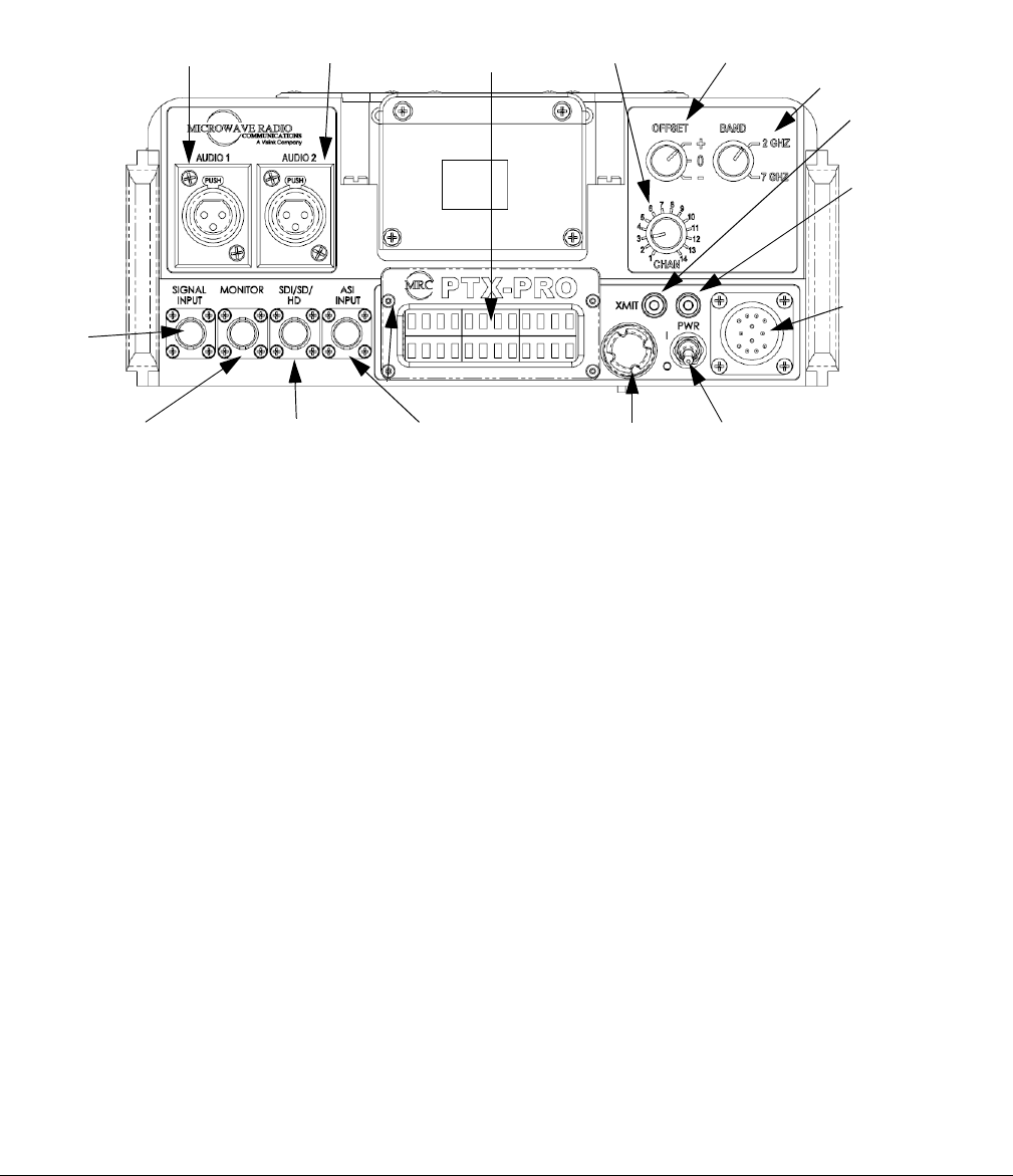
1.1 Front Panel Controls, Indicators, and Connectors
Each of these controls, indicators, and connectors are described in more detail in the following
paragraphs. Controls, indicators, and connectors contained on the PTX-PRO front panel are
shown in the following figure. A dual band switch is added to the indicated position if you order
the 2 and 7 GHz dual band option.
AUDIO 1 and AUDIO 2 XLR Connectors Provides balanced audio inputs for audio
subcarriers 1 and 2 or MPEG L1/R1.
Alphanumeric Screen Displays 2 lines of 12 alphanumeric characters in conjunction with the
control switch to monitor system status and to control system settings.
CHAN Switch Lets you choose the operating channel: 2 GHz (1—10), 7 GHz (1—14) and 13
GHz (1—22). The selected channel displays on the Main screen. See Section 1.4, Channel
Plans (2, 7, and 13) on page 1-5 for information about channel plans.
OFFSET Switch Lets you set the channel offset (+, 0, or –) channel offset. Note: For the 13
GHz plan, you cannot select offset – (minus) for Channel 1 and you cannot select offset + (plus)
for Channel 22.
Dual Band Switch On PRX-PRO dual band models only: lets you set the channel to 2 GHz or
7 GHz.
XMIT LED Displays Status as follows when the control switch is pushed:
Blue—Transmit mode.
None—Standby mode.
PWR LED Displays status as follows:
None—No power to the unit.
Green—Operational and no errors.
Amber—Abnormal condition that might impair performance.
Red—Failure or error that prevents normal operation.
AUDIO 2
Connector
AUDIO 1
Connector
CHAN
Switch
OFFSET
Switch
Alphanumeric
Display
MONITOR
Connector
SIGNAL
INPUT
Connecto
ASI INPUT
Connector
AC/DC
Power
Connector
PWR
Switch
PWR
LED
XMIT
LED
Control
Switch
SDI/SD/HD
Connector
Dual Band
Switch (dual
band models only)
About the PTX-PRO 1-3PTX-PRO User and Technical Manual
WARNING A Major Alarm (red PWR LED) may also indicate a potential safety
hazard.
Shut down the PTX-PRO transmitter and disconnect power.
AC/DC Power Connector Provides external AC or DC power sources.
PWR Switch Controls application of AC or DC power to the PTX-PRO.
Control Switch Turns clockwise to access status monitoring; see Section 3.3, Monitoring PTX-
PRO Operations on page 3-2. Turns counterclockwise to set device parameters; see
Section 3.4, Configuring the PTX-PRO Manually on page 3-3. Press the control switch to set a
parameter or lock a display (while it continues to update); press it again to unlock it.
ASI INPUT 75 Ohm BNC Female Connector Provides ASI inputs to the unit.
SDI/HD/SD 75 Ohm BNC Female Connector Provides the HD/SD/SDI data stream input to the
unit.
MONITOR 75 Ohm BNC Female Connector Provides 70 MHz output for external signal
monitoring.
SIGNAL INPUT 75 Ohm BNC Female Connector Provides the input connection for 70 MHz IF,
composite video (CV) (PAL or NTSC).
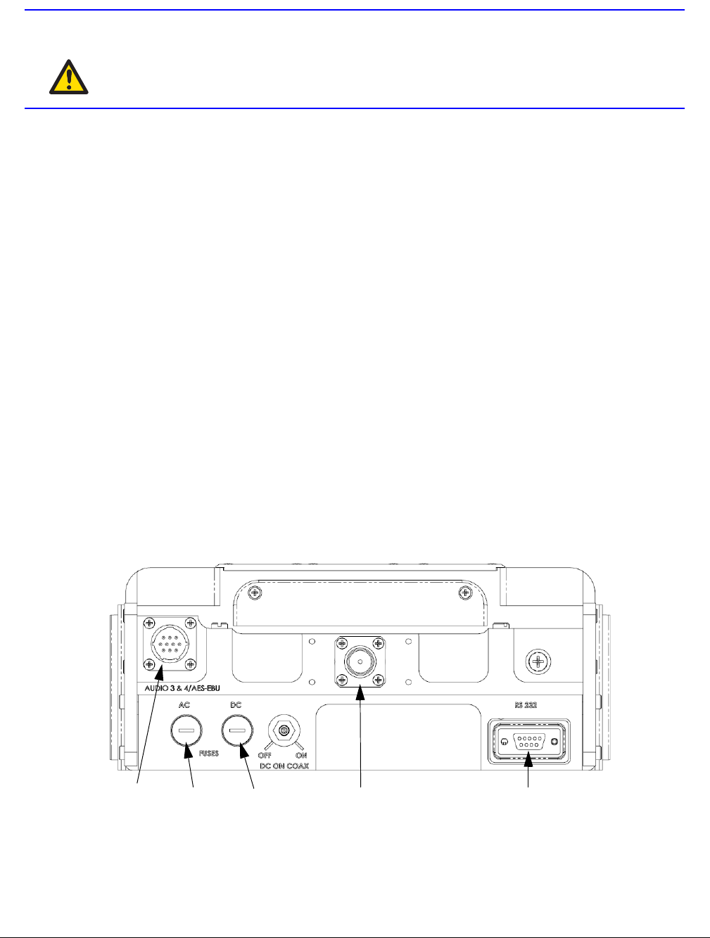
1.2 Rear Panel Connectors and Fuses
Controls, fuses, and connectors contained on the PTX-PRO rear panel are shown in the
following figure.
AUDIO 3 & 4,
L2/R2, or
AES-EBU
Connector
AC Fuse DC Fuse RF Output
Connector
RS 232
Connector
1-4 About the PTX-PRO PTX-PRO User and Technical Manual
AUDIO 3 & 4, L2/R2, or AES-EBU 10-Pin Female Connector Receives balanced audio inputs
for audio subcarriers 3 and 4 or MPEG L2/R2.
RF Output Type “N” 50 Ohm Female Connector Provides the RF output to the transmitting
antenna. The universal type “N” connector lets you use PTX-PRO for emergency restoration of
a Studio-Transmitter Link (STL) or Inter-City Relay (ICR) link.
AC Fuse Provides AC input power protection for units used with AC power sources.
DC Fuse Provides DC input power protection for units used with DC power sources.
CAUTION Avoid possible equipment damage. If you are using a DC power source
for your PTX-PRO, do not exceed 36 volts DC input power.
RS-232 DB-9 Connector Provides a connection to a Windows-based PC when using the
Configurator software or connection for Wayside data.
1.3 Related Documents
• Glossary of Terms and Abbreviations (Part No. 400576-1)
• Channels and Frequencies Technical Information (Part No. 400580-1)
• Link Quality Technical Information (Part No. 400585-1)
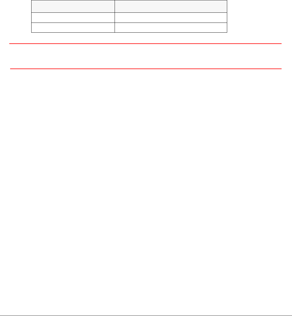
Operating Voltage Fuse Rating
90 to 264 VAC, 50/60 Hz 2.0A, 250V AGC, Slow Blow
+11.0 to +36.0 VDC 15.0A, 250V, Slow Blow
About the PTX-PRO 1-5PTX-PRO User and Technical Manual
1.4 Channel Plans (2, 7, and 13)
1.4.1 The 2 GHz Channel Plan
The following table shows the 2 GHz BAS channel plan.
1.4.2 The 7 GHz Channel Plan
The following table shows the channel plan for 6.4 to 7.2 GHz.
BAS
Channel
(-) Offset
(MHz)
(0) Offset
(MHz)
(+) Offset
(MHz)
1 2028.500 2031.500 2034.500
2 2040.500 2043.500 2046.500
3 2052.500 2055.500 2058.500
4 2064.500 2067.500 2070.500
5 2076.500 2079.500 2082.500
6 2088.500 2091.500 2094.500
7 2100.500 2103.500 2106.500
8 2454.250 2458.500 2462.750
9 2471.000 2475.250 2479.500
10 2487.500 2491.750 2496.000
Channel (-) Offset
(MHz)
(0) Center
(MHz)
(+) Offset
(MHz)
1 6881.250 6887.500 6893.750
2 6906.250 6912.500 6918.750
3 6931.250 6937.500 6943.750
4 6956.250 6962.500 6968.750
5 6981.250 6987.500 6993.750
6 7006.250 7012.500 7018.750
7 7031.250 7037.500 7043.750
8 7056.250 7062.500 7068.750
9 7081.250 7087.500 7093.750
10 7106.750 7112.500 7118.750
11 6431.250 6437.500 6443.750
12 6456.250 6462.500 6468.750
13 6481.250 6487.500 6493.750
14 6506.250 6512.500 6518.750

1-6 About the PTX-PRO PTX-PRO User and Technical Manual
1.4.3 The 13 GHz Channel Plan
The following table shows the channel plan for 12.7 to 13.25 GHz.
Channel (-) Offset
(MHz)
(0) Center
(MHz)
(+) Offset
(MHz)
1N/A 12712.500 12718.750
212731.250 12737.500 12743.750
312756.250 12762.500 12768.750
412781.250 12787.500 12793.750
512806.250 12812.500 12818.750
612831.250 12837.500 12843.750
712856.250 12862.500 12868.750
812881.250 12887.500 12893.750
912906.250 12912.500 12918.750
10 12931.250 12937.500 12943.750
11 12956.250 12962.500 12968.750
12 12981.250 12987.500 12993.750
13 13006.250 13012.500 13018.750
14 13031.250 13037.500 13043.750
15 13056.250 13062.500 13068.750
16 13081.250 13087.500 13093.750
17 13106.250 13112.500 13118.750
18 13131.250 13137.500 13143.750
19 13156.250 13162.500 13168.750
20 13181.250 13187.500 13193.750
21 13206.250 13212.500 13218.750
22 13231.250 13237.500 N/A

2
Installing the PTX-PRO 2-1PTX-PRO User and Technical Manual
Installing the PTX-PRO
This chapter describes how to install Transmitter (PTX-PRO).
CAUTION If you modify the product without authorization from Vislink, you will void
the warranty.
2.1 Unpacking the PTX-PRO
Carefully unpack your new equipment to avoid damage.
• Locate all parts and accessories and verify that they are listed on the packing list.
Note DO NOT discard the container or packing material until you have inspected the
equipment and are sure there is no shipping damage. The container and
packing must be available in case you need to file a damage claim with the
shipping carrier.
• Inspect the equipment for damage and that it is clean and dry.
• Inspect the cables, connectors, switches, and displays to ensure that they are not
broken, damaged, or loose.
If you discover damage after unpacking the system, report the damage as follows:
• Immediately file a claim with the shipping carrier.
• Forward a copy of the damage report to Vislink Customer Service.
• Contact Vislink Customer Service to determine the disposition of the equipment. See
Section 4.1, Getting Support for Your PTX-PRO on page 4-1.
2.2 Preparing to Install the PTX-PRO
The following sections describe the things you should consider before installing the DXL8000.
2.2.1 Operating in Safety
CAUTION Ensure that the power being supplied matches the power required by
the equipment. You can find power ratings for equipment on a rating
plate, usually on the rear panel. Ensure that the electrical supply is
protected by over-current protection devices as required by the
applicable electrical codes. If necessary, consult a licensed electrician.

2-2 Installing the PTX-PRO PTX-PRO User and Technical Manual
WARNING - RF Power Hazard
WARNING The unit has high levels of RF power. Exposure to RF or microwave
power can cause burns and may be harmful to health.
• Remove power from the unit before disconnecting any RF cables and before inspecting
damaged cables and/or antennas.
• Avoid standing in front of high gain antennas (such as a dish antenna) and never look
into the open end of a waveguide or cable where RF power may be present.
The following guidelines for safe operation were derived from OET bulletin 65, August 1997, as
recommended by the Federal Communications Commission (FCC).
The PTX-PRO was designed to provide services to broadcast ENG users under CFR 74
subpart F and 74.601 TV pickup stations. This unit, operated without an antenna, will not create
RF energy exceeding 1.0 mW/cm2, the FCC limit for exposure. Once connected to an antenna,
the potential for harmful exposure will be greatly enhanced.
In this situation, a certain distance from the radiator is to be maintained. Calculations need to be
performed to understand what that safe margin for exposure is. This is known as the Maximum
Permissible Exposure (MPE) limit.
Calculations provided are for common antennas often utilized in the ENG environment. The
following formula used is that suggested by OET 65.
Calculating MPE
EIRP = P * (10 ^ (G / 10)) = (antilog of G/10) * P
P = RF power delivered to the antenna in mW
G = Power gain of the antenna in the direction of interest relative to an isotropic radiator
R = distance to the center of radiation of the antenna in centimeters
S = MPE in mW/cm² (milliwatts per square centimeters)
Conversions
dBi to numeric gain = Antilog (dBi/10)
Feet to centimeters = Feet * 30.48
Centimeters to Feet = cm * .0328
4 π = 12.57
User Input
RF power delivered to the antenna = Watts
Antenna gain (referenced to isotropic antenna) = dBi
Distance from the center of radiation = Feet

Installing the PTX-PRO 2-3PTX-PRO User and Technical Manual
Calculation steps:
1. [P] RF power input. Watts to milliwatts = Watts * 1000
2. [G] Antenna gain dBi. Numeric gain = Antilog (dBi/10)
3. [EIRP] Multiply P * G
4. [R] Centimeters to feet = Centimeters * .0328
5. Square R
6. Multiply R² * 4π
7. [S] Divide (R² * 4π) into EIRP
S = Power Density in milliwatts per square centimeters.
Note At frequencies above 1500 MHz, S must not be greater than 1.
Reference
FCC OET Bulletin 65, August 1997 - Evaluating Compliance with FCC Guidelines for
Human Exposure to Radio Frequency Electromagnetic Fields
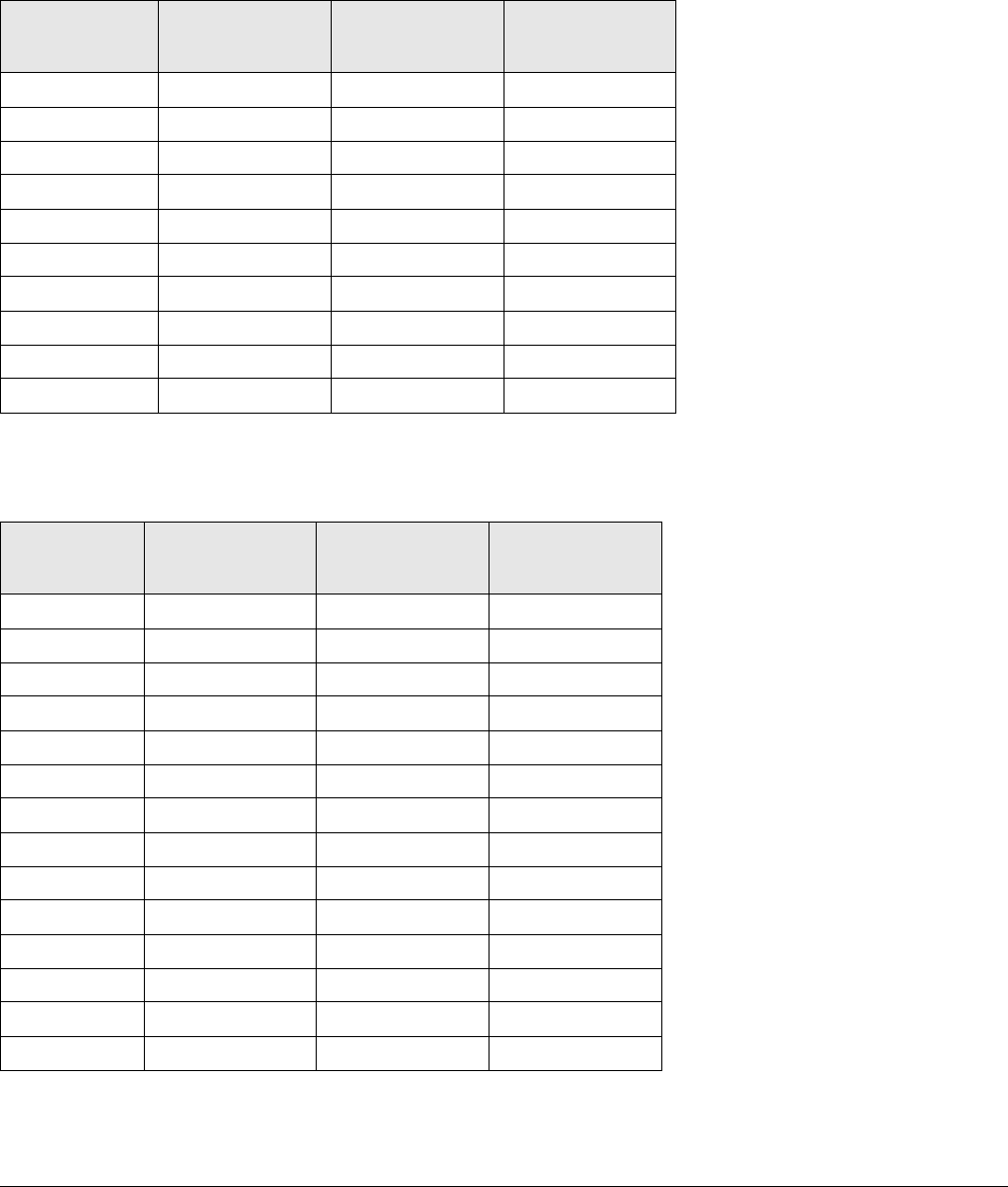
The following graph and associated table show the permissible exposure distance for various
antennas. Graphs and data will vary, based on the actual transmitter, output power, frequency,
and antenna utilized. One plot provides the permissible output of the transmitter for digital
modulation, and the other plot for analog modulation.
This information is provided, in accordance with the requirements set forth by the FCC, as a
guide for you assuming that users of this equipment are licensed and qualified to operate the
equipment per the guidelines and recommendations contained within the product user guides
and in accordance with any FCC rules that may apply.
2-4 Installing the PTX-PRO PTX-PRO User and Technical Manual
2.2.2 Powering and Grounding the PTX-PRO
For safe operation, all equipment must be properly grounded.
• Connect the unit to a common (vehicle or aircraft) ground.
• Make the ground wire as short and straight as possible.
CAUTION Be sure the equipment grounding follows applicable electrical codes.
Never modify a grounded power plug to connect to an ungrounded
receptacle.
Ensure that the power being supplied matches the power required by
the equipment. You can find power ratings for equipment on a rating
plate, usually on the rear panel. Ensure that the electrical supply is
protected by over-current protection devices as required by the
applicable electrical codes. If necessary, consult a licensed electrician.
Antenna
Gain (dBi)
Minimum Safe
Distance from
Antenna (cm)
Minimum Safe
Distance from
Antenna (inch)
020 7.9
532 12.6
16 113 44.5
20 178 70.1
35 1001 394.1
Installing the PTX-PRO 2-5PTX-PRO User and Technical Manual
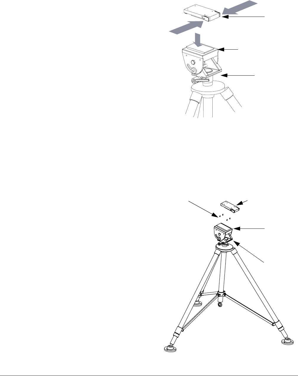
2.3 Mounting on an MRC Tripod
For portable applications, the PTX-PRO is moved
from place to place. The power, antenna, and audio/
video connections are set up and removed each
time.
You can attach the PTX-PRO to a Quick Release
Mount for easy mounting on an MRC tripod (see
figure). The Quick Release Mount is attached to the
bottom of the PTX-PRO using four 1/2-inch long, #6-
32, flat head screws.
You can keep the Quick Release Mount attached to
the PTX-PRO. The Quick Release Mount and PTX-
PRO are then attached to the Dovetail Adapter Plate
machined into the MRC tripod mount.
The versatility of the Quick Release Mount and a
mating Dovetail Adapter Plate let you attach the Dovetail Adapter Plate to the bottom of the
PTX-PRO and the Quick Release Mount to a non-MRC tripod, or vice versa.
2.4 Mounting on a Non-MRC Tripod
Option 1
To mount a PTX-PRO on a non-MRC tripod, attach
the Quick Release Mount to the bottom of the
PTX-PRO using four 1/2-inch long, #6-32, flat
head screws.
The Dovetail Adapter Plate is then attached to the
non-MRC tripod and the Quick Release Mount and
PTX-PRO assembly is attached to the Dovetail
Adapter Plate on the tripod mount.
Quick
Release
Mount
Dovetail Adapter
Plate (Machined)
MRC Tripod
Mount
Quick Release
Mount (Attached to
PTX-PRO)
Flat Head Screws
(4 Each)
Dovetail
Adapter
Plate
Tripod
Mount
2-6 Installing the PTX-PRO PTX-PRO User and Technical Manual
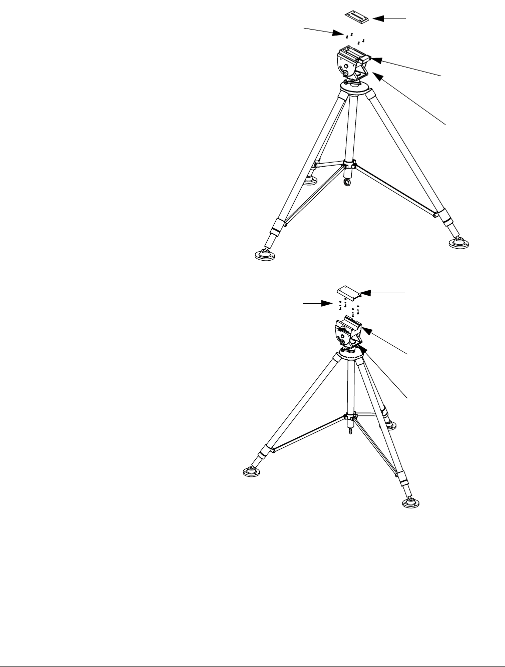
Option 2
To mount a PTX-PRO on a non-MRC tripod,
another option is to attach the Dovetail
Adapter Plate to the bottom of the PTX-PRO
using four 1/2-inch long, #6-32, flat head
screws.
The Quick Release Mount is then attached to
the non-MRC tripod and the Dovetail Adapter
Plate and PTX-PRO assembly is attached to
the Quick Release Mount on the tripod
mount.
Option 3
A third option is available to mount a
PTX-PRO to a non-MRC tripod that
contains a QuickSet tripod mount. This
option requires the use of a QuickSet
Quick Change Adapter.
The Quick Change Adapter is attached
to the bottom of the PTX-PRO using
four 1/2-inch long, #6-32, pan head
screws, lock washers, and flat washers.
The Quick Change Adapter and PTX-
PRO assembly is then attached to the
QuickSet tripod mount and is secured
with the tripod mount locking clamp.
Flat Head
Screws
(4 Each)
Quick
Release
Mount
Dovetail Adapter
Plate (Attached to
PTX-PRO)
Tripod
Mount
Pan Head Screws,
Lock Washers
and Flat Washers
(4 Each)
Tripod Mount
Locking Clamp
QuickSet Quick
Change Adapter
(Attached to
PTX-PRO)
QuickSet
Tripod
Mount
Installing the PTX-PRO 2-7PTX-PRO User and Technical Manual
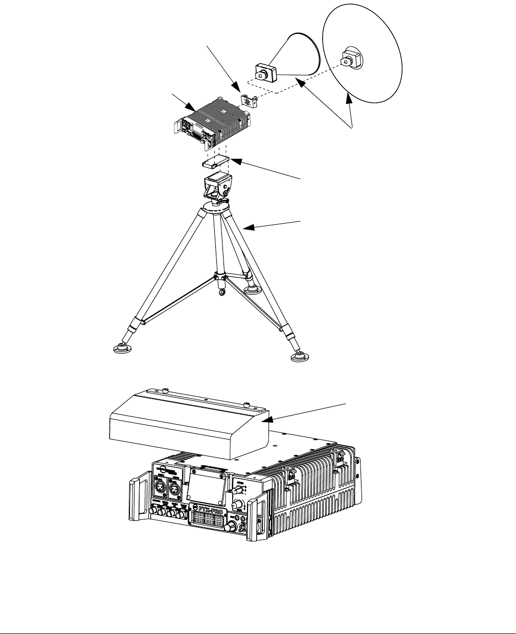
Final Mounting
When you mount the PTX-PRO on the tripod, the antenna typically is attached to the Antenna
Lock Plate mounted on the PTX-PRO as shown in the following figure.
An optional Rain Shield is also available for portable applications in inclement weather.
Antenna
(2 options shown)
Antenna
Lock Plate
PTX-PRO
Receiver
Quick Release
Mount
Tripod
Optional
Rain
Shield

2-8 Installing the PTX-PRO PTX-PRO User and Technical Manual
2.5 Installing Configurator Software
You can configure the PTX-PRO with a PC by installing the MRC Radio Configurator. Your PC
must meet the following minimum requirements.
•400 MHz
•96 RAM
• 800x600 Screen resolution
• Microsoft Windows XP Operating System with SP2
• 500 MB of free hard disk space
• CD-ROM drive
• Internet Explorer 4.01 SP1 or later
• One RS-232 I/O port configured as COM 1 thru COM 9.
To install the Configurator, insert the product CD and follow the instructions on the
Setup Wizard. Upon successful installation, the MRC Radio Configurator icon
displays on your desktop.
Note If you already have a version of the MRC Radio Configurator installed, you
must uninstall it using the Add/Remove Programs feature in the Microsoft
Windows Control Panel before attempting to install a new version.

3
Operating the PTX-PRO 3-1PTX-PRO User and Technical Manual
Operating the PTX-PRO
This chapter describes how to use the PTX-PRO Transmitter (PTX-PRO).
3.1 Powering Up
Before powering up the PTX-PRO, make sure to connect the cables to the correct connectors
and fully mate and lock the connections.
CAUTION Make sure the power supplied matches the power required by the unit.
When you set the PWR switch to I (on), the following sequence occurs:
1. The PWR LED above the PWR switch illuminates and changes colors from red, to green,
to amber, and finally to green and should remain green.
2. The alphanumeric display lights up and displays a self-test screen, then the version of
the firmware, and finally the default screen. The PTX-PRO uses the last settings in use
when power was turned off.
Test the performance of your PTX-PRO by setting up a link and transmitting and receiving video
and audio. If the PTX-PRO does not power up normally, see Chapter 4, Troubleshooting.
3.2 Using the Display Screen
The screen on the PTX-PRO transmitter displays the values of the selected preset and the
output power. For example:
Preset #1
0.00W C 1
The Control switch lets you monitor status and set functions, displayed on the PTX-PRO
screen. The Control Switch cycles through information when you turn it clockwise (for
Monitoring information; see Section 3.3) or counterclockwise (for Setting parameters; see
Section 3.4).
If you do not turn or press the control switch within 7 seconds, the screen reverts to the default
display. You can lock the display by pressing the Control switch; the display continues to update
the information. To unlock the display, press the Control switch again; the default screen
displays.
Use the CHAN and OFFSET Switches to select which channel to use. Verify the channel by
turning the Control switch clockwise to view the Channel Monitor screen, as shown in the
following example:
12712.500MHz
0.00W C 1

3-2 Operating the PTX-PRO PTX-PRO User and Technical Manual
3.3 Monitoring PTX-PRO Operations
Review Monitor screens by turning the Control switch clockwise. The sequence of screens
depends on the mode.
• Analog IF mode routes a 70 MHz IF signal through the transmitter to the Signal input
connector.
• ASI In mode supplies an ASI stream to the RF output monitor connectors.
• COFDM mode supplies a 70 MHz CODFM IF to the RF output and monitor connectors.
• Ext. IF mode supplies a 70 MHz IF input signal to the Signal Input connector of the
transmitter.
• LMS-T mode uses a single carrier modulator and supplies a configurable LMV-S signal
to the RF output and monitor connectors.
The following table shows the Monitor screen sequences of each mode.
Monitor Menu Sequence (Clockwise)
Analog IF ASI In CODFM Mode EXT IF Mode LMS-T Mode
12712.500MHz
0.00W C 1
12712.500MHz
0.00W C 1
12712.500MHz
0.00W C 1
12712.500MHz
0.00W C 1
12712.500MHz
0.00W C 1
TX Attn
0.0db
TX Attn
0.0db
TX Attn
0.0db
TX Attn
0.0db
TX Attn
0.0db
Band
13 GHz
Band
13 GHz
Band
13 GHz
Band
13 GHz
Band
13 GHz
Mode
Analog - IF
Mode
ASI/SDI In
Mode
COFDM
Mode
EXT IF Input
Mode
LMS-T
Audio #1 ON
Pre 4.83MHz
QPSK 8MHz
ASI 18.096Mb
FE1/2 GI1/32
64QAM 8MHz
ASI 18.096Mb
FE1/2 GI1/32
No Errors QPSK 10MHz
ASI 18.096Mb
FE1/2 GI1/32
Audio #2 ON
Pre 5.20MHz
IF CW OFF NTSC NoPdstl
Vid In 4:2:0
NTSC NoPdstl
Vid In 4:2:0
Audio #3 ON
Pre 5.80MHz
No Errors Video Delay
Normal
Video Delay
Normal
Audio #4 ON
Pre 6.20MHz
MPEG AudioA
AESEBU Streo
MPEG AudioA
AESEBU Streo
VID Dev 4MHz
PAL/No Video
MPEG AudioB
AESEBU Streo
MPEG AudioB
AESEBU Streo
IF CW OFF No Errors No Errors
No Errors

Operating the PTX-PRO 3-3PTX-PRO User and Technical Manual
3.4 Configuring the PTX-PRO Manually
This section describes how to configure your PTX-PRO with different settings using the front
panel switches. You can set presets, video input mode, color bar, and RF attenuation levels,
and set the channel and offset with associated switches.
To configure your PTX-PRO with a PC, see Section 3.5, Configuring the PTX-PRO With a PC
on page 3-4. The following table shows the sequence of screens displayed.
Setting Parameters Sequence
(Counterclockwise)
Function Display Example Setting Procedure
Change Preset Chng Preset
Preset #1
1. Press the Control switch; the preset line flashes.
2. Turn the Control switch to display the desired preset.
3. Press the Control switch to set the desired preset.
Change video
input mode
Chng VI Mode
SD
1. Press the Control Switch; the value flashes.
2. Turn the Control Switch to select SD or HD.
3. Press the Control switch to set the desired mode.
Change SD
video input
- OR -
Chng SD VI
NTSC
1. Press the Control Switch; the value flashes.
2. Turn the Control Switch to select NTSC, or NTSC
NoPdstl, or 525 Line SDI.
3. Press the Control switch to set the desired SD video
input.
Change HD
video input
Chng HD VI
720p60
1. Press the Control Switch; the value flashes.
2. Turn the Control Switch to select 720p50, 720p59,
720p60, or 1080i25, 1080i29,or 1080i30.
3. Press the Control switch to set the desired HD video
input.
Set Color Bar Chng CLR Bar
ON
1. Press the Control Switch; the value flashes.
2. Turn the Control Switch to select ON, or OFF, Auto Gen,
or Auto Standby.
3. Press the Control switch to set the desired option.
Set Transmitter
Attenuation
Set TX Attn
Attn: 0db
1. Press the Control Switch; the value flashes.
2. Turn the Control Switch to select 0 to –31 dB.
3. Press the Control switch to set the desired decibel value.
3-4 Operating the PTX-PRO PTX-PRO User and Technical Manual
3.5 Configuring the PTX-PRO With a PC
When you connect your PTX-PRO to a PC, you can create channel plans, and up-to-9 custom
presets. If you need more than 9 presets, create as many preset configurations as you want and
save them to a file, then load the configuration file when you need the saved presets.
CAUTION Do not make configuration changes to your PTX-PRO while it is
connected to a radio system that is actively transmitting because it will
interrupt broadcast operations. Do not place the PTX-PRO in transmit
mode when using the MRC Radio Configurator. Also, the PTX-PRO
must be powered up before you run the MRC Radio Configurator.
For information about installing the MRC Radio Configurator, see Section 2.5, Installing
Configurator Software on page 2-8.
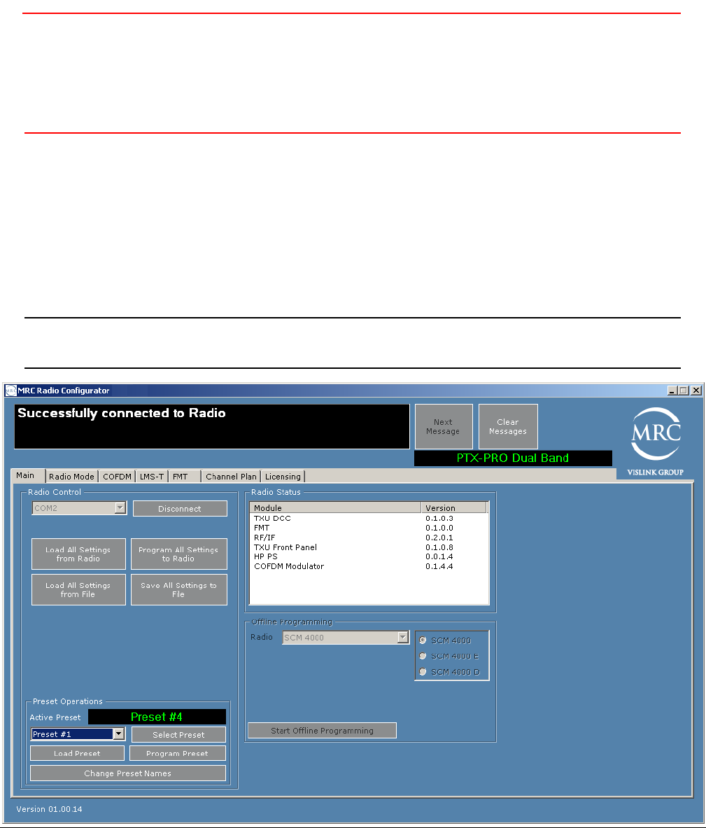
3.5.1 Connecting the PTX-PRO to the MRC Radio Configurator
On the Main tab of the MRC Radio Configurator, choose the COM port to which the PTX-PRO
is connected, and click Connect. The following figure shows that the MRC Radio Configurator
has connected to the PTX-PRO.
Tip Before you program the PTX-PRO with the MRC Radio Configurator, click
Load All Settings to populate the parameters as a template.
Operating the PTX-PRO 3-5PTX-PRO User and Technical Manual
The MRC Radio Configurator automatically detects your PTX-PRO, your hardware
configuration, and the licensed options contained in your PTX-PRO and loads a number of tabs
where you can set parameters for your PTX-PRO. Licensed options that are not contained in
your radio are not displayed in the MRC Radio Configurator tabs. For example, if you do not
have the LMS-T licensed option in your radio, the LMS-T tab does not appear or is inactive.
3.5.2 Loading Parameters from the Radio or a File
You can load parameters from the radio or a file before you modify it to suit your needs.
• To load parameter settings that are stored in the PTX-PRO into the MRC Radio
Configurator, click the Load All Settings from Radio box.
• To load parameter settings from a previously saved file, click the Load All Settings from
File box.
3.5.3 Saving Parameters to the Radio or a File
You can save the parameter settings to the radio or a file, as follows.
• To save parameter settings from the MRC Radio Configurator to the PTX-PRO, click the
Save All Settings to Radio box.
• To save parameter settings to a file, click the Save All Settings from File box.
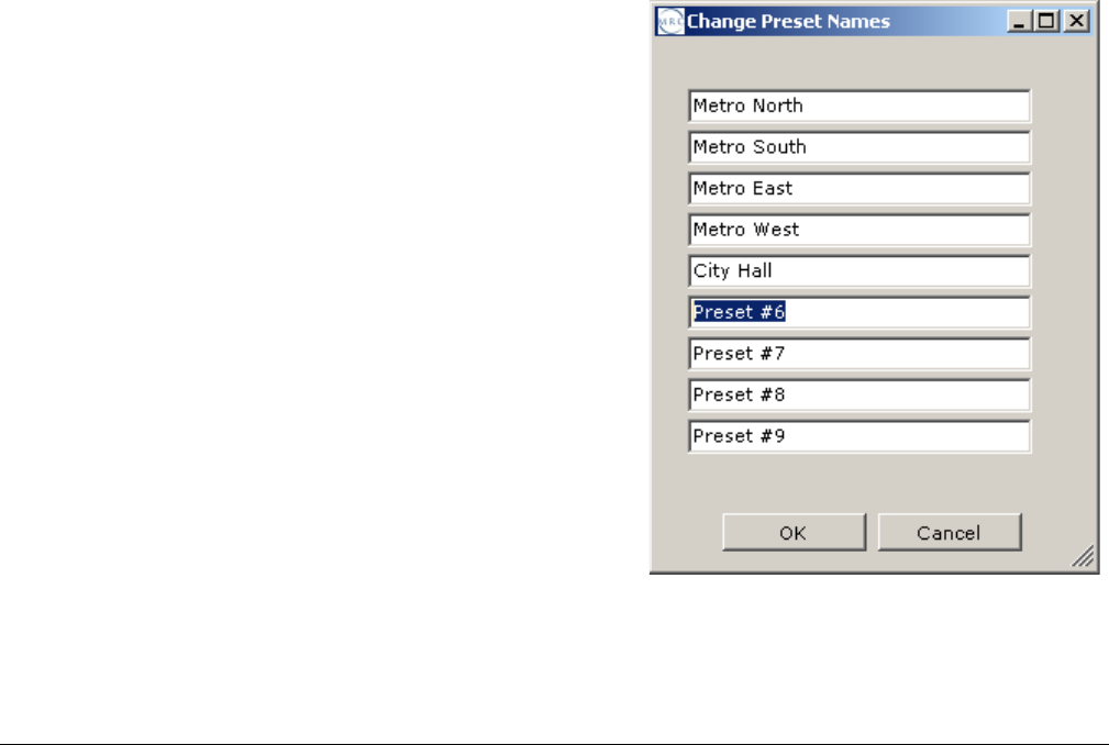
3.5.4 Changing the Name of a Preset
On the Main tab, choose Change Preset Names in
the Preset Operations section. The Change Preset
Names dialog box appears. The example figure
shows the dialog box with most of the 9 presets
renamed to indicate remote locations.
Click OK to set the preset names. The new names will
display on the PTX-PRO status screen and the MRC
Radio Configurator screens.
3-6 Operating the PTX-PRO PTX-PRO User and Technical Manual
3.5.5 Modifying Preset Parameters
To modify a preset, select a preset from the drop down box in the Preset Operations area on the
Main tab of the MRC Radio Configurator and click Load Preset. The PTX-PRO loads the
current values of that preset. Click on the tabs to modify various categories of parameters. Each
tab is described in the following sections.
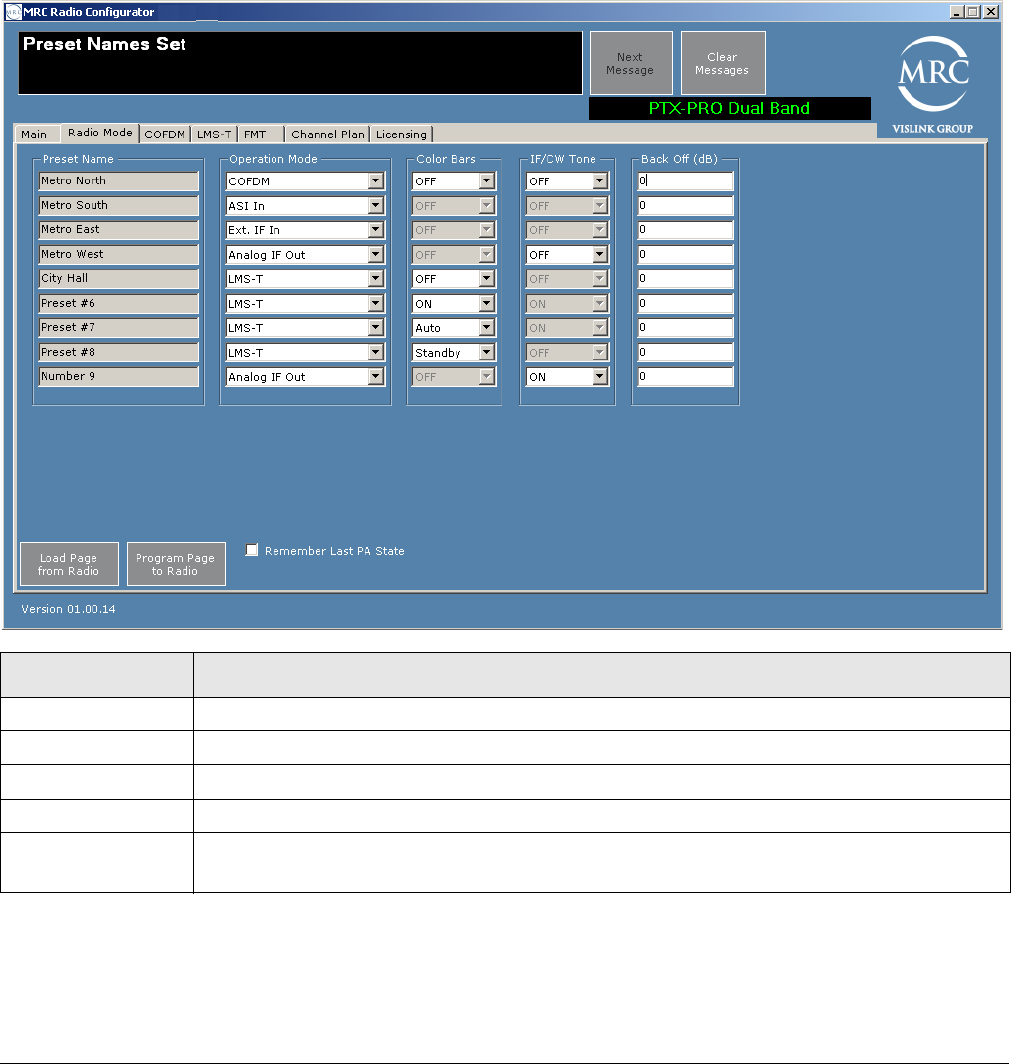
Radio Mode Tab
You can set the radio mode parameters for each preset.
Load Page from Radio—To load parameters for this page from the PTX-PRO, click on this
button.
Program Page to Radio—To apply parameter modifications to the PTX-PRO, click on this
button.
Field Options
Preset Name Displays the name of the preset.
Operation Mode Select CODFM, ASI IN, Ext. IF In, Analog IF out, or LMS-T.
Color Bars Where applicable, select ON or OFF. LMS-T also has Auto and Standby options.
IF/CW Tone Where applicable, select ON or OFF.
Remember Last
PA State
Check this box to load these values the next time you use the configurator.
Operating the PTX-PRO 3-7PTX-PRO User and Technical Manual
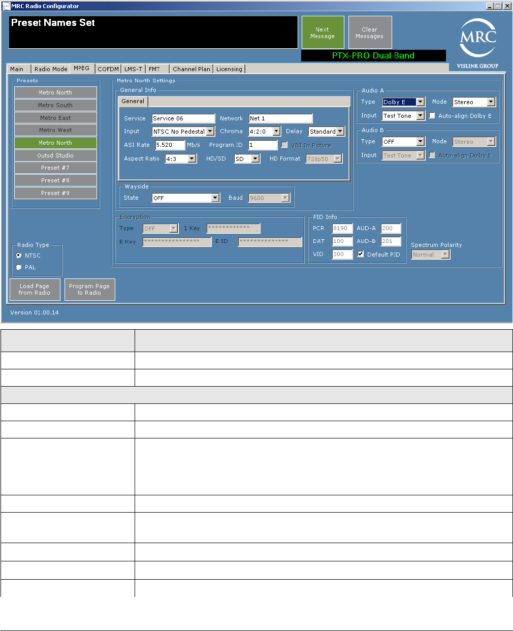
MPEG Tab
The MPEG tab lets you specify the following parameters.
Field Option
Presets Click on a preset name to load its parameters into the fields.
Radio Type Choose NTSC or PAL.
General Info
Service Specify the name of the service for this preset.
Network Specify the name of the network for this preset.
Input • When Radio Type is NTSC and HD/SD is SD, you can choose
SDI 525 In, NTSC In, NTSC Pedestal. This field is inactive for HD.
• When Radio Type is PAL and HD/SD is SD, you can choose
SDI 625 In, PAL In, PAL M, or PAL N. This field is inactive for HD.
Chroma Choose 4:2:0 or 4:2:2.
Delay When HD/SD is SD, you can choose Standard or Low. This field is
inactive for HD.
ASI Rate Specify a value from 1.5 to 15.0.
Program ID Specify a value from 1 to 65535.
VBI In Picture You can check this when Chroma is set to 4:2:2 and HD/SD is set to SD.
3-8 Operating the PTX-PRO PTX-PRO User and Technical Manual
Aspect Ratio When HD/SD is SD, you can choose 4:3 or 16:9. This field is inactive for
HD.
HD/SD Choose HD or SD.
HD Format When HD/SD is HD, you can choose 720p50, 720p59, 720p60, 1080i25,
1080i29, or 1080i30.
Wayside State Choose OFF, IRD Compatible, or Strata Compatible.
Wayside Baud When Wayside State is not OFF, choose 1200, 2400, 9600, 19200, or
38400.
Audio A and Audio B
Type Choose OFF, MPEG or Dolby E.
CAUTION If you choose MPEG or Dolby E, ensure
that Input is not set to Test Tone (unless
you mean to save a preset to use for testing
the audio or antenna alignment).
Mode When Type is not OFF, choose Stereo or Dual Mono.
Input When Type is not OFF, choose Test Tone, Analog, SDI EMB, or
AES EBU. (Note: Test Tone is used only for audio testing and antenna
alignment testing.)
Auto-align Dolby E When Type is Dolby E, you can check this box.
Encryption
Type Requires a license. Select OFF, BISS - 1, or BISS - E.
1 Key If you selected BISS - 1, then also specify the BISS-1 key value.
E Key If you selected BISS - E, then also specify the BISS-E key value.
E ID If you selected BISS - E, then also specify the BISS-E identifier.
PID Info
PCR Specify a value (32 to 8190) for the Program Clock Reference (PCR).
AUD-A Specify the Audio A value (32 to 8190).
DAT Specify the Data value (32 to 8190).
AUD-B Specify the Audio B value (32 to 8190).
VID Specify the video identifier value (32 to 8190).
Default PID Check this box to set the default values.
Spectrum Polarity Select Normal or Reversed.
Field Option
Operating the PTX-PRO 3-9PTX-PRO User and Technical Manual
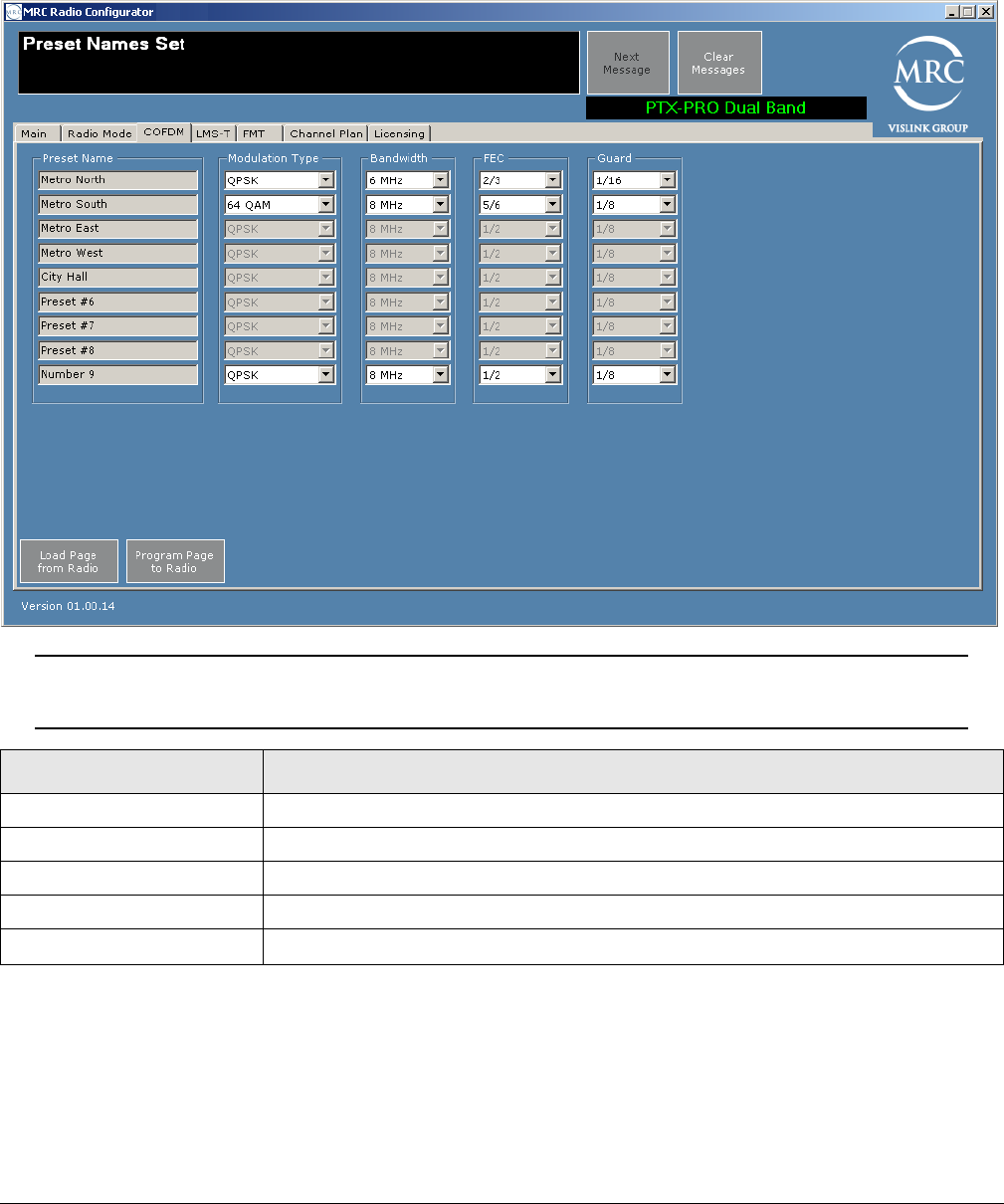
COFDM Tab
The COFDM (Coded Orthogonal Frequency Division Multiplexing) tab lets you specify the
following parameters.
Note Fields on the COFDM tab are active only for COFDM and ASI In operation
modes.
Load Page from Radio—To load parameters for this page from the PTX-PRO, click on this
button.
Program Page to Radio—To apply parameter modifications to the PTX-PRO, click on this
button.
Field Option
Preset Name Displays the name of the preset.
Modulation Type Select QPSK, 16 QAM, or 64 QAM.
Bandwidth Select 6 MHz, 7 MHz, or 8 MHz.
FEC Select 1/2, 2/3, 3/4, 5/6, or 7/8.
Guard Select 1/32, 1/16, 1/8, or 1/4.
3-10 Operating the PTX-PRO PTX-PRO User and Technical Manual
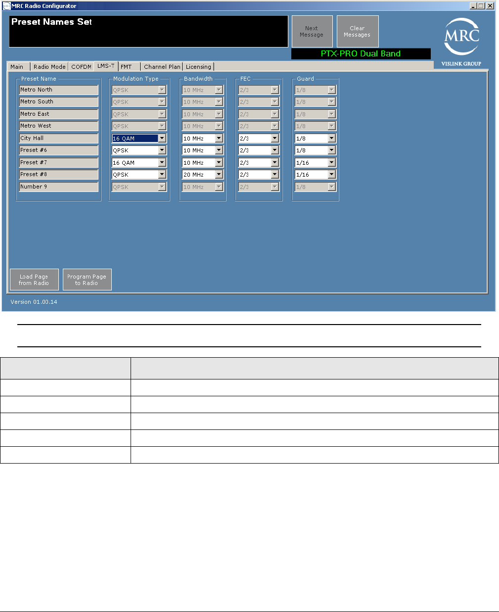
LMS-T Tab
The LMS-T (Link Modulation System - Terrestrial) tab is a proprietary algorithm system for
modulation. If you have this license, you can set the following parameters.
Note Fields on the LMS-T tab are active only for LMS-T operation mode.
Load Page from Radio—To load parameters for this page from the PTX-PRO, click on this
button.
Program Page to Radio—To apply parameter modifications to the PTX-PRO, click on this
button.
Field Option
Preset Name Displays the name of the preset.
Modulation Type Select QPSK, or 16 QAM.
Bandwidth Select 10 MHz, or 20 MHz.
FEC Select 2/3.
Guard Select 1/16, or 1/8.
Operating the PTX-PRO 3-11PTX-PRO User and Technical Manual
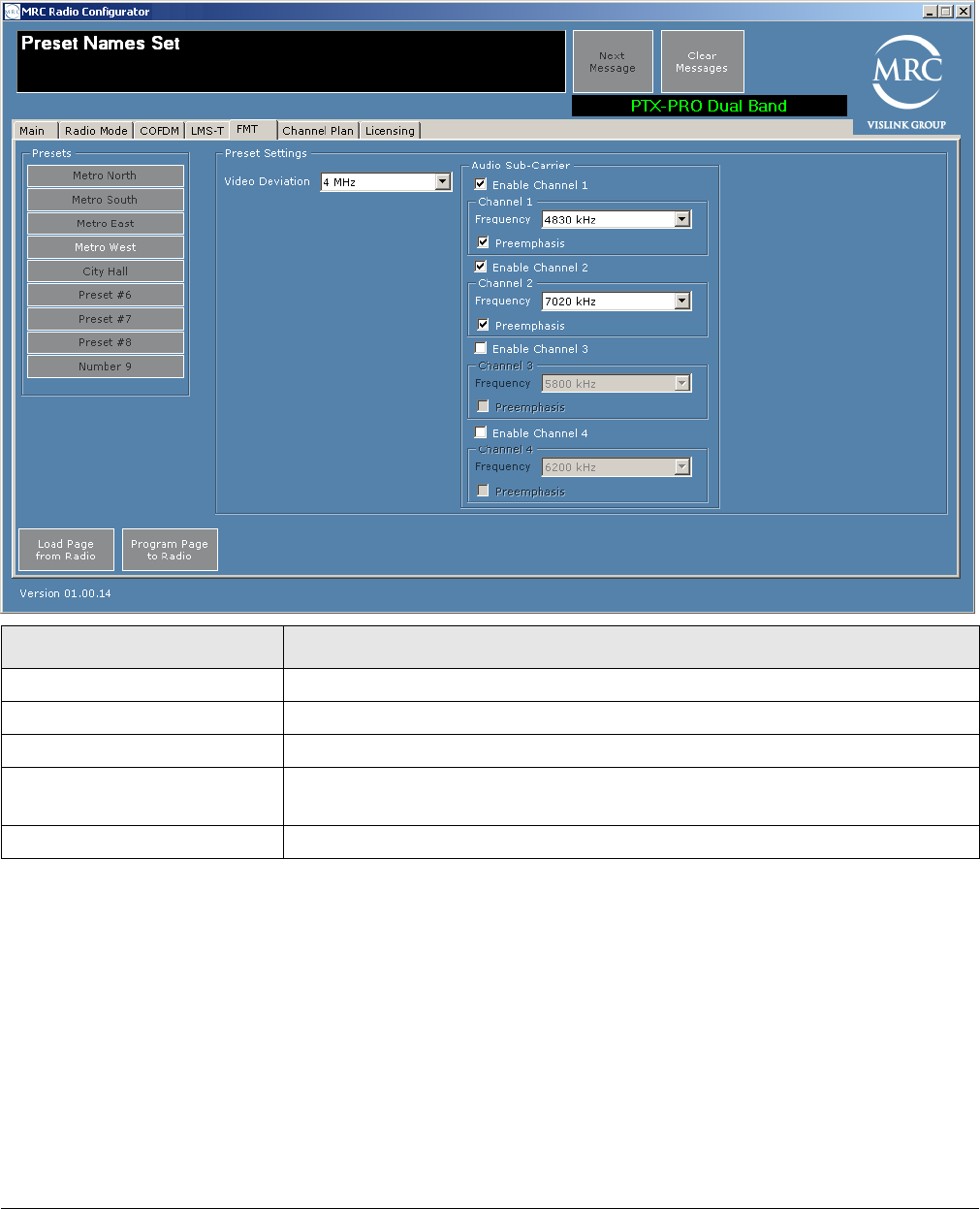
FMT Tab
The frequency modulation transmitter (FMT) tab lets you set the FMT parameters.
Load Page from Radio—To load parameters for this page from the PTX-PRO, click on this
button.
Program Page to Radio—To apply parameter modifications to the PTX-PRO, click on this
button.
Field Options
Presets Click on the preset to display the parameter values of that preset.
Video Deviation Choose 3 or 4 MHz.
Enable Channel 1 (2, 3, 4) Enable to access additional channel specifications.
Frequency When the channel is enabled, Choose one of the following frequencies:
4830, 5200, 5800, 6200, 6800, 7020, 7500, 8065, 8300, 8590.
Preemphasis Check to enable; leave blank to disable.
3-12 Operating the PTX-PRO PTX-PRO User and Technical Manual
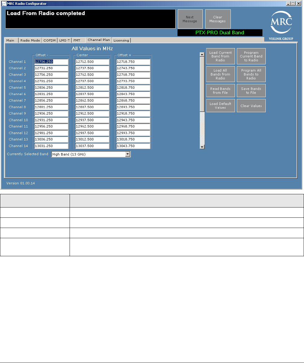
Channel Plan Tab
You can set up to a maximum of 22 channels for the PTX-PRO using channel plans with high
and low offsets at 13 GHz, and fewer channels based upon the frequency band radio deployed
(using the scroll bar).
Load Current Band From Radio—Apply the currently selected band to the Channel Plan
screen.
Program Current Band to Radio—Apply the currently selected band parameters to the
PTX-PRO.
Load All Bands from Radio—Apply the parameter settings from the PTX-PRO to the
Channel Plan screen.
Program All Bands to Radio—Apply the parameter settings to the PTX-PRO.
Read Bands from File—Click to select a previously saved file to load your channel plan.
Save Bands to File—Save the settings to a file that you can load on this or other PTX-PRO
radios.
Field Option
Offset – Specify the MHz values from your channel plan, or accept the default values.
Center Specify the MHz values from your channel plan, or accept the default values.
Offset + Specify the MHz values from your channel plan, or accept the default values.
Currently Selected
Band
If you have more than one band, select the one that you want to be current.

Operating the PTX-PRO 3-13PTX-PRO User and Technical Manual
Load Default Values—Click to load the default channel plan values.
Clear Values—Click to clear all channel plan values.
3-14 Operating the PTX-PRO PTX-PRO User and Technical Manual
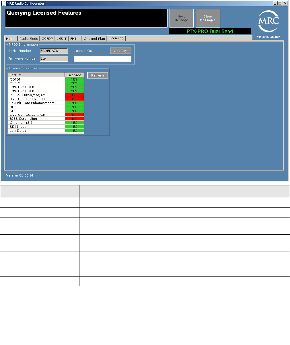
Licensing Tab
The Licensing Tab screen displays a list of features that your PTX-PRO has. If an item indicates
that a feature is not licensed, you can purchase and obtain it by contacting Vislink Customer
Support. Vislink supplies a license key that you enter to enable the licensed feature.
Field Option
Serial Number Displays the serial number of your PTX-PRO.
Firmware Number Displays the firmware number of your PTX-PRO.
License Key Enter the license key obtained from Vislink Customer Service then click
the Set Key button.
Set Key button Submits the licence key value; if valid, the corresponding license is
enabled.
Licensed Features box Displays the features you can use with your PTX-PRO. To obtain
additional features, contact Vislink Customer Service (see Section 4.1,
Getting Support for Your PTX-PRO on page 4-1).
Refresh Button Click this button to refresh the license list.

4
Troubleshooting 4-1PTX-PRO User and Technical Manual
Troubleshooting
This chapter describes how to troubleshoot your Transmitter (PTX-PRO).
4.1 Getting Support for Your PTX-PRO
You can contact the Vislink Technical Support staff as follows:
24-hour Worldwide Customer Support
E-mail: support@mrcbroadcast.com
Telephone: +1 978-671-5929 or
888-777-9221
Customer Service
E-mail: customerservice@mrcbroadcast.com
Telephone: +1 978-671-5700 Press 3
Monday-Friday, 8AM-5PM EST USA
When you contact Technical Support, include the following information:
• Model number and serial number (located on a label on the bottom of each unit).
• Approximate purchase date.
4.1.1 Replacement Parts
The external cables and connectors for the PTX-PRO are listed in the following table. If you
need something that is not listed, ask your Sales Representative or consult the factory.
Part Description
AC Power Cable (120 VAC) Connects AC power to the PTX-PRO. Connectors on both ends.
AC Power Cable (240 VAC) Connects AC power to the PTX-PRO. Connectors on one end only.
DC Power Cable
(+11.0 to +36.0 VDC)
Connects DC power to the PTX-PRO. Connector on one end only.
Audio Input Cable Provides input to PTX-PRO AUDIO 1 and 2 connectors from 2 XLR
connectors. See Section A.3, Audio Connections on page A-3.
Null Modem Cable Connects PTX-PRO RS-232 connector to PC RS-232 connector.
For programming and monitoring data only. Section A.5, Data
Connections on page A-5.
Audio Input Connector Connects to PTX-PRO AUDIO 3 & 4 connector for Audio 3 and 4
inputs. Section A.5, Data Connections on page A-5.
Multipurpose Data Cable Connects to PTX-PRO RS 232 connector to monitor Wayside and
Radio data.
RF Coaxial Cable Connects PTX-PRO RF output connector to antenna.
Power Input Connector Connector only - Mates with PTX-PRO PWR connector.
Audio Input XLR Connector Connector only - Mates with PTX-PRO AUDIO 1 or 2 connectors.

4-2 Troubleshooting PTX-PRO User and Technical Manual
The mounting hardware for the PTX-PRO is listed in the following table.
4.1.2 Supported Repairs
There are no supported field repairs to the PTX-PRO. Return the unit for factory repair.
CAUTION If you attempt field repair, you risk damaging your equipment. If
your equipment is under warranty, you may also affect your warranty
coverage. The PTX-PRO requires specialized test equipment and
software to calibrate operating characteristics after repair.
4.2 Addressing General Problems
Part Description
Antenna Lock Plate Attaches an MRC antenna directly to PTX-PRO RF output connector.
Quick Release Provides quick release mounting of the PTX-PRO on an MRC tripod
Problem Possible Cause Action
PWR LED on
PTX-PRO is off
when PWR switch is
set to on ( I ).
Missing input power. • Make sure power cable is connected properly.
• Make sure power source on.
• Check input power voltage.
• Check both AC and DC power fuses.
PWR LED on
PTX-PRO is amber.
PTX-PRO is
indicating a Minor
Alarm.
• Check all Monitor Screens on PTX-PRO display.
See Section 4.3, Addressing Display Error
Messages on page 4-3.
• Check Error Code Screen on PTX-PRO display.
See Section 4.4, Addressing Video Problems on
page 4-3.
PWR LED on
PTX-PRO is red.
PTX-PRO is
indicating a Major
Alarm.
• TURN OFF POWER and call for service.
Test Tone is on and
cannot be turned off
from the radio.
Audio must be set
from the Configurator
(and cannot be set
from the radio).
Configurator setup is
incorrect.
• Before programming the radio from the
configurator, click Load all Settings, which will
set the audio automatically from the radio. See
Section 3.5, Configuring the PTX-PRO With a PC
on page 3-4
•Set Audio Input to Analog, SDI EMB, or AES
EBU, or set Audio Type to OFF. See MPEG Tab
on page 3-7.

Troubleshooting 4-3PTX-PRO User and Technical Manual
4.3 Addressing Display Error Messages
Messages on the PTX-PRO screen alert you to problems. The following table suggests what to
do if they appear.
4.4 Addressing Video Problems
Message Meaning Action
Not On Chnl Channel frequencies
defined in the
Channel Plan for that
band are not being
recognized.
• Change the channel.
• Use Configurator software to check that the Channel
Plan is correct.
• Verify Channel Plan matches the transmitter settings.
• If message persists even when operating on a
frequency that matches the channel plan, unit may
have suffered internal failure.
No Video The PTX-PRO is
unable to lock onto
video signal.
• Check for correct operation mode.
• Check cable connections to SIGNAL INPUT and
SDI/ASI INPUT connectors.
• Use Configurator software to check settings.
• If message persists, unit may have suffered internal
failure.
Problem Possible Cause Action
No video. Problem with video
source or cabling
• Check video source and cabling.
Transmitter and
Receiver compatibility
problems
• Verify Transmitter and Receiver are both operating in the
same digital mode.
• Verify Transmitter and Receiver are both operating on the
same frequency. If frequency offsets are used, verify
offsets are identical between Transmitter and Receiver.
Video source
configuration problem
• Verify PTX-PRO front panel settings match video source
inputs.

4-4 Troubleshooting PTX-PRO User and Technical Manual
4.5 Addressing Error Codes
The following table describes the error codes and what to do if they appear.
Error
Code Meaning Action
E000 Error Summary • Provides error summary.
E001 Message ID • Displayed when a status message times out.
E020 IF Fault • Verify condition of cable connections.
E021 RF Fault • Verify condition of cable connections.
E080 Communication Failure with the
COFDM/MPEG Module
• Verify condition of cable connections.
Parameter Errors
(Some internal parameter is outside of allowable limits.)
Note: An additional number on the status indicates that the value is too low (4) or too high (8).
E030 2.048 Volt Reference Error • Check for Error Codes related to power - E03A
thru E03E.
• Verify cable connectors are fully mated and verify
cable and connectors are undamaged.
• Make sure power cable is connected properly.
E031 5.5 Volt Reference Error
E032 7 Volt Line Error
E033 11 Volt Line Error
E034 Temperature Error • Check PTX-PRO to be sure it is not too close to
sources of heat. Relocate PTX-PRO, if possible.
• Verify PTX-PRO has room around it for air
circulation. Move objects preventing air flow.
E038 50 Ohm Coax Current Error • Contact technical staff.
E039 50 Ohm Coax Voltage Error
E03A 50 Ohm Coax Power Error
E03B Circular Connector Current Error • Verify all power cables are properly connected and
are not damaged.
• Verify correct input power is being applied to the
PTX-PRO.
E03C Circular Connector Voltage Error
E03D Circular Connector Power Error
E03E DC Bus Error • Contact technical staff.
E03F Fan Fault • Contact technical staff.

Troubleshooting 4-5PTX-PRO User and Technical Manual
4.6 Addressing Configurator Problems
The following table describes the MRC Radio Configurator errors and what to do if they appear.
Error Possible Cause Suggested Action
Connection failed on
[COM port name]
PTX-PRO system power is off. Turn PTX-PRO system power on.
RS-232 cable is disconnected. Connect cable. Ensure connectors are
fully seated on both ends.
RS-232 cable is defective. Replace cable.
Installed PTX-PRO hardware is
defective.
Contact Technical Support.
Querying [Setting]
failed...
Problem with RS-232
communication.
Try again. If error still appears, turn off
PTX-PRO system power, close the
Configurator, then turn on PTX-PRO
power and restart Configurator.
RS-232 cable is disconnected. Connect cable. Be sure connectors on
both ends are fully seated.
RS-232 cable is defective. Replace cable.
Installed PTX-PRO hardware is
defective.
Contact Technical Support.
Configuration File
Corrupt
OR
Unable to Open
Configuration File
Unable to read data stored in
file chosen.
Select a different configuration file.
File damaged. Re-create configuration and save it with a
different file name.
Problem with PC or its disk
drive.
Contact your PC service provider.
Configurator won’t
install on PC.
Previous version of MRC Radio
Configurator already installed.
Uninstall previous version using the “Add/
Remove Programs” function in Microsoft
Windows Control Panel.
PC does not meet System
Requirements.
See Section 2.5, Installing Configurator
Software on page 2-8.
CD damaged. Contact Technical Support.
Problem with PC or its disk
drive.
Contact your PC service provider.
Configurator crashes
when trying to run.
AND / OR
Get “Runtime Error”
message.
Program files damaged. Use the “Add/Remove Programs”
function in Microsoft Windows Control
Panel to uninstall the Configurator, then
reinstall it.
Problem with PC or its disk
drive.
Contact your PC service provider.

4-6 Troubleshooting PTX-PRO User and Technical Manual
A
PTX-PRO Specifications A-1PTX-PRO User and Technical Manual
PTX-PRO Specifications
This appendix contains specifications for your PTX-PRO Transmitter (PTX-PRO).
A.1 PTX-PRO Physical Specifications
Dimensions: 9.3” x 4.0” x 12.0”
Weight: 19.85 lbs (9.0 Kg).
Operating temperature: –20°C to +50°C
A.2 Power Connections
Check the electrical supply to be sure it can provide all the power needed at the site without
overloading. Power ratings for equipment can be found on a rating plate, usually on the rear
panel. If necessary, consult a licensed electrician.
A.2.1 Power Supply and Distribution
The PTX-PRO PWR (power) connector is located on the front panel. The mating connector that
plugs into this panel connector is as follows.
Manufacturer: ITT Cannon
Part Number: KPT06F14-12SX
Manufacturer: Amphenol
Part Number: PT06E14-12SX
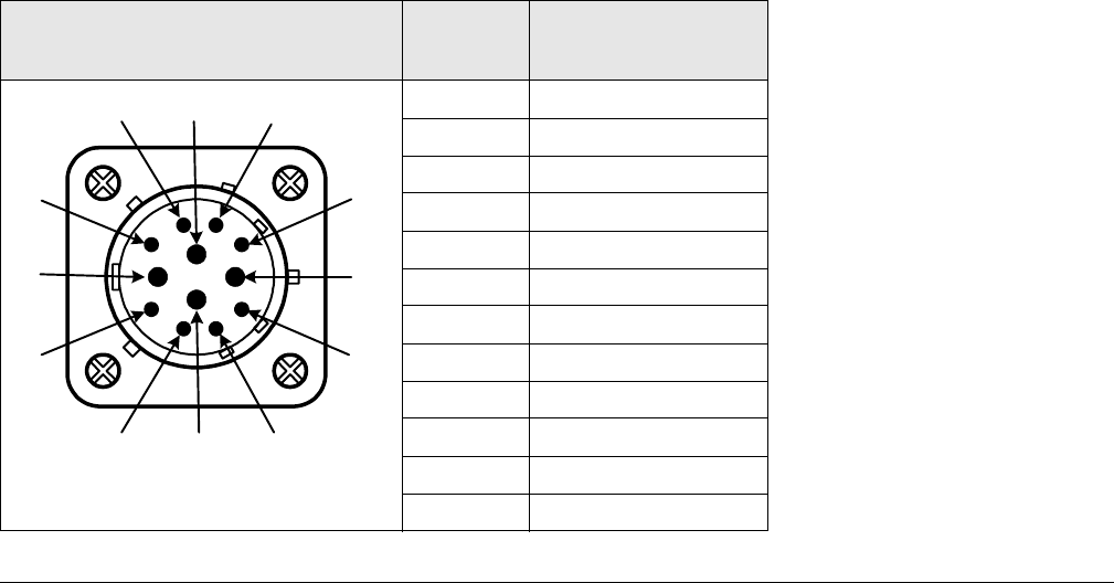
The following table shows the pin-outs on the front panel 12-pin PWR connector.
Connector Information Pin-Out Signal
Description
A 90 to 264 VAC
BN/C
C Neutral
DN/C
EN/C
FN/C
GN/C
HN/C
J DC (+)
K DC (-)
L AC Ground / DC (-)
M DC (+)
A
B
C
D
E
F
G
HJ
K
L
M
A-2 PTX-PRO Specifications PTX-PRO User and Technical Manual
The PTX-PRO universal AC/DC power supply can operate on either external AC or DC power
sources. Power cable assemblies are available from MRC for the PTX-PRO based on the
power to be used.
Note If it is necessary to fabricate your own AC or DC power cable assembly, 20
AWG stranded wire is recommended for lengths up to 10 feet (3 M). Use one
wire per connector contact. Consult the factory if you need longer cabling.
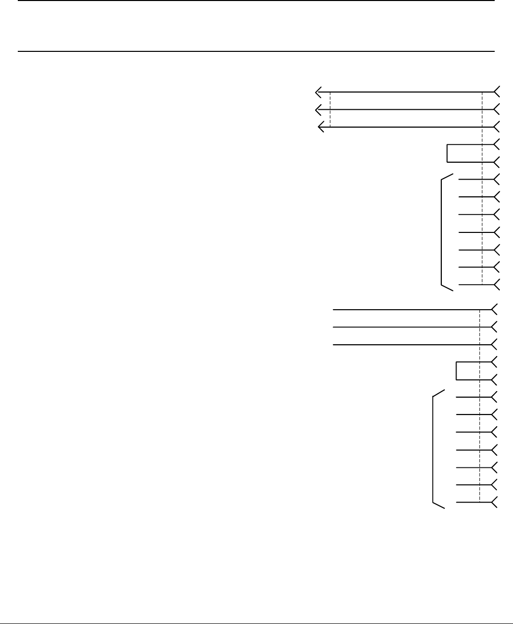
AC Power Cable Assemblies
Prefabricated AC Power Cable
Assemblies are available from MRC to
connect the PTX-PRO PWR connector
to either 120 VAC or 240 VAC.
The AC Power Cable Assemblies are 6.0
ft. (1.8 m) long. The 120 VAC Power
Cable Assembly comes complete with
power connectors on both ends. The
following figure shows the wiring
diagram of the 120 VAC Power Cable
Assembly.
The 240 VAC Power Cable Assembly
comes with a power connector on one
end only. The user must provide the
input power connector for the 240 VAC
version of the Power Cable Assembly.
The following figure shows the wiring
diagram of the 240 VAC Power Cable
Assembly.
White
Black
Green
C
A
L
E
F
B
D
G
H
J
K
M
NC
120 VAC
Neutral
Ground
White
Black
Green
C
A
L
E
F
B
D
G
H
J
K
M
NC
Neutral
240 VAC
Ground
PTX-PRO Specifications A-3PTX-PRO User and Technical Manual
DC Power Cable Assembly
A prefabricated DC Power Cable
Assembly is available from MRC to
connect the PTX-PRO PWR connector
to a DC power source.
The DC Power Cable Assembly is 10 ft.
(3 m) long. The DC Power Cable
Assembly comes with a power connector
on one end only. The following figure
shows the wiring diagram of the DC
Power Cable Assembly.
A.3 Audio Connections
The PTX-PRO can provide analog or digital audio inputs. All audio inputs are available at either
the front or rear panel audio connectors.
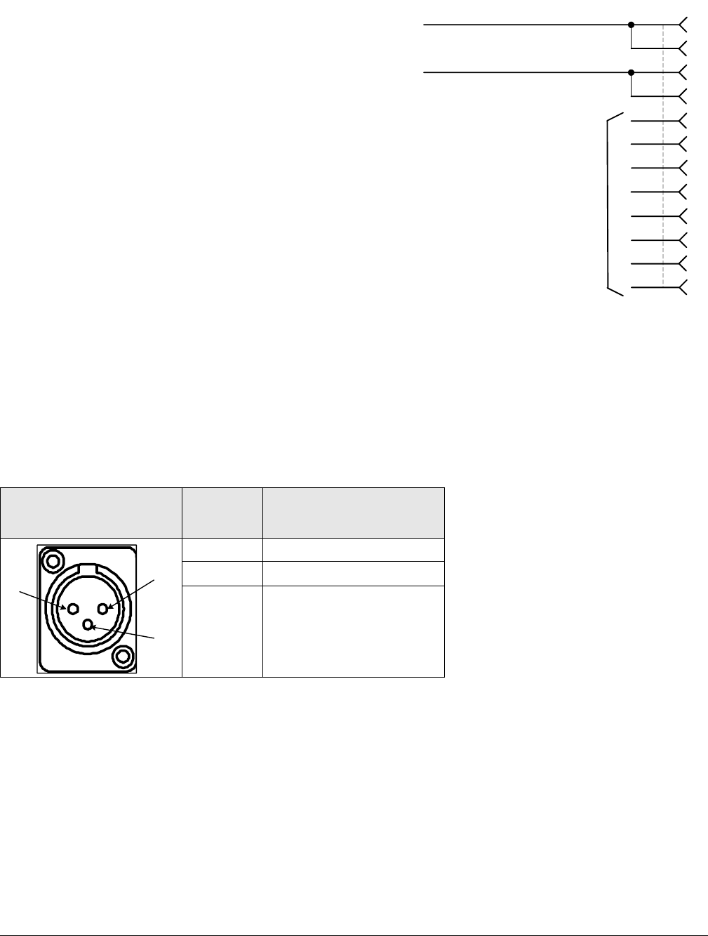
A.3.1 Front Panel Audio Connections
Front panel AUDIO 1/L1 and AUDIO 2 XLR/R1 connectors are used for MPEG Audio A inputs
or analog subcarriers 1 and 2. Connector pin-outs are shown in the following table.
Connector
Information Pin-Out Signal Description
1 Ground
2Live (+)
3 Return (–)
Black
Red
C
A
L
E
F
B
D
G
H
J
K
M
NC
DC Negative
DC Positive
1
2
3
A-4 PTX-PRO Specifications PTX-PRO User and Technical Manual
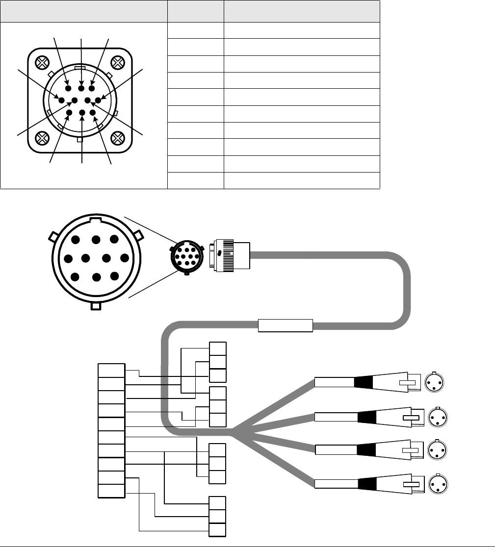
A.3.2 Rear Panel Audio Connections
The rear panel AUDIO 3 & 4 / AES-EBU connector is used for MPEG Audio B inputs or analog
subcarriers 3 and 4. The mating connector is an Amphenol (MS3116F12-10S) or ITT Cannon
(KPT06F12-10S). Rear panel AUDIO 3 & 4 / AES-EBU 10-PIN male connector pin-outs are
shown in the following table. A prefabricated cable assembly (as shown in the following figure)
splits the audio connections into two separate cables with XLR connectors. One cable assembly
is included with each PTX-PRO ordered.
Connector Information Pin-Out Signal Description
A DIGITAL 1 CH1 +
B DIGITAL 1/2 GND
C DIGITAL 1 CH1 –
D DIGITAL 2 CH2 +
E DIGITAL 2 CH2 –
F ANALOG 3 LEFT CH2 –
G ANALOG 3/4 COM
H ANALOG 3 LEFT CH2 +
J ANALOG 4 RIGHT CH2 –
K ANALOG 4 RIGHT CH2 +
AB
C
D
EF
G
H
J
K
RoHS
907471-1 REV F
AV040910-2408
1
2
3
1
2
3
E
A
B
C
D
G
H
J
K
F
Not Used
Not Used
Not Used
BLK
SHIELD
RED
BLK
RED
Not Used
Not Used
Digital AUDIO 1
Digital AUDIO 2
.
A
B
C
D
E
F
G
H
JK
DIGITAL AUDIO 1
DIGITAL AUDIO 2
AUDIO 3/L2
AUDIO 4/R2
AUDIO 3/L2
AUDIO 4/R2
1
2
3
1
2
3
.12
3
12
3
12
3
12
3
PTX-PRO Specifications A-5PTX-PRO User and Technical Manual
The PTX-PRO provides a maximum of four audio circuits. Each audio circuit is a 3-wire
balanced circuit capable of carrying one tone or voice signal. An audio circuit can carry one
analog balanced channel or two digital AES/EBU channels.
A.3.3 MPEG Audio input
MPEG audio circuits must be configured in pairs with the MRC Radio Configurator software:
•Audio 1 - LEFT/RIGHT or Digital AES/EBU.
•Audio 2 - LEFT/RIGHT or Digital AES/EBU.
A.3.4 AES/EBU Audio input
The PTX-PRO only provides digital audio when operating in digital mode.
In digital mode, the PTX-PRO receives a digital signal and routes the data to the MPEG
decoder and then to the COFDM demodulator. The PTX-PRO audio switching circuitry
connects the input of the MPEG decoder to the AUDIO connector.
When configured for digital audio input (AES/EBU), the MPEG decoder provides two paired
channels of digital data (+ and –), or four individual channels. All four circuits are balanced
inputs, with each pair (+ and –) sharing one ground.
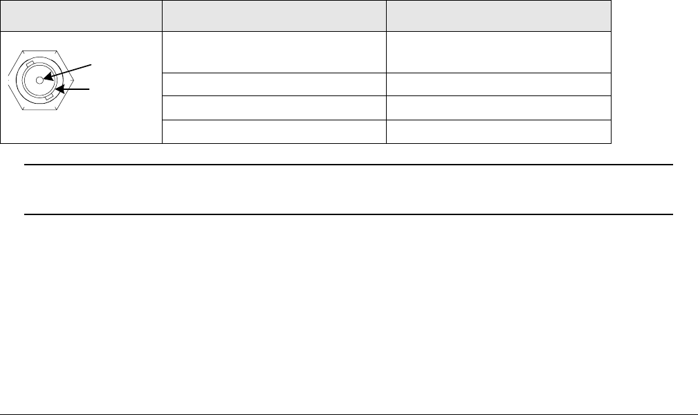
A.4 Video Connections
The PTX-PRO provides several video options on the front panel, using 75 Ohm BNC
connectors, as described in the following table and in Section 1.1, Front Panel Controls,
Indicators, and Connectors on page 1-2.
Note If your PTX-PRO has only 3 BNC connectors on the front panel, your SDI and
ASI share the same connector.
A.5 Data Connections
The PTX-PRO has an RS-232 data connector on the rear panel for the following purposes:
• Remote Control using a STRATA RX Remote Control Panel
• Radio Programming using a PC
• Wayside Data communication.
Operation Mode Connector Signals
Signal Input NTSC/PAL (525/625) or
70 MHz IF
Monitor (output) 70 MHz
SDI/SD/HD (input) SDI (525/625) or HD-SDI
ASI INPUT ASI input
Signal
Ground
A-6 PTX-PRO Specifications PTX-PRO User and Technical Manual
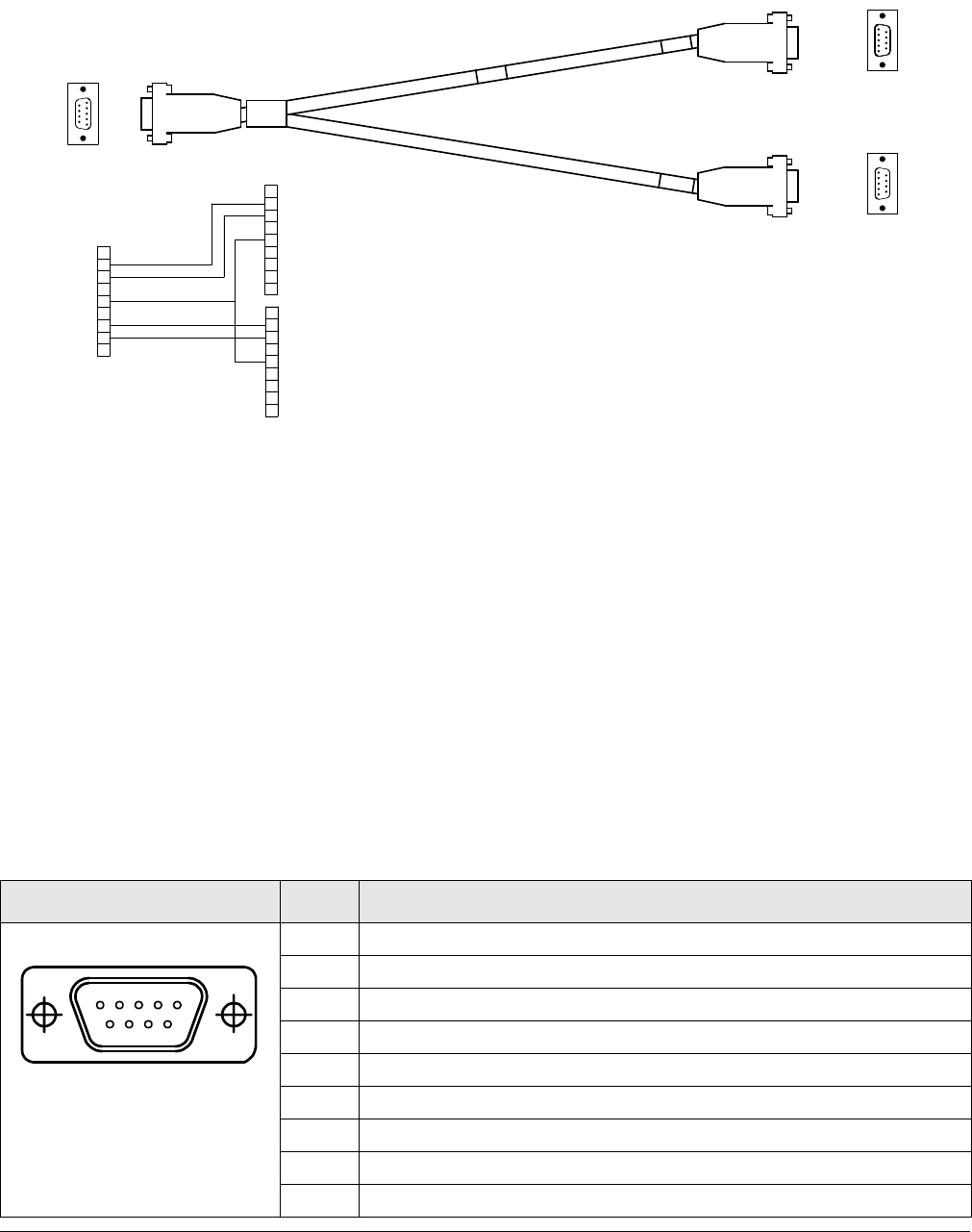
To access both radio and Wayside data, connect the DB-9 female RS-232 connector of the
Multipurpose Data Cable (shown) to the PTX-PRO RS-232 connector.
The Multipurpose Data Cable contains two DB-9 female connectors and one DB-9 male
connector and contains band markers indicating connections to HOST, WAYSIDE, and RS-232
connectors.
•The HOST DB-9 male connector is a Data Terminal Equipment (DTE) device that
connects to a PC. When you connect the Multipurpose Data Cable to a HOST DB-9 male
DTE device, you also must connect a null modem between the DTE device and the
HOST male connector. If the HOST connector is connected to a DCE device, you cannot
use a null modem cable, but you will need a straight pin-to-pin extension cable.
•The WAYSIDE DB-9 female connector is a Data Communication Equipment (DCE)
device connector that connects to a modem, GPS, etc. When you connect the
Multipurpose Data Cable to a WAYSIDE DB-9 female DCE device, you also must
connect a null modem between the DCE device and the WAYSIDE female connector. If
the WAYSIDE connector is connected to a DTE device, you cannot use a null modem
cable, but you will need a straight pin-to-pin extension cable.
The following table shows programming connections using the Multipurpose Data Cable.
Connector Pin Function
1N/C
2 Receive Data
3 Transmit Data
4N/C
5GND
6N/C
7 Transmit Data (sends Wayside data to an external device)
8 Receive Data (carries Wayside data from an external device)
9N/C
9
9
5
5
1
1
6
6
1
1
6
6
9
9
5
5
5
5
1
1
6
6
9
9
RED
RED
WHT
WHT
5
5
7
7
6
6
4
4
3
3
2
2
1
1
8
8
9
9
9
9
8
8
1
1
2
2
3
3
4
4
6
6
7
7
5
5
9
9
8
8
1
1
2
2
3
3
4
4
6
6
7
7
5
5
WHT
WHT
RED
RED
BLK
BLK
RADIO (M)
RADIO (M)
WAYSIDE (F)
WAYSIDE (F)
RADIO (M)
RADIO (M)
WAYSIDE (F)
WAYSIDE (F)
RADIO/WAYSIDE
RADIO/WAYSIDE
(F)
(F)
RADIO/
RADIO/
WAYSIDE (F)
WAYSIDE (F)
15
69
PTX-PRO Specifications A-7PTX-PRO User and Technical Manual
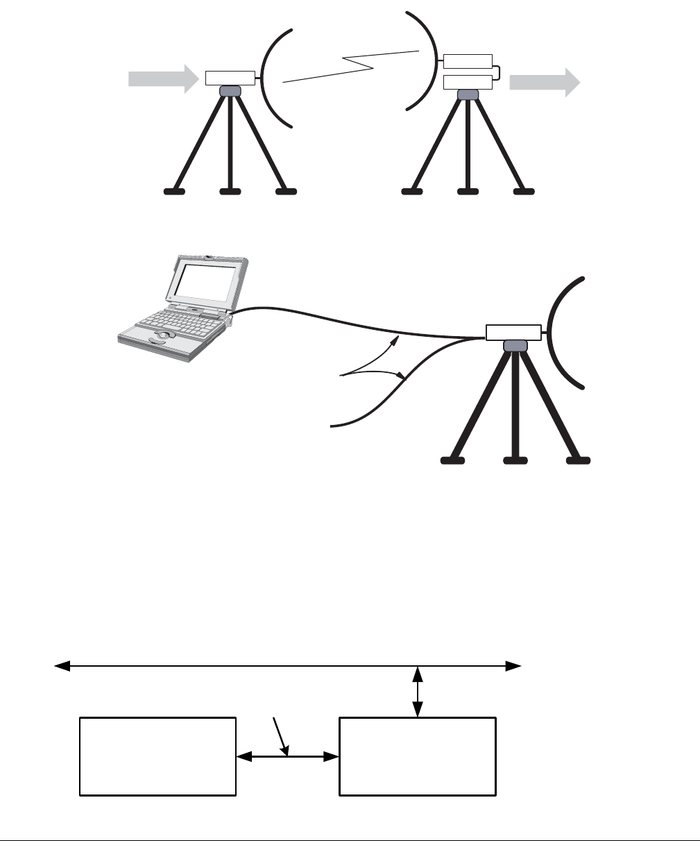
A.5.1 Wayside Data
The Wayside channel is a simplex data channel receiving data at the PTX-PRO from a
transmitter system. The PTX-PRO outputs data using connections to the serial port through a
Multipurpose Data Cable.
Connect the Wayside channel to the serial port using a Serial/Wayside Multipurpose Data Cable
as shown in the following figure.
The cable connects to the RS-232 connector on the PTX-PRO and has connections for both the
Wayside channel and the PC required for use with the MRC Radio Configurator software.
A.5.2 Networking
You can connect the RS-232 connector on the PTX-PRO to a network to monitor and program
the PTX-PRO from a remote location. To connect the PTX-PRO to a network, you will need the
following items.
TX
RX
WAYSIDE WAYSIDE
TX or RX
RS-232 Wayside
Data Channel
Signal (i.e.,
GPS Data)
Multipurpose
Data Cable
RS-232
Serial
Connection to
PC or Laptop
PTX-PRO TX
System
UDS-10 Device
Server (or
Equivalent)
Interface
Cable
Ethernet LAN
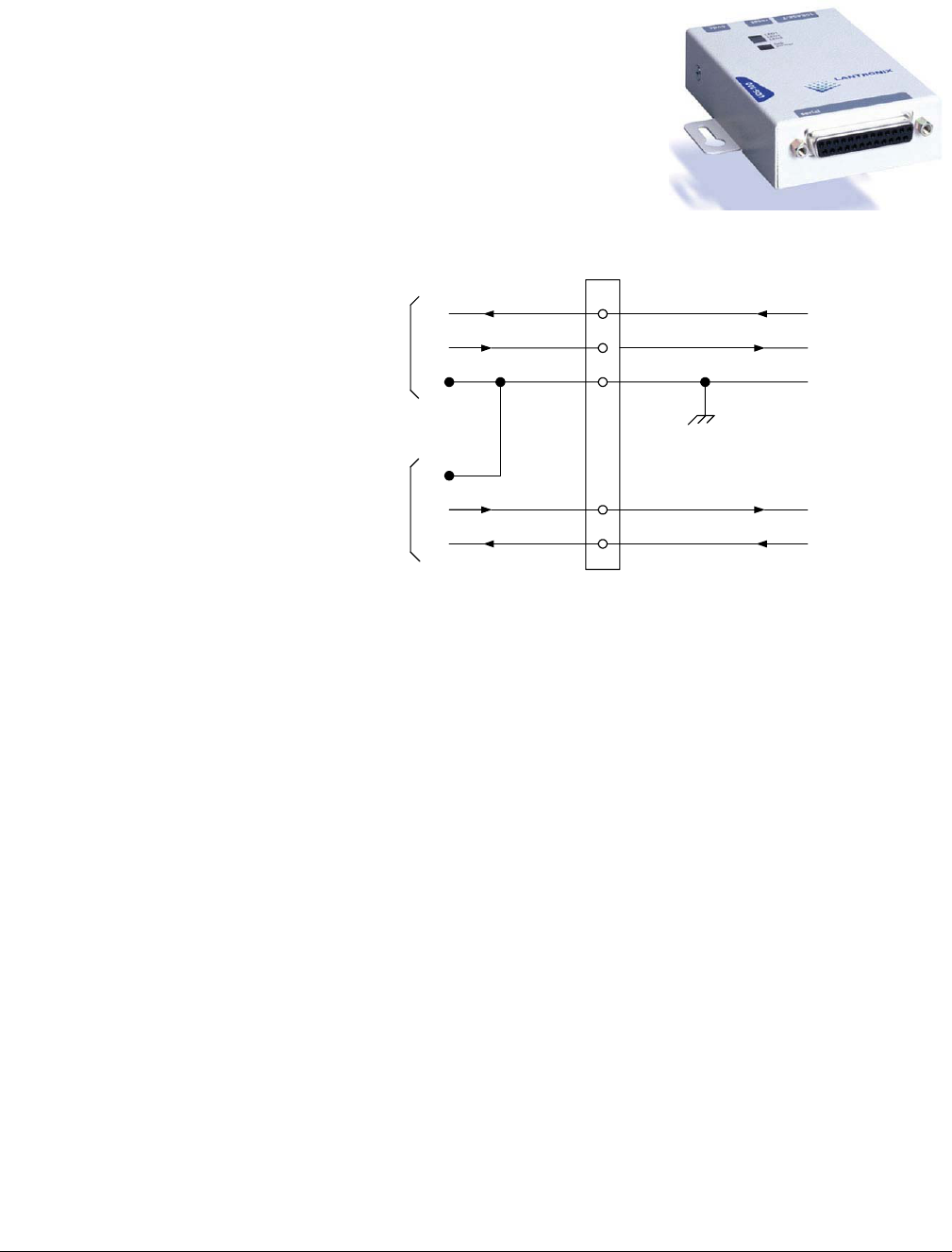
A-8 PTX-PRO Specifications PTX-PRO User and Technical Manual
• Device Server
Also called Serial-to-Ethernet converters, the device
servers take serial RS-232 data and convert it to the
format needed for an Ethernet network.
You can use a Lantronix UDS-10 because it accepts data
via a DB-25 connector, and connects to the network via an
RJ-45 connector.
• Interface Cable
This cable connects to
the PTX-PRO data
connector (DB-9) on one
end and connect to the
device server on the
other (for example, a
DB-25 connector in the
case of the UDS-10).
This is a custom cable
which you will have to
fabricate.
2
3
5
7
8
RD
TD
SG
SG
TD
RD
Radio
Data
Wayside
Data
Signal Ground
Receive Data
Transmit Data
Wayside Data to External
Device
Wayside Data from External
Device (Not Used)
Transmit Wayside
Data
Receive Wayside
Data
To PTX-PRO RS-232
Connector DB-9 (Male)

Index-1PTX-PRO User and Technical Manual
Index
Numerics
13 GHz channel plan 1-6
2 GHz channel plan 1-5
7 GHz channel plan 1-5
A
AC power cable assembly A-2
AC power supply 1-1
AC/DC power connector
connector
AC/DC 1-3
AES/EBU audio input A-5
alphanumeric display 1-2, 3-1
Analog IF mode 3-2
antenna lock plate 2-7
ASI In mode 3-2
ASI INPUT 1-3
audio
AES/EBU input A-5
digital A-5
MPEG input A-5
outputs A-3
C
calculating MPE 2-2
CHAN Switch 1-2
changing a preset 3-3
channel plan, 13 GHz 1-6
channel plan, 2 GHz 1-5
chassis ground A-B
COFDM
parameters 3-9
COFDM mode 3-2
color bar, setting 3-3
configurator
installing 2-8
PC requirements 2-8
configure 3-3
configure with a PC 3-4
connector
audio A-4
AUDIO 1 and AUDIO 2 XLR A-3
AUDIO 3 & 4 / AES-EBU A-4
mating power connector A-1
PWR (power) connector A-1
rear panel 1-3
RF output 1-4
D
damage (reporting) 2-1
data cable, multipurpose A-7
data connections A-5
networking A-7
Wayside data A-7
DC power cable assembly A-3
DC power supply 1-1
digital audio A-5
dovetail adapter plate 2-5
dual band switch 1-2
E
earth ground A-B
error codes 4-4
Ext. IF mode 3-2
F
FMT 3-11
frame ground A-B
G
grounding 2-4
H
HD video input, changing 3-3
I
installing 2-1
unpacking 2-1
ISO certification A-B
L
licensing 3-14
LMS-T 3-10
LMS-T mode 3-2
M
manual configuration 3-3
monitoring operations 3-2
mounting hardware 4-2

Index-2 PTX-PRO User and Technical Manual
MPE, calculating 2-2
MPEG audio input A-5
MPEG/CODFM module 1-1
MRC Radio Configurator, using 3-4
MRC tripod 2-5
multipurpose data cable A-7
N
networking A-7
O
OFFSET Switch 1-2
P
parameter
channel plan 3-12
CODFM 3-9
FMT 3-11
LMS-T 3-10
loading 3-5
radio mode 3-6
saving 3-5
parts
external cables and connectors 4-1
mounting hardware 4-2
portable applications 2-5
antenna lock plate 2-7
dovetail adapter plate 2-5
MRC tripod 2-5
non-MRC tripod 2-5, 2-6
quick release mount 2-5
power
cable assemblies A-2
distribution, AC or DC A-2
ratings A-1
requirements 1-1
supply and distribution A-1
powering up 3-1
preset
changing 3-3
changing names 3-5
proprietary notice A-B
protective earth ground A-B
PWR LED 1-2
Q
quick release mount 2-5
R
radio mode parameters 3-6
related documents A-B
replacement parts
external cables and connectors 4-1
mounting hardware 4-2
reporting damage 2-1
RF output connector 1-4
RF power hazard 2-2
S
safety requirements A-B
SD video input, changing 3-3
SDI/HD/SD 1-3
signal connections A-5
SIGNAL INPUT 1-3
symbols on equipment
danger A-B
earth ground A-B
electric shock A-B
electrostatic discharge A-B
frame or chassis ground A-B
fuse A-B
T
transmitter attenuation, setting 3-3
troubleshooting
error codes 4-4
general problems 4-2
video 4-3
U
unpacking 2-1
unpacking the equipment 2-1
V
video
changing HD input 3-3
changing SD input 3-3
connections A-5
input mode, changing 3-3
troubleshooting 4-3
W
Wayside data connection A-7