Microwave Radio Communications STATXU064T1CK STRATA Mobile Transmitter STATXU064T1CK User Manual Op Guide
Microwave Radio Communications LLC STRATA Mobile Transmitter STATXU064T1CK Op Guide
Manual
STRATA TX System
Operator’s Guide
Analog + Digital Portable
3.4 to 13.25 GHz Microwave
Transmitter
Manual Part No. 400504-1
Rev. C February 2007

iSTRATA TX Operator’s Guide/Tech Ref Manual
Note To User - RF Exposure
MPE Calculation
RF Exposure
Microwave Radio Communications (MRC) provides this warning
for safety purposes with the intent to inform the user of the
potential hazard to RF exposure. The following guidelines for
safe operation were derived from OET bulletin 65, August 1997,
as recommended by the Federal Communications Commission
(FCC).
The 6.4 - 7.125 GHz STRATA transmitter is a mobile transmitter
designed to provide services to broadcast ENG users under
CFR 74 subpart F and 74.601 TV pickup stations. This unit,
operated without an antenna, will not create RF energy
exceeding 1.0 mW/cm2, the FCC limit for exposure. Once
connected to an antenna, the potential for harmful exposure will
be greatly enhanced.
In this situation, a certain distance from the radiator is to be
maintained. Calculations need to be performed to understand
what that safe margin for exposure is. This is known as the
Maximum Permissible Exposure (MPE) limit.
Calculations provided are for common antennas often utilized in
the ENG environment. The following formula used is that
suggested by OET 65.
Calculating MPE
EIRP = P * (10 ^ (G / 10)) = (antilog of G/10) * P
P = RF power delivered to the antenna in mW
G = Power gain of the antenna in the direction of interest relative
to an isotropic radiator
R = distance to the center of radiation of the antenna in
centimeters
S = MPE in mW/cm² (milliwatts per square centimeters)
Conversions
dBi to numeric gain = Antilog (dBi/10)
Feet to centimeters = Feet * 30.48
Centimeters to Feet = cm * .0328
4 π = 12.57
User Input
RF power delivered to the antenna = Watts
Antenna gain (referenced to isotropic antenna) = dBi
Distance from the center of radiation = Feet
Calculation steps:
1. [P] RF power input. Convert watts to milliwatts = Watts *
1000
2. [G] Antenna gain dBi. Convert to numeric gain = Antilog
(dBi/10)
3. [EIRP] Multiply P * G
4. [R] Convert centimeters to feet = Centimeters * .0328
5. Square R
PG (or EIRP)
S= 4πR2
iiSTRATA TX Operator’s Guide/Tech Ref Manual
6. Multiply R² * 4π
7. [S] Divide (R² * 4π) into EIRP
S = Power Density in milliwatts per square centimeters. Note:
At frequencies above 1500 MHz, S must not be greater than 1
Reference
FCC OET Bulletin 65, August 1997 - Evaluating Compliance with
FCC Guidelines for Human Exposure to Radio Frequency
Electromagnetic Fields
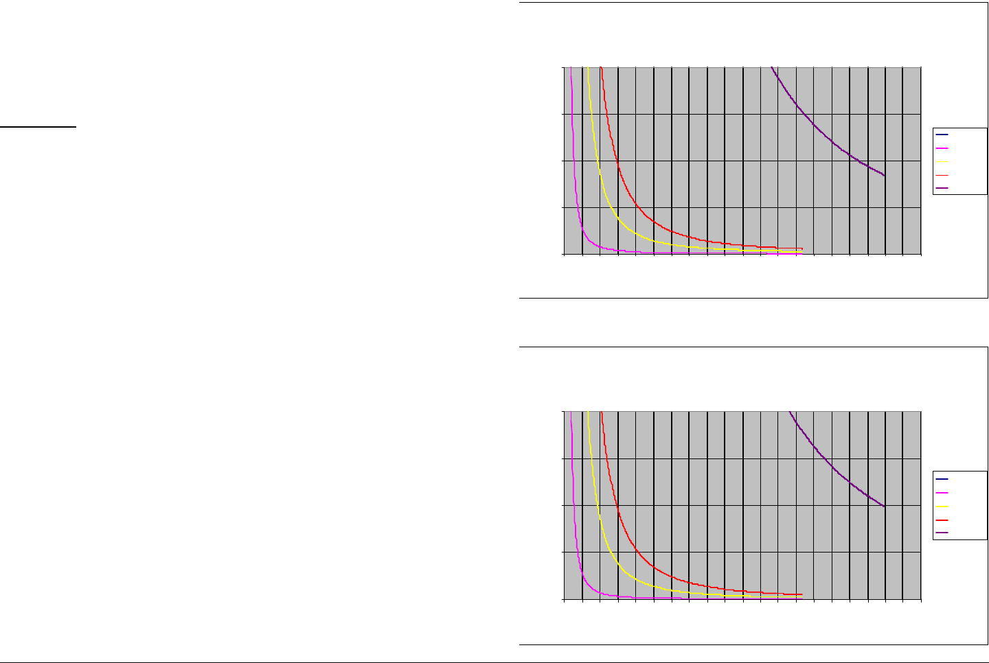
Figure 1 and Figure 2 show the maximum exposure distance for
various antennas. One plot provides the maximum permissible
output of the STRATA transmitter for analog modulation, and the
other plot for digital modulation.
MRC, in accordance with the requirements set forth by the FCC,
provides this information as a guide to the user. It is assumed
that the users of this equipment are licensed and qualified to
operate the equipment per the guidelines and recommendations
contained within the product user guides and in accordance with
any FCC rules that may apply.
Figure 1: Analog Modulation
Figure 2: Digital Modulation
Estimated Permissible Exposure
@ 2.7 Watts Digital RF Power
for STRATA 6.425 - 6.525 and 6.8875 - 7.1255 GHz.
0
0.5
1
1.5
2
0 2 4 6 8 10121416182022242628303234363840
Distance in Feet
Power Density (mW/cm^2)
0dBi
5dBi
16dBi
20dBi
35.7dBi
Estimated Permissible Exposure
@ 4.0 Watts Analog RF Power
for STRATA 6.425 - 6.525 and 6.8875 - 7.1255 GHz.
0
0.5
1
1.5
2
0 2 4 6 8 10121416182022242628303234363840
Distance in Feet
Power Density (mW/cm^2)
0dBi
5dBi
16dBi
20dBi
35.7dBi

iiiSTRATA TX Operator’s Guide/Tech Ref Manual
The following table reflects the graphic representations above.
Table 1:
Antenna
Gain (dBi)
Minimum
Distance from
Antenna (cm)
Minimum Distance
from Antenna (inch)
020 7.87
5 35 13.7
16 112 44
20 560 220.4
37.5 1088 428.3

ivSTRATA TX Operator’s Guide/Tech Ref Manual
This page intentionally left blank.

Notices
Notices-iSTRATA TX Operator’s Guide
About This Manual
Part number 400504-1
Revision C February 2007
The information in the manual applies to the Microwave Radio
Communications (MRC) STRATA TX System.
Copyright
The information in this manual may only be reproduced by the
purchaser strictly for its own internal use to the extent required
for its use of the product, and shall only be made available to
purchaser’s employees who need access to this material. No
part of this material, nor any copies hereof, shall in any manner
be disclosed, disseminated, or made available by purchaser or
its employees to any other person, firm, or entity without the
express prior written consent of Microwave Radio
Communications nor shall the same in any manner be modified
or published for resale without the express prior written
authorization of Microwave Radio Communications.
© 2007 Microwave Radio Communications
Microwave Radio Communications
101 Billerica Avenue - Bldg. 6
North Billerica, MA 01862-1256USA
TEL: 978.671.5700
FAX: 978.671.5800
Printed in U.S.A.
Proprietary Material
The information and design contained within this manual was
originated by and is the property of Microwave Radio
Communications. Microwave Radio Communications reserves
all patent proprietary design, manufacturing, reproduction use,
and sales rights thereto, and to any articles disclosed therein,
except to the extent rights are expressly granted to others. The
foregoing does not apply to vendor proprietary parts.
Microwave Radio Communications has made every effort to
ensure the accuracy of the material contained in this manual at
the time of printing. As specifications, equipment, and this
manual are subject to change without notice, Microwave Radio
Communications assumes no responsibility or liability
whatsoever for any errors or inaccuracies that may appear in this
manual or for any decisions based on its use. This manual is
supplied for information purposes only and should not be
construed as a commitment by Microwave Radio
Communications.
Quality Certification
Microwave Radio Communications is certified to ISO 9001:2000.
Regulatory Status
This product is certified to conform to CENELEC standards EN
55020, EN 55013, EN 50082-1, and EN 60950 and carries the
CE mark.
Authorized EU representative: Vislink PLC.
iiSTRATA TX Operator’s Guide
Conventions
Pay special attention to information marked in one of the
following ways:
WARNING Follow WARNINGS closely to prevent
personal injury or death.
CAUTION Follow CAUTIONS to prevent damage to
the equipment.
Note Notes provide additional information to assist you
in using and maintaining the equipment.
On-Line Viewing
Text displayed as blue contains a hypertext link. Click on the
hypertext to jump to that destination. Click on the
blue destination to return.
Viewing this manual on-line
requires Adobe Acrobat,
version 4.0 or above.
Click on this icon to download your
FREE copy of Adobe Acrobat
Reader.
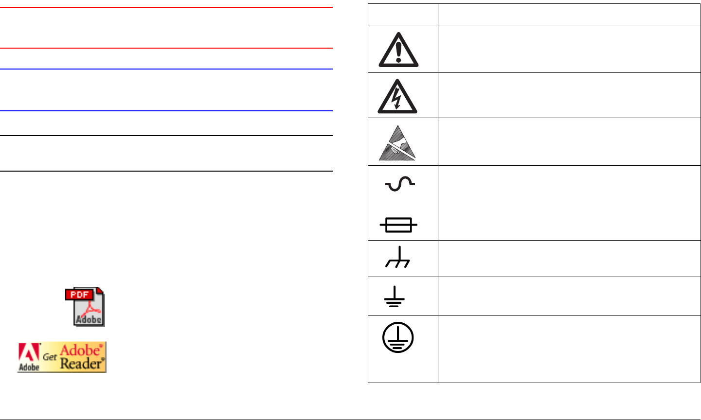
Symbols Used
The following symbols are used on the equipment:
Symbol Meaning
WARNING: General Warning. Risk of Danger
WARNING: Risk of Electric Shock
WARNING: Electrostatic Discharge. Possible
Damage to Equipment
- OR -
Fuse - Identifies fuses or their location.
Frame or Chassis Ground - Identifies the frame or
chassis terminal.
Earth Ground - Identifies the earth Ground Terminal
Protective Earth Ground - Identifies any terminal
which is intended for connection to an external
conductor for protection against electric shock in
case of a fault, or the terminal on a protective earth
electrode.

iiiSTRATA TX Operator’s Guide
Warranty Information
Product Manufactured by MRC:
a. Products manufactured by MRC are warranted against
defects in material and workmanship for a period of two (2) years
from date of delivery as evidenced by MRC's packing slip or
other transportation receipt (unless otherwise noted).
b. MRC's sole responsibility under this warranty will be to either
repair or replace, at its option, any component which fails during
the applicable warranty period because of a defect in material or
workmanship, provided Buyer has promptly reported same to
MRC in writing. All replaced products and parts will become
MRC's property.
c. MRC will honor the warranty at the repair facility designated
by MRC. It is Buyer's responsibility to return, at its expense, the
allegedly defective product to MRC. Buyer must obtain a Return
Material Authorization (RMA) number and shipping instructions
from MRC prior to returning any product under warranty.
Transportation charges for the return of the product to Buyer will
be paid by MRC within the United States. For all other locations,
the warranty excludes all costs of shipping, customs clearance
and other related charges. If MRC determines that the product is
not defective within the terms of this warranty, Buyer will pay
MRC all costs of handling, transportation and repairs at the then
prevailing repair rates.
d. All the above warranties are contingent upon proper use of
the product. These warranties will not apply (1) if adjustment,
repair, or product or parts replacement is required because of
accident, unusual physical, electrical or electromagnetic stress,
neglect, misuse, failure of electric power, environmental controls,
transportation, failure to maintained properly or otherwise in
accordance with MRC specifications, or abuses other than
ordinary use; (2) if the product has been modified by Buyer or
has been repaired or altered outside MRC's repair facility, unless
MRC specifically authorizes such repairs or alterations in each
instance; or (3) where MRC serial numbers, warranty data or
quality assurance decals have been removed or altered.
e. Equipment shipped FOB from Microwave Radio
Communications shall become the property of the buyer upon
delivery and receipt from the carrier. Any damage in shipment
should be handled by the buyer directly with the carrier.
Immediately request the carrier’s inspection upon evidence of
damage during shipment. Do not return any Microwave Radio
Communications product to the factory until a Return Material
Authorization (RMA) number and shipping instructions have
been provided.
f. No person, including any dealer, agent or representative of
MRC is authorized to assume for MRC any other liability on its
behalf except as set forth herein. If any payment is due MRC for
services performed hereunder, it will be subject to the same
payment terms as the original purchase.
Products Manufactured By Others:
For products not manufactured by MRC, the original
manufacturer's or licensor's warranty will be assigned to Buyer to
the extent permitted by the manufacturer or licensor and is in lieu
of any other warranty, expressed or implied. For warranty
information on a specific product, a written request should be
made to MRC.
All Products:
THE FOREGOING WARRANTIES AND REMEDIES ARE
EXCLUSIVE AND ARE IN LIEU OF ALL OTHER EXPRESS OR
IMPLIED WARRANTIES, OBLIGATIONS, AND LIABILITIES ON
THE PART OF MRC. EXCEPT FOR THE EXPRESS

ivSTRATA TX Operator’s Guide
WARRANTIES STATED HEREIN, MRC DISCLAIMS ALL
WARRANTIES ON PRODUCTS FURNISHED HEREUNDER,
INCLUDING, WITHOUT LIMITATION, ALL IMPLIED
WARRANTIES OF MERCHANTABILITY AND FITNESS FOR A
PARTICULAR PURPOSE. MRC WILL HAVE NO
RESPONSIBILITY FOR ANY PARTICULAR APPLICATION
MADE OF ANY EQUIPMENT.
Any description of equipment, whether in writing or made orally
by MRC or its agents, specification sheets, models, bulletins,
drawings, or similar materials used in connection with Buyer's
order are for the sole purpose of identifying the equipment and
will not be construed as an express warranty. Any suggestions
by MRC or its agents regarding use, application or suitability of
the equipment will not be construed as an express warranty. No
warranties may be implied from any course of dealing or usage
of trade. Buyer agrees that the exclusion of all warranties, other
than those expressly provided herein, is reasonable.

Contents
Contents-1STRATA TX Operator’s Guide
About This Manual - - - - - - - - - - - - - - - - - - - - - - - - i
Copyright- - - - - - - - - - - - - - - - - - - - - - - - - - - - - - - i
Proprietary Material - - - - - - - - - - - - - - - - - - - - - - - i
Quality Certification - - - - - - - - - - - - - - - - - - - - - - - i
Regulatory Status- - - - - - - - - - - - - - - - - - - - - - - - - i
Conventions - - - - - - - - - - - - - - - - - - - - - - - - - - - - - - - ii
On-Line Viewing- - - - - - - - - - - - - - - - - - - - - - - - - - ii
Symbols Used- - - - - - - - - - - - - - - - - - - - - - - - - - - - - - ii
Warranty Information - - - - - - - - - - - - - - - - - - - - - - - - - iii
Product Manufactured by MRC: - - - - - - - - - - - - - - - iii
Products Manufactured By Others:- - - - - - - - - - - - - iii
All Products: - - - - - - - - - - - - - - - - - - - - - - - - - - - - iii
Introduction - - - - - - - - - - - - - - - - - - - - - - - - - 1-1
Chapter Overview - - - - - - - - - - - - - - - - - - - - - - - - - 1-1
What This Manual Covers - - - - - - - - - - - - - - - - - - - 1-1
How It’s Organized - - - - - - - - - - - - - - - - - - - - - - - - 1-1
For Whom It’s Written - - - - - - - - - - - - - - - - - - - - - - 1-2
Related Documents - - - - - - - - - - - - - - - - - - - - - - - - 1-2
Ordering Documentation - - - - - - - - - - - - - - - - - - - - 1-2
Calling for Service - - - - - - - - - - - - - - - - - - - - - - - - - 1-2
Supported Repairs - - - - - - - - - - - - - - - - - - - - - - - - 1-3
Tell Us What You Think! - - - - - - - - - - - - - - - - - - - - 1-3
Product Description- - - - - - - - - - - - - - - - - - - 2-1
Chapter Overview - - - - - - - - - - - - - - - - - - - - - - - - - 2-1
System Description - - - - - - - - - - - - - - - - - - - - - - - - 2-1
System Options - - - - - - - - - - - - - - - - - - - - - - - - 2-2
Single Unit Systems - - - - - - - - - - - - - - - - - - - - - 2-3
Multi-Unit Systems - - - - - - - - - - - - - - - - - - - - - - 2-3
Remote Control Options - - - - - - - - - - - - - - - - - - 2-3
Antenna and Power Options - - - - - - - - - - - - - - - 2-3
Mounting and Deployment Options - - - - - - - - - - - 2-5
System Integration - - - - - - - - - - - - - - - - - - - - - - 2-5
System Components - - - - - - - - - - - - - - - - - - - - - - - 2-7
STRATA TXU - - - - - - - - - - - - - - - - - - - - - - - - - - 2-7
STRATA TCU - - - - - - - - - - - - - - - - - - - - - - - - - - 2-7
STRATA ACU - - - - - - - - - - - - - - - - - - - - - - - - - - 2-8
STRATA Remote Control Panels - - - - - - - - - - - - 2-8
TXU and TCU Configurations - - - - - - - - - - - - - - - - - 2-9
Typical System Configurations - - - - - - - - - - - - - - - 2-12
For More Information - - - - - - - - - - - - - - - - - - - - - - 2-12
Routine Operation - - - - - - - - - - - - - - - - - - - - 3-1
Chapter Overview - - - - - - - - - - - - - - - - - - - - - - - - - 3-1
Overview of Controls, Indicators, and Connectors - - - 3-2
TXU Controls, Indicators, and Connectors - - - - - - 3-2
TCU Controls, Indicators, and Connectors - - - - - - 3-5
ACU Controls, Indicators, and Connectors- - - - - - 3-8
STRATA Standard Remote Control Panel Controls,
Indicators, and Connectors- - - - - - - - - - - - - - - - - 3-9
STRATA Aircraft Remote Control Panel Controls,
Indicators, and Connectors- - - - - - - - - - - - - - - - - 3-9
Preparing for Operation - - - - - - - - - - - - - - - - - - - - 3-10
Mobile Installation - - - - - - - - - - - - - - - - - - - - - - 3-10
Portable Deployment - - - - - - - - - - - - - - - - - - - - 3-10
Powering the STRATA TX System - - - - - - - - - - 3-12
Single TCU Power Up and Power Down - - - - - - 3-13
Single TXU Power up and Power Down- - - - - - - 3-14
TXU and TCU Power Up and Power Down -
Co-Located- - - - - - - - - - - - - - - - - - - - - - - - - - - 3-15
TXU and TCU Power Up and Power Down - Separate
Locations - - - - - - - - - - - - - - - - - - - - - - - - - - - - 3-17
Using the STRATA TX Screens - - - - - - - - - - - - - - - 3-19
TXU and/or TCU Monitoring Operations - - - - - - - - - 3-20
Using the Monitor Screens in MPEG Output Mode 3-20

Contents-2STRATA TX Operator’s Guide
Using the Monitor Screens in Ext IF Input Mode 3-22
Using the Monitor Screens in COFDM - IF Mode 3-23
Using the Monitor Screens in COFDM ASI In Mode 3-24
Using the Monitor Screens in Analog - IF Mode- 3-25
Using the Monitor Screens in DVB-S Mode- - - - 3-26
TXU and/or TCU Control Operations - - - - - - - - - - - 3-27
Changing a Preset - - - - - - - - - - - - - - - - - - - - - 3-29
Setting a Channel- - - - - - - - - - - - - - - - - - - - - - 3-30
Setting Power Output - - - - - - - - - - - - - - - - - - - 3-31
Controlling TCU to TXU DC Power on Coax - - - 3-32
Front Panel vs. STRATA TX Configurator Settings - 3-34
Troubleshooting - - - - - - - - - - - - - - - - - - - - - 4-1
Chapter Overview - - - - - - - - - - - - - - - - - - - - - - - - - 4-1
Status LED - - - - - - - - - - - - - - - - - - - - - - - - - - - - - - 4-1
Messages on Display- - - - - - - - - - - - - - - - - - - - - - - 4-1
Error Codes - - - - - - - - - - - - - - - - - - - - - - - - - - - - - 4-3
Primary Error Code- - - - - - - - - - - - - - - - - - - - - - 4-3
Error Status - - - - - - - - - - - - - - - - - - - - - - - - - - 4-8
Unit ID - - - - - - - - - - - - - - - - - - - - - - - - - - - - - - 4-8
Operational Problems - - - - - - - - - - - - - - - - - - - - - - 4-8
Channels & Frequencies - - - - - - - - - - - - - - - A-1
Appendix Overview - - - - - - - - - - - - - - - - - - - - - - - - A-1
Initial Factory Presets - - - - - - - - - - - - - - - - - - - - - - A-1
3.4 to 3.8 GHz Channel Plan - - - - - - - - - - - - - - - A-1
4.4 to 5.0 GHz Channel Plan - - - - - - - - - - - - - - - A-2
6.4 to 7.1 GHz Channel Plan - - - - - - - - - - - - - - - A-2
6.9 to 7.5 GHz Channel Plan - - - - - - - - - - - - - - - A-3
7.4 to 8.0 GHz Channel Plan - - - - - - - - - - - - - - - A-3
7.8 to 8.5 GHz Channel Plan - - - - - - - - - - - - - - - A-4
8.2 to 8.9 GHz Channel Plan - - - - - - - - - - - - - - - A-4
10.0 to 10.7 GHz Channel Plan - - - - - - - - - - - - - A-5
10.5 to 11.2 GHz Channel Plan - - - - - - - - - - - - - A-5
10.8 to 11.5 GHz Channel Plan - - - - - - - - - - - - - A-6
12.7 to 13.25 GHz Channel Plan- - - - - - - - - - - - - A-6
Glossary - - - - - - - - - - - - - - - - - - - - - - - - - - - B-1

1
Introduction 1-1STRATA TX Operator’s Guide
Introduction
1.1 Chapter Overview
This chapter will introduce you to the Operator’s Guide: what it
covers, how it’s organized, and for whom it’s written.
1.2 How to Use This Manual
This manual was prepared to be viewed on a Windows-based
PC. A pdf file for this manual is provided on the CD ROM
delivered with each STRATA Transmitter (TX) System. The CD
ROM contains pdf files for the Operator’s Guide, the Technical
Reference Manual, and the Quick Reference Cards. Hardcopies
of the Operator’s Guide, the Technical Reference Manual, and
the Quick Reference Cards are also delivered with each
STRATA TX System.
Viewing of this manual on-line requires Adobe Acrobat, Version
4.0 or above. Click on the following icon to download your FREE
copy of Adobe Acrobat Reader.
When viewing this manual on-line, text displayed as blue
contains a hypertext link. Click on the blue hypertext link to
jump to that destination. If the destination link is also blue, click
on the blue destination link to return.
1.3 What This Manual Covers
This manual describes how to operate the STRATA TX
Transmitter System.
For information on Installation, Repair, Replacement Parts, and
Theory of Operation, refer to the STRATA TX Technical
Reference Manual.
This manual also covers various configurations of the STRATA
TX System. Your STRATA TX System will consist of one of the
following configurations:
• A Standalone Transmitter Control Unit (TCU)
• A Standalone Transmitter Unit (TXU)
• A TCU and TXU.
Your TX System may be mounted on a tripod or may be mounted
in a vehicle or in an aircraft. Your TX System may also include an
optional MRC AC to DC Converter Unit (ACU).
If your system is mounted in a vehicle or in an aircraft, it may
include an optional MRC Remote Control Panel or Aircraft
Remote Control Panel. This manual provides coverage for all of
these various configurations.
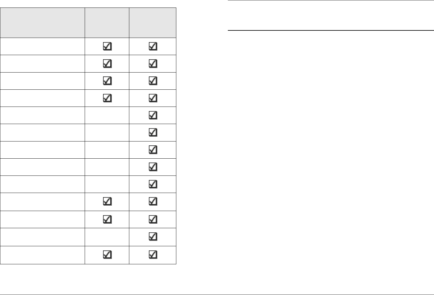
1.4 How It’s Organized
The manuals for the STRATA TX System are organized as
follows:
Introduction 1-2STRATA TX Operator’s Guide
Chapter Operator’s
Guide
Technical
Reference
Manual
Introduction
Product Description
Routine Operation
Troubleshooting
Advanced Operation
Installation
Repair
Replacement Parts
Theory of Operation
Appendix A - Channels
& Frequencies
Appendix B - Glossary
Appendix C -
Configurator Reference
Appendix D -
Specifications
Note The Technical Reference Manual contains
everything in the Operator’s Guide, plus additional
technical content.
1.5 For Whom It’s Written
This manual is intended for use by personnel assigned to
operate the STRATA TX System. Users of this manual should
already be familiar with basic concepts of radio, video, and
audio.
1.6 Related Documents
• STRATA TX System Technical Reference Manual
(part no. 400505-1)
• STRATA TX System Quick Reference Card
(part no. 400506-1)
• STRATA Aircraft Remote Control Panel Operator’s Guide
(part no. 400490)
• STRATA Remote Control Panel Operator’s Guide
(part no. 400489)
1.7 Ordering Documentation
Any of the above manuals may be ordered by contacting MRC
Customer Service:
Business Hours: Monday - Thursday
8:00 AM - 7:00 PM Eastern Time (US)
(0800 - 1900 hrs US ET)

Introduction 1-3STRATA TX Operator’s Guide
Friday
8:00 AM - 5:00 PM Eastern Time (US)
(0800 - 1700 hrs US ET)
Telephone: 800-490-5700 (Press 3)
978-671-5700 (Press 3)
Fax: 978-671-5800
E-mail customerservice@mrcbroadcast.com
When contacting Customer Service, please have the following
information available:
• Model number and serial number of the unit. This is
located on a label on the bottom of each unit.
• Approximate purchase date.
• Radio version, which appears on the TXU or TCU
alphanumeric display at startup.
or
• Firmware versions displayed on the Main page of the
STRATA TX Configuration Utility, when the STRATA TX
Configuration Utility is connected to the TXU or TCU.
1.8 Calling for Service
MRC Technical Support is available 24 hours a day, 7 days a
week. During regular business hours you can reach our expert
staff directly.
Business Hours: Monday - Friday
8:00 AM - 7:00PM Eastern Time (US)
(0800 - 1900 hrs US ET)
Telephone: 800-490-5700 (Press 4)
978-671-5700 (Press 4)
Fax: 978-671-5800
E-mail: technicalsupport@mrcbroadcast.com
After regular business hours and on weekends and holidays, you
can also reach our expert staff as follows:
Telephone: 978-671-5929
Your call will be automatically forwarded to the on-call Technical
Support specialist.
When contacting Technical Support, please have the following
information available:
• Model number and serial number of the unit. This is
located on a label on the bottom of each unit.
• Approximate purchase date.
• Radio version, which appears on the TXU or TCU
alphanumeric display at startup.
or
• Firmware versions displayed on the Main page of the
STRATA TX Configuration Utility, when the STRATA TX
Configuration Utility is connected to the TXU or TCU.
1.9 Supported Repairs
The STRATA TX System, including the TXU, TCU, and optional
ACU, is designed to be compact, rugged and reliable.

Introduction 1-4STRATA TX Operator’s Guide
The TXU and TCU require specialized test equipment to
calibrate amplitude and frequency characteristics after repair. In
addition, sealing the TXU, TCU, or optional ACU enclosures
after repair requires exacting techniques and special fixtures to
ensure weather resistance of the units.
Therefore, there are NO supported field repairs to either the
TXU, TCU, or ACU.
Return the entire unit for factory repair.
If you attempt field repair, you risk damaging your
equipment. If your equipment is under warranty, you may also
affect your warranty coverage.
1.10 Tell Us What You Think!
We’d appreciate any comments or suggestions you have about
this manual. The more feedback we get, the better the manuals
get!
If you’re viewing this manual electronically, it’s easy - just click on
the link below send us an E-mail.
Or, you can E-mail our Technical Support team at:
technicalsupport@mrcbroadcast.com
Be sure to tell us what product you’re writing about, and which
manual - the Operator’s Guide, the Quick Reference Card, or the
Technical Reference Manual.
Feedback

2
Product Description 2-1STRATA TX Operator’s Guide/Tech Ref Manual
Product Description
2.1 Chapter Overview
This chapter provides an overall description of the STRATA TX
System, its components, and its capabilities.
Here are the topics covered:
Topic Page
System Description 2-1
System Options 2-2
Single Unit Systems 2-3
Multi-Unit Systems 2-3
Remote Control Options 2-3
Antenna and Power Options 2-3
Mounting and Deployment Options 2-5
System Integration 2-5
System Components 2-7
STRATA TXU 2-7
STRATA TCU 2-7
STRATA ACU 2-8
STRATA Remote Control Panels 2-8
TXU and TCU Configurations 2-9
Typical System Configurations 2-12
For More Information 2-12
2.2 System Description
The STRATA TX System is a highly reliable, flexible, and
compact portable microwave transmitter system ideal for tripod,
airborne, or mobile installations. A typical STRATA TX System is
composed of the Transmitter Unit (TXU) and the Transmitter
Control Unit (TCU), as shown in Figure 2-1 on page 2-2. This
modular architecture allows you the maximum flexibility in
configuration, siting, and operation.
The STRATA TX System key features are:
• Analog, Digital, or Analog/Digital Switchable
• MPEG Encoding (4:2:0, 4:2:2)
• COFDM Modulation with Forward Error Correction and
Selectable Guard Band Interval
• Digital Modulation for QPSK, 16 QAM, and 64 QAM
• NTSC or PAL Modulation with Audio (4 mono or 2 stereo)
• Tripod, Half Rack, or Full Rack Mounts
• Front Panel Local Control
• Remote Control
• Bands from 3.4 to 13.25 GHz
Product Description 2-2STRATA TX Operator’s Guide/Tech Ref Manual Product Description 2-2STRATA TX Operator’s Guide/Tech Ref Manual
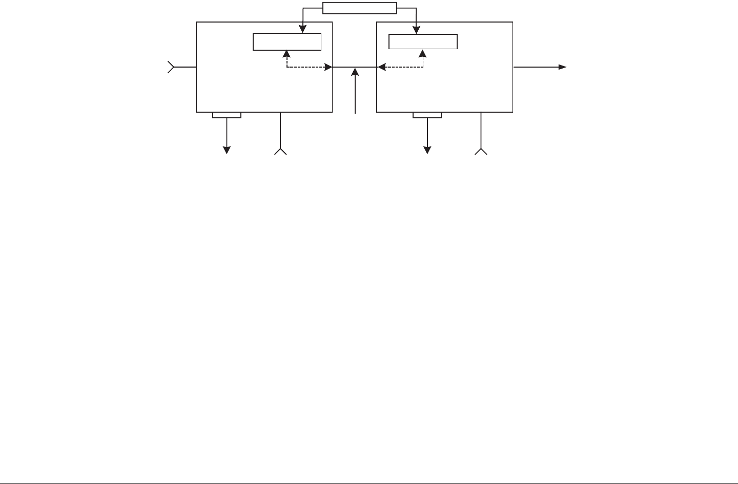
Figure 2-1: STRATA TX System Block Diagram
TCU TXU
yNTSC
yPAL
ySDI
yASI
yIF
RF Out
Telemetry Telemetry
DC Power and/or IF
IN
+28 VDC
RS-232
1.84 MHz OOK Tone
+28 VDC
RS-232
The STRATA TX System TXU and the TCU may be operated in
stand-alone configurations depending upon specific video
applications.
2.2.1 System Options
The STRATA TX System can be ordered configured for 1 of 11
specific RF bands as follows:
• 3.4 to 3.9 GHz
• 4.4 to 5.0 GHz
• 6.4 to 7.1 GHz
• 6.9 to 7.5 GHz
• 7.4 to 8.1 GHz
• 7.8 to 8.5 GHz
• 8.2 to 8.9 GHz
• 10.0 to 10.7 GHz
• 10.5 to 11.2 GHz
• 10.8 to 11.5 GHz
• 12.7 to 13.25 GHz
MRC is constantly working to expand and upgrade the
capabilities of the STRATA TX System. Consult your Sales
Representative or contact the factory for the latest band
availability.
The STRATA TX System (typically) consists of the following
components:
TXU The Transmitter Unit (TXU) can be equipped with either an
FM Modulator or COFDM/MPEG module, but not both. A High
Power Unit (HPU) is also contained within the TXU housing to
increase RF power output.

Product Description 2-3STRATA TX Operator’s Guide/Tech Ref Manual
TCU The Transmitter Control Unit (TCU) can be equipped with
either an FM Modulator or COFDM/MPEG module, or both.
ACU The optional AC to DC Power Converter (ACU) provides
+28 VDC power from an AC power source to power one or more
units in a system.
Remote Control Panels Optional Remote Control Panels are
available to allow remote control of the STRATA TX System from
an instrument panel during airborne or mobile operations.
2.2.2 Single Unit Systems
The TXU or TCU may be used independently in single-unit
applications as follows:
• The TXU may be used as a stand-alone transmitter
accepting an IF input.
• The TXU may be used as a stand-alone transmitter
featuring FMT modulation or MPEG and COFDM.
• The TCU may be used as a stand-alone unit used for
FMT modulation or MPEG and COFDM, or both FMT
modulation and MPEG and COFDM.
2.2.3 Multi-Unit Systems
The TXU and TCU can be configured as part of an integrated
system as follows:
• The TCU may contain the FMT modulator and MPEG/
COFDM module supplying an IF signal to a TXU
containing only the RF transmitter.
• The TXU may contain the RF modulator or MPEG/
COFDM module supplying an RF signal directly to the
transmitter antenna.
• The TCU can be separated from the TXU in applications
where the transmitter needs to be placed in another
location.
2.2.4 Remote Control Options
For portable mobile or airborne operations, the STRATA TX
System may be controlled by one of two models of Remote
Control Panels. The Remote Control Panels are mounted in
mobile racks or aircraft instrument panels and are connected via
an RS-232 cable between the Remote Control Panel and the
STRATA TX System.
2.2.5 Antenna and Power Options
The flexible architecture of the STRATA TX System allows a
number of options for both the transmit antenna and the power.
Antenna Options The STRATA TX System is fully compatible
with the MRC family of transmit antennas, including:
• OmniPole omnidirectional
• Megahorn compact horn
• SectorScan flat panel
• MicroScan parabolic
• Ellipse parabolic
Contact your Sales Representative to explore the wide array of
antenna choices available.
CAUTION To prevent damage to your STRATA TX
System, MRC recommends using a +28
VDC power supply. Do not exceed +36
VDC input power or damage will occur.
Product Description 2-4STRATA TX Operator’s Guide/Tech Ref Manual
Power Options The STRATA TX System configurations
operate on +28 VDC power, supplied externally. This DC power
can be supplied by the optional STRATA ACU, or from another
DC power source. Contact your Sales Representative for the
latest details.
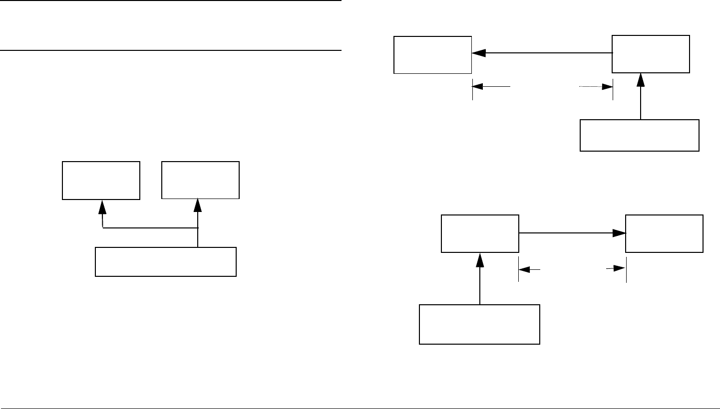
Note A TCU and TXU are defined as being “co-located”
when the TXU and TCU are physically separated
by not greater than 6 feet.
If the TXU and TCU are co-located, power must be supplied to
each unit through their individual power connectors from the
same power source. See Figure 2-2. Do not use DC on coax to
power the TXU or TCU when the units are co-located.
Figure 2-2: Powering the TXU and TCU Independently
If your installation calls for separating the TXU and TCU, the
TXU is powered by DC supplied by the TCU or the TCU is
powered by DC supplied by the TXU. The DC power is
superimposed on the coaxial cable connected between the units.
See Figure 2-3 and Figure 2-4.
The DC input voltage to the unit co-located with the DC power
supply must be greater than +24 VDC.
STRATA
TCU
DC Power (+28 V)
STRATA
TXU
Branched
Power Cable
Refer to the “Installation” Chapter on page 6-1 (part of the
STRATA TX Technical Reference Manual only) for additional
information.
For those applications that use a TCU in a standalone mode, i.e.,
to generate ASI or DVB-S signals, DC power from the TCU to
the TXU or from the TXU to the TCU cannot be used.
Figure 2-3: Powering the TXU from the TCU
Figure 2-4: Powering the TCU from the TXU
STRATA
TXU
STRATA
TCU
DC Power (+28 V)
Up to 600 ft.
(180 m)
Coax
Power
Cable
STRATA
TCU
STRATA
TXU
DC Power (+28 V )
Coax
Up to 600 ft.
(180 m)

Product Description 2-5STRATA TX Operator’s Guide/Tech Ref Manual
DC power superimposed on the coaxial cable between a TCU
and a TXU can be supplied from either the TCU or TXU,
depending upon the location of the DC power supply. Coaxial
cable length/voltage limitations exist when powering from either
the TXU or TCU. These limitations are based on cable size, DC
voltage input, cable resistance, and cable length. A maximum
length of 600 feet (180 meters) between the TXU and TCU is
supported. Contact MRC Technical Support for more information
on cable requirements.
DC power required for a STRATA TX System depends upon the
TX System configuration, i.e., if the TXU or TCU are operated in
a standalone mode, if the TXU and TCU are co-located, or if the
TXU and TCU are mounted in separate locations. See Figure 2-
5 on page 2-6 for the various STRATA TX System configurations
available.
For TX Systems that use DC power sources other than a
STRATA ACU, contact MRC Technical Support for additional
power information.
2.2.6 Mounting and Deployment Options
The STRATA TX offers a number of options for either mobile or
portable applications.
For more details on installation of the STRATA TX in various
applications, see the “Installation” Chapter on page 6-1 (part of
the STRATA TX Technical Reference Manual only).
Mobile Installation For mobile applications such as in a vehicle
or in an aircraft, the STRATA TX System is usually mounted in an
MRC fixed mounting bracket and is installed in a bulkhead or
compartment. The cabling is permanently installed and power
comes from aircraft or vehicle power.
Portable Deployment In portable applications, the STRATA TX
System will be moved from place to place and set up each time.
The TXU and TCU will usually be mounted in a MRC universal
mounting bracket. The bracket is attached to a tripod using a
mounting plate and quick release.
The cabling between the TXU and TCU is typically left in place
and the power, antenna, and audio/video connections are
removed at the end of each deployment.
2.2.7 System Integration
System Communication When the TXU and TCU are
connected, they automatically communicate via signals
superimposed on the coaxial cable between the two units. This
allows them to share information on installed hardware, preset
configurations, current status, and alarms.
System Operation Once the TXU and TCU are connected and
communicating, the units work seamlessly together. System
settings can be selected and modified from the front panel of
either unit, regardless of which unit holds the hardware being
configured.
System Configuration The STRATA TX System offers two
levels of system configuration, designed to match the needs of
different personnel.
For the field operator, the STRATA TX System has up to 9
Presets that can be selected from the front panel. Each Preset
controls key parameters such as modulation, frequency, and
audio and video settings. Additional settings that are front panel-
controlled include band, channel, offset, and filtering.
For the advanced operator and technical staff, the STRATA TX
Configurator software allows complete control of all parameters
in the STRATA TX System. The STRATA TX Configurator
software runs on a Windows-based PC and connects to either
the TXU or the TCU via an RS-232 serial interface cable.
Product Description 2-6STRATA TX Operator’s Guide/Tech Ref Manual
Interfacing a PC to either the TXU or TCU in a connected system
gives you complete control of both units. You can read the
current settings, program new settings, or return the units to their
factory default settings. The STRATA TX Configurator software
automatically detects what hardware is installed in the system
and assigns the appropriate configuration to the correct
hardware, regardless of which unit holds the hardware being
configured.
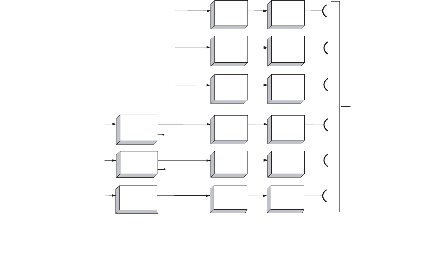
Figure 2-5: STRATA TX System Options
TXU
TXU
TXU
TXU
TXU
TCU
TCU
RXU
70 MHz IF Output Only
NTSC or PAL Analog Video
with 4 Audio Channels Available
SDI, ASI, NTSC or PAL
& Digitial/Analog Audio
1.9 to 2.5 GHz
or 2.3 to 2.7 GHz
RF Output
SDI, ASI, NTSC or PAL
& Digitial/Analog Audio
Digital Video + Audio
Analog Video + Audio
ASI Monitor
ASI Monitor
RF/IF Only
RF/IF Only
RF/IF Only
COFDM / MPEG
COFDM / MPEG
& FMT
FMT Option
COFDM / MPEG
Option
TXU
TCU
RF/IF Only
HPU
HPU
HPU
HPU
HPU
RXU
(OPTIONAL)
(OPTIONAL)
(OPTIONAL)
(OPTIONAL)
(OPTIONAL)
HPU
(OPTIONAL)
FMT Only
Product Description 2-7STRATA TX Operator’s Guide/Tech Ref Manual
2.3 System Components
This section will provide more details about each the
components of a STRATA TX System:
•STRATA TXU
• STRATA TCU
•STRATA ACU
• STRATA Remote Control Panels
For details on connections between the STRATA TX System
components, refer to the “Installation” chapter (part of the
STRATA TX Technical Reference Manual only).
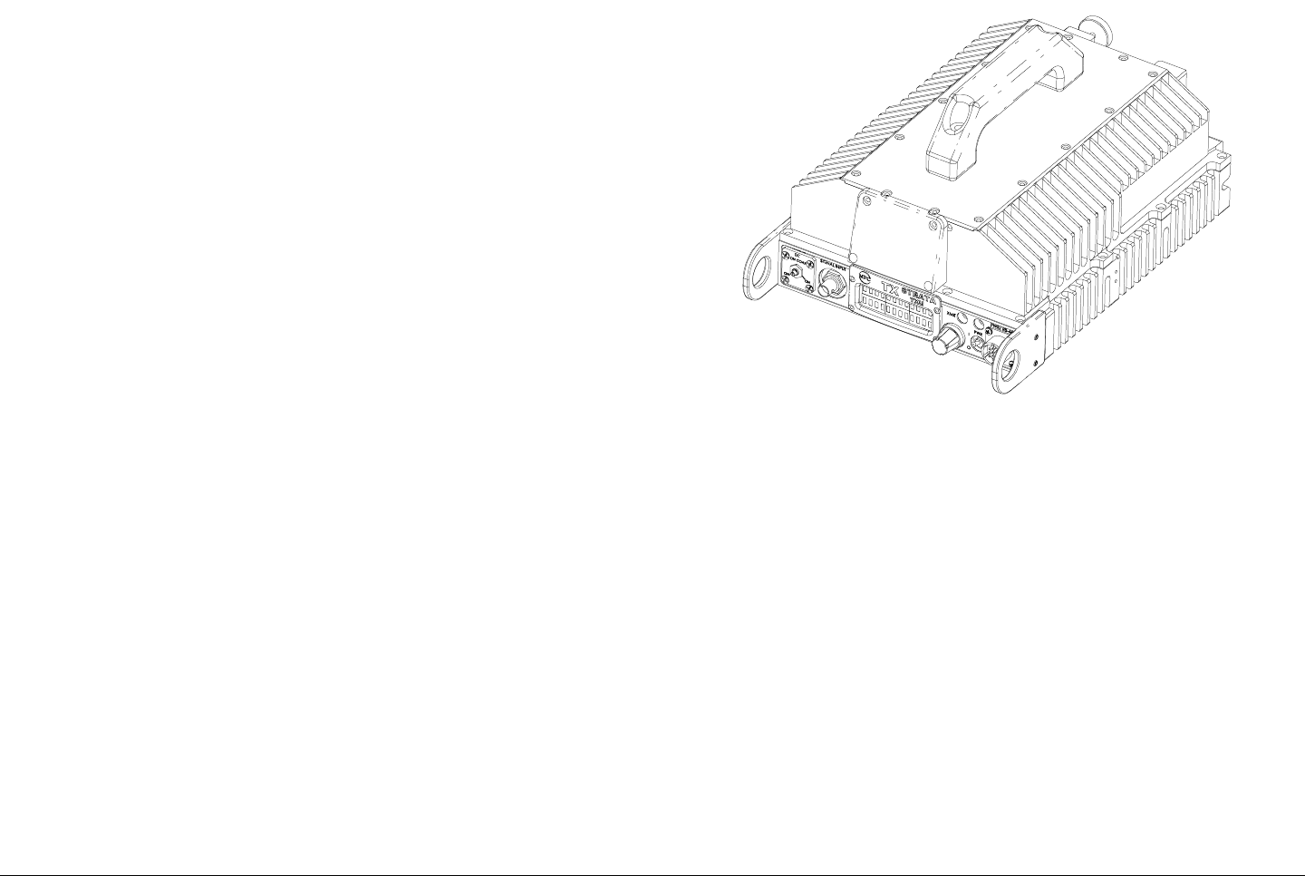
2.3.1 STRATA TXU
The TXU (See Figure 2-6) always contains an IF/RF module that
accepts either a 70 MHz COFDM, FMT IF, or external 70 MHz
input signal and up-converts these signals to the required RF
band. The RF frequency synthesizer circuit included in the IF/RF
unit, in conjunction with the command and control power supply
module, provides the means to channelize RF video and audio
signals in the TX System RF band.
The TXU, with either an analog (FMT) or digital (MPEG/COFDM)
module, is integrated in the same housing as the HPU
components. This provides the ability to incorporate high RF
power output (12 watts of saturated RF power) into a single
analog or digital transmitter assembly.
Standard U.S. FCC band plans, as well as customer-created
channel plans, may be customized using the STRATA TX
Configurator software.
Figure 2-6: STRATA TXU
As noted previously, the TXU may also include either an MPEG/
CODFM or FMT module (but not both), in which case the TXU
serves as a stand-alone digital or analog video microwave
transmission system.
2.3.2 STRATA TCU
The TCU (See Figure 2-7 on page 2-8) may contain either
analog or digital or both analog and digital video modulation
modules. Where an application might initially employ only
analog video transmission but expects to migrate to dual,
switchable, analog and digital operation, the TCU may be
upgraded to add the MPEG/COFDM module to add this
capability.
Product Description 2-8STRATA TX Operator’s Guide/Tech Ref Manual
Figure 2-7: STRATA TCU
Where only digital or analog video transmission is desired, the
MPEG/COFDM or FMT modules may be installed in a TXU,
thereby eliminating the need for a TCU. The STRATA TX design
does not permit splitting digital and analog video modulator
modules between a TXU and a TCU.
A TCU may also consist of a stand-alone configuration whereby
either or both MPEG/COFDM and FMT modules may be used
independent of the TXU. This configuration permits use of a TCU
equipped with analog and/or digital video modulation modules
for a variety of signal input and output configurations, including a
digital option using NTSC or PAL composite video input and ASI
(digital) signal output.
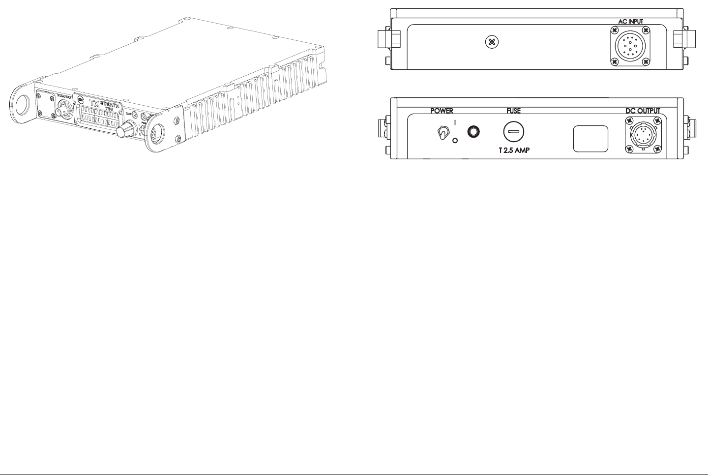
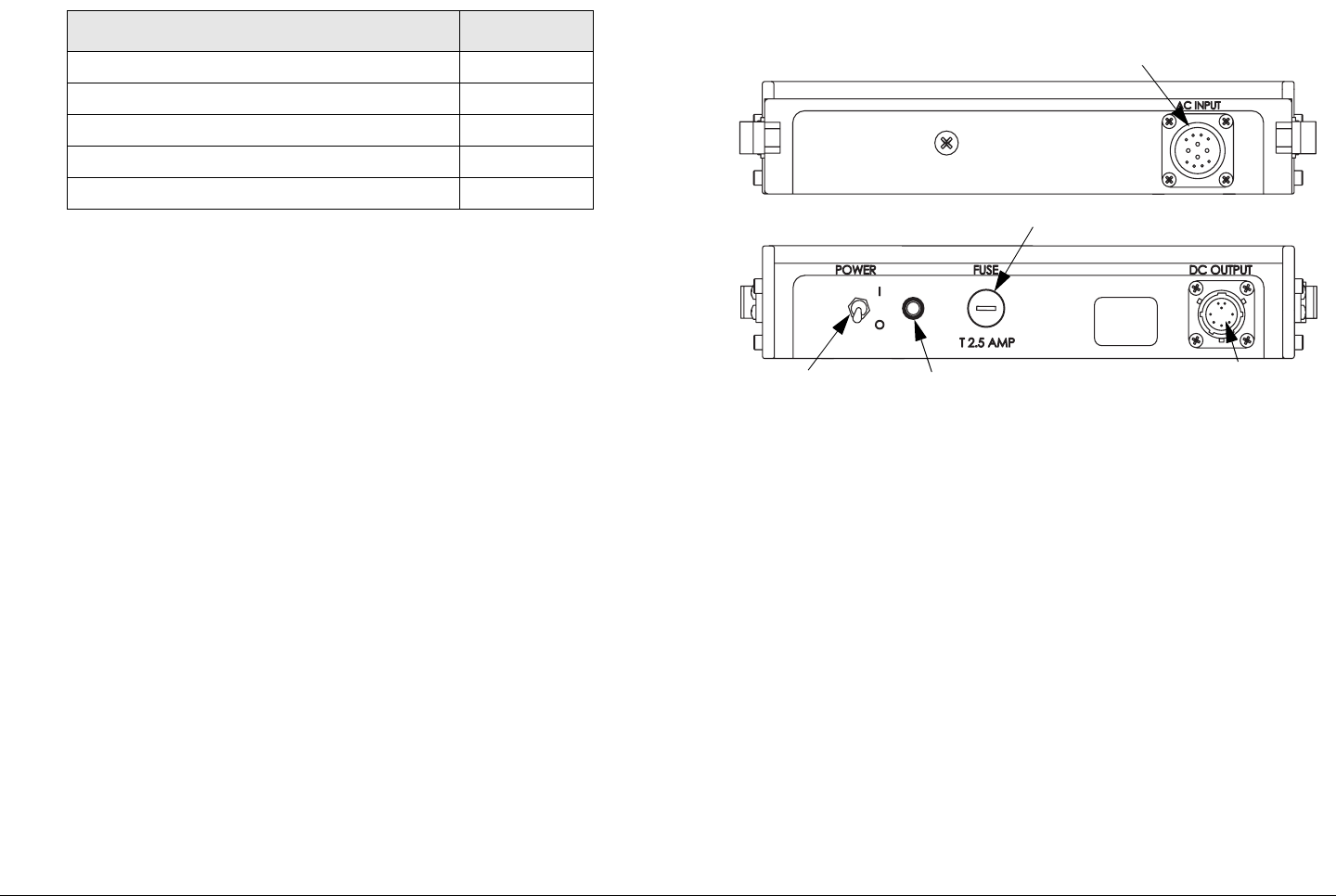
2.3.3 STRATA ACU
For fixed or portable deployment applications, the STRATA TX
System may be powered by the optional AC to DC Converter
(ACU). See Figure 2-8.
Figure 2-8: AC to DC Converter
The ACU installs as part of an integrated stack for either tripod or
fixed applications. The ACU may also be used to power the TXU
or TCU only when a TXU and TCU are not co-located. In this
case, the TXU would receive DC power from the TCU or the
TCU would receive DC power from the TXU superimposed on
the coaxial cable connected between the units.
In standalone TXU or TCU operations, the optional ACU may be
used to supply DC power directly to the applicable unit. In the
case where a TXU and a TCU are co-located, it is recommended
that both the TXU and TCU be powered directly from the ACU in
lieu of supplying DC power from the TCU to the TXU or from the
TXU to the TCU via the coaxial cable connected between the
units.
2.3.4 STRATA Remote Control Panels
For mobile or airborne operations, two Remote Control Panel
models are currently available. Contact your Sales
Representative for the latest information.
OUTPUT
OUTPUT
< >
< >
DC
DC
Product Description 2-9STRATA TX Operator’s Guide/Tech Ref Manual
Both Remote Control Panel models provide simplified transmit
operations by allowing the operator or pilot to select either
analog or digital pre-configured Presets, Channels, and Offsets,
depending upon the required operating mode.
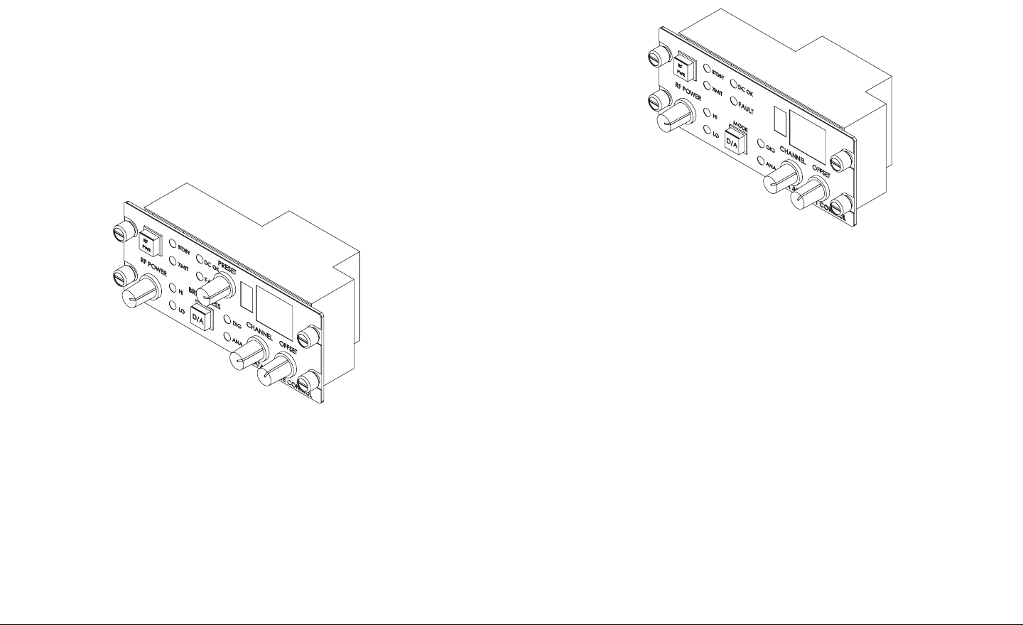
Standard Remote Control Panel The standard STRATA
Remote Control Panel (See Figure 2-9) provides instrument
panel remote control of the STRATA TX System for mobile
operations and features 9 selectable Presets.
For additional information, refer to the STRATA Remote Control
Panel Operator’s Guide (part no. 400489).
Figure 2-9: Standard Remote Control Panel
Aircraft Remote Control Panel The STRATA Aircraft Remote
Control Panel (See Figure 2-10) is a simplified version of the
standard STRATA Remote Control Panel. This panel provides
instrument panel remote control of the STRATA TX System for
airborne operations. This model features only two Presets for
ease of operation.
The unit is designed to fit a standard aircraft instrument panel
and provides user-friendly controls, combined with well placed
and easy to read LED displays and color indicators.
For additional information, refer to the STRATA Aircraft Remote
Control Panel Operator’s Guide (part no. 400490).
Figure 2-10: Aircraft Remote Control Panel
2.4 TXU and TCU Configurations
TXU Different configurations of the TXU are available,
depending upon if your TX System contains a standalone TXU or
if your TX System contains both a TXU and TCU. The different
configurations are described below.
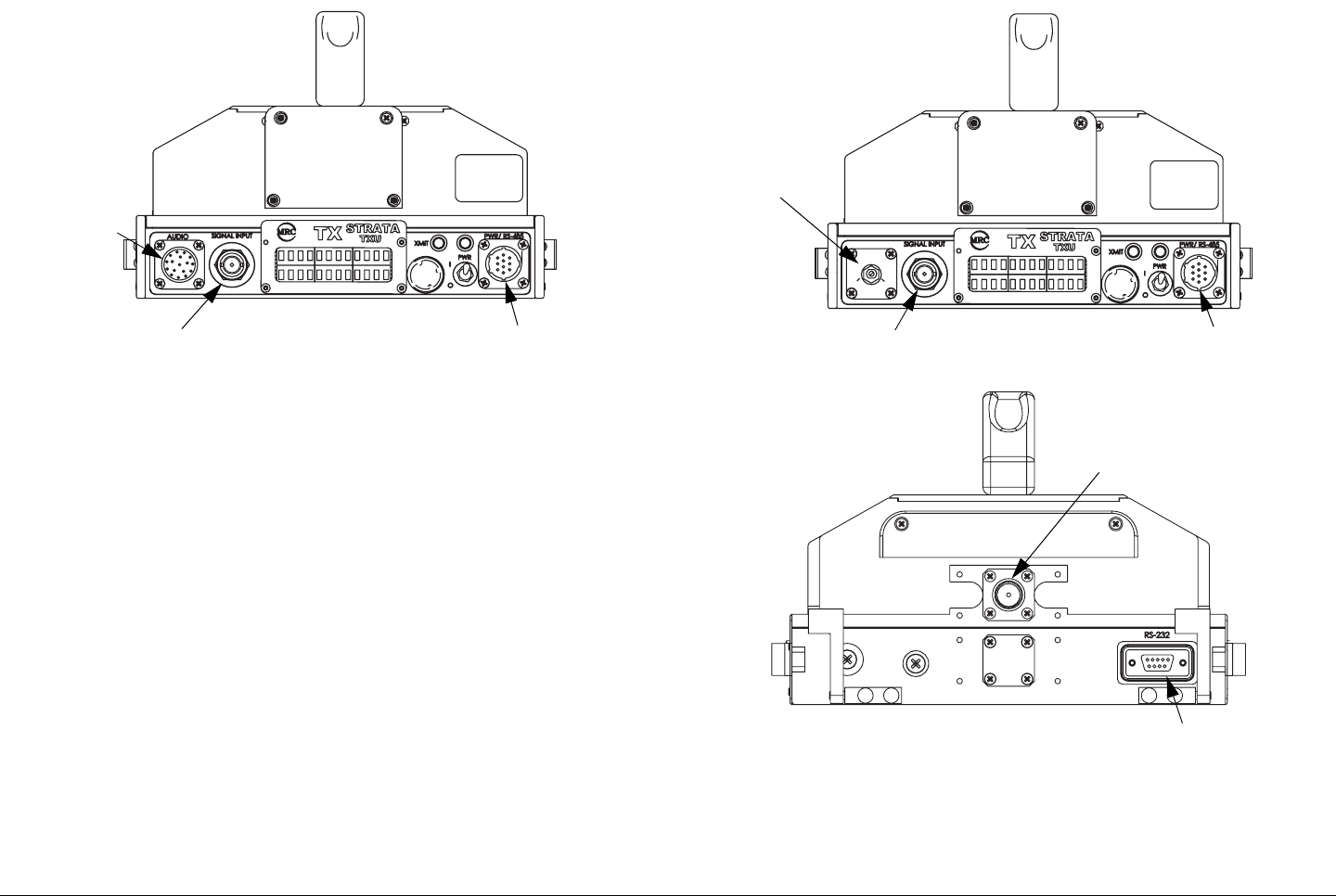
If your TXU is equipped with either an analog (FMT) module or a
digital (MPEG/COFDM) module and was ordered to operate in a
standalone mode without a TCU, the front panel will contain an
AUDIO connector. See Figure 2-11 on page 2-10.
Product Description 2-10STRATA TX Operator’s Guide/Tech Ref Manual
Figure 2-11: Standalone TXU Configuration
If your TXU was ordered to operate with a TCU, it will not contain
either analog or digital modules and will therefore not contain an
AUDIO connector. The AUDIO connector is replaced by a DC
ON COAX switch. See Figure 2-12.
The DC ON COAX switch allows manual control of DC power to
the TXU from the TCU or from the TCU to the TXU via DC power
superimposed on the coaxial cable connected between the two
units.
The rear of the TXU is identical on both configurations of the
TXU. See Figure 2-12.
DO NOT
EXCEED
36 VOLTS DC
Front View
AUDIO
Connector
SIGNAL INPUT
Connector
PWR/RS-485
Connector
Figure 2-12: TXU - TXU with TCU Configuration
DO NOT
EXCEED
36 VOLTS DC
DC
ON COAX
OFF ON
Rear View
Front View
DC ON COAX
Switch
SIGNAL INPUT
Connector
PWR/RS-485
Connector
RS-232
Connector
RF Output
Connector
Product Description 2-11STRATA TX Operator’s Guide/Tech Ref Manual
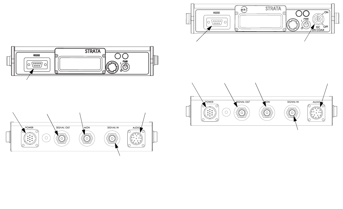
TCU Several different configurations of the TCU also exist as
the result of technical updates. Configuration differences are
described below.
TCU - Older Configuration If your TCU is an older
configuration, the controls and connectors contained on the TCU
are similar to those shown in Figure 2-13. Older configurations
do not contain the front panel DC ON COAX override switch to
provide manual control of DC power to a TXU.
Figure 2-13: TCU - Older Configuration
TCU - Newer Configuration If your TCU is the newer
configuration, the controls and connectors contained on the TCU
are similar to those shown in Figure 2-14. A DC ON COAX
TCU
TX
XMIT
Front View
Rear View
RS-232
Connector
POWER
Connector
AUDIO
Connector
Monitor (MON)
Connector
SIGNAL IN
Connector
SIGNAL OUT
Connector
switch is located on the front panel to provide manual control of
DC power to a TXU.
Figure 2-14: TCU - Newer Configuration
TCU
TX
XMIT
Rear View
Front View DC ON COAX
Switch
SIGNAL IN
Connector
AUDIO
Connector
Monitor (MON)
Connector
SIGNAL OUT
Connector
POWER
Connector
RS-232
Connector
Product Description 2-12STRATA TX Operator’s Guide/Tech Ref Manual
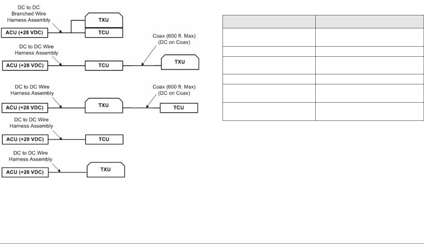
2.5 Typical System Configurations
Typical STRATA TX System configurations are shown in Figure
2-15.
Figure 2-15: STRATA TX System Configurations
2.6 For More Information
Additional detailed technical information about the STRATA TX
System is contained in the STRATA TX Technical Reference
Manual. Specific topics contained in the Technical Reference
Manual are listed below:
Topic Chapter
Changing settings using
the Configurator software
See Chapter 5, “Advanced
Operation”
Installation See Chapter 6, “Installation”
Connections to other
equipment
See Chapter 6, “Installation”
Supported Repairs See Chapter 7, “Repair”
Repair Parts See Chapter 8, “Replacement
Parts”
Block Diagram See Chapter 9, “Theory of
Operation”
3
Routine Operation 3-1STRATA TX Operator’s Guide/Tech Ref Manual
Routine Operation
3.1 Chapter Overview
This chapter provides basic information that will enable you to
operate your STRATA TX System.
Here are the topics covered:
Topic Page
Overview of Controls, Indicators, and
Connectors
3-2
TXU Controls, Indicators, and
Connectors
3-2
TCU Controls, Indicators, and
Connectors
3-5
ACU Controls, Indicators, and
Connectors
3-8
STRATA Standard Remote Control
Panel Controls, Indicators, and
Connectors
3-9
STRATA Aircraft Remote Control Panel
Controls, Indicators, and Connectors
3-9
Preparing for Operation 3-10
Mobile Installation 3-10
Portable Deployment 3-10
Powering the STRATA TX System 3-12
Single TCU Power Up and Power Down 3-13
Single TXU Power up and Power Down 3-14
TXU and TCU Power Up and Power
Down - Co-Located
3-15
TXU and TCU Power Up and Power
Down - Separate Locations
3-17
Information on settings made with the STRATA TX Configuration
Utility software can be found in the “Advanced Operation”
Chapter on page 5-1 (part of the STRATA TX System Technical
Reference Manual only).
For a summary of settings that can be made with the TXU and
TCU front panel control switches and which settings are made
using the STRATA TX Configuration Utility, see Section 3.7 on
page 3-35.
Using the STRATA TX Screens 3-20
TXU and/or TCU Monitoring Operations 3-20
Using the Monitor Screens in MPEG
Output Mode
3-21
Using the Monitor Screens in Ext IF
Input Mode
3-23
Using the Monitor Screens in COFDM -
IF Mode
3-24
Using the Monitor Screens in COFDM
ASI In Mode
3-25
Using the Monitor Screens in Analog -
IF Mode
3-26
Using the Monitor Screens in DVB-S
Mode
3-27
TXU and/or TCU Control Operations 3-28
Changing a Preset 3-30
Setting a Channel 3-31
Setting Power Output 3-32
Controlling TCU to TXU DC Power on
Coax
3-33
Front Panel vs. STRATA TX Configurator
Settings
3-35
Routine Operation 3-2STRATA TX Operator’s Guide/Tech Ref Manual
3.2 Overview of Controls, Indicators,
and Connectors
This section describes the controls, indicators, and connectors
used on the STRATA TX System.
3.2.1 TXU Controls, Indicators, and Connectors
Controls, indicators, and connectors contained on the TXU are
identified and described below. Topics covered are as follows:
Each of these controls, indicators, and connectors are described
in more detail in the following paragraphs.
Controls, indicators, and connectors contained on the TXU front
panel are shown in Figure 3-1. Connectors contained on the
TXU rear panel are shown in Figure 3-2 on page 3-3. For
configuration differences in the TXU, see “TXU and TCU
Configurations” on page 2-9.
Topic Page
TXU Front Panel DC ON COAX
Switch
3-2
TXU SIGNAL INPUT Connector 3-3
TXU AUDIO Connector 3-3
TXU Alphanumeric Display 3-3
TXU XMIT LED 3-3
TXU Status LED 3-4
TXU PWR/RS-485 Connector 3-4
TXU PWR Switch 3-4
TXU Control Switch 3-4
TXU RF Output Connector 3-5
TXU RS-232 Connector 3-5
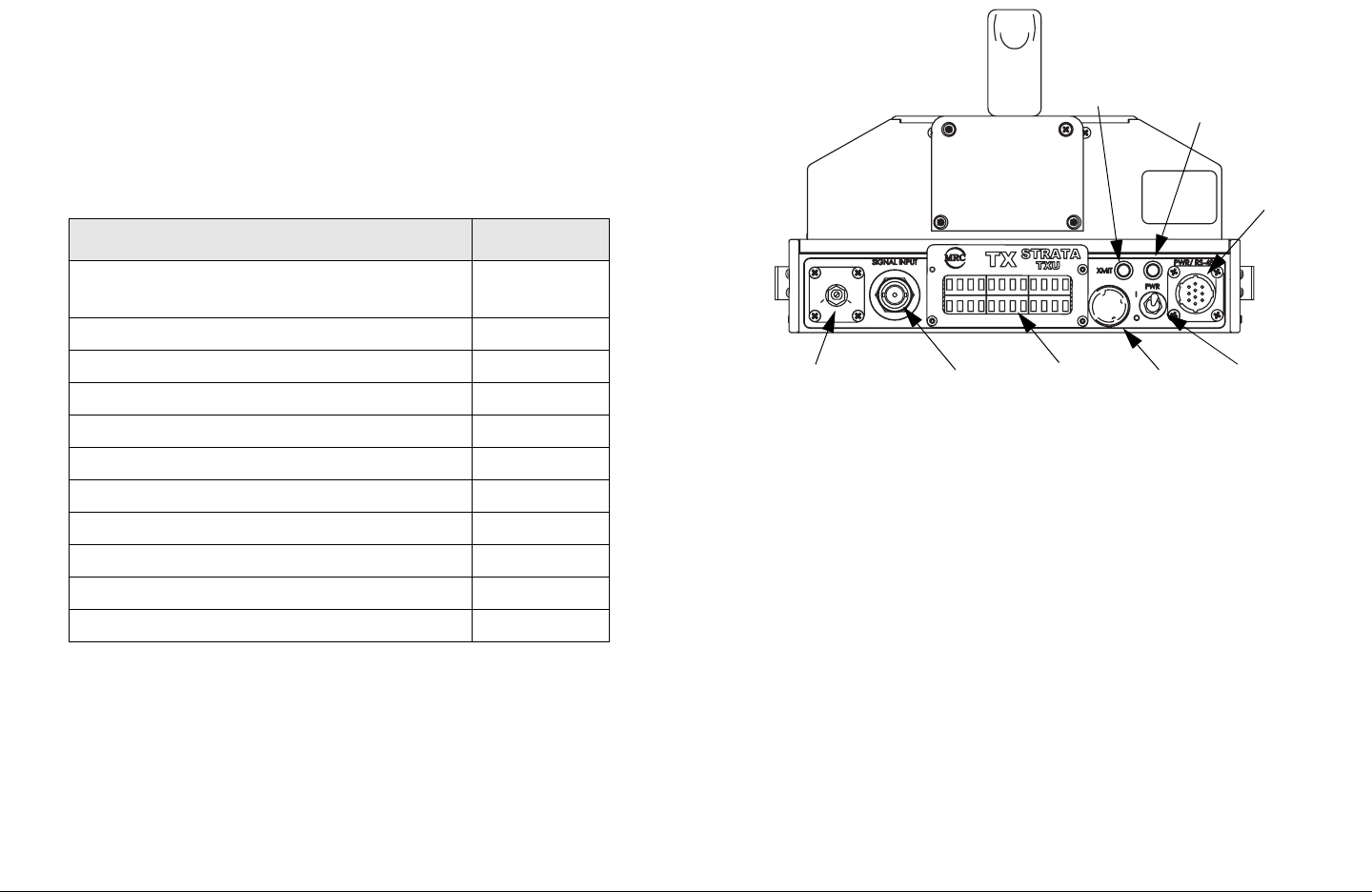
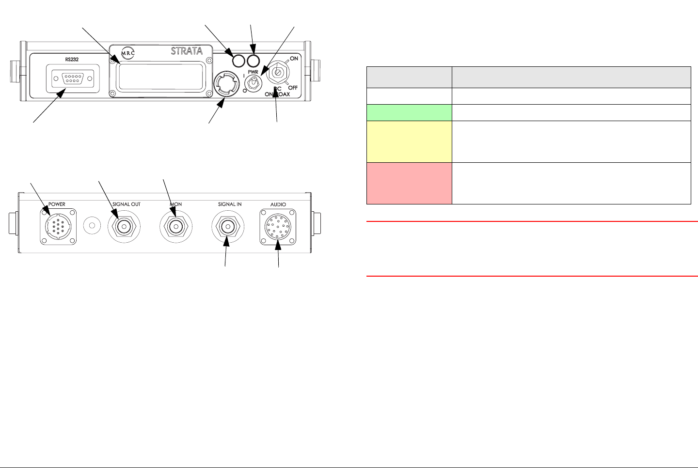
Figure 3-1: TXU Controls, Indicators, and Connectors - Front
View
The TXU is configured using Windows PC-based STRATA TX
Configuration Utility software. For details, see the “Advanced
Operation” Chapter on page 5-1 (part of the STRATA TX System
Technical Reference Manual only).
TXU Front Panel DC ON COAX Switch DC ON COAX
switches are not contained on all configurations of the TXU. For
configuration differences, see “TXU and TCU Configurations”
Chapter on page 2-9.
If your STRATA TX System contains both a TXU and a TCU, the
System allows you to power the TXU using DC power supplied
from the TCU or allows you to power the TCU using DC power
from the TXU. This DC power is superimposed on the coaxial
cable between the TCU and the TXU. This DC power option is
DO NOT
EXCEED
36 VOLTS DC
DC
ON COAX
OFF ON
SIGNAL
INPUT
Connector
Alpha-
numeric
Display
Status
LED
DC ON COAX
Switch or AUDIO
Connector
Control
Switch
Power
Switch
PWR/RS-485
Connector
XMIT
LED
Routine Operation 3-3STRATA TX Operator’s Guide/Tech Ref Manual
used when the TCU and the TXU must be deployed in two
separate locations.
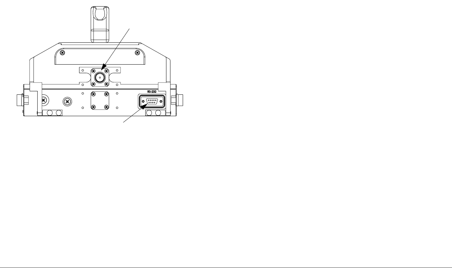
Figure 3-2: TXU Controls, Indicators, and Connectors - Rear
View
When the TCU and TXU are co-located, MRC recommends both
units be powered from the same DC power source.
If your STRATA TX System does not contain a TCU, the DC ON
COAX switch will not be present and an AUDIO connector will
be mounted in place of the switch.
If your STRATA TX System contains both a TXU and a TCU, the
System gives you several ways to control DC power on the
coaxial cable from the TCU to the TXU, depending on the
configurations of your TCU and TXU:
•The DC ON COAX switch on the front panel of the TCU
(See Figure 3-3 on page 3-6) and the DC ON COAX
RF Output
Connector
RS-232
Connector
switch on the front panel of the TXU (See Figure 3-1 on
page 3-2).
•The 75 Ohm Coax option on the Command Screen.
Both control methods must be enabled for DC power to be
operational if your TCU and TXU configurations both contain the
DC ON COAX switches. If the DC ON COAX switch is not
present on your TCU, DC power can only be applied using the
75 Ohm Coax option on the command screen. The TXU DC ON
COAX switch must be set to ON in either situation.
TXU SIGNAL INPUT Connector The BNC INPUT connector
provides the IF or video input to the TXU.
TXU AUDIO Connector AUDIO connectors are not contained
on all configurations of the TXU. For configuration differences,
see “TXU and TCU Configurations” Chapter on page 2-9.
If your TXU contains an AUDIO connector, all audio inputs are
applied to the front panel mounted 10-pin connector.
TXU Alphanumeric Display The TXU contains a two-line by
12-character alphanumeric display. The display works in
conjunction with the control switch to allow you to monitor
system status and to control system settings.
TXU XMIT LED When the TXU control switch is pressed for one
second, the transmitter changes from the standby mode to the
transmit mode or changes from the transmit mode to the standby
mode. When the transmitter is in the transmit mode, the XMIT
LED illuminates blue. When the transmitter is in the standby
mode, the XMIT LED is off.
If your STRATA TX System contains both a TXU and a TCU,
pressing the control switch on either the TXU or TCU will change
the transmitter to the transmit mode or to the standby mode. The
Routine Operation 3-4STRATA TX Operator’s Guide/Tech Ref Manual
XMIT LED on both units will be on or off, depending on the
operating mode.
TXU Status LED Above the PWR switch on both the TXU and
TCU is a multi-color Status LED. The LED indications are as
follows:
WARNING A Major Alarm may also indicate a potential
safety hazard. Shut down the STRATA TX
System and disconnect power.
TXU PWR/RS-485 Connector The TXU PWR/RS-485
connector mounted on the front panel of the unit allows the TXU
to operate on external +28 VDC power sources.
TXU PWR Switch The front panel PWR (power) switch controls
application of DC power to the TXU. If your STRATA TX System
contains both a TXU and an TCU, both PWR switches must be
turned on for the system to function.
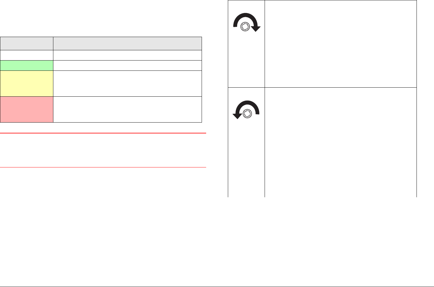
TXU Control Switch Routine operating settings are controlled
by the control switch. Turning the control switch right (cw) or left
(ccw) displays status and settings and pressing it in makes
selections, as described below:
LED Color Meaning
----- Power is not on in that unit.
Green Power is on and no errors are detected.
Amber Minor Alarm - Power is on but some part
of the system reports an abnormal
condition that might impair performance.
Red Major Alarm - Power is on but there is a
failure or error that prevents normal
operation.
Turning the control switch to the right (cw)
displays the Monitor options.
The Monitor options provide current status
of the STRATA TX System, including:
• Frequency Settings
• Mode - Analog or Digital
• Audio Settings
• Video Settings
• System Errors.
Turning the control switch to the left (ccw)
displays the Command options.
The Command options allow control of the
STRATA TX System, including:
• Changing the Preset
• Setting the RF Channel
• Set Power Output
• Select 75 Ohm Coax Power On or Power
Off (Turns power from TCU to TXU or TXU to
TCU on or off if DC power is superimposed on
the coaxial cable between the TCU and the
TXU).
Routine Operation 3-5STRATA TX Operator’s Guide/Tech Ref Manual
TXU RF Output Connector The RF output connector is a type
N connector that allows connection to an antenna.
TXU RS-232 Connector The RS-232 connector provides
connection to a Windows-based PC when using the STRATA TX
Configuration Utility software.
This connector also provides connection to the STRATA
Standard or Aircraft Remote Control Panel when used in mobile
or aircraft operations.
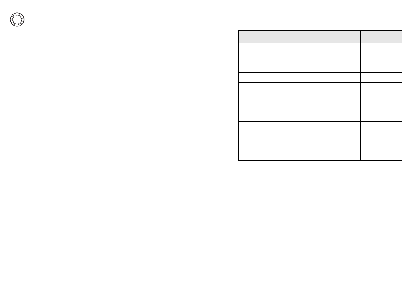
Pressing the control switch causes an
action to occur.
Command Options
• If the displayed setting is Chng Preset, Set
Channel, or Set PowerOut, pressing the
control switch causes the displayed setting to
blink.
Turning the control switch cw or ccw then
displays the other options for that setting.
When the desired option is displayed,
pressing the control switch selects that
option.
• If the displayed setting is 75 Ohm Coax,
pressing the control switch causes the setting
to switch to the other choice (i.e., if 75 Ohm
Coax Power Off is displayed, pressing the
control switch will select 75 Ohm Coax
Power On).
Transmit
• Pressing the control switch for one second
changes the transmitter to the transmit mode
from the standby mode.
• Pressing the control switch for one second
changes the transmitter from the transmit
mode to the standby mode.
3.2.2 TCU Controls, Indicators, and Connectors
Controls, indicators, and connectors contained on the TCU are
identified and described below. Topics covered are as follows:
Each of these controls, indicators, and connectors are described
in the following paragraphs. Controls, indicators, and connectors
contained on the TCU are shown in Figure 3-3 on page 3-6. For
configuration differences in the TCU, see “TXU and TCU
Configurations” on page 2-9.
The TCU is configured using Windows PC-based STRATA TX
Configuration Utility software. For details, see the “Advanced
Operation” Chapter on page 5-1 chapter (part of the STRATA TX
System Technical Reference Manual only).
TCU Alphanumeric Display The TCU contains a two-line by
12-character alphanumeric display. The display works in
conjunction with the control switch to allow you to monitor
system status and to control system settings.
Topic Page
TCU Alphanumeric Display 3-6
TCU XMIT LED 3-6
TCU Status LED 3-6
TCU PWR Switch 3-6
TCU DC ON COAX Switch 3-6
TCU Control Switch 3-7
TCU RS-232 Connector 3-8
TCU POWER Connector 3-8
TCU SIGNAL OUT Connector 3-8
TCU Monitor (MON) Connector 3-8
TCU SIGNAL IN Connector 3-8
TCU AUDIO Connector 3-8
Routine Operation 3-6STRATA TX Operator’s Guide/Tech Ref Manual
Figure 3-3: TCU Controls, Indicators, and Connectors
TCU XMIT LED When the TCU control switch is pressed for one
second, the transmitter changes from the standby mode to the
transmit mode or from the transmit mode to the standby mode.
When the transmitter is in the transmit mode, the XMIT LED
illuminates blue. When the transmitter is in the standby mode,
the XMIT LED is off.
If your STRATA TX System contains both a TXU and a TCU,
pressing the Control switch on either the TXU or TCU will
change the transmitter to the transmit mode or to the standby
TCU
TX
XMIT
(Rear View)
(Front View) DC ON COAX
Switch
SIGNAL IN
Connector
Monitor (MON)
Connector
SIGNAL OUT
Connector
POWER
Connector
RS-232
Connector
AUDIO
Connector
Alphanumeric
Display
Control
Switch
PWR
Switch
Status
LED
XMIT
LED
mode. The XMIT LED on both units will be on or off, depending
on the operating mode.
TCU Status LED Above the PWR switch on both the TXU and
TCU is a multi-color Status LED. The LED indications are as
follows:
WARNING A Major Alarm may also indicate a potential
safety hazard. Shut down the STRATA TX
System and disconnect power.
TCU PWR Switch The front panel PWR (power) switch controls
application of DC power to the TCU. If your STRATA TX System
contains both a TXU and an TCU, both PWR switches must be
turned on for the system to function.
TCU DC ON COAX Switch DC ON COAX switches are not
contained on all configurations of the TCU. For configuration
differences, see “TXU and TCU Configurations” on page 2-9.
If your STRATA TX System contains both a TXU and a TCU, the
System allows you to power the TXU using DC power supplied
from the TCU or to power the TCU using DC power from the
LED Color Meaning
----- Power is not on in that unit.
Green Power is on and no errors are detected.
Amber Minor Alarm - Power is on but some part
of the system reports an abnormal
condition that might impair performance.
Red Major Alarm - Power is on but there is a
failure or error that prevents normal
operation.
Routine Operation 3-7STRATA TX Operator’s Guide/Tech Ref Manual
TXU. This DC power is superimposed on the coaxial cable
between the TCU and the TXU. This DC power option is used
when the TCU and the TXU must be deployed in two separate
locations.
When the TCU and TXU are co-located, MRC recommends both
units be powered from the same DC power source.
If your STRATA TX System does not contain a TXU, the DC ON
COAX switch may not be present. If the switch is present, it
should be set to the OFF position.
If your STRATA TX System contains both a TXU and a TCU, the
System gives you several ways to control DC power on the
coaxial cable between the TCU and the TXU, depending on the
configurations of your TCU and TXU:
•The DC ON COAX switch on the front panel of the TCU
(See Figure 3-3 on page 3-6) and the DC ON COAX
switch on the front panel of the TXU (See Figure 3-1 on
page 3-2).
•The 75 Ohm Coax option on the Command Screen.
Both control methods must be enabled for DC power to be
operational if your TCU and TXU configurations contain the DC
ON COAX switches. If the DC ON COAX switch is not present
on your TCU, DC power can only be applied using the 75 Ohm
Coax option on the command screen. The TXU DC ON COAX
switch must be set to ON in either situation.
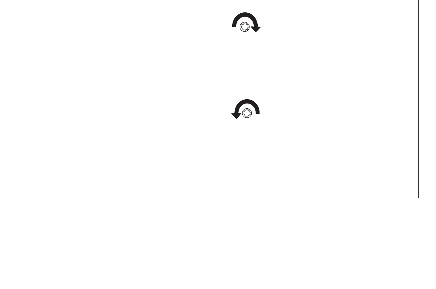
TCU Control Switch Routine operating settings are controlled
by the control switch. Turning the control switch right (cw) or left
(ccw) displays status and settings and pressing it in makes
selections, as described below:
Turning the control switch to the right (cw)
displays the Monitor options.
The Monitor options provide current status
of the STRATA TX System, including:
• Frequency Settings
• Mode - Analog or Digital
• Audio Settings
• Video Settings
• System Errors.
Turning the control switch to the left (ccw)
displays the Command Screens.
The Command Screens allow control of the
STRATA TX System, including:
• Changing the Preset
• Setting the RF Channel
• Set Power Output
• Select 75 Ohm Coax Power On or Power
Off (Turns power from TCU to TXU or TXU to
TCU on or off if DC power is superimposed on
the coaxial cable between the TCU and the
TXU).

Routine Operation 3-8STRATA TX Operator’s Guide/Tech Ref Manual
TCU RS-232 Connector The RS-232 connector provides
connection to a Windows-based PC when using the STRATA TX
Configuration Utility software.
This connector also provides connection to the STRATA
Standard or Aircraft Remote Control Panel when used in mobile
or aircraft operations.
Pressing the control switch causes an
action to occur.
Command Options
• If the displayed setting is Chng Preset, Set
Channel, or Set PowerOut, pressing the
control switch causes the displayed setting to
blink.
Turning the control switch cw or ccw then
displays the other options for that setting.
When the desired option is displayed,
pressing the control switch selects that
option.
• If the displayed setting is 75 Ohm Coax,
pressing the control switch causes the setting
to switch to the other choice (i.e., if 75 Ohm
Coax Power Off is displayed, pressing the
control switch will select 75 Ohm Coax
Power On).
Transmit
• Pressing the control switch for one second
changes the transmitter to the transmit mode
from the standby mode.
• Pressing the control switch for one second
changes the transmitter from the transmit
mode to the standby mode.
TCU POWER Connector The TCU POWER connector
mounted on the rear panel of the unit allows the TCU to operate
on external +28 VDC power sources.
TCU SIGNAL OUT Connector The TNC type SIGNAL OUT
connector provides ASI, CODFM - IF, IF, or IF composite video
output signals, depending upon the options contained in the unit.
In addition, if the TCU is used in conjunction with a separately
located TXU, DC power to or from the TXU is superimposed on
the output signal coaxial cable between the TXU and TCU.
TCU Monitor (MON) Connector If your TCU has COFDM/
MPEG installed, this rear panel output connector can be
configured (when operating in the digital mode) to provide either:
•70 MHz IF
• ASI (output of COFDM modulator, before decoding)
If your TCU is equipped with an analog modulator, this connector
provides only the 70 MHz IF signal output.
TCU SIGNAL IN Connector Video connections are made to
the BNC SIGNAL IN connector. Video input selections are
made by selecting Presets from the front panel control switch.
Presets are created using the STRATA TX Configuration Utility
software. For more information, see the “Advanced Operation”
Chapter on page 5-1 (part of the STRATA TX System Technical
Reference Manual only).
TCU AUDIO Connector Audio connections are made to the
rear panel AUDIO connector.
3.2.3 ACU Controls, Indicators, and Connectors
Controls, indicators, and connectors contained on the optional
ACU are identified and described below. Topics covered are as
follows:
Routine Operation 3-9STRATA TX Operator’s Guide/Tech Ref Manual
Each of the controls, indicators, and connectors are described in
more detail in the following paragraphs. Controls, indicators, and
connectors contained on the ACU are shown in Figure 3-4.
ACU AC INPUT Connector The AC INPUT connector
mounted on the rear panel of the unit provides external AC
power to the unit.
ACU POWER Switch The front panel POWER switch controls
application of DC power to the DC OUTPUT connector. When
the switch is set to I (on), DC power is present at the DC
OUTPUT connector. When set to 0 (off), no output DC power is
present at the DC OUTPUT connector.
ACU Power LED The power LED is on when the POWER
switch is set to I (on), indicating DC power is available at the DC
OUTPUT connector. The indicator is off when the POWER
switch is set to 0 (off).
ACU DC OUTPUT Connector The DC OUTPUT connector
mounted on the front panel of the unit provides +28 VDC power
to the TCU and/or TXU.
ACU FUSE The fuse provides overload protection for AC input
power.
Topic Page
ACU AC INPUT Connector 3-9
ACU Power LED 3-9
ACU Power LED 3-9
ACU DC OUTPUT Connector 3-9
ACU FUSE 3-9
Figure 3-4: ACU Controls, Indicators, and Connectors
3.2.4 STRATA Standard Remote Control Panel
Controls, Indicators, and Connectors
For controls, indicators, and connectors contained on the
optional Standard Remote Control Panel, refer to the STRATA
Remote Control Panel Operator’s Guide, Document number
400489.
3.2.5 STRATA Aircraft Remote Control Panel
Controls, Indicators, and Connectors
For controls, indicators, and connectors contained on the
optional STRATA Aircraft Remote Control Panel, refer to the
STRATA Aircraft Remote Control Panel Operator’s Guide,
Document number 400490.
OUTPUT
OUTPUT
< >
< >
DC
DC
FUSE
POWER
Switch
Power
LED
DC OUTPUT
Connector
AC INPUT
Connector
Routine Operation 3-10STRATA TX Operator’s Guide/Tech Ref Manual
3.3 Preparing for Operation
Each installation or deployment will have its own specific tasks
according to the application and the installed hardware.
3.3.1 Mobile Installation
For mobile applications such as aircraft or vehicle, the STRATA
TX System is usually mounted in a bulkhead or compartment
using an MRC Fixed Mounting Bracket. See Figure 3-5.
Mounting brackets are available to mount from one to three
units.
Figure 3-5: Fixed Mounting Bracket
The cabling is permanently installed and power comes from
aircraft (or vehicle) power.
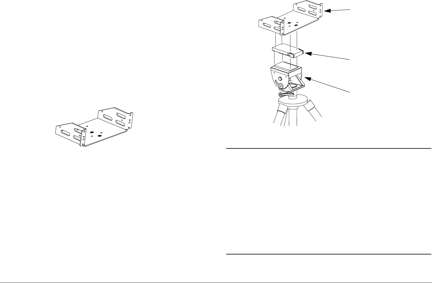
3.3.2 Portable Deployment
For situations where you need to mount a STRATA TX System
and its Fixed Mounting Bracket to an MRC tripod, MRC also
offers a Quick Release. See Figure 3-6.
For situations where you are mounting to another type of tripod
that doesn’t directly accept the Quick Release, consult with MRC
or your tripod manufacturer. MRC has Dovetail Adapter Plates
that will convert some types of tripods to accept the Quick
Release.
Figure 3-6: Fixed Mounting Bracket on Tripod
Note The versatility of the Quick Release Mount and
mating Dovetail Adapter Plate allows the Dovetail
Adapter Plate to be attached to the bottom of the
Universal Mounting Bracket and the Quick Release
Mount to be attached to a non-MRC tripod, or vice
versa.
For optional methods of attaching your STRATA TX
System to a non-MRC tripod, refer to the
“Installation” Chapter on page 6-1 (part of the
STRATA TX System Technical Reference Manual
only)
For portable applications where the STRATA TX System will be
moved from place to place and set up each time, the system will
Fixed Mounting
Bracket
Quick Release
MRC Tripod
(Typical)
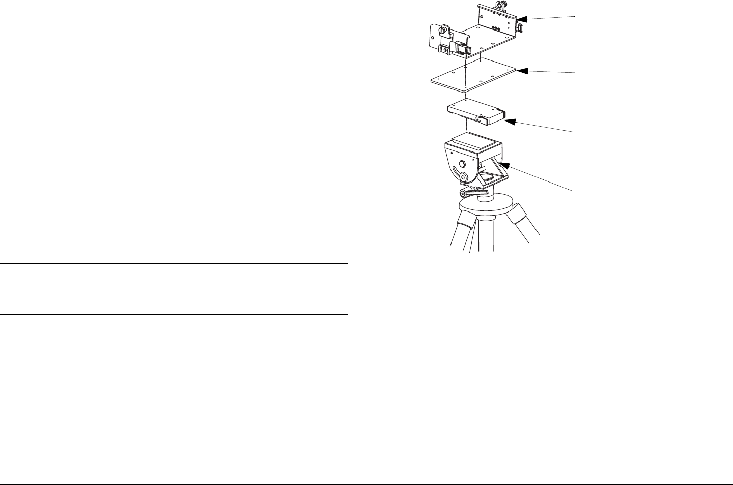
Routine Operation 3-11STRATA TX Operator’s Guide/Tech Ref Manual
usually be mounted in an MRC Universal Mounting Bracket. The
Universal Mounting Bracket will then be attached to a Quick
Release for easy mounting on an MRC tripod. See Figure 3-7.
Universal Mounting Brackets are required for each unit in the
STRATA TX System, i.e., TXU, TCU, and an optional ACU.
For applications using multiple units such as a TXU, TCU, and
an ACU, a Mounting Plate is also used to provide additional
stiffness. The Mounting Plate typically remains attached
between the Universal Mounting Bracket and the Quick Release.
The cabling between TX System units is also typically left in
place. The power, antenna and audio/video connections are
usually removed at the end of each deployment.
For portable deployment situations where you are mounting to
another type of tripod that doesn’t directly accept the Quick
Release, consult with MRC or your tripod manufacturer. MRC
has Dovetail Adapter Plates that will convert some types of
tripods to accept the Quick Release.
Note The procedures and illustrations contained in the
following paragraph are typical, reflecting use of an
MRC tripod.
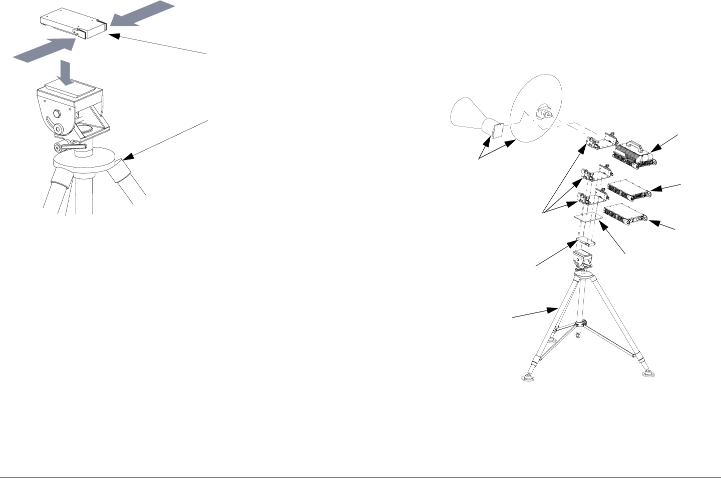
Mounting to the Tripod Following are the general steps to
mount a STRATA TX System to an MRC Tripod. These steps
assume the TX System is already assembled into its Universal
Mounting Bracket(s), and that the Mounting Plate and Quick
Release are attached.
Figure 3-7: Universal Mounting Bracket on Tripod
1. Attach the TX System to the Tripod using the Quick
Release as shown in Figure 3-8 on page 3-12.
2. Attach the antenna to the TXU using the Antenna Lock
Plate, or connect a coaxial cable from the TXU to the
antenna. See Figure 3-9 on page 3-12.
Universal Mounting
Bracket
Mounting Plate
(for TXU, TCU, and ACU)
Quick Release
MRC Tripod
(Typical)
Routine Operation 3-12STRATA TX Operator’s Guide/Tech Ref Manual
Figure 3-8: Attaching Quick Release to Tripod
3. If you have both an TXU and a TCU, be sure they are
connected to each other via coaxial cable.
If you are unsure of the connections, refer to the
“Installation” Chapter on page 6-1 (part of the STRATA
TX System Technical Reference Manual only).
4. Connect the STRATA TXU (and TCU, if present) to DC
power of the correct voltage and polarity.
If you’re using a STRATA ACU, connect the AC input
to AC power and connect the DC output to the TXU
and TCU.
If you are unsure of the power requirements or the
connections, refer to the “Installation” Chapter on
Quick Release
Tripod
page 6-1 (part of the STRATA TX System Technical
Reference Manual only).
5. Connect the TXU (or TCU) inputs to your audio and
video equipment.
Figure 3-9: Complete Tripod Installation
3.3.3 Powering the STRATA TX System
The STRATA TX System will be in one of two configurations
which provide different options for controlling application of DC
power between units. Model variations are as follows:
Universal
Mounting
Brackets
Antenna
(2 Options
Shown)
Quick
Release
TXU
TCU
ACU
Mounting
Plate
Tripod
(Typical)

Routine Operation 3-13STRATA TX Operator’s Guide/Tech Ref Manual
Superimposing DC Power In this configuration, DC power is
superimposed with the IF signals between units and there is no
manual control of DC power from the TCU. The DC power is
superimposed on the coaxial cable between the TCU and the
TXU.
To turn DC power on and off, the operator uses the TCU and
TXU front panel PWR switches and either the TCU or TXU
control switch and alphanumeric display menus. The TXU DC
ON COAX switch must be set to ON.
Superimposing DC Power with Manual Control In this
configuration, DC power superimposed on the IF signals
between the units is manually controlled. The operator can
manually turn DC power on or off to the TXU from the TCU or to
the TCU from the TXU using DC ON COAX switches and TCU or
TXU front panel control switches and alphanumeric display
menus.
The DC ON COAX switches provide the manual control and
must be set to ON to allow application of DC power to the TXU ,
and TCU using the control switches and alphanumeric display
menus.
Powering STRATA TX Systems The method you use to power
up your STRATA TX System will vary, depending upon the
following:
• The model of your STRATA TX System, whether or not
you have DC power manual override control.
• The transmitter configuration, whether you are using a
single TCU, a single TXU, or a TCU and TXU
• Whether the TCU and TXU are to be co-located or
physically separated over some distance.
• Whether your STRATA TX System contains the optional
AC to DC Power Converter (ACU).
3.3.4 Single TCU Power Up and Power Down
If your STRATA TX System consists of a single TCU, perform the
following steps:
CAUTION To avoid possible damage, turn off DC
Power on the coax before connecting any
test equipment.
Power Up
1. Verify the power cable is properly connected to the
TCU rear panel POWER connector.
2. Verify all coaxial cables and connectors have been
properly connected.
3. Connect the TCU to DC power of the correct voltage
and polarity.
If you are unsure of the power requirements or the
connections, refer to the “Installation” Chapter on
page 6-1 (Part of the STRATA TX System Technical
Reference Manual only).
If the TCU is powered from the optional STRATA ACU,
connect the ACU input to AC power and verify the
TCU power cable is connected to the ACU DC
OUTPUT connector. Set the ACU power switch to I
(on) and verify the ACU power LED is on.
If the TCU is powered from a source other than an
ACU, turn that power source on.
4. Set the TCU PWR switch to I (on).

Routine Operation 3-14STRATA TX Operator’s Guide/Tech Ref Manual
5. The normal power-up sequence is as follows:
- The Status LED above the PWR switch should
illuminate and should change colors from red, to
green, to amber, and finally remain green.
- The alphanumeric display should light up and quickly
display a self-test screen, then the version of the
installed firmware, and finally the Main Screen.
Some typical screens are shown in Figure 3-10. The
exact screens will vary depending on installed
hardware.
- The TCU will typically power up using the last settings
in use when power was turned off.
- If the TCU does not power up normally, refer to the
“Troubleshooting” Chapter on page 4-1.
Figure 3-10: Typical TCU Power Up Screens - Single TCU
Power Down
1. Set the TCU PWR switch to 0 (off).
2. If the TCU is powered from the optional ACU, set the
ACU power switch to 0 (off).
STRATA TX
V X.X.X
Preset 1
0.00W
Radio Version
Main Screen
If the TCU is powered from a source other than an
ACU, turn that power source off.
3.3.5 Single TXU Power up and Power Down
If your STRATA TX System consists of a single TXU, perform the
following steps:
CAUTION To avoid possible damage, turn off DC
Power on the coax before connecting any
test equipment.
Power Up
1. Verify the power cable is properly connected to the
TXU front panel POWER connector.
2. Verify all coaxial cables and connectors have been
properly connected.
3. Connect the TXU to DC power of the correct voltage
and polarity.
If you are unsure of the power requirements or the
connections, refer to the “Installation” Chapter on
page 6-1 (Part of the STRATA TX System Technical
Reference Manual only).
If the TXU is powered from the optional STRATA ACU,
connect the ACU input to AC power and verify the
TXU power cable is connected to the ACU DC
OUTPUT connector. Set the ACU power switch to I
(on) and verify the ACU power LED is on.
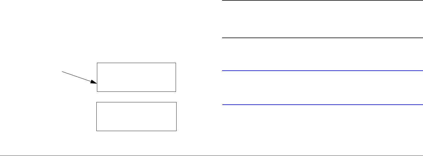
Routine Operation 3-15STRATA TX Operator’s Guide/Tech Ref Manual
If the TXU is powered from a source other than an
ACU, turn that power source on.
4. Set the TXU PWR switch to I (on).
5. The normal power-up sequence is as follows:
- The Status LED above the PWR switch should
illuminate and should change colors from red, to
green, to amber, and finally remain green.
- The alphanumeric display should light up and quickly
display a self-test screen, then the version of the
installed firmware, and finally the Main Screen.
Some typical screens are shown in Figure 3-11. The
exact screens will vary depending on installed
hardware.
- The TXU will typically power up using the last settings
in use when power was turned off.
- If the TXU does not power up normally, refer to the
“Troubleshooting” Chapter on page 4-1.
Figure 3-11: Typical TXU Power Up Screens - Single TXU
STRATA TX
V X.X.X
Preset 1
0.00W
Radio Version
Main Screen
Power Down
1. Set the TXU PWR switch to 0 (off).
2. If the TXU is powered from the optional ACU, set the
ACU power switch to 0 (off).
If the TXU is powered from a source other than an
ACU, turn that power source off.
3.3.6 TXU and TCU Power Up and Power Down -
Co-Located
If your STRATA TX System consists of a co-located TXU and a
TCU, it is recommended that both the TCU and TXU be powered
from the same DC power supply in lieu of using superimposed
DC power on the coaxial cable between the TCU and the TXU.
Note The following procedure reflects use of a single DC
power source for both the TXU and TCU in lieu of
using superimposed DC power on the coaxial
cable between the TCU and the TXU.
Perform the following steps to power up or power down a co-
located TX System:
CAUTION To avoid possible damage, turn off DC
Power on the coax before connecting any
test equipment.

Routine Operation 3-16STRATA TX Operator’s Guide/Tech Ref Manual
Power Up
1. Verify the power cable is properly connected to the
TCU rear panel POWER connector.
2. Verify the power cable is properly connected to the
TXU front panel POWER connector.
Note If your TCU does not have a DC ON COAX
switch, go to step 4.
3. Turn the recessed DC ON COAX switch on the front
panel of the TCU until the screw slot of the switch
points to OFF.
4. Turn the recessed DC ON COAX switch on the front
panel of the TXU until the screw slot of the switch
points to OFF.
5. Verify all coaxial cables and connectors have been
properly connected.
6. Connect the TCU and TXU to DC power of the correct
voltage and polarity.
If you are unsure of the power requirements or the
connections, refer to the “Installation” Chapter on
page 6-1 (Part of the STRATA TX System Technical
Reference Manual only).
If the TCU and TXU are both powered from the
optional STRATA ACU, connect the ACU input to AC
power and verify the TCU and TXU branched power
cable is connected to the ACU DC OUTPUT
connector. Set the ACU power switch to I (on) and
verify the ACU power LED is on.
If the TCU and TXU are powered from a source other
than an ACU, turn that power source on.
7. Set the TCU PWR switch to I (on).
8. The normal power-up sequence is as follows:
- The Status LED above the PWR switch should
illuminate and should change colors from red, to
green, to amber, and finally remain green.
- The alphanumeric display should light up and quickly
display a self-test screen, then the version of the
installed firmware, and finally the Main Screen.
Some typical screens are shown in Figure 3-12. The
exact screens will vary depending on installed
hardware.
- The TCU will typically power up using the last settings
in use when power was turned off.
- If the TCU does not power up normally, refer to the
“Troubleshooting” Chapter on page 4-1.
Figure 3-12: Typical TCU Power Up Screens - Co-Located
TXU and TCU
STRATA TX
V X.X.X
Preset 1
0.00W
Radio Version
Main Screen
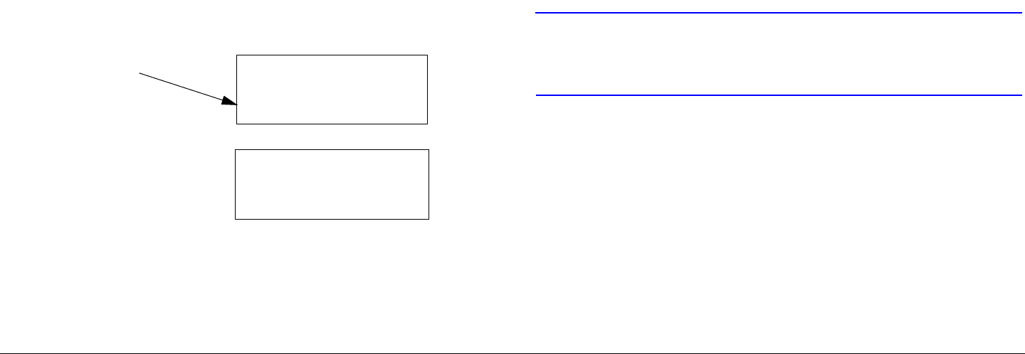
Routine Operation 3-17STRATA TX Operator’s Guide/Tech Ref Manual
9. Set the TXU PWR switch to I (on).
10. The normal power-up sequence is as follows:
- The Status LED above the PWR switch should
illuminate and should change colors from red, to
green, to amber, and finally remain green.
- The alphanumeric display should light up and quickly
display a self-test screen, then the version of the
installed firmware, and finally the Main Screen.
Some typical screens are shown in Figure 3-13. The
exact screens will vary depending on installed
hardware.
- The TXU will typically power up using the last settings
in use when power was turned off.
If the TXU does not power up normally, refer to the
“Troubleshooting” Chapter on page 4-1.
Figure 3-13: Typical TXU Power Up Screens - Co-Located
TXU and TCU
Power Down
1. Set the TXU PWR switch to 0 (off).
2. Set the TCU PWR switch to 0 (off).
STRATA TX
V X.X.X
Preset 1
0.00W
Radio Version
Main Screen
3. If the TXU and TCU are powered from the optional
ACU, set the ACU power switch to 0 (off).
If the TCU and TXU are powered from a source other
than an ACU, turn that power source off.
3.3.7 TXU and TCU Power Up and Power Down -
Separate Locations
If your STRATA TX System consists of a TXU and a TCU and the
TCU is located in a separate location from the TXU, the TXU will
be powered using the superimposed DC power on the coaxial
cable between the TCU and the TXU or the TCU will be powered
using DC power superimposed on the coaxial cable from the
TXU.
Perform the following steps to power up or power down a
separately located TXU and TCU TX System:
CAUTION To avoid possible damage, turn off DC
Power on the coax before connecting any
test equipment.
Power Up
1. Verify the power cable is properly connected to the
TCU rear panel POWER connector.
Note If your TCU does not have a DC ON COAX
switch, go to step 3.
2. Turn the recessed DC ON COAX switch on the front
panel of the TCU until the screw slot of the switch
points to ON.
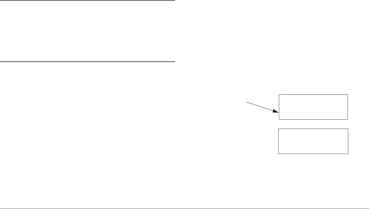
Routine Operation 3-18STRATA TX Operator’s Guide/Tech Ref Manual
3. Turn the recessed DC ON COAX switch on the front
panel of the TXU until the screw slot of the switch
points to ON.
4. Verify all coaxial cables and connectors have been
properly connected.
Note When the TCU and TXU are mounted in separate
locations, it is recommended that DC input power
be connected to the TXU.
Since either unit may be powered from the other
unit via DC power superimposed on the coaxial
cable between the units, DC input power may
therefore be applied to either the TXU or the TCU.
5. Connect the TCU or TXU to DC power of the correct
voltage and polarity.
If you are unsure of the power requirements or the
connections, refer to the “Installation” Chapter on
page 6-1 chapter (Part of the STRATA TX System
Technical Reference Manual only).
If the TCU/TXU is powered from the optional STRATA
ACU, connect the ACU input to AC power and verify
the TCU/TXU power cable is connected to the ACU
DC OUTPUT connector. Set the ACU power switch to
I (on) and verify the ACU power LED is on.
If the TCU is powered from a source other than an
ACU, turn that power source on.
6. Set the TCU PWR switch to I (on).
7. The normal power-up sequence is as follows:
- The Status LED above the PWR switch should
illuminate and should change colors from red, to
green, to amber, and finally remain green.
- The alphanumeric display should light up and quickly
display a self-test screen, then the version of the
installed firmware, and finally the Main Screen.
Some typical screens are shown in Figure 3-14. The
exact screens will vary depending on installed
hardware.
- The TCU will typically power up using the last settings
in use when power was turned off.
- If the TCU does not power up normally, refer to the
“Troubleshooting” Chapter on page 4-1.
Figure 3-14: Typical TCU Power Up Screens - Separately
Located TXU and TCU
8. Rotate the TCU control switch ccw until the 75 Ohm
Coax option (Figure 3-15 on page 3-19) is displayed
on the alphanumeric display.
STRATA TX
V X.X.X
Preset 1
0.00W
Radio Version
Main Screen
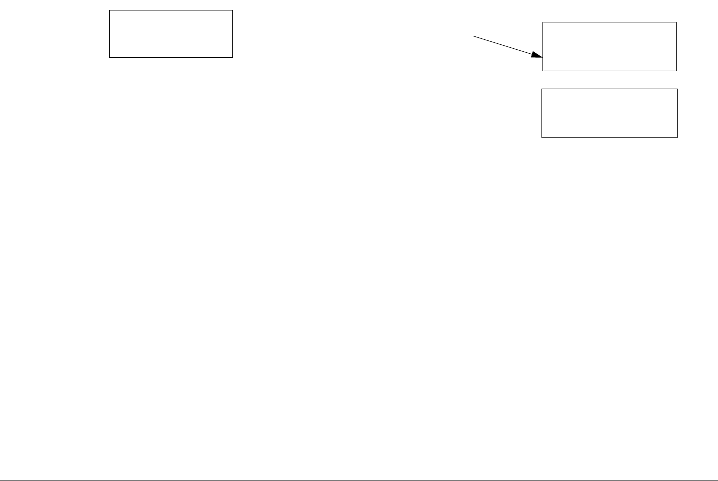
Routine Operation 3-19STRATA TX Operator’s Guide/Tech Ref Manual
Figure 3-15: 75 Ohm Coax Option
9. Press control switch to change Power Off to read
Power On, as required.
10. Set the TXU PWR switch to I (on).
11. The normal power-up sequence is as follows:
- The Status LED above the PWR switch should
illuminate and should change colors from red, to
green, to amber, and finally remain green.
- The alphanumeric display should light up and quickly
display a self-test screen, then the version of the
installed firmware, and finally the Main Screen.
Some typical screens are shown in Figure 3-16. The
exact screens will vary depending on installed
hardware.
- The TXU will typically power up using the last settings
in use when power was turned off.
- If the TXU does not power up normally, refer to the
“Troubleshooting” Chapter on page 4-1.
75 Ohm Coax
Power Off
Figure 3-16: Typical TXU Power Up Screens - Co-Located
TXU and TCU
Power Down
1. Set the TXU PWR switch to 0 (off).
2. Set the TCU PWR switch to 0 (off).
3. If the TCU/TXU is powered from the optional ACU, set
the ACU power switch to 0 (off).
If the TCU/TXU is powered from a source other than
an ACU, turn that power source off.
STRATA TX
V X.X.X
Preset 1
0.00W
Radio Version
Main Screen

Routine Operation 3-20STRATA TX Operator’s Guide/Tech Ref Manual
3.4 Using the STRATA TX Screens
As you use the STRATA TX System, you will interact extensively
with the TXU and/or TCU screens. Following are some points to
make this easier.
Main Screen The Main Screen is your starting point for
navigating through the Monitor and Control option screens. The
Main screen provides the current values of the Preset selected
and the selected Preset output power level.
When the STRATA TX System completes its power-up
sequence, it will display the Main Screen. A typical Main screen
is shown in Figure 3-17.
Figure 3-17: Typical STRATA TX Main Screen
Accessing the Main Screen You can access the Main screen
at any time by scrolling to the end of the screens you are viewing
(either Monitor or Control). Your next click of the control switch
will bring up the Main screen.
Accessing the Monitor Screen You can access the Monitor
option screens at any time by turning the control switch
clockwise (cw).
Accessing the Control Screen You can access the Control
option screens at any time by turning the control switch counter-
clockwise (ccw).
Preset 3
. W
Currently
Selected
Preset
Output Power
Level
Default to Main Screen If you do not turn or push the control
switch for a period of about 7 seconds, the display will default to
the Main screen.
If you turn the control switch within those 7 seconds, you will
continue scrolling within that set of screens (Monitor or Control).
Unit vs.System Control If you’re using a standalone TXU or
TCU, the menus and options that appear on the display will be
based on the hardware option(s) installed in that individual unit.
When you connect your TCU and TXU, the two units
automatically detect what hardware is installed in each unit, and
automatically configure the menus and options to match the
installed hardware. The connected STRATA TX System then
allows you to control the entire system from either the TXU or the
TCU front panel.
3.5 TXU and/or TCU Monitoring
Operations
The STRATA TX System Presets are set to six possible modes
of operation, based on the options contained in your TXU and/or
TCU. These operating modes are established using the STRATA
TX Configuration Utility software. The operating mode options
available via the Configuration Utility software are as follows:
• MPEG Only ASI Out (MPEG Output mode) (Standalone
TCU Operation Only)
• External 70MHz IF In (Ext IF Input mode)
• MPEG/COFDM IF Out (COFDM - IF mode)
• COFDM Only - ASI In (COFDM ASI In mode)
• Analog IF Output (Analog - IF mode)
• DVB-S (Satellite) (DVB-S mode) (Standalone TCU

Routine Operation 3-21STRATA TX Operator’s Guide/Tech Ref Manual
Operation Only)
The options displayed on the Monitor Screens are in bold fonts.
Once the STRATA TX System is set up and powered up, you will
be able to check its configuration and monitor its operation.
The following sections describe how to use the Monitor Screens
and how to monitor the quality of the microwave link.
Here are the tasks described:
Topic Page
Using the Monitor Screens in
MPEG Output Mode
3-21
Using the Monitor Screens in Ext
IF Input Mode
3-23
Using the Monitor Screens in
COFDM - IF Mode
3-24
Using the Monitor Screens in
COFDM ASI In Mode
3-25
Using the Monitor Screens in
Analog - IF Mode
3-26
Using the Monitor Screens in DVB-
S Mode
3-27
3.5.1 Using the Monitor Screens in MPEG Output
Mode
When the STRATA TX System Preset selected is operating in
the MPEG Output mode, a DVB ASI transport stream is
supplied to the signal output connector and the monitor output
connector. The MPEG Output mode is only available when the
TCU is operated in a standalone configuration.
See Figure 3-18 on page 3-22 for the MPEG Output Monitor
Menu Map.
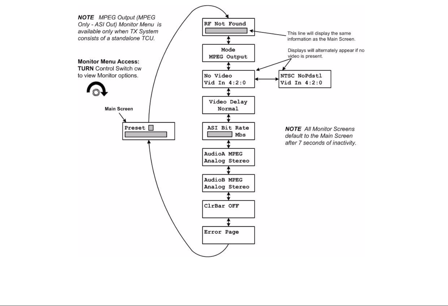
Routine Operation 3-22STRATA TX Operator’s Guide/Tech Ref Manual
Figure 3-18: MPEG Output Monitor Menu Map
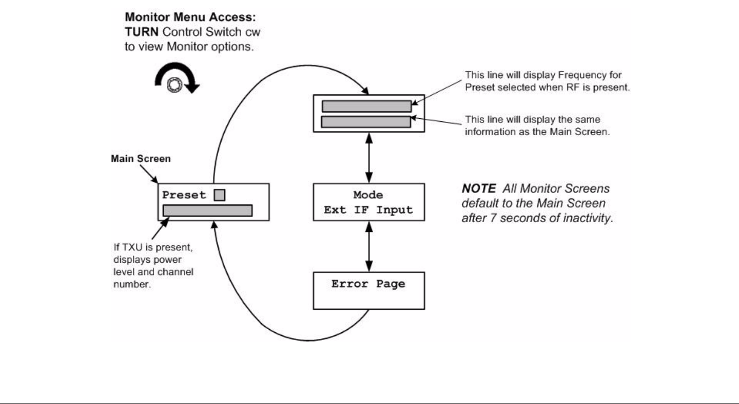
Routine Operation 3-23STRATA TX Operator’s Guide/Tech Ref Manual Routine Operation 3-23STRATA TX Operator’s Guide/Tech Ref Manual
3.5.2 Using the Monitor Screens in Ext IF Input
Mode
When the STRATA TX System is operating in the Ext IF Input
mode, the 70 MHz IF input signal from the input connector is
routed through the TCU to the TXU (if present).
See Figure 3-19 for the Ext IF Monitor Map.
Figure 3-19: Ext IF Input Monitor Map
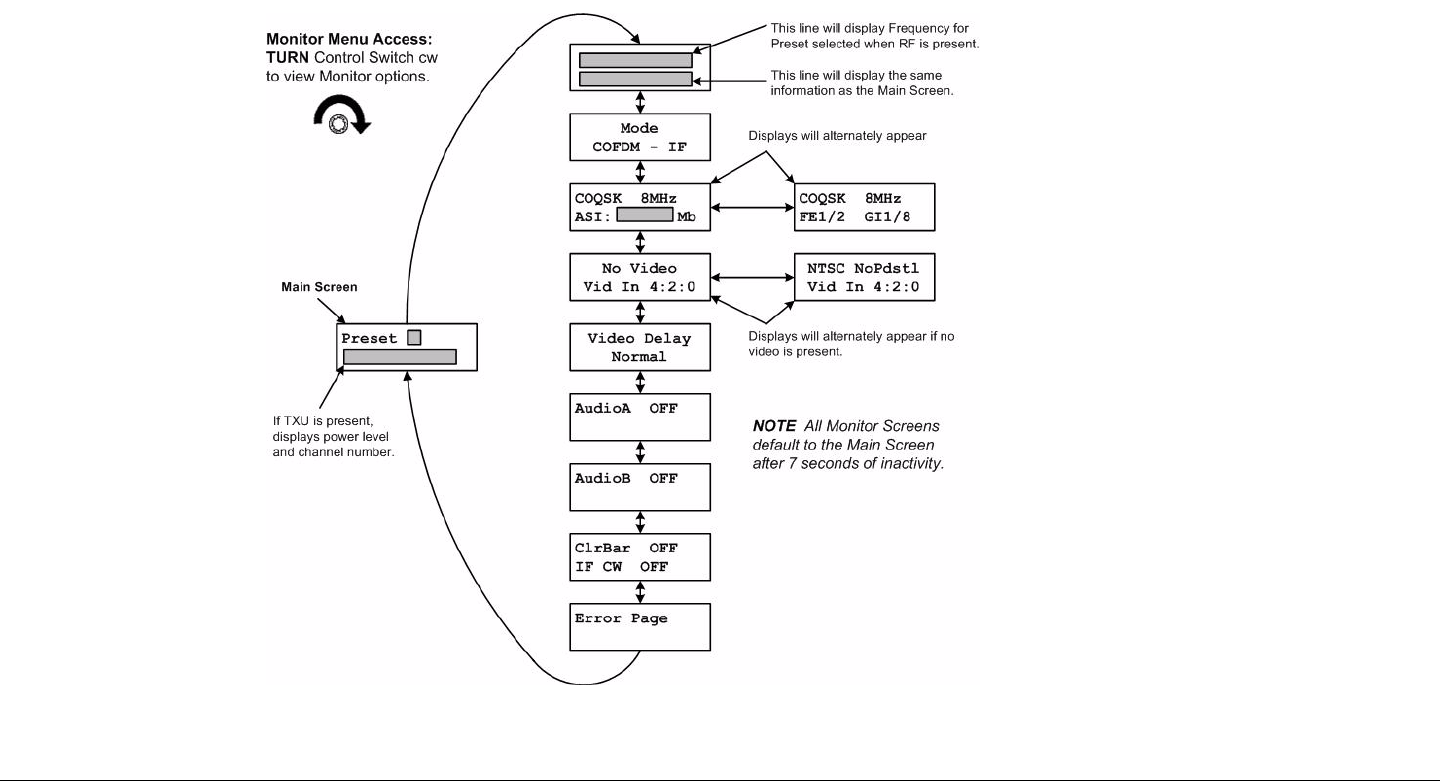
Routine Operation 3-24STRATA TX Operator’s Guide/Tech Ref Manual Routine Operation 3-24STRATA TX Operator’s Guide/Tech Ref Manual
3.5.3 Using the Monitor Screens in COFDM - IF
Mode
When the STRATA TX System is operating in the COFDM - IF
mode, 70 MHz COFDM IF output from the internal COFDM/
MPEG board is supplied to the output and monitor ports and to
the TXU, if present.
See Figure 3-20 for the COFDM - IF Monitor Menu Map.
Figure 3-20: COFDM - IF Monitor Menu Map
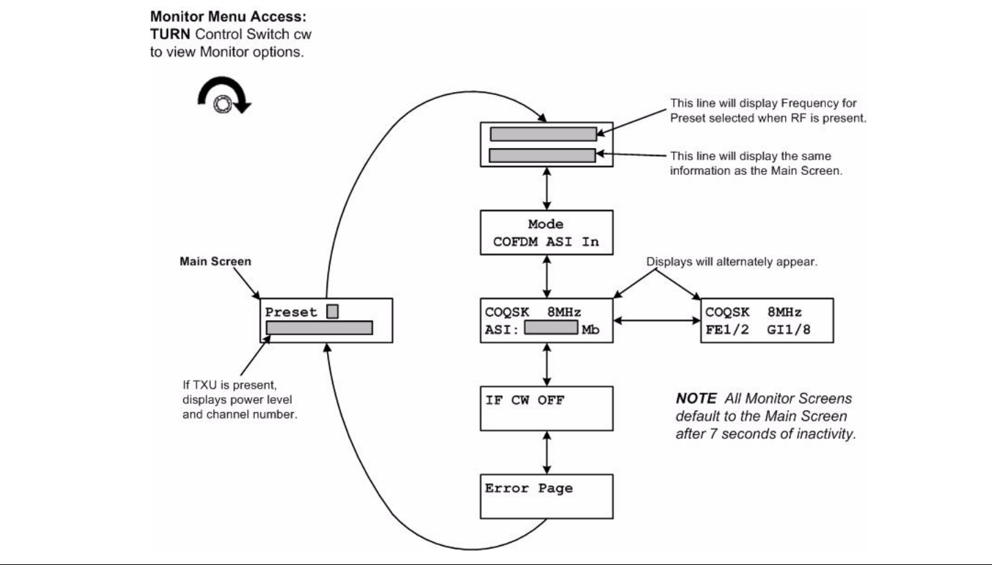
Routine Operation 3-25STRATA TX Operator’s Guide/Tech Ref Manual Routine Operation 3-25STRATA TX Operator’s Guide/Tech Ref Manual
3.5.4 Using the Monitor Screens in COFDM ASI
In Mode
When the STRATA TX System is operating in the COFDM ASI In
mode, the internal MPEG encoder is bypassed and an externally
supplied ASI stream is routed to the monitor and output
connectors and then to the TXU, if present.
See Figure 3-21 for the COFDM ASI In Menu Map.
Figure 3-21: COFDM ASI In Monitor Map
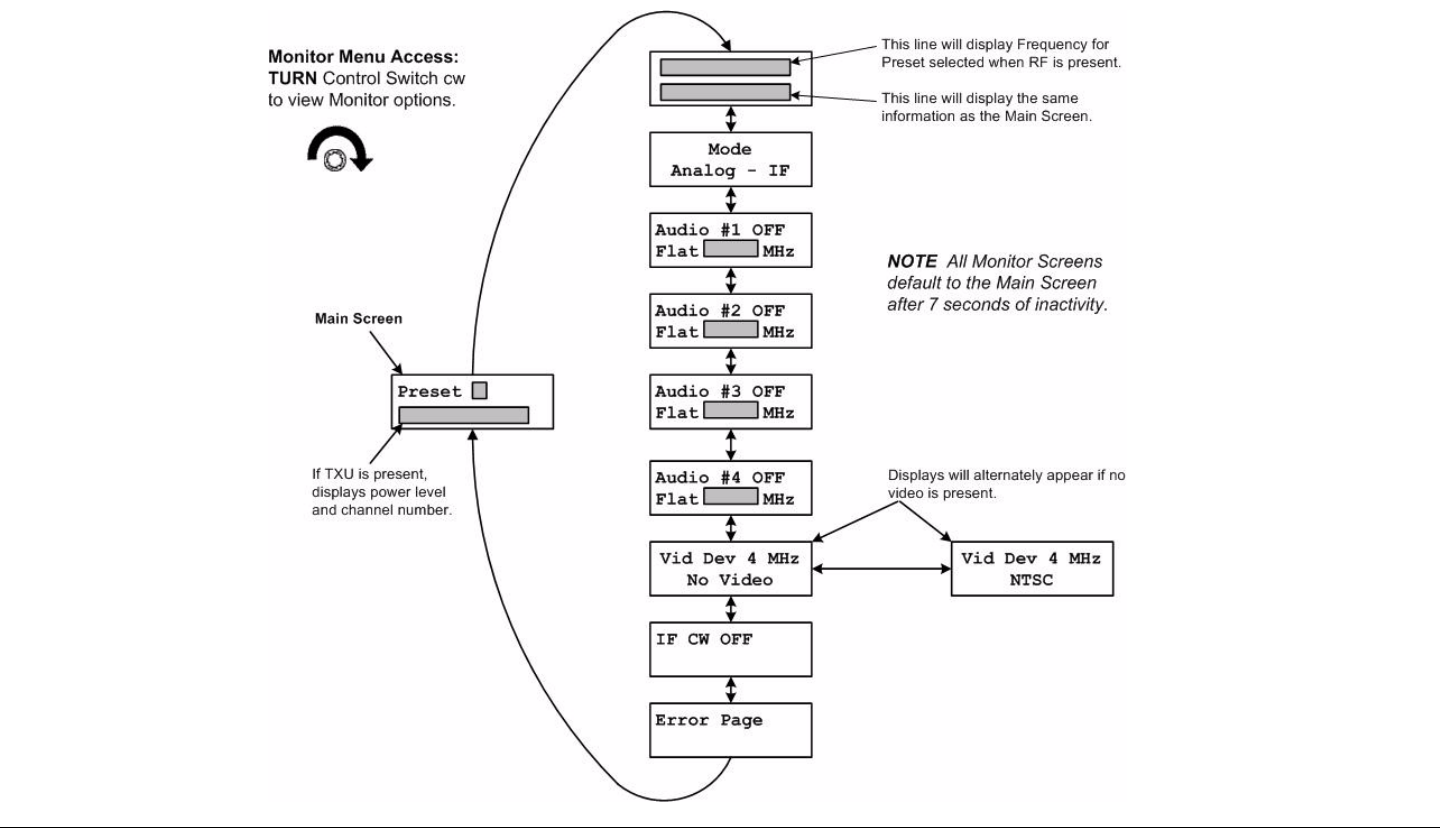
Routine Operation 3-26STRATA TX Operator’s Guide/Tech Ref Manual Routine Operation 3-26STRATA TX Operator’s Guide/Tech Ref Manual
3.5.5 Using the Monitor Screens in Analog - IF
Mode
When the STRATA TX System is operating in the Analog - IF
mode, 70 MHz FM output is routed to the TXU, if present. This
option is only available if the FMT option is installed.
See Figure 3-22 for the Analog - IF Monitor Menu Map.
Figure 3-22: Analog - IF Monitor Menu Map
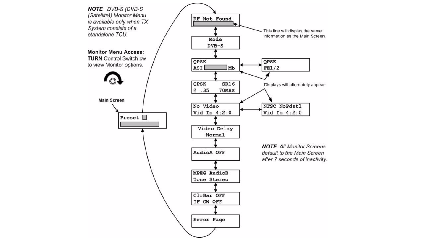
Routine Operation 3-27STRATA TX Operator’s Guide/Tech Ref Manual Routine Operation 3-27STRATA TX Operator’s Guide/Tech Ref Manual
3.5.6 Using the Monitor Screens in DVB-S Mode
When the STRATA TX System is operating in the DVB-S mode,
this mode utilizes a single carrier modulator and supplies a
configurable DVB-S signal to the TCU signal output and monitor
connectors. This mode is operational for QPSK, 16 QAM, and 8
PSK modulation formats. This mode is used for standalone TCU
operations only.
See Figure 3-23 for the DVB-S Monitor Menu Map.
Figure 3-23: DVB-S Monitor Menu Map

Routine Operation 3-28STRATA TX Operator’s Guide/Tech Ref Manual
3.6 TXU and/or TCU Control
Operations
This section describes how to configure your STRATA TX
System using the front panel control switch. Turning the front
panel control switch counterclockwise on either the TXU or TCU
controls transmitter functions including changing Presets,
changing RF channel assignments, setting RF attenuation
levels, and activation of DC power from a TCU to a separately
located TXU, or from a TXU to a separately located TCU.
Settings may be changed on a standalone TCU, a standalone
TXU, or a TXU and TCU TX System.
For a summary of settings that can be changed using the front
panel control switch and which are made using the STRATA TX
Configuration Utility software, see “Front Panel vs. STRATA TX
Configurator Settings” on page 3-35.
Here are the tasks described:
Refer to Figure 3-24 on page 3-29 for the Control Menu Map.
Topic Page
Changing a Preset 3-30
Setting a Channel 3-31
Setting Power Output 3-32
Controlling TCU to TXU
DC Power on Coax
3-33
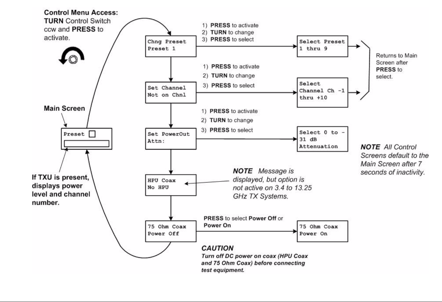
Routine Operation 3-29STRATA TX Operator’s Guide/Tech Ref Manual
Figure 3-24: Control Menu Map Changing a Preset

Routine Operation 3-30STRATA TX Operator’s Guide/Tech Ref Manual
3.6.1 Changing a Preset
The STRATA TX is designed to enable you to control operating
settings through Presets stored in the transmitter. The STRATA
TCU and TXU are shipped with factory Presets and can be
customized for the user.
Your STRATA TX System can be pre-configured with up to 9
Presets. Each Preset contains most of the operating settings
needed to control the STRATA TX System. System Presets can
only be defined and changed using the STRATA TX
Configuration Utility software. Presets cannot be changed from
the TXU or TCU front panels.
For information on configuring Presets, see the “Configurator
Reference” Appendix on page C-1 (part of the STRATA TX
Technical Reference Manual only).
Notes When you change a Preset, the new Preset
remains in effect. When the TX System is powered
down, that Preset is active when the TX System is
powered up again.
When a Preset is changed, the channel does not
change.
When a channel is changed, the Preset does not
change.
To change Presets, perform the following steps:
1. Verify the STRATA TX System is connected and
powered up. See ”Powering the STRATA TX System”
on page 3-12.
2. Observe the Main Screen is displayed. See Figure 3-
25.
Figure 3-25: Main Screen - Changing a Preset
3. Turn the control switch ccw until the display reads
Chng Preset.
Note Changing Presets when the TX System is in the
transmit mode will place the transmitter in the
standby mode when the control switch is pressed.
4. Press the control switch to select Chng Preset. See
Figure 3-26.
Figure 3-26: Change Preset Screen (Typical)
5. Observe the current Preset setting begins to blink.
6. Turn the control switch cw or ccw until the desired
Preset is displayed.
7. Press the control switch once to select that Preset.
8. Observe display changes back to the Main Screen
after a short delay.
9. Observe newly selected Preset is displayed on Main
screen. See Figure 3-27 on page 3-31.
Preset 3
. W
Chng Preset
Preset 1
Blinking

Routine Operation 3-31STRATA TX Operator’s Guide/Tech Ref Manual
Figure 3-27: Main Screen (Typical) - Preset Changed
10. Press the control switch for one second to place the
TX System in the transmit mode, as required.
3.6.2 Setting a Channel
The STRATA TX channel and offset, other than the Preset
channel pre-programmed using the STRATA TX Configuration
Utility software, can be selected from the TXU or TCU front panel
and can be configured for operation on any of up to 10 channels,
with (+) and (-) offsets. For more information, see the “Channels
& Frequencies” Appendix on page A-1.
The frequencies assigned to each channel must be configured
using the STRATA TX Configuration Utility software. The
frequencies cannot be changed from either the TXU or TCU front
panels.
For information on configuring channels, see the “Configurator
Reference” Appendix on page C-1 (part of the STRATA TX
System Technical Reference Manual only).
Preset
. W
New
Preset
Notes The Preset will retain the new channel until the TX
System is powered off. When the TX System is
powered up again, the new channel setting will be
retained.
When a Preset is changed, the channel does not
change.
When a channel is changed, the Preset does not
change.
To select which channel to modify, perform the following steps:
1. Verify the STRATA TX System is connected and
powered up. See ”Powering the STRATA TX System”
on page 3-12.
2. Observe the Main screen is displayed. See Figure 3-
28.
Figure 3-28: Main Screen
3. Turn the control switch ccw until the display reads Set
Channel. See Figure 3-29.
Figure 3-29: Change a Channel (Typical)
Preset 3
. W
Set Channel
Not On Chnl

Routine Operation 3-32STRATA TX Operator’s Guide/Tech Ref Manual
Note Changing Channels when the TX System is in the
transmit mode will place the transmitter in the
standby mode when the control switch is pressed.
4. Press the control switch once to select Set Channel
and observe the channel selected begins to blink.
5. Turn the control switch cw or ccw until the desired
channel and offset are displayed.
6. Press the control switch once to select that channel
and offset.
7. Observe the display changes back to the Main screen
after a short delay.
8. Press the control switch for one second to place the
TX System in the transmit mode, as required.
3.6.3 Setting Power Output
The power output of your STRATA TX System can be set by
controlling the attenuation, in dB, from either the TXU or TCU
front panel.
Note Maximum power output occurs with 0 dB of
attenuation selected. Attenuation levels from 0 dB
to -31 dB may be selected in 1 dB increments.
To select power output attenuation, perform the following steps:
1. Verify the STRATA TX System is connected and
powered up. See ”Powering the STRATA TX System”
on page 3-12.
2. Observe the Main screen is displayed. See Figure 3-
30.
Figure 3-30: Main Screen (Typical) - Power Output
3. Turn the control switch ccw until the display reads
Set PowerOut. See Figure 3-31.
Figure 3-31: Change Power Output (Typical)
Notes Changing power output attenuation when the TX
System is in the transmit mode will place the
transmitter in the standby mode when the control
switch is pressed.
Output power attenuation level must be reset or
verified whenever Presets are changed .
4. Press the control switch once and observe the ATTN:
dB line begins to blink.
5. Turn the control switch cw or ccw until the desired
attenuation level is displayed.
6. Press the control switch to select the power output
attenuation level.
7. Observe the new attenuation level is displayed.
8. After a short delay, observe the Main screen is
displayed.
Preset 3
. W
Set PowerOut
Attn: dB

Routine Operation 3-33STRATA TX Operator’s Guide/Tech Ref Manual
9. Press the control switch for one second to place the
TX System in the transmit mode, as required.
3.6.4 Controlling TCU to TXU DC Power on Coax
If your STRATA TX System requires the TXU and TCU to be
mounted in separate locations, MRC recommends powering the
TCU via the coaxial cable from the TXU.
Note When the TCU and TXU are mounted in separate
locations, it is recommended that DC input power
be connected to the TXU.
Since either unit may be powered from the other
unit via DC power superimposed on the coaxial
cable between the units, DC input power may
therefore be applied to either the TXU or the TCU.
If your TXU and TCU configurations contain DC ON COAX
switches mounted on the units, these switches must be set to
ON in addition to controlling DC power superimposed on the
coaxial cable from the TXU to the TCU or from the TCU to the
TXU.
To apply DC power from the TXU to the TCU superimposed on
the coaxial cable between the two units, perform the following
steps.
Notes This procedure must only be performed on
STRATA TX Systems where the TXU and TCU are
physically mounted in separate locations.
This procedure may be performed using either the
TXU or TCU control switch and display.
Apply DC Power on Coax
1. Verify the STRATA TX System is connected and
powered up. See ”Powering the STRATA TX System”
on page 3-12.
2. Observe the Main screen is displayed. See Figure 3-
32.
Figure 3-32: Main Screen
Note If your TCU does not contain a DC ON COAX
switch, go to step 4.
3. Turn the recessed DC ON COAX switch on the front
panel of the TCU until the screw slot points to OFF.
4. Turn the recessed DC ON COAX switch on the front
panel of the TXU until the screw slot points to OFF.
5. Turn the control switch ccw until the display reads 75
Ohm Coax. See Figure 3-33.
Preset 3
. W

Routine Operation 3-34STRATA TX Operator’s Guide/Tech Ref Manual
Figure 3-33: 75 Ohm Coax
Note Pressing the control switch to select application of
DC power on the coaxial cable from the TXU to the
TCU or from the TCU to the TXU when the TX
System is in the transmit mode will place the
transmitter in the standby mode.
6. Press the control switch one time to change Power
Off to Power On.
7. After a short delay, observe the Main screen is
displayed.
8. Press the control switch for one second to place the
TX System in the transmit mode, as required.
Remove DC Power on Coax
Note This procedure may be performed using either the
TXU or TCU control switch and display.
1. Observe the Main Screen is displayed.
2. Turn the control switch ccw until the display reads 75
Ohm Coax.
3. Press the control switch one time to change the
display from Power On to Power Off.
4. After a short delay, observe the Main screen is
displayed.
75 Ohm Coax
Power Off
Note If your TCU does not contain a DC ON COAX
switch, go to step 6.
5. Turn the recessed DC ON COAX switch on the front
panel of the TCU until the screw slot points to ON.
6. Turn the recessed DC ON COAX switch on the front
panel of the TXU until the screw slot points to ON.
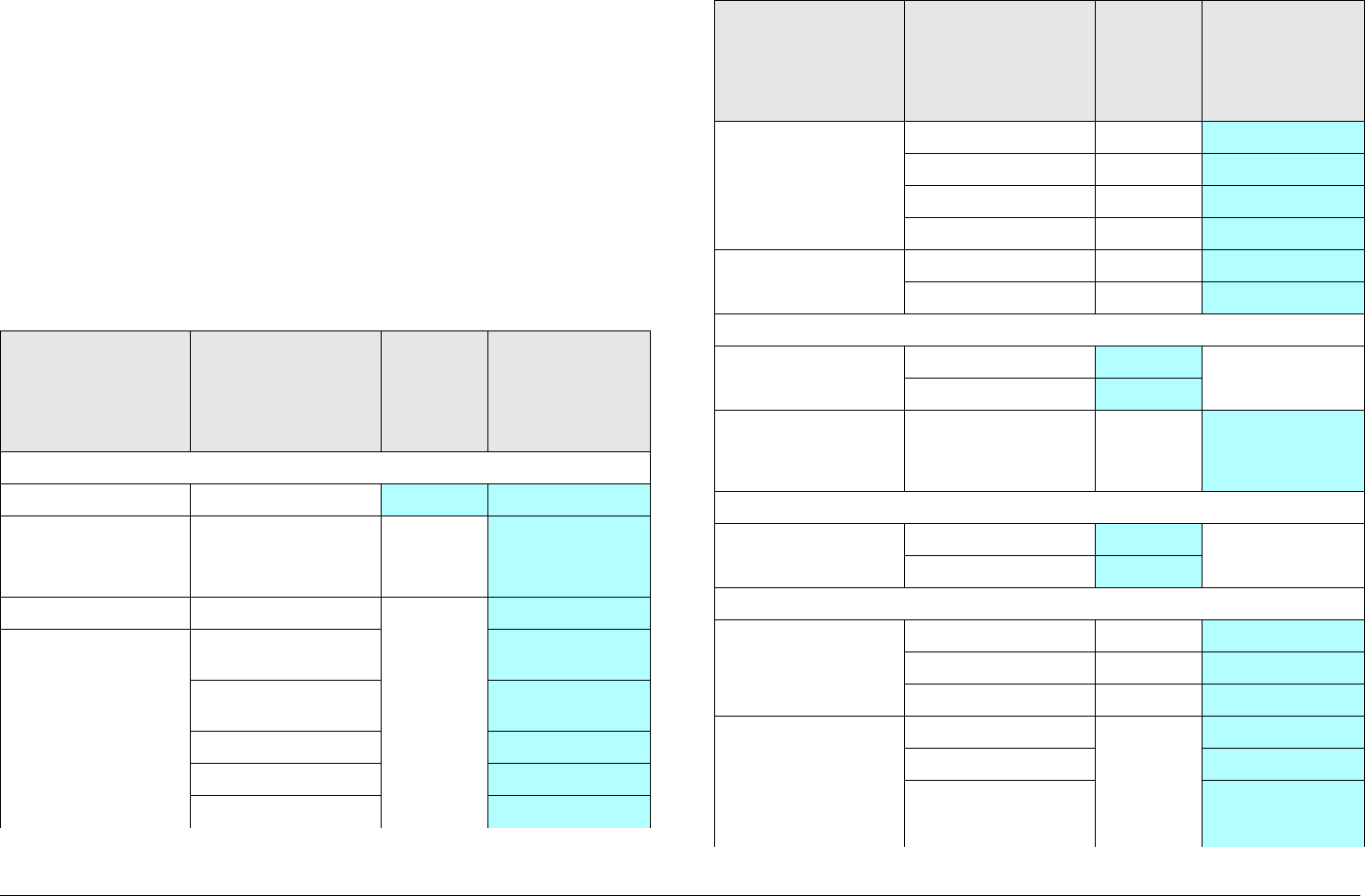
Routine Operation 3-35STRATA TX Operator’s Guide/Tech Ref Manual
3.7 Front Panel vs. STRATA TX
Configurator Settings
The design of the STRATA TX System and STRATA TX
Configuration Utility software makes commonly available
settings accessible from the TXU and/or TCU front panel and
more advanced settings accessible through the STRATA TX
Configuration Utility.
A summary of settings that can be controlled by each method is
shown in Table 3-1.
Table 3-1: Front Panel vs. Configurator Settings
Parameter Available
Settings
Set
Using
Control
Switch
Set Using TX
Configurator
Presets
Preset in use 1, 2,... 9 ✔ ✔
Preset text Any 12
alphanumeric
characters
✔
Operation Mode • MPEG IF Out ✔
• MPEG ASI
Out
✔
• COFDM-ASI
In
✔
• Ext IF In ✔
• Analog IF Out ✔
• DVB-Satellite ✔
Color Bars • PAL ✔
•NTSC ✔
•OFF ✔
•Auto ✔
IF CW Tone • ON ✔
•OFF ✔
Channels
Channel &
Offset in use
• 1 thru 10 ✔
• -, Center, + ✔
Channel &
Offset
frequencies
Depends on band ✔
DC Power
DC On Coax (75
Ohm Coax)
• Power Off ✔
• Power On ✔
COFDM
COFDM
Bandwidth
•6 MHz ✔
•7 MHz ✔
•8 MHz ✔
COFDM
Modulation
(MPEG IF Out
and COFDM-
ASI In Modes)
• QSPK ✔
• 16 QAM ✔
• 64 QAM ✔
Table 3-1: Front Panel vs. Configurator Settings (Continued)
Parameter Available
Settings
Set
Using
Control
Switch
Set Using TX
Configurator
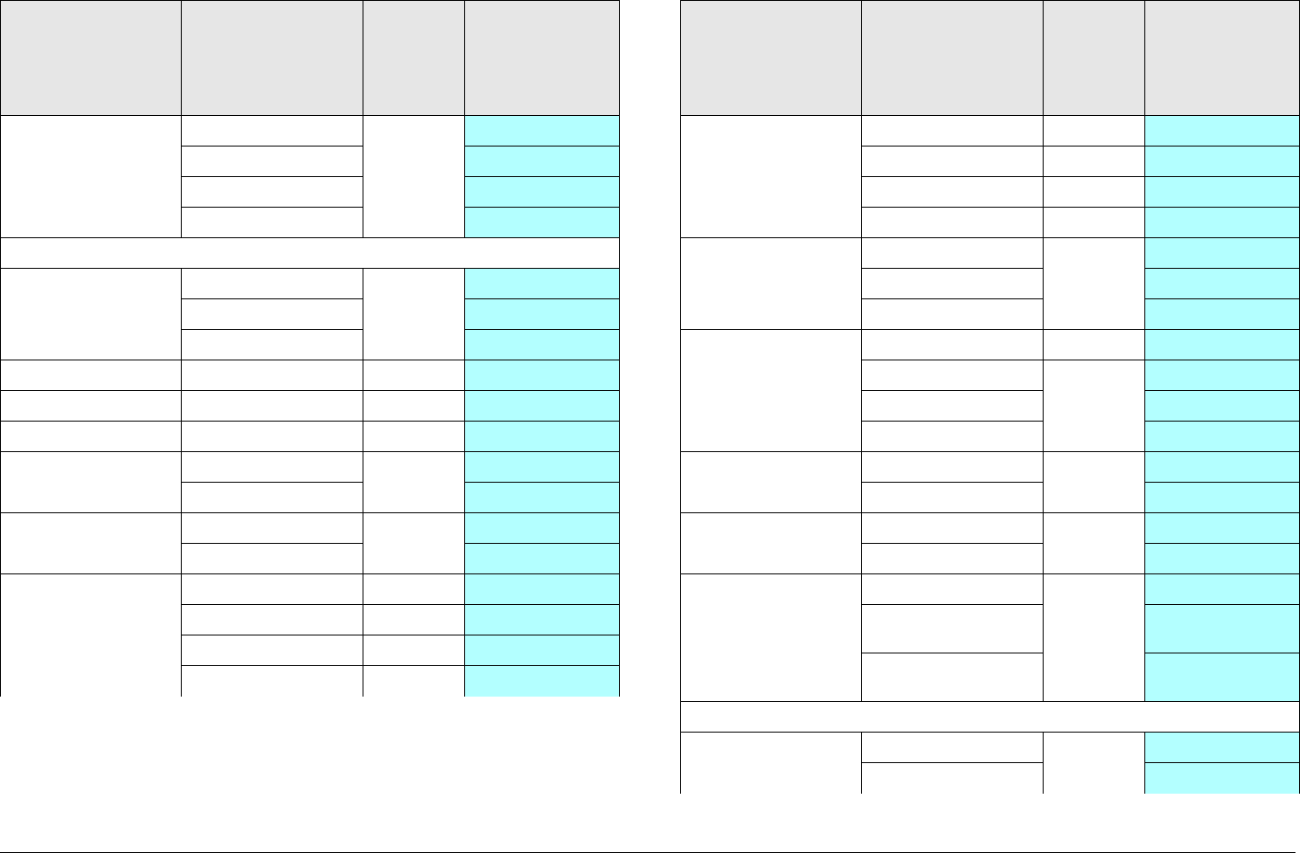
Routine Operation 3-36STRATA TX Operator’s Guide/Tech Ref Manual
COFDM Guard
Interval
•1/32 ✔
•1/16 ✔
•1/8 ✔
•1/4 ✔
MPEG
Audio A Type • OFF ✔
• MPEG ✔
• Linear ✔
Audio B Type • OFF ✔
• MPEG ✔
• Linear ✔
Audio A Mode • Stereo ✔
• Dual Mono ✔
Audio B Mode • Stereo ✔
• Dual Mono ✔
Audio A Input • Test Tone ✔
• Analog ✔
• SDI EMB ✔
• AES EBU ✔
Table 3-1: Front Panel vs. Configurator Settings (Continued)
Parameter Available
Settings
Set
Using
Control
Switch
Set Using TX
Configurator
Audio B Input • Test Tone ✔
• Analog ✔
• SDI EMB ✔
• AES EBU ✔
BISS • OFF ✔
•BISS-1 ✔
•BISS-E ✔
Video Input • SDI 625 In ✔
•PAL In ✔
• PAL M In ✔
• PAL N In ✔
Chroma Format • 4:2:0 ✔
•4:2:2 ✔
Delay Mode • Standard ✔
• Low ✔
Wayside
Channel State
•OFF ✔
•IRD
Compatible
✔
•STRATA
Compatible
✔
FMT
Video Deviation • 3 MHz ✔
•4 MHz ✔
Table 3-1: Front Panel vs. Configurator Settings (Continued)
Parameter Available
Settings
Set
Using
Control
Switch
Set Using TX
Configurator
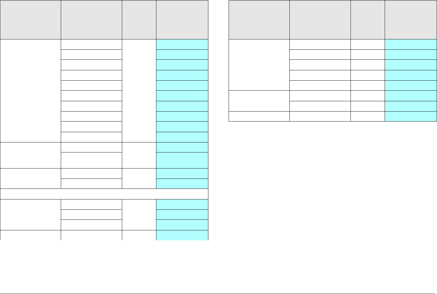
Routine Operation 3-37STRATA TX Operator’s Guide/Tech Ref Manual
Audio Channel 1
thru 4
Frequency
• 4830 kHz ✔
• 5200 kHz ✔
• 5800 kHz ✔
• 6200 kHz ✔
• 6800 kHz ✔
• 7020 kHz ✔
• 7500 kHz ✔
• 8065 kHz ✔
• 8300 kHz ✔
• 8590 kHz ✔
Audio Channel
Frequency
Enabled
• Selected ✔
• Not selected ✔
Pre-emphasis • Selected ✔
• Not selected ✔
DVB-Satellite
Modulation • QSPK ✔
• 16 QAM ✔
• 8 PSK ✔
Symbol Rate • (Variable) ✔
Table 3-1: Front Panel vs. Configurator Settings (Continued)
Parameter Available
Settings
Set
Using
Control
Switch
Set Using TX
Configurator
Forward Error
Correction
•1/2 ✔
•2/3 ✔
•3/4 ✔
•5/6 ✔
•7/8 ✔
Roll Off Factor • 0.25 ✔
•0.35 ✔
IF Frequency • (Variable) ✔
Table 3-1: Front Panel vs. Configurator Settings (Continued)
Parameter Available
Settings
Set
Using
Control
Switch
Set Using TX
Configurator

Routine Operation 3-38STRATA TX Operator’s Guide/Tech Ref Manual
This page intentionally left blank.
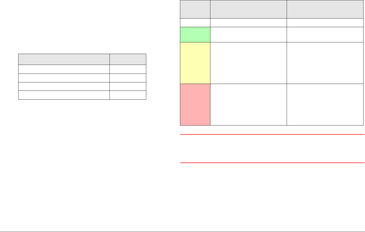
4
Troubleshooting 4-1STRATA TX Operator’s Guide/Tech Ref Manual
Troubleshooting
4.1 Chapter Overview
This chapter describes how to troubleshoot your STRATA TX
System.
Here are the topics covered:
4.2 Status LED
Above the PWR switch on both the TXU and TCU is a multi-
color Status LED. The LED indications are listed in Table 4-1.
Topic Page
Status LED 4-1
Messages on Display 4-1
Error Codes 4-3
Operational Problems 4-8
WARNING A Major Alarm may also indicate a potential
safety hazard. Shut down the STRATA TX
System and disconnect power.
4.3 Messages on Display
One of the ways the STRATA TX System will alert you to problems is
by error messages on the TXU and/or TCU front panel displays.
These are displayed on the Monitor Screens.
See Table 4-2 on page 4-2 for descriptions of the messages and
what to do when they appear.
Table 4-1: Status LED Indications
LED
Color Meaning Suggested Action
----- Power is not on in that unit. Turn on power, as required.
Green Power is on and no errors
are detected.
None.
Amber Minor Alarm - Power is on
but some part of the system
reports an abnormal
condition that requires
attention. Condition might
impair performance.
Check Monitor Screens for
error messages or Error
Codes. Troubleshoot using
tables in this chapter.
Red Major Alarm - Power is on
but there is a serious failure
or error that will prevent
normal operation. The
internal processors are not
running.
Turn off unit and
disconnect power.

Troubleshooting 4-2STRATA TX Operator’s Guide/Tech Ref Manual
Table 4-2: Display Messages
Message Meaning Suggested Operator Action Suggested Technical Staff Action
Not On Chnl Channel frequencies
defined in the Channel
Plan for that band are not
being recognized.
Contact technical staff. • Use STRATA TX Configuration Utility to
check settings. Check the Channel
Plan to be sure it is correct. Verify
Channel Plan matches the transmitter
settings.
• If message persists even when
operating on a frequency that matches
the channel plan, unit may have
suffered internal failure. Call MRC
Technical Support.
No Video The TX is unable to lock on
video signal.
• Check cable connection between
antenna and TX System.
• Check cable connection between TXU
and TCU.
• Contact technical staff.
• Use STRATA TX Configuration Utility to
check settings.
• If message persists, unit may have
suffered internal failure. Call MRC
Technical Support.

Troubleshooting 4-3STRATA TX Operator’s Guide/Tech Ref Manual
4.4 Error Codes
The STRATA TX has an extensive library of diagnostic Error
Codes to help you pinpoint any problems.
These Error Codes:
• Are displayed on the front panel display, on the Error
Code Screen.
• Cause the Status LED to glow amber, alerting you to
investigate the problem.
The Error Codes are formatted into 2 groups of characters, as
described in Figure 4-1.
4.4.1 Primary Error Code
The first group of characters is the Primary Error Code. In most
cases this portion of the Error Code will uniquely identify the
problem.
See Table 4-3 on page 4-4 for descriptions of the error codes
and what to do when they appear.
Figure 4-1: Error Code Format
E141 41
Primary Error Code
Identifies error condition.
See Section 4.4.1 .
Unit ID
Identifies unit
reporting error.
See Section 4.4.3
on page 4-8.
Error Status
Depends on
error code.
See Section 4.4.2
on page 4-8.

Troubleshooting 4-4STRATA TX Operator’s Guide/Tech Ref Manual
Table 4-3: Primary Error Codes
Error Code Meaning Suggested Operator Action Suggested Technical Staff Action
Status Errors
(Some part of System is reporting an abnormal condition.)
E020 TXU IF Fault • Verify condition of all cable
connections.
• Contact technical staff.
Call MRC Technical Support.
E021 TXU RF Fault • Verify condition of all cable
connections.
• Contact technical staff.
Call MRC Technical Support.
E0E0 FMT Video PLL Unlocked Note - This error will appear only if the TX
System contains the FMT option.
• Contact technical staff.
• Verify video input is at the correct
level.
• Call MRC Technical Support.
E0E1 FMT Audio 1 PLL Unlocked Note - These errors will appear only if the
TX System contains the FMT option.
• Check FMT settings using Monitor
Screens and Command Screens.
Settings must match transmitter
settings.
• Contact technical staff.
• Use STRATA TX Configuration Utility
to check FMT settings. Be sure all
settings match the transmitter
settings.
• Use STRATA TX Configuration Utility
to reprogram all the settings in the
radio.
• If problem persists, possible
hardware failure. Call MRC Technical
Support.
E0E2 FMT Audio 2 PLL Unlocked
E0E3 FMT Audio 3 PLL Unlocked
E0E4 FMT Audio 4 PLL Unlocked

Troubleshooting 4-5STRATA TX Operator’s Guide/Tech Ref Manual
E080 Communication Failure with the
COFDM/MPEG Unit
Note - This error will appear only if the TX
System contains the COFDM/MPEG
option.
• If the TX System contains a
standalone TXU or TCU, contact
technical staff.
• If the TX System contains both a TXU
and a TCU, verify condition of cable
connections. Contact technical staff.
If problem persists, possible hardware
failure. Call MRC Technical Support.
Parameter Errors
(Some internal parameter is outside of allowable limits.)
E030 TXU 2.048 Volt Reference Error • Check for Error Codes related to
power - E035 thru E039 and E03A
thru E03E. Correct power problem.
• Contact technical staff.
If errors persist with correct power
connected, unit has suffered internal
failure. Call MRC Technical Support.
E031 TXU 5.5 Volt Reference Error
E032 TXU 7 Volt Line Error
E033 TXU 11 Volt Line Error
E034 TXU Temperature Error Note - TXU internal fans operate only
when TX System is transmitting. Fan
operation can be determined by listening
for audible fan noise or by feeling for
airflow at rear of TXU when TX System is
in transmit mode.
• Verify TXU internal fans are operating
when TX System is transmitting.
• Check TXU to be sure it is not too
close to sources of heat. Relocate
TXU, if possible.
• Verify TXU has room around it for air
circulation. Move objects preventing
air flow.
• Contact technical staff.
If errors persist with proper location and
airflow and correct power is connected,
unit has suffered internal failure. Call
MRC Technical Support.
Table 4-3: Primary Error Codes (Continued)
Error Code Meaning Suggested Operator Action Suggested Technical Staff Action

Troubleshooting 4-6STRATA TX Operator’s Guide/Tech Ref Manual
E035 TXU 75 Ohm Coax Current Error Note - these errors can only appear in a
TX System with TXU and a TCU, when
powering the TXU from the TCU or from
the TCU to the TXU via DC power
superimposed on the coax cable
between the TCU and the TXU.
• Check connection of coax cable
between TCU and TXU. Verify
connectors are fully mated and verify
cable and connectors are
undamaged.
• Make sure all power cables are
connected properly.
• Contact technical staff.
If errors persist with correct coax
connections and correct power
connected, unit has suffered internal
failure. Call MRC Technical Support.
E036 TXU 75 Ohm Coax Voltage error
E037 TXU 75 Ohm Coax Power Error
E038 TXU 50 Ohm Coax Current Error
E039 TXU 50 Ohm Coax Voltage error
E03A TXU 50 Ohm Coax Power Error
E03B TXU Circular Connector Current
Error
• Verify all power cables are properly
connected and are not damaged.
• Verify correct DC input power is being
applied to the TXU.
• Contact technical staff.
If errors persist with correct power
connected, unit has suffered internal
failure. Call MRC Technical Support.
E03C TXU Circular Connector Voltage
Error
E03D TXU Circular Connector Power
Error
E03E TXU DC Bus Error • Contact technical staff. Call MRC Technical Support.
E040 TCU 2.048 Volt Reference Error • Check for error codes related to
power - E043 thru E048. Correct
power problem
• Contact technical staff.
If errors persist with correct power
connected, unit has suffered internal
failure. Call MRC Technical Support.
E041 TCU 5.5 Volt Reference Error
Table 4-3: Primary Error Codes (Continued)
Error Code Meaning Suggested Operator Action Suggested Technical Staff Action

Troubleshooting 4-7STRATA TX Operator’s Guide/Tech Ref Manual
E042 TCU Temperature error • Check TCU to be sure it is not too
close to sources of heat. Relocate
TCU, if possible.
• Verify TCU has room around it for air
circulation. Move objects preventing
air flow.
• Contact technical staff.
If errors persist with proper location and
airflow and correct power is connected,
unit has suffered internal failure. Call
MRC Technical Support.
E043 TCU 75 Ohm Coax Current Error Note - these errors can only appear in a
TX System with TXU and a TCU, when
powering the TXU from the TCU or from
the TCU to the TXU via DC power
superimposed on the coax cable
between the TCU and the TXU.
• Check connection of coax cable
between TCU and TXU. Verify
connectors are fully mated and verify
cable and connectors are
undamaged.
• Make sure all power cables are
connected properly.
• Contact technical staff.
If errors persist with correct coax
connections and correct power
connected, unit has suffered internal
failure. Call MRC Technical Support.
E044 TCU 75 Ohm Coax Voltage Error
E045 TCU 75 Ohm Coax Power Error
E046 TCU Circular Connector Current
Error
• Make sure all power cables are
connected properly and are not
damaged.
• Verify correct DC input power is being
applied to the TCU.
• Contact technical staff.
If errors persist with correct power
connected, unit has suffered internal
failure. Call MRC Technical Support.
E047 TCU Circular Connector Voltage
Error
E048 TCU Circular Connector Power
Error
E049 TCU DC Bus Error Contact technical staff. Call MRC Technical Support.
Table 4-3: Primary Error Codes (Continued)
Error Code Meaning Suggested Operator Action Suggested Technical Staff Action

Troubleshooting 4-8STRATA TX Operator’s Guide/Tech Ref Manual
4.4.2 Error Status
The significance of the Error Status digit depends on what
Primary Error Code is being reported. See Table 4-4.
4.4.3 Unit ID
The Unit ID digit identifies which part of the STRATA TX System
is reporting a problem. See Table 4-5.
Table 4-4: Error Status Digit
Status Digit Meaning
Status Error (Error Codes E0E0 thru E0E4, E020,
E021, and E080)
8 There is an error.
Parameter Error (Error Codes E030 thru E039, E03A
thru E03E, and E042 thru E049, E060 thru E069, and
E06A)
4 Value is too low.
8 Value is too high.
Table 4-5: STRATA Unit ID Digit
Unit ID
1 Transmitter Unit (TXU)
2 Transmitter Control Unit (TCU)
4.5 Operational Problems
Information provided on the following pages will assist you in
troubleshooting problems that arise in the operation of your
STRATA TX System.
For video problems, See Table 4-6 on page 4-9; for general
system problems, See Table 4-7 on page 4-10.

Troubleshooting 4-9STRATA TX Operator’s Guide/Tech Ref Manual
Table 4-6: Video Problems
Problem Possible Cause Suggested Operator Action Suggested Technical Staff Action
Video Problems
No video. Problem with video source
or cabling
• Check video source and
cabling.
• Contact technical staff.
• Check video source and cabling.
• Call MRC Technical Support.
Transmitter and Receiver
compatibility problems
• Verify Transmitter and
Receiver are both operating in
the same digital or analog
modes.
• Verify Transmitter and
Receiver are both operating on
the same frequency. If
frequency offsets are used,
verify offsets are identical
between Transmitter and
Receiver.
• Contact technical staff.
• Call MRC Technical Support
Video source configuration
problem
• Verify TXU/TCU front panel
settings match video source
inputs.
• Contact technical staff.
• Verify video inputs match STRATA TX
Configuration Utility settings.
• Call MRC Technical Support.

Troubleshooting 4-10STRATA TX Operator’s Guide/Tech Ref Manual
Table 4-7: General System Problems
Problem Possible Cause Suggested Operator Action Suggested Technical Staff Action
General System Problems
Status LED on TXU/
TCU is yellow.
TX System is indicating a
Minor Alarm.
• Check all Monitor Screens on
TXU/TCU display.
Troubleshoot per Section 4.3
on page 4-1.
• Check Error Code Screen on
TXU/TCU display.
Troubleshoot per Section 4.4
on page 4-3.
• Error messages: Troubleshoot per
Section 4.3 on page 4-1.
• Error Codes: Troubleshoot per Section 4.4 on
page 4-3.
Status LED on TXU or
TCU is red.
TX is indicating a Major
Alarm.
TURN OFF POWER and call for
service.
Call MRC Technical Support.
Changing settings on
one unit doesn’t
change settings on the
other in a connected
TXU and TCU system.
TXU and TCU are not
communicating.
• Check connection between
TXU and TCU.
• Turn power off in both TXU
and TCU. Then turn power on
in both TXU and TCU.
If problem persists with correct coax connections,
one or both units have suffered internal failure.
Call MRC Technical Support.
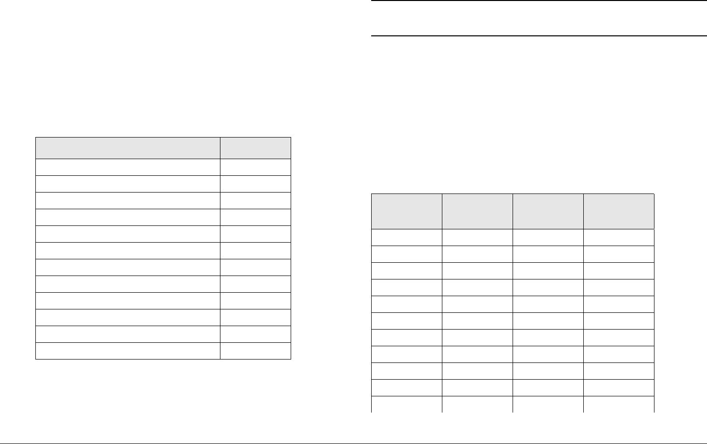
A
Channels & Frequencies A-1STRATA TX Operator’s Guide/Tech Ref Manual
Channels &
Frequencies
A.1 Appendix Overview
This Appendix presents the channels and frequencies that can
be programmed into your STRATA TX System at the factory.
Here are the topics covered:
A.2 Initial Factory Presets
This section lists the channels and frequencies for each RF band
covered by the STRATA TX System. These frequencies are
Topic Page
Initial Factory Presets A-1
3.4 to 3.8 GHz Channel Plan A-1
4.4 to 5.0 GHz Channel Plan A-2
6.4 to 7.1 GHz Channel Plan A-2
6.9 to 7.5 GHz Channel Plan A-3
7.4 to 8.0 GHz Channel Plan A-3
7.8 to 8.5 GHz Channel Plan A-4
8.2 to 8.9 GHz Channel Plan A-4
10.0 to 10.7 GHz Channel Plan A-5
10.5 to 11.2 GHz Channel Plan A-5
10.8 to 11.5 GHz Channel Plan A-6
12.7 to 13.25 GHz Channel Plan A-6
preset at the factory, but can be modified using the STRATA TX
Configurator software.
Note These frequency settings should only be changed
by qualified technical personnel.
Contact the Society of Broadcast Engineers (SBE) coordinator
for up-to-date information on local frequency plans for Electronic
News Gathering (ENG) and Remote Pickup (RPU) operations.
A.2.1 3.4 to 3.8 GHz Channel Plan
The channel plan for the 3.4 to 3.8 GHz STRATA TX System is
contained in Tab le A - 1.
Table A-1: 3.4 to 3.8 GHz Channel Plan
Channel (-) Offset
(MHz)
(0) Center
(MHz)
(+) Offset
(MHz)
1 3406.250 3418.250 3431.250
2 3443.250 3455.250 3467.250
3 3480.250 3492.250 3504.250
4 3506.250 3518.750 3531.250
5 3543.750 3556.250 3568.750
6 3581.250 3593.750 3606.250
7 3610.000 3620.000 3630.000
8 3640.000 3650.000 3660.000
9 3670.000 3680.000 3690.000
10 3700.000 3710.000 3720.000
11 3730.000 3740.000 3750.000
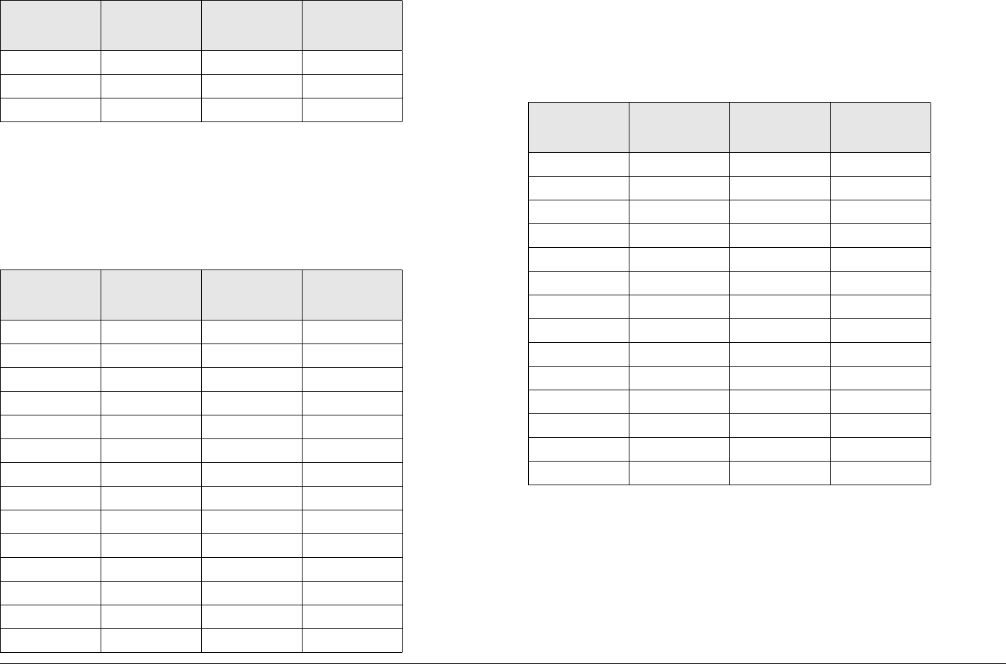
Channels & Frequencies A-2STRATA TX Operator’s Guide/Tech Ref Manual
A.2.2 4.4 to 5.0 GHz Channel Plan
The channel plan for the 4.4 to 5.0 GHz STRATA TX System is
contained in Tab le A- 2.
12 3760.000 3770.000 3780.000
13 3790.000 3800.000 3800.000
14 3800.000 3800.000 3800.000
Table A-2: 4.4 to 5.0 GHz Channel Plan
Channel (-) Offset
(MHz)
(0) Center
(MHz)
(+) Offset
(MHz)
1 4450.000 4475.000 4500.000
2 4525.000 4550.000 4575.000
3 4600.000 4625.000 4650.000
4 4675.000 4700.000 4725.000
5 4750.000 4775.000 4800.000
6 4825.000 4850.000 4875.000
7 4900.000 4925.000 4925.000
8 4940.500 4941.500 4942.500
9 4943.500 4944.500 4944.500
10 4947.500 4952.000 4957.500
11 4962.500 4967.500 4972.500
12 4977.500 4982.500 4982.500
13 4985.500 4986.500 4987.500
14 4988.500 4989.500 4989.500
Table A-1: 3.4 to 3.8 GHz Channel Plan
Channel (-) Offset
(MHz)
(0) Center
(MHz)
(+) Offset
(MHz)
A.2.3 6.4 to 7.1 GHz Channel Plan
The channel plan for the 6.4 to 7.1 GHz STRATA TX System is
contained in Tab le A - 3.
Table A-3: 6.4 to 7.1 GHz Channel Plan
Channel (-) Offset
(MHz)
(0) Center
(MHz)
(+) Offset
(MHz)
1 6881.250 6887.500 6893.750
2 6906.250 6912.500 6918.750
3 6931.250 6937.500 6943.750
4 6956.250 6962.500 6968.750
5 6981.250 6987.500 6993.750
6 7006.250 7012.500 7018.750
7 7031.250 7037.500 7043.750
8 7056.250 7062.500 7068.750
9 7081.250 7087.500 7093.750
10 7106.250 7112.500 7118.750
11 6431.250 6437.500 6443.750
12 6456.250 6462.500 6468.750
13 6481.250 6487.500 6493.750
14 65.6.250 6512.500 6518.750
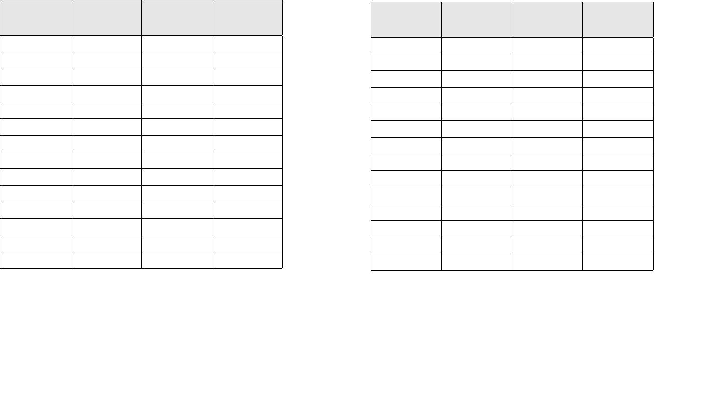
Channels & Frequencies A-3STRATA TX Operator’s Guide/Tech Ref Manual
A.2.4 6.9 to 7.5 GHz Channel Plan
The channel plan for the 6.9 to 7.5 GHz STRATA TX System is
contained in Tab le A- 4.
Table A-4: 6.9 to 7.5 GHz Channel Plan
Channel (-) Offset
(MHz)
(0) Center
(MHz)
(+) Offset
(MHz)
1 6900.000 6915.000 6930.250
2 6945.250 6960.000 6975.750
3 6990.250 7005.000 7020.750
4 7035.250 7050.000 7065.750
5 7080.250 7095.000 7110.750
6 7125.250 7140.000 7155.750
7 7170.250 7185.000 7200.750
8 7215.250 7230.000 7245.750
9 7260.250 7275.000 7290.750
10 7305.250 7320.000 7335.750
11 7350.250 7365.000 7380.750
12 7395.250 7410.000 7425.750
13 7440.250 7455.000 7470.750
14 7485.250 7500.000 7500.000
A.2.5 7.4 to 8.0 GHz Channel Plan
The channel plan for the 7.4 to 8.0 GHz STRATA TX System is
contained in Tab le A - 5.
Table A-5: 7.4 to 8.0 GHz Channel Plan
Channel (-) Offset
(MHz)
(0) Center
(MHz)
(+) Offset
(MHz)
1 7405.000 7425.000 7445.000
2 7455.000 7475.000 7495.000
3 7505.000 7525.000 7545.000
4 7555.000 7575.000 7595.000
5 7605.000 7625.000 7645.000
6 7655.000 7675.000 7695.000
7 7705.000 7725.000 7745.000
8 7755.000 7775.000 7795.000
9 7805.000 7825.000 7845.000
10 7855.000 7875.000 7895.000
11 7905.000 7925.000 7945.000
12 7955.000 7975.000 7995.000
13 8005.000 8025.000 8045.000
14 8055.000 8075.000 7085.000
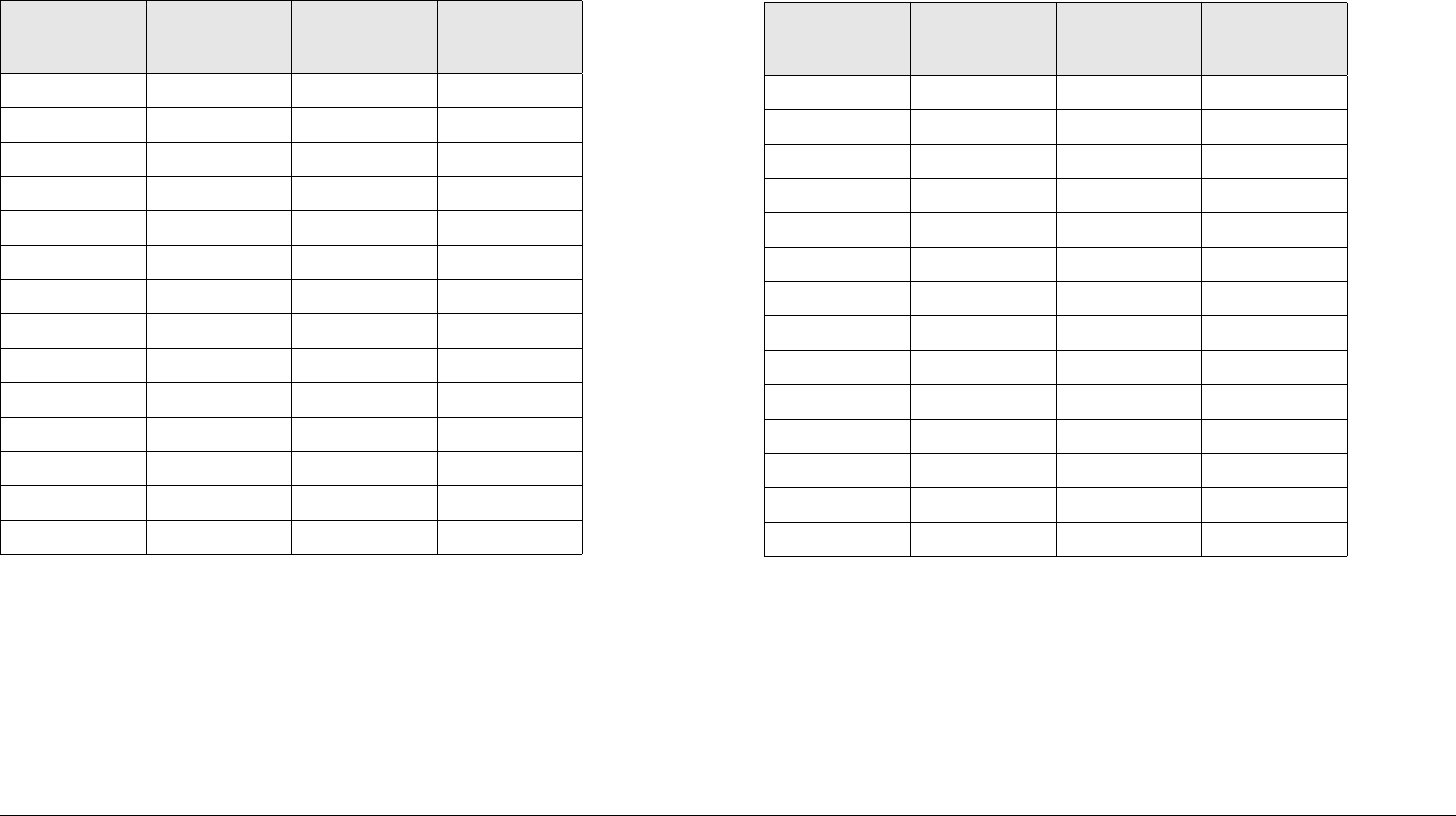
Channels & Frequencies A-4STRATA TX Operator’s Guide/Tech Ref Manual
A.2.6 7.8 to 8.5 GHz Channel Plan
The channel plan for the 7.8 to 8.5 GHz STRATA TX System is
contained in Tab le A- 6.
Table A-6: 7.8 to 8.5 GHz Channel Plan
Channel (-) Offset
(MHz)
(0) Center
(MHz)
(+) Offset
(MHz)
1 7805.000 7825.000 7845.000
2 7855.000 7875.000 7895.000
3 7905.000 7925.000 7945.000
4 7955.000 7975.000 7995.000
5 8005.000 8025.000 8045.000
6 8055.000 8075.000 8095.000
7 8105.000 8125.000 8145.000
8 8155.000 8175.000 8195.000
9 8205.000 8225.000 8245.000
10 8255.000 8275.000 8295.000
11 8305.000 8325.000 8345.000
12 8355.000 8375.000 8395.000
13 8405.000 8425.000 8445.000
14 8455.000 8475.000 8495.000
A.2.7 8.2 to 8.9 GHz Channel Plan
The channel plan for the 8.2 to 8.9 GHz STRATA TX System is
contained in Tab le A - 7.
Table A-7: 8.2 to 8.9 GHz Channel Plan
Channel (-) Offset
(MHz)
(0) Center
(MHz)
(+) Offset
(MHz)
1 8205.000 8225.000 8245.000
2 8255.000 8275.000 8295.000
3 8305.000 8325.000 8345.000
4 8355.000 8375.000 8395.000
5 8405.000 8425.000 8445.000
6 8455.000 8475.000 8495.000
7 8505.000 8525.000 8545.000
8 8555.000 8575.000 8595.000
9 8605.000 8625.000 8645.000
10 8655.000 8675.000 8695.000
11 8705.000 8725.000 8745.000
12 8755.000 8775.000 8795.000
13 8805.000 8825.000 8845.000
14 8855.000 8875.000 8895.000

Channels & Frequencies A-5STRATA TX Operator’s Guide/Tech Ref Manual
A.2.8 10.0 to 10.7 GHz Channel Plan
The channel plan for the 10.0 to 10.7 GHz STRATA TX System
is contained in Table A- 8.
Table A-8: 10.0 to 10.7 GHz Channel Plan
Channel (-) Offset
(MHz)
(0) Center
(MHz)
(+) Offset
(MHz)
1 10005.000 10025.000 10045.000
2 10055.000 10075.000 10095.000
3 10105.000 10125.000 10145.000
4 10155.000 10175.000 10195.000
5 10205.000 10225.000 10245.000
6 10255.000 10275.000 10295.000
7 10305.000 10325.000 10345.000
8 10355.000 10375.000 10395.000
9 10405.000 10425.000 10445.000
10 10455.000 10475.000 10495.000
11 10505.000 10525.000 10545.000
12 10555.000 10575.000 10595.000
13 10605.000 10625.000 10645.000
14 10655.000 10675.000 10695.000
A.2.9 10.5 to 11.2 GHz Channel Plan
The channel plan for the 10.4 to 11.2 GHz STRATA TX System is
contained in Tab le A - 9.
Table A-9: 10.5 to 11.2 GHz Channel Plan
Channel (-) Offset
(MHz)
(0) Center
(MHz)
(+) Offset
(MHz)
1 10505.000 10525.000 10545.000
2 10555.000 10575.000 10595.000
3 10605.000 10625.000 10645.000
4 10655.000 10675.000 10695.000
5 10705.000 10725.000 10745.000
6 10755.000 10775.000 10795.000
7 10805.000 10825.000 10845.000
8 10855.000 10875.000 10895.000
9 10905.000 10925.000 10945.000
10 10955.000 10975.000 10995.000
11 11005.000 11025.000 11045.000
12 11055.000 11075.000 11095.000
13 11105.000 11125.000 11145.000
14 11155.000 11175.000 11195.000
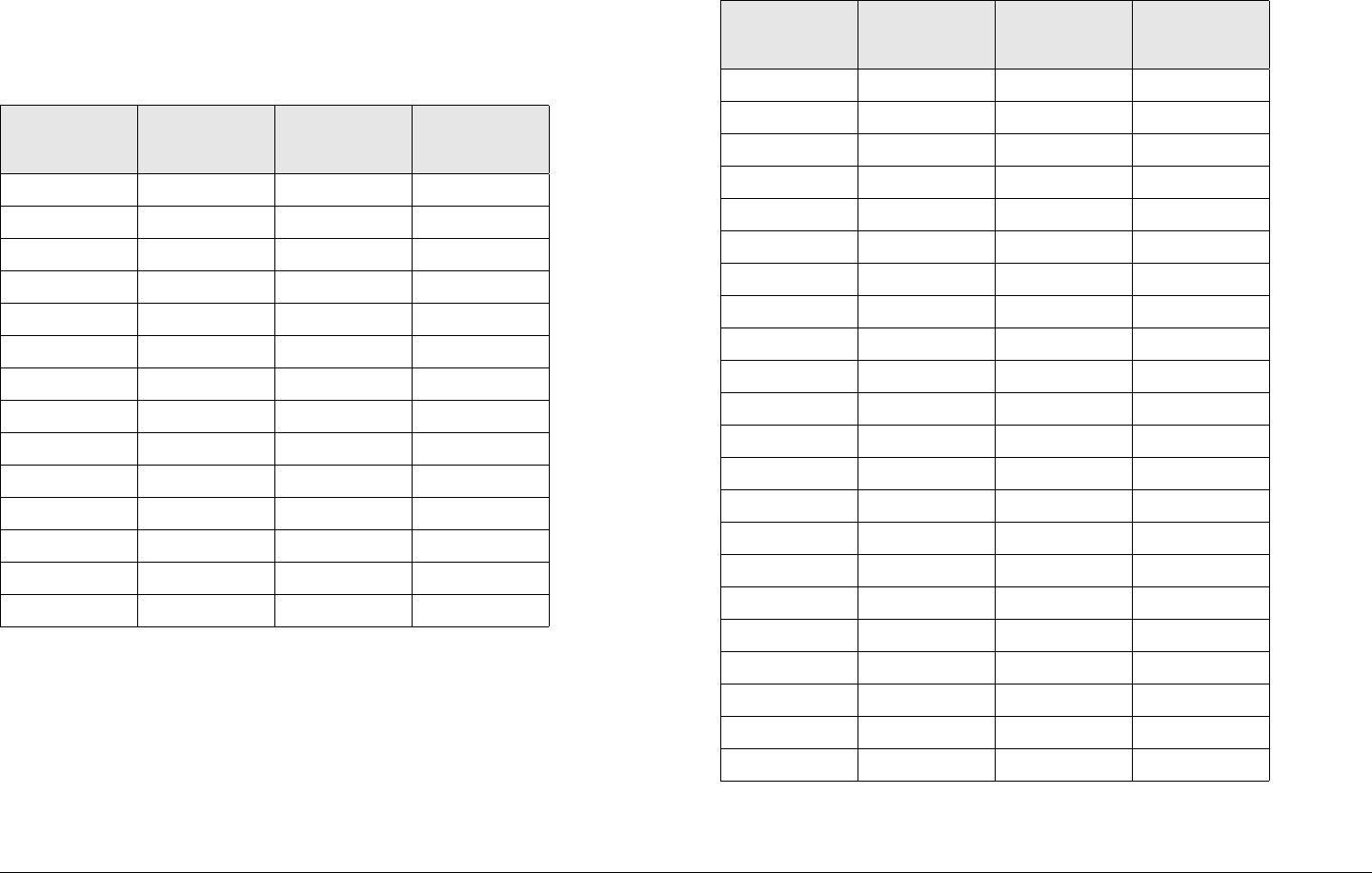
Channels & Frequencies A-6STRATA TX Operator’s Guide/Tech Ref Manual
A.2.10 10.8 to 11.5 GHz Channel Plan
The channel plan for the 10.8 to 11.5 GHz STRATA TX System is
contained in Table A-10.
A.2.11 12.7 to 13.25 GHz Channel Plan
The channel plan for the 12.7 to 13.25 GHz STRATA TX System
is contained in Table A- 11 .
Table A-10: 10.8 to 11.5 GHz Channel Plan
Channel (-) Offset
(MHz)
(0) Center
(MHz)
(+) Offset
(MHz)
1 10805.000 10825.000 10845.000
2 10855.000 10875.000 10895.000
3 10905.000 10925.000 10945.000
4 10955.000 10975.000 10995.000
5 11005.000 11025.000 11045.000
6 11055.000 11075.000 11095.000
7 11105.000 11125.000 11145.000
8 11155.000 11175.000 11195.000
9 11205.000 11225.000 11245.000
10 11255.000 11275.000 11295.000
11 11305.000 11325.000 11345.000
12 11355.000 11375.000 11395.000
13 11405.000 11425.000 11445.000
14 11455.000 11475.000 11495.000
Table A-11: 12.7 to 13.25 GHz Channel Plan
Channel (-) Offset
(MHz)
(0) Center
(MHz)
(+) Offset
(MHz)
1 12706.250 12712.500 12718.750
2 12731.250 12737.500 12743.750
3 12756.250 12762.500 12768.750
4 12781.250 12787.500 12793.750
5 12806.250 12812.500 12818.750
6 12831.250 12837.500 12843.750
7 12856.250 12862.500 12868.750
8 12881.250 12887.500 12893.750
9 12906.250 12912.500 12918.750
10 12931.250 12937.500 12943.750
11 12956.250 12962.500 12968.750
12 12981.250 12987.500 12993.750
13 13006.250 13012.500 13018.750
14 13031.250 03037.500 03043.750
15 13056.250 13062.500 13068.750
16 13081.250 13087.500 13093.750
17 13106.250 13112.500 13118.750
18 13131.250 13137.500 13143.750
19 13156.250 13162.500 13168.750
20 13181.250 13187.500 13193.750
21 13206.250 13212.500 13218.750
22 13231.250 13237.500 13243.750

B
Glossary B-1STRATA TX Operator’s Guide/Tech Ref Manual
Glossary
This section describes acronyms and abbreviations used in
communications, broadcasting, and in our products and
documentation.
Table B-1: Useful Terms
1RU 1 Rack Unit
16 QAM 16-state Quadrature Amplitude Modulation
The signal (video + audio) is imposed onto the 70
MHz carrier by varying both the phase and the
amplitude of the signal while keeping the frequency
constant. There are 16 possible combinations of
phase and amplitude that can be used to carry
information.
3RU 3 Rack Unit
32QAM 32-state Quadrature Amplitude Modulation
The signal (video + audio) is imposed onto the 70
MHz carrier by varying both the phase and the
amplitude of the signal while keeping the frequency
constant. There are 32 possible combinations of
phase and amplitude that can be used to carry
information.
4 FSK 4-state Frequency Shift Keying
8 PSK 8-Phase Shift Keying
8QAM 8-state Quadrature Amplitude Modulation
The signal (video + audio) is imposed onto the 70
MHz carrier by varying both the phase and the
amplitude of the signal while keeping the frequency
constant. There are 8 possible combinations of
phase and amplitude that can be used to carry
information.
64 QAM 64-state Quadrature Amplitude Modulation
The signal (video+audio) is imposed onto the 70 MHz
carrier by varying both the phase and the amplitude
of the signal while keeping the frequency constant.
There are 64 possible combinations of phase and
amplitude that can be used to carry information.
A & C Alarm and Control
ACU AC to DC Converter Unit
ADPCM Adaptive Differential Pulse Code Modulation
AES Audio Engineering Society
AES/EBU Unofficial name for a digital audio standard
developed as a joint enterprise of the AES and the
EBU.
AFC Automatic Frequency Control
AGC Automatic Gain Control
AIS Alarm Indication Signal (all one’s)
AMI Alternate Mark Inversion, line code format for traffic
data.
AVG Average
Table B-1: Useful Terms (Continued)

Glossary B-2STRATA TX Operator’s Guide/Tech Ref Manual
ASI Asynchronous Serial Interface
A serial communications interface operating at
270 Mbit/sec., generally used in field news-gathering
operations.
ASYNC Asynchronous
Digital communication in which there is no timing
requirement for transmission and in which the start of
each character is individually signaled by the
transmitting device.
Baseband A composite signal in which video and audio signals
are combined together, with video occupying
approximately 0-4.5 MHz and audio modulated onto
subcarriers in the 5-6 MHz range. Also called
Composite.
BB Baseband
BDC Block Down Converter
BER Bit Error Ratio
The ratio of bits containing errors to the total number
of bits in the signal, over a time period.
BiasT A type of interconnection between the IDU and the
ODU. In Bias T wiring, IF and DC are combined and
carried on the coax cable up the ODU; blocking
circuitry prevents the DC from entering the IDU.
BISS Basic Interoperable Scrambling System
A means of encrypting and decrypting a digital signal
to prevent unauthorized reception. The encryption
and decryption are controlled by a digital key, which
is shared at both the transmitting and receiving
location.
Table B-1: Useful Terms (Continued)
BISS-1 BISS encryption that uses a fixed key.
BISS-E BISS encryption that uses an encrypted key.
BNC Bayonet lock coaxial connector
BPF Band Pass Filter
bps or b/sec Bits per second
BPSK Binary Phase Shift Keying
BW Bandwidth
CCITT International Telegraph and Telephone Consultative
Committee
A telecommunications standardizing committee of
the ITU.
CCPS Command & Control Power Supply
CENELEC European Committee for Electrotechnical
Standardization
CNR Carrier-to-Noise Ratio
COFDM Coded Orthogonal Frequency Division Multiplexing
Composite
(Baseband)
A band or grouping of frequencies and/or subcarriers,
including video, occupied by the signal in a radio
transmission system. Also called Baseband.
CR4 Code Runner 4
CSI Channel-State Information
CV Composite Video
Video signal in which the chrominance (color) and
luminance (brightness) information are combined in
one signal. S-Video separates the chrominance and
luminance into individual signals.
CW Carrier Wave
DAB Digital Audio Broadcasting
Table B-1: Useful Terms (Continued)

Glossary B-3STRATA TX Operator’s Guide/Tech Ref Manual
dB Decibel
A logarithmic measurement of power or voltage,
applied to audio and RF signals.
dBm A unit of measurement referenced to one milliwatt.
DCC Distribution Command and Control
DCE Data Communications Equipment
A device that communicates with a DTE device. In
practical terms, the DCE is usually a modem and the
DTE device is usually a computer.
De-
emphasis
Reducing the amplitude of high frequency
components of an analog audio signal. Done on the
receive end of an analog link to take out Emphasis
added on the transmit side.
DFT Discrete Fourier Transform
DMUX,
DEMUX
Demultiplexer
DQPSK Differential Quadrature (Quaternary) Phase-Shift
Keying
DRL Data Return Link
DS3 Digital Signal 3
44.736 Mbps data rate.
DTE Data Terminal Equipment
A device that communicates with a DCE device. In
practical terms, the DTE is usually a computer and
the DCE device is usually a modem.
Duplex A channel capable of transmitting information
simultaneously in both directions.
DVB Digital Video Broadcasting
Table B-1: Useful Terms (Continued)
DVB-ASI Digital Video Broadcasting - Asynchronous Serial
Interface
A widely-used MPEG-2 digital transport interface.
Physically the connection is made either with optical
fiber or 75 ohm coax with a BNC connector. Interface
can support data rates up to 270 Mb/sec.
DVB-C Digital Video Broadcasting - Cable
DVB-S Digital Video Broadcasting - Satellite
DVB-T Digital Video Broadcasting - Terrestrial
E1 2.048 Mbps data rate.
E3 34.368 Mbps data rate
EIA Electronic Industries Association
An industry association that establishes various
standards.
EBU European Broadcasting Union
In addition to other activities, EBU produces technical
statements and recommendations for PAL television
systems.
EMC Electromagnetic compatibility.
Emphasis Boosting the amplitude of high frequency
components of an analog audio signal. Done on the
transmit side of an analog link to improve signal-to-
noise ratio.
ENG Electronic News Gathering
ERRS Errors
ESD Electrostatic Discharge
ET Eastern Time (US)
ETSI European Telecommunications Standards Institute
Table B-1: Useful Terms (Continued)

Glossary B-4STRATA TX Operator’s Guide/Tech Ref Manual
EVM Error Vector Magnitude
FCC Federal Communications Commission
The United State's communications regulatory
agency.
FDM Frequency Division Multiplexing
FEC Forward Error Corrections
FFT Fast Fourier Transform
FIFO First In, First Out buffer
FIR Finite Impulse Response
FMT FM Video Modulator or FM Transmitter
FPGA Field Programmable Gate Array
FSK Frequency-Shift Keying
FW Firmware
GHz Gigahertz (109 cycles per second)
GI Guard Interval
GND Ground
GUI Graphic User Interface
HDB3 High Density Bipolar 3 line code format for traffic
data.
HPF High Pass Filter
HPU High Power Unit
H/W or HW Hardware
ICI Inter-Carrier Interference
ICR Inter-City Relay
ID Identification
IDU Indoor Unit
IF Intermediate Frequency
Table B-1: Useful Terms (Continued)
IMD Inter-Modulation Distortion
I/O Input/Output
IRD Integrated Receiver Decoder
IRE 1. Institute of Radio Engineers, an international
professional radio engineering association that
establishes various standards.
2. A unit of measurement, established by the IRE, in
which 1 IRE Unit =.00714 volts peak-to-peak (Vp-p)
and 140 IRE units equals 1 Vp-p.
ISI Inter-Symbol Interference
ISO International Standards Organization
kbps Kilobits per second
kHz Kilo (1,000) cycles per second
LAN Local Area Network
LBO Line Build Out
LCD Liquid Crystal Display
Lcl Local
LED Light Emitting Diode
LIU Line Interface Unit
LNA Low Noise Amplifier
LNB Low Noise Block Down Converter
LNC Low Noise Converter
LO Local Oscillator
LOS Loss of Signal
LPF Low Pass Filter
LQ Link Quality
Mbps Megabits per second
MHz Million (1,000,000) cycles per second
Table B-1: Useful Terms (Continued)

Glossary B-5STRATA TX Operator’s Guide/Tech Ref Manual
MPEG Moving Picture Experts Group
M-QAM M-order of Quadrature Amplitude Modulation
MRC Microwave Radio Communications
Multipath An unpredictable set of reflections and/or direct
waves, each with its own degree of attenuation and
delay. Due to obstacles and reflectors in the wireless
channel, transmitted signals arrive at the received
from various directions over multiple paths.
MUX Multiplexer
NC Normally Closed (Relay or switch contacts)
N/C No Connection
NICAM Near-Instantaneous Companding and Multiplexing
NO Normally Open (Relay or switch contacts)
NRZ Non-Return-to-Zero (Modulation)
NTSC National Television System Committee
Color television standard used in the US. Provides
525 horizontal lines of resolution. Not compatible with
PAL or SECAM.
Null modem
cable
An RS-232 cable designed to connect two computers
(or other data sources) together. It has male DB9
connectors on each end, to mate with the DB9
female connectors on the PCs. It also has the
Transmit and Receive connections crossed over so
Transmit (pin 3) on one end connects to Receive (pin
2) on the other.
Also called “Crossover Cable”.
ODU Outdoor Unit
OFDM Orthogonal Frequency Division Multiplexing
OOK On-Off Keying
Table B-1: Useful Terms (Continued)
PAL Phase Alteration Line
Color television standard used in many European
countries. Provides 625 horizontal lines of resolution.
Not compatible with NTSC or SECAM.
PAL-M Phase Alteration Line
Color television standard used in many European
countries. Provides 625 horizontal lines of resolution
with 50 lines per field. Not compatible with NTSC or
SECAM.
PAL-N Phase Alteration Line
Color television standard used in many European
countries. Provides 525 horizontal lines of resolution
with 60 lines per field. Not compatible with NTSC or
SECAM.
PC Personal Computer
PCR Program Clock Reference
PER Parity Error Rate
ØLK Phase Lock
PID Program Identification
PLL Phase Lock Loop
PRBS Pseudo Random Bit Sequence
QAM Quadrature Amplitude Modulation
QPSK Quadrature Phase Shift Keying
The signal (video+audio) is imposed onto the 70 MHz
carrier by varying the phase of the signal while
keeping the amplitude and frequency constant. There
are 4 possible values of phase that can be used to
carry information.
Table B-1: Useful Terms (Continued)

Glossary B-6STRATA TX Operator’s Guide/Tech Ref Manual
RCL Received Carrier Level
The strength of a received RF signal, in dBm.
RCU Receiver Control Unit
RCL Received Carrier Level
Rcvr Receiver
RD Receive Data
RDS Radio Data System
RF Radio Frequency
RF Level RF Power from the transmitter.
RFU Radio Frequency Unit
RMA Return Material Authorization
RPU Remote Pickup
R-S Reed-Solomon
RSSI Receiver Signal Strength Indicator
RX Receiver
RXU Receiver Unit
RZ Return to Zero
SBE Society of Broadcast Engineers
SC Service Channel
SC Single Carrier
SCM Single Carrier Modem
SD EMB Synchronous Digital Interface Embedded
SDI Synchronous Digital Interface
A serial communications interface operating at
270 Mbit/sec. Generally used for in-studio news
operations.
Table B-1: Useful Terms (Continued)
SECAM Sequence de Couleur Avec Memoire
Color television standard used in France, Russia,
and other countries. Provides 625 horizontal lines of
resolution. Not compatible with NTSC or PAL. Not
supported by this product.
SER Symbol Error Rate
Setpt Set point
SFN Single-Frequency Network
Table B-1: Useful Terms (Continued)

C
Specifications C-1STRATA TX Operator’s Guide/Tech Ref Manual
Specifications
This section provides specifications for the STRATA 2 GHz
Transmitter (TX) System.
Note MRC reserves the right to make changes to
specifications of products described in this
specification sheet at any time without notice and
without obligation to notify any person of such
changes.
MPEG ENCODER SPECIFICATIONS:
SDI Input: . . . . . . . . . . . .. . . . . . . . . ANSI/SMPTE 259M Level C
270Mb/s, 525/625 Component
2 Stereo Audio De-embedding provided AES/EBU
Composite Video: . . . . . . Composite (75 ohms)1 Vpp NTSC/PAL
BNC / Return Loss, Minimum 28 dB at 6MHz
Chroma/Level (Selectable): . . . . . . . . . 4:2:2Profile @ Main Level
or 4:2:0 Profile @ Main Level
Frame Size: . . . . . . . . . . . . . . . . . . . . . Horizontal Res. 720 pixels
Vertical Res: 480/525 NTSC, 576/625 PAL
Video Encoding Rate: . . . 2 to 30 Mbits Constant Bit Rate (4:2:2)
1.5 to 15 Mbits, Constant Bit Rate (4:2:0)
Latency (Selectable) – Bit Rate Dependent
Standard Mode: . . . . . . . . . <200 ms / Low Delay Mode: <100 ms
VBI Processing: . . . . . . . . . . . . . . Extended Picture Mode (4:2:2)
Closed Caption: . . . . . . Supports line 21 (NTSC) CC EIA 608 std
Audio Coding: . . . . . . . . . . . MPEG–II layer 2 (ISO/IEC 13818-3)
ISO/MPEG 11172.3 Layer II (MUSICAM)
Digital Audio Inputs (Configurable): . . .Supports AES/EBU audio
inputs (2 pairs) balanced inputs – 48 KHz sampling
Audio Channels (select): . . . . . . . . Analog audio (2 stereo pairs)
balanced, 600 ohm/600 ohms High Z (selectable)
Min. Audio Bit Rate: . . . . . . . 192 Kbits/channel, 384 Kbits stereo
Lower audio bit rates down to 128 Kbits selectable
Audio Input Levels: . . . . . . . . . . . . . . . . . . . . . +18 dBm clip level
Transport Stream Output: . . . . . . Fully DVB compliant DVB–ASI
per ISO/IEC 13818-2 (188 byte packets) continuous bit rate
Output Monitor Port - Front Panel Connector (70 MHz): . . . . . . . .
Encryption: . . . . . . . . . . . . . . . . . BISS-1, BISS-E
Video input: . . . . . . . . . . . . . . . . . NTSC/PAL, ASI
WAYSIDE CHANNEL:
Embedded data channel on MPEG Module (Uses the RS-232
port for DCE Data Path)
Data Rate: . . . . . . . . . . . . 1200, 2400, 4800, 9600, 19200, 38400
COFDM SPECIFICATIONS:
COFDM IF Output (Monitor): . . . . . . . . . . . . . 70 MHz @ –5 dBm
COFDM Bandwidth (Selectable): . . . . . . . 6 MHz, 7 MHz, 8 MHz
COFDM Carriers: . . . . . . . . . . . DVB-T specifications 2K Carriers
Modulation Type: . . . . . . . . . . . . . . . . . . QPSK, 16QAM, 64QAM
FEC: . . . . . . . . . . . . . . . . . . . . . . . . . . . . . . . 1/2, 2/3, 3/4, 5/6, 7/8
Guard Intervals (Selectable): . . . . . . . . . . . . . . 1/32, 1/16,1/8,1/4
70 MHz Carrier Insert Capability

Specifications C-2STRATA TX Operator’s Guide/Tech Ref Manual
ANALOG AUDIO & VIDEO MODULATOR:
Monitor Outputs: . . . . . . . . . . . . . . . . . . . 70 MHz signal/pass thru
Level output/Impedance: . . . . . . . . . . . +2 dBm Analog/75 Ohms
Signal Inputs: . . . . . . . . . . . . . . . . . . . . . . . . . . .Video, Composite
70 MHz (–10 dBm Analog)
Video Mute: . . . . . . . . . . . . . . . . . . . . . . . 70 MHz test tone - auto
FM Deviation (Selectable): . . . . . . . . . . 3 MHz and 4 MHz - peak
Video Input/Return Loss: . . . . . . . . . . . . . . . . . . 1 Vpp (75 ohms)
525/625 line / > 26 dB
Plug in Video Filter Options: . . . . . . . . . . . . . . . . 4.2, 5.0, 5.5 MHz
Video Response: . . . . . . . . . . . . . . . . ± 0.25 dB@ or within video
filter bandwidth
VIDEO PERFORMANCE:
S/N: . . . . . . . . . . . . . . . . . . . . . . > 68 dB (weighted per RS-250C)
S/H: . . . . . . . . . . . . . . . . . . . . . . > 63 dB (weighted per RS-250C)
Diff. Phase / Gain: . . . . . . . . . . . . . . . . . . . . . . . . . 1 degree / 1 %
Baseband Response: . . . . . . . . . . . . . . . . . . . . . 10 KHz to 8 MHz
+0.5 dB / 8 MHz to 12 MHz <2 dB
Audio Channels: . . . . . . . . . . . . . . . . . . . . . . . . 4 Channel Analog
Line level: +8 dBm ( 600 ohms)
Subcarrier input tune range: . . . . . . . . . . . . 4.5 MHz to 8.59 MHz
Tunable in 2 KHz steps
AUDIO PERFORMANCE:
Frequency Response: . . . . . . . . . . . . . . (40 Hz - 15 KHz):±1.0 dB
(40 Hz - 10 KHz):±0.5 dB
THD: . . . . . . . . . . . . . . . . . . . . 0.5 % @ 1 KHz (75 KHz deviation)
2.0 % @ 1 KHz (200 KHz deviation)
Signal/Noise: . . . . . . . . . . . . . . . . . . . . . . . . . . . . . . 68 dBm (min.)
Output Impedance (select): . . . . . . . . . . 600 ohms bal./10K ohms
Output Level (adjust): . . . . . . . . . . . . . . . . . . +8 dBm - Line Level
nominal (0 dBm to +18 dBm)
Audio channel crosstalk: . . . . . . . . . . . . . . . . . . . . . . . . . . . 60 dB
Emphasis: . . . . . . . . . . . . . . . . . . . . 50 µs/75 µs, flat - Factory set
Control Interface: . . . . . . . . 2 wire serial comm. port as DC input
FRONT PANEL CONTROLS:
Preset, Channel/Offset, TX Attenuation
DISPLAYS:
Analog (FMT): . . . . . . . . . Preset. HPU Status, Frequency, Mode,
Audio, Channel Frequency, Video
Deviation, CW Tone, Error Report
Digital (MPEG/COFDM): . . . . . . Preset. HPU Status, Frequency,
Mode, Modulation, Bandwidth, FEC,
Guard Interval, Video Delay, Audio Mode,
CW Tone, Error Report, RF Power Out
CONFIGURATOR SOFTWARE MENUS:
(RS-232 connection to PC or laptop)
Main: . . . . . . . . . . . . . . . . Connect to Radio, Load Presets, Save
Presets, Select Module Options,
Program Radio, Upload Radio Settings
Radio: . . . . . . . . . . . . . . . . . . . . Operating Mode, Color Bars, CW
Tone, Transmitter Attenuation

Specifications C-3STRATA TX Operator’s Guide/Tech Ref Manual
COFDM: . . . . . . . . . Modulation, FEC, Bandwidth, Guard Interval
MPEG: . . . . . . . . . . . . . . . . . . ASI Bit Rate, Wayside Baud Rate,
Chroma, Delay Mode, BISS Key/ID,
Audio Type, Audio Mode, Audio Input
FMT: . . . . . . . . . . . . . . . . . . . . . . . . Audio Channel Frequency (4),
Pre-Emphasis, Video Deviation
Channel Plan: . . . . Select Frequency +/– Offset, Clear Channel
Plan, Load Default FCC Plan, Load
Channel Plan, Save Channel Plan

Specifications C-4STRATA TX Operator’s Guide/Tech Ref Manual
This page intentionally left blank.

Index
Index-1STRATA TX Operator’s Guide
Numerics
10.0 to 10.7 GHz Channel Plan . . . . . . . . . . . . . . . . . A-5
10.5 to 11.2 GHz Channel Plan . . . . . . . . . . . . . . . . . A-5
10.8 to 11.5 GHz Channel Plan . . . . . . . . . . . . . . . . . A-6
12.7 to 13.25 GHz Channel Plan . . . . . . . . . . . . . . . . A-6
16 QAM . . . . . . . . . . . . . . . . . . . . . . . . . . . . . . . . . . . B-1
3.4 to 3.8 GHz Channel Plan . . . . . . . . . . . . . . . . . . . A-1
4.4 to 5.0 GHz Channel Plan . . . . . . . . . . . . . . . . . . . A-2
6.4 to 7.1 GHz Channel Plan . . . . . . . . . . . . . . . . . . . A-2
6.9 to 7.5 GHz Channel Plan . . . . . . . . . . . . . . . . . . . A-3
64 QAM . . . . . . . . . . . . . . . . . . . . . . . . . . . . . . . . . . . B-1
7.4 to 8.0 GHz Channel Plan . . . . . . . . . . . . . . . . . . . A-3
7.8 to 8.5 GHz Channel Plan . . . . . . . . . . . . . . . . . . . A-4
75 Ohm Coax option . . . . . . . . . . . . . . . . . . . . . . . . . .3-3
8.2 to 8.9 GHz Channel Plan . . . . . . . . . . . . . . . . . . . A-4
A
About This Manual . . . . . . . . . . . . . . . . . . . . . . Notices-i
Accessing the Control Screen . . . . . . . . . . . . . . . . . .3-20
Accessing the Main Screen . . . . . . . . . . . . . . . . . . . .3-20
Accessing the Monitor Screen . . . . . . . . . . . . . . . . . .3-20
ACU
AC INPUT connector . . . . . . . . . . . . . . . . . . . .3-9
Controls, Indicators, and Connectors . . . . . . . .3-8
DC OUTPUT connector . . . . . . . . . . . . . . . . . .3-9
fuse . . . . . . . . . . . . . . . . . . . . . . . . . . . . . . . . . .3-9
power LED . . . . . . . . . . . . . . . . . . . . . . . . . . . .3-9
POWER Switch . . . . . . . . . . . . . . . . . . . . . . . . .3-9
AES . . . . . . . . . . . . . . . . . . . . . . . . . . . . . . . . . . . . . . B-1
AES/EBU . . . . . . . . . . . . . . . . . . . . . . . . . . . . . . . . . . B-1
airborne operations . . . . . . . . . . . . . . . . . . . . . . . . . . 2-3
Aircraft Remote Control Panel . . . . . . . . . . . . . . . . . . 2-9
ASI . . . . . . . . . . . . . . . . . . . . . . . . . . . . . . . . . . . . . . . B-2
Audience, Intended . . . . . . . . . . . . . . . . . . . . . . . . . . 1-2
AUDIO connector . . . . . . . . . . . . . . . . . . . . . . . . . . . . 2-9
AUDIO connectors . . . . . . . . . . . . . . . . . . . . . . . . . . . 3-3
B
Baseband . . . . . . . . . . . . . . . . . . . . . . . . . . . . . . . . . . B-2
BER . . . . . . . . . . . . . . . . . . . . . . . . . . . . . . . . . . . . . . B-2
BiasT . . . . . . . . . . . . . . . . . . . . . . . . . . . . . . . . . . . . . B-2
BISS . . . . . . . . . . . . . . . . . . . . . . . . . . . . . . . . . . . . . . B-2
BISS-1 . . . . . . . . . . . . . . . . . . . . . . . . . . . . . . . . . . . . B-2
BISS-E . . . . . . . . . . . . . . . . . . . . . . . . . . . . . . . . . . . . B-2
BNC . . . . . . . . . . . . . . . . . . . . . . . . . . . . . . . . . . . . . . B-2
C
CENELEC . . . . . . . . . . . . . . . . . . . . . . . . . . . . . . . . . B-2
Channel, Selecting . . . . . . . . . . . . . . . . . . . . . . . . . . 3-31
Channels & Frequencies . . . . . . . . . . . . . . . . . . . . . . A-1
Channels and Frequencies . . . . . . . . . . . . . . . . . . . . A-1
Initial Factory Presets . . . . . . . . . . . . . . . . . . . A-1
Configuration Differences . . . . . . . . . . . . . . . . . . . . . . 2-9
Control
Changing a Preset . . . . . . . . . . . . . . . . . . . . . 3-30
TXU and/or TCU Control Operations . . . . . . . 3-28
Copyright . . . . . . . . . . . . . . . . . . . . . . . . . . . . . . Notices-i
D
DC ON COAX . . . . . . . . . . . . . . . . . . . . . . . . . . . . . . 3-3
DC ON COAX override switch . . . . . . . . . . . . . . . . . 2-10
DC ON COAX switch . . . . . . . . . . . . . . . . . . . . . . . . . 3-3
DC power requirements . . . . . . . . . . . . . . . . . . . . . . . 2-5
Default to Main Screen . . . . . . . . . . . . . . . . . . . . . . . 3-20
Display Messages . . . . . . . . . . . . . . . . . . . . . . . . . . . 4-1
Documents

Index-2STRATA TX Operator’s Guide
Related . . . . . . . . . . . . . . . . . . . . . . . . . . . . . . .1-2
E
E-mail
Technical Support team . . . . . . . . . . . . . . . . . .1-4
Error Codes . . . . . . . . . . . . . . . . . . . . . . . . . . . . . . . . .4-3
Error Messages . . . . . . . . . . . . . . . . . . . . . . . . . . . . . .4-1
F
factory default settings . . . . . . . . . . . . . . . . . . . . . . . .2-6
Frequently Performed Tasks
Changing a Preset . . . . . . . . . . . . . . . . . . . . .3-30
Controlling TCU to TXU DC on Coax . . . . . . .3-33
Powering the STRATA TX System . . . . . . . . .3-12
Preparing for Operation
Mobile Installation . . . . . . . . . . . . . . . . . . .3-10
Mounting to the Tripod . . . . . . . . . . . . . . . .3-11
Portable Deployment . . . . . . . . . . . . . . . . .3-10
Selecting a Channel . . . . . . . . . . . . . . . . . . . .3-31
Setting Monitor Output . . . . . . . . . . . . . . . . . .3-32
Front Panel vs. STRATA TX Configurator Settings . .3-35
G
General System Problems . . . . . . . . . . . . . . . . . . . .4-10
Glossary . . . . . . . . . . . . . . . . . . . . . . . . . . . . . . . . . . B-1
H
How to Use This Manual . . . . . . . . . . . . . . . . . . . . . . .1-1
M
Messages, Error . . . . . . . . . . . . . . . . . . . . . . . . . . . . .4-1
Mobile Installation . . . . . . . . . . . . . . . . . . . . . . . . . . . .2-5
Monitor Output, Selecting . . . . . . . . . . . . . . . . . . . . .3-32
Monitoring
Analog - IF mode . . . . . . . . . . . . . . . . . . . . . .3-20
Analog IF Output . . . . . . . . . . . . . . . . . . . . . . .3-20
COFDM - IF mode . . . . . . . . . . . . . . . . . . . . .3-20
COFDM ASI In mode . . . . . . . . . . . . . . . . . . . 3-20
COFDM Only - ASI In . . . . . . . . . . . . . . . . . . 3-20
DVB-S (Satellite) . . . . . . . . . . . . . . . . . . . . . . 3-20
DVB-S mode . . . . . . . . . . . . . . . . . . . . . . . . . 3-20
MPEG Only ASI Out . . . . . . . . . . . . . . . . . . . 3-20
MPEG/COFDM IF Out . . . . . . . . . . . . . . . . . . 3-20
Using the Monitor Screens in Analog - IF Mode 3-26
Using the Monitor Screens in COFDM - IF Mode 3-24
Using the Monitor Screens in COFDM ASI In Mode 3-25
Using the Monitor Screens in DVB-S Mode . 3-27
Using the Monitor Screens in Ext IF Input Mode 3-23
MRC Technical Support
E-mail . . . . . . . . . . . . . . . . . . . . . . . . . . . . . . . 1-3
MRC Tripod . . . . . . . . . . . . . . . . . . . . . . . . . . . . . . . 3-11
Dovetail Adapter Plates . . . . . . . . . . . . . 3-10, 3-11
Fixed Mounting Bracket . . . . . . . . . . . . . . . . . 3-10
Mounting Plate . . . . . . . . . . . . . . . . . . . . . . . . 3-11
Quick Release . . . . . . . . . . . . . . . . . . . . . . . . 3-10
Universal Mounting Bracket . . . . . . . . . . . . . . 3-11
Multi-Unit Systems . . . . . . . . . . . . . . . . . . . . . . . . . . . 2-3
N
NOT ON CHANNEL message . . . . . . . . . . . . . . . . . . 4-2
O
On-Line Viewing . . . . . . . . . . . . . . . . . . . . . . . . .Notices-ii
Operational Problems . . . . . . . . . . . . . . . . . . . . . . . . 4-8
General System . . . . . . . . . . . . . . . . . . . . . . . 4-10
Video . . . . . . . . . . . . . . . . . . . . . . . . . . . . . . . . 4-9
Ordering Documentation . . . . . . . . . . . . . . . . . . . . . . 1-2
Output, Monitor . . . . . . . . . . . . . . . . . . . . . . . . . . . . 3-32
Overview of Controls, Indicators, and Connectors . . . 3-2
P
Portable Deployment . . . . . . . . . . . . . . . . . . . . . . . . . 2-5
portable operations . . . . . . . . . . . . . . . . . . . . . . . . . . 2-3

Index-3STRATA TX Operator’s Guide
Power Options
TXU and TCU - separate locations . . . . . . . . . .2-4
TXU and TCU co-located . . . . . . . . . . . . . . . . .2-4
Powering the STRATA System
Superimposing DC Power . . . . . . . . . . . . . . . .3-13
Superimposing DC Power with Manual Control 3-13
Powering the STRATA TX System
Single TCU Power Up and Power Down . . . .3-13
Single TXU Power up and Power Down . . . . .3-14
Superimposing DC Power . . . . . . . . . . . . . . . .3-13
TXU and TCU Power Up and Power Down -
Co-Located . . . . . . . . . . . . . . . . . . . . . . . . . . .3-15
TXU and TCU Power Up and Power Down -
Separate Locations . . . . . . . . . . . . . . . . . . . . .3-17
Preparing for Operation . . . . . . . . . . . . . . . . . . . . . . .3-10
Preset, Changing . . . . . . . . . . . . . . . . . . . . . . . . . . . .3-30
Proprietary Material . . . . . . . . . . . . . . . . . . . . . . Notices-i
Q
Quality Certification . . . . . . . . . . . . . . . . . . . . . . Notices-i
R
Regulatory Status . . . . . . . . . . . . . . . . . . . . . . . Notices-i
Remote Control Options . . . . . . . . . . . . . . . . . . . . . . .2-3
Remote Control Panel . . . . . . . . . . . . . . . . . . . . . . . . .2-9
S
Screens . . . . . . . . . . . . . . . . . . . . . . . . . . . . . . . . . . .3-20
Main Screen . . . . . . . . . . . . . . . . . . . . . . . . . .3-20
Single Unit Systems . . . . . . . . . . . . . . . . . . . . . . . . . .2-3
STRATA ACU . . . . . . . . . . . . . . . . . . . . . . . . . . . . . . .2-8
STRATA Aircraft Remote Control Panel
Controls, Indicators, and Connectors . . . . . . . .3-9
controls, indicators, and connectors . . . . . . . . .3-9
STRATA Remote Control Panel
Controls, Indicators, and Connectors . . . . . . . .3-9
STRATA Remote Control Panels . . . . . . . . . . . . . . . . 2-8
STRATA TX Configurator
settings . . . . . . . . . . . . . . . . . . . . . . . . . . . . . . 3-1
STRATA TX Configurator software . . . . . . . . . . . . . . 2-5
STRATA TX System
components . . . . . . . . . . . . . . . . . . . . . . . . . . . 2-2
controls, indicators, and connectors . . . . . . . . 3-2
key features . . . . . . . . . . . . . . . . . . . . . . . . . . . 2-1
STRATA TX System components
ACU . . . . . . . . . . . . . . . . . . . . . . . . . . . . . . . . . 2-3
Remote Control Panels . . . . . . . . . . . . . . . . . . 2-3
TCU . . . . . . . . . . . . . . . . . . . . . . . . . . . . . . . . . 2-3
TXU . . . . . . . . . . . . . . . . . . . . . . . . . . . . . . . . . 2-2
superimposed DC power . . . . . . . . . . . . . . . . . . . . . . 2-5
System
Communications . . . . . . . . . . . . . . . . . . . . . . . 2-5
Components . . . . . . . . . . . . . . . . . . . . . . . . . . 2-7
Configuration . . . . . . . . . . . . . . . . . . . . . . . . . . 2-5
Configurations, Typical . . . . . . . . . . . . . . . . . 2-12
Operation . . . . . . . . . . . . . . . . . . . . . . . . . . . . . 2-5
Options
Antenna . . . . . . . . . . . . . . . . . . . . . . . . . . . 2-3
Deployment . . . . . . . . . . . . . . . . . . . . . . . . 2-5
Mounting . . . . . . . . . . . . . . . . . . . . . . . . . . 2-5
Power . . . . . . . . . . . . . . . . . . . . . . . . . . . . . 2-4
Presets . . . . . . . . . . . . . . . . . . . . . . . . . . . . . . 2-5
System Components
STRATA ACU . . . . . . . . . . . . . . . . . . . . . . . . . 2-7
STRATA Remote Control Panels . . . . . . . . . . 2-7
STRATA TCU . . . . . . . . . . . . . . . . . . . . . . . . . 2-7
STRATA TXU . . . . . . . . . . . . . . . . . . . . . . . . . 2-7
System Description . . . . . . . . . . . . . . . . . . . . . . . . . . 2-1
System Options . . . . . . . . . . . . . . . . . . . . . . . . . . . . . 2-2
System Problems . . . . . . . . . . . . . . . . . . . . . . . . . . . 4-10

Index-4STRATA TX Operator’s Guide
T
TCU
75 Ohm Coax option . . . . . . . . . . . . . . . . . . . . .3-7
Alphanumeric Display . . . . . . . . . . . . . . . . . . . .3-5
alphanumeric display . . . . . . . . . . . . . . . . . . . .3-5
AUDIO Connector . . . . . . . . . . . . . . . . . . . . . . .3-8
AUDIO connector . . . . . . . . . . . . . . . . . . . . . . .3-8
Control Switch . . . . . . . . . . . . . . . . . . . . . . . . . .3-7
Controls, Indicators, and Connectors . . . . . . . .3-5
DC ON COAX . . . . . . . . . . . . . . . . . . . . . . . . . .3-7
DC ON COAX override switch . . . . . . . . . . . .2-11
DC ON COAX Switch . . . . . . . . . . . . . . . . . . . .3-6
DC ON COAX switch . . . . . . . . . . . . . . . . . . . .3-7
FMT module . . . . . . . . . . . . . . . . . . . . . . . . . . .2-8
Monitor (MON) Connector . . . . . . . . . . . . . . . . .3-8
MPEG/COFDM . . . . . . . . . . . . . . . . . . . . . . . . .2-8
POWER connector . . . . . . . . . . . . . . . . . . . . . .3-8
PWR Switch . . . . . . . . . . . . . . . . . . . . . . . . . . .3-6
RS-232 Connector . . . . . . . . . . . . . . . . . . . . . .3-8
RS-232 connector . . . . . . . . . . . . . . . . . . . . . . .3-8
SIGNAL IN Connector . . . . . . . . . . . . . . . . . . . .3-8
SIGNAL IN connector . . . . . . . . . . . . . . . . . . . .3-8
SIGNAL OUT Connector . . . . . . . . . . . . . . . . . .3-8
SIGNAL OUT connector . . . . . . . . . . . . . . . . . .3-8
Status LED . . . . . . . . . . . . . . . . . . . . . . . . . . . .3-6
XMIT LED . . . . . . . . . . . . . . . . . . . . . . . . . . . . .3-6
TCU - New Configuration . . . . . . . . . . . . . . . . . . . . .2-11
TCU - Older Configuration . . . . . . . . . . . . . . . . . . . . .2-11
TCU configuration . . . . . . . . . . . . . . . . . . . . . . . . 2-7, 2-8
TCU to TXU DC on Coax, Controlling . . . . . . . . . . . .3-33
Technical Support . . . . . . . . . . . . . . . . . . . . . . . . . . . .1-3
Troubleshooting . . . . . . . . . . . . . . . . . . . . . . . . . . . . . .4-1
Error Codes . . . . . . . . . . . . . . . . . . . . . . . . . . . .4-3
Error Messages . . . . . . . . . . . . . . . . . . . . . . . . .4-1
Error Status . . . . . . . . . . . . . . . . . . . . . . . . . . . 4-8
general system problems . . . . . . . . . . . . . . . . 4-8
Messages on Display . . . . . . . . . . . . . . . . . . . 4-1
Operational Problems . . . . . . . . . . . . . . . . . . . 4-8
Primary Error Code . . . . . . . . . . . . . . . . . . 4-3, 4-8
Status LED . . . . . . . . . . . . . . . . . . . . . . . . . . . 4-1
Unit ID . . . . . . . . . . . . . . . . . . . . . . . . . . . . . . . 4-8
video problems . . . . . . . . . . . . . . . . . . . . . . . . 4-8
TX
PWR Switch . . . . . . . . . . . . . . . . . . . . . . . . . . . 3-4
TXU
70 MHz COFDM . . . . . . . . . . . . . . . . . . . . . . . 2-7
Alphanumeric Display . . . . . . . . . . . . . . . . . . . 3-3
AUDIO Connector . . . . . . . . . . . . . . . . . . . . . . 3-3
AUDIO connector . . . . . . . . . . . . . . . . . . . . . . 2-9
Control Switch . . . . . . . . . . . . . . . . . . . . . . . . . 3-4
Controls, Indicators, and Connectors . . . . . . . 3-2
Controls, indicators, and connectors . . . . . . . . 3-2
FMT IF . . . . . . . . . . . . . . . . . . . . . . . . . . . . . . . 2-7
FMT module . . . . . . . . . . . . . . . . . . . . . . . . . . 2-7
Front Panel DC ON COAX Switch . . . . . . . . . . 3-2
INPUT Connector . . . . . . . . . . . . . . . . . . . . . . 3-3
MPEG/CODFM module . . . . . . . . . . . . . . . . . . 2-7
POWER IN Connector . . . . . . . . . . . . . . . . . . . 3-4
PWR Switch . . . . . . . . . . . . . . . . . . . . . . . . . . . 3-4
Rear Panel DC ON COAX Switch . . . . . . . . . . 3-5
RF Output Connector . . . . . . . . . . . . . . . . . . . 3-5
RS-232 Connector . . . . . . . . . . . . . . . . . . . . . . 3-5
Status LED . . . . . . . . . . . . . . . . . . . . . . . . . . . 3-4
XMIT LED . . . . . . . . . . . . . . . . . . . . . . . . . . . . 3-3
TXU - New Configuration . . . . . . . . . . . . . . . . . . . . . . 2-9
TXU and TCU
front panel control switches . . . . . . . . . . . . . . . 3-1
integrated system . . . . . . . . . . . . . . . . . . . . . . 2-3

Index-5STRATA TX Operator’s Guide
TXU and/or TCU screens . . . . . . . . . . . . . . . . . . . . .3-20
TXU Controls, Indicators, and Connectors . . . . . . . . .3-2
TXU Front Panel DC ON COAX Switch . . . . . . . . . . .3-2
TXU IF/RF module . . . . . . . . . . . . . . . . . . . . . . . . . . .2-7
TXU or TCU
single-unit applications . . . . . . . . . . . . . . . . . . .2-3
TXU Rear Panel DC ON COAX Switch . . . . . . . . . . . .3-5
U
Unit vs.System Control . . . . . . . . . . . . . . . . . . . . . . .3-20
UNLOCKED message . . . . . . . . . . . . . . . . . . . . . . . . .4-2
Using the Monitor Screens in MPEG Output Mode . .3-21
V
Video Problems . . . . . . . . . . . . . . . . . . . . . . . . . . . . . .4-9
W
Warranty Information . . . . . . . . . . . . . . . . . . . . Notices-iii
All Products . . . . . . . . . . . . . . . . . . . . . . Notices-iii
Product Manufactured by MRC
. . . . . . . . . . . . . . . . . . . . . . . . . . . . . Notices-iii
Products Manufactured By Others . . . . Notices-iii

Index-6STRATA TX Operator’s Guide
This page intentionally left blank.