Midland Radio 713110B Licensed Non-Broadcast Station Transmitter User Manual 1
Midland Radio Corporation Licensed Non-Broadcast Station Transmitter 1
UserManual.wiki
>
Midland Radio
>
713110B User Manual
users manual
Navigation menu
Upload a User Manual
Namespaces
Wiki Guide
HTML
PDF
Info
Views
User Manual
Discussion / Help
Navigation
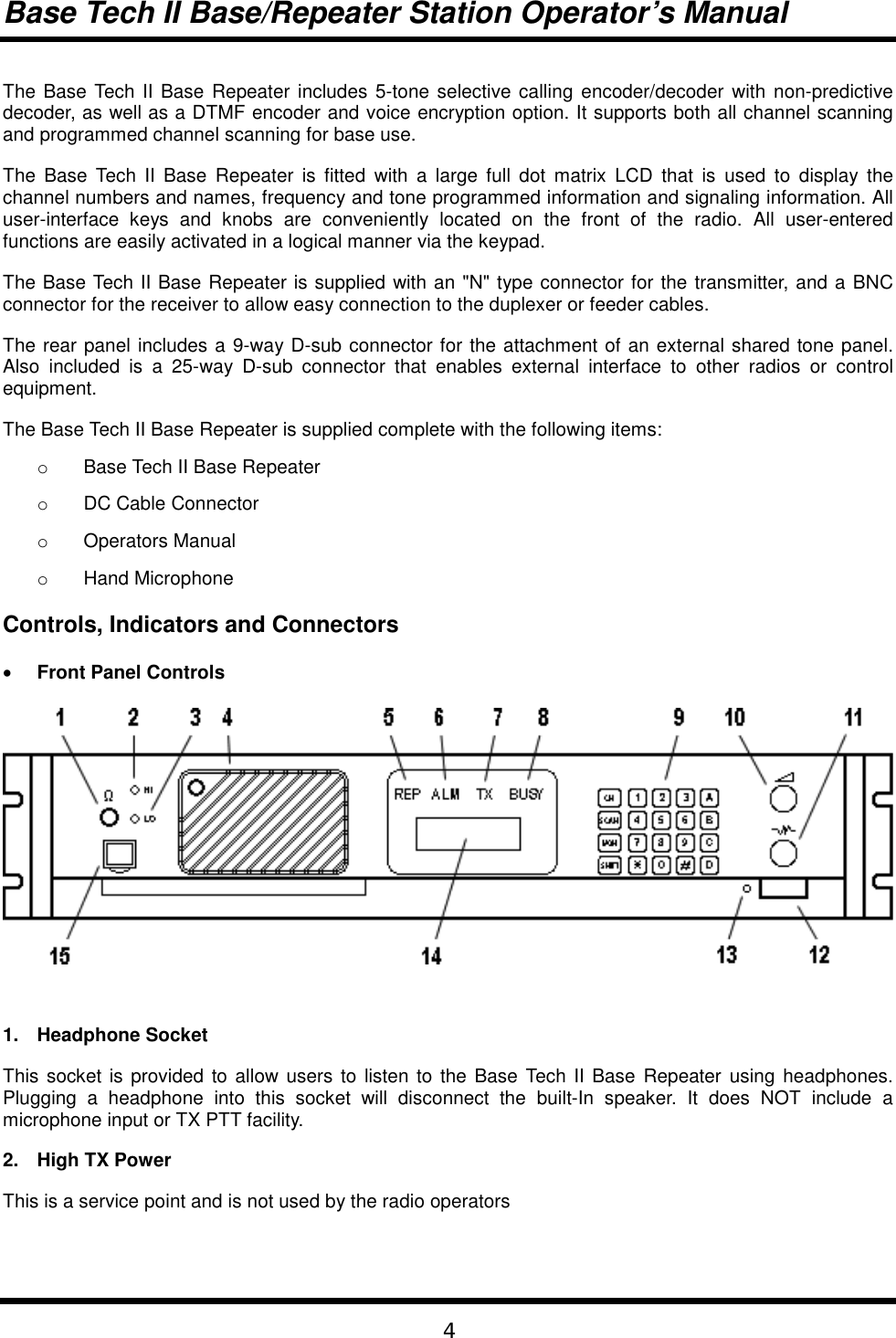
![Base Tech II Base/Repeater Station Operator’s Manual6position.14. Liquid Crystal Display (LCD) (not used on Single Channel Models)The LCD comprises of four (4) lines each of which is capable of displaying twenty-one (21) characters.The first line, under normal operating conditions, displays the strength of the signal being received on theselected channel as a bar graph. The second line displays the strength of the transmitting power as a bargraph. The third line displays the selected channel number (up to four characters) in the first five left handcharacter spaces, and displays the channel name (up to eight characters) in the next eight characterspaces.Any combination of the following characters may be used in the channel name:0-9, A-Z, a-z, / + - * # ! $ % ( ) = [ ] < > ? and spaceThis area of the LCD is left blank when channel names are not used.The six character spaces on the right hand side of this line are used to display status symbols as follows:Symbol StatusThe monitor status.The key lock status.The tone encode status.The scan mode status.The high power transmit status. [SHIFT] key is depressed.On the left hand side of the fourth line, the type of tone signaling system selected by the user isdisplayed. For example, "5TON" indicates 5 Tone signaling while “DTMF” indicates Dual Tone MultiFrequency signaling.The right hand side of the fourth line is used to display data that the user enters (for example, 5 Tonecalling sequences). These character spaces are also used by the Base Tech II Base Repeater to displaymessages and information directed to the user.15. Microphone Input SocketConnect the microphone into this socket.](https://usermanual.wiki/Midland-Radio/713110B/User-Guide-274779-Page-6.png)
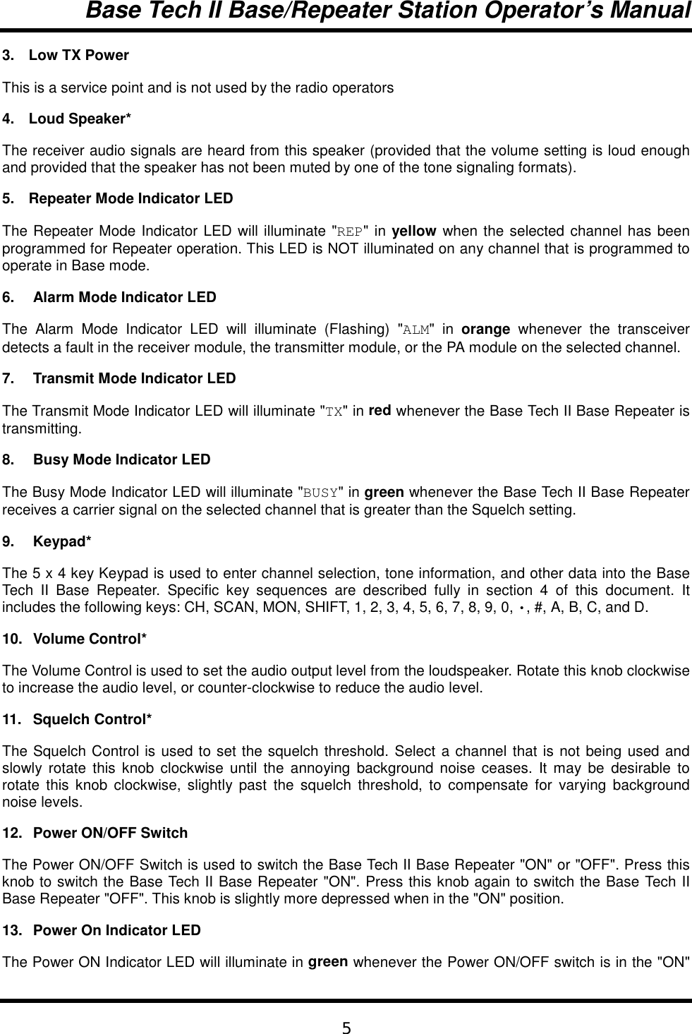
![Base Tech II Base/Repeater Station Operator’s Manual8It is important that the Base Tech II Base Repeater be correctly installed at its working location by aqualified radio technician.As a minimum, it is necessary to:o Connect the DC Input power lead to a suitable 13.8 Volt Regulated DC Power supply that hassufficient capacity. (Ensure that the DC Polarity is correct).o Connect the two antenna connectors to suitable antennas (ensure that the VSWR of theantennas is correct).o Insert the microphone into the microphone connector on the front panel.Basic Operation• Switch OnSwitch the Base Tech II Base Repeater "ON" by pressing the knob (12). Then check that the LEDindicator (13) is illuminated.• Adjust the Volume SettingRotate the Volume Knob (10) clockwise (from the fully counterclockwise position) until the audio levelfrom the speaker is suitable.• Adjust the Squelch SettingRotate the Squelch Knob clockwise (from the fully counter clockwise position) slowly until the backgroundnoise can no longer be heard. It is wise to rotate the knob slightly further in the clockwise direction so thatvariations in the background noise level do not "break" the squelch setting and cause annoying squelchnoises to be heard from the speaker.• Select the ChannelSelect the required channel by pressing the CH key followed by the channel number key. The channelnumber keys must be selected within two seconds. For example, [CH] + [0] + [1] to select Channel 1. TheLCD Display should now display CH01 and (if programmed with a channel label) the channel name:"CH01 NAME".• ReceivingYou should now be able to hear any radio traffic that occurs on channel #1 on the Base Tech II BaseRepeater. It may be necessary to adjust the Volume setting to suit your listening requirements.• TransmittingDepending on the legal requirements in your country, and the operating requirements within yourorganization, it may be necessary to announce your Call Sign. In addition, it will probably be necessary toannounce the Call Sign of the party you are calling at the start of your transmission.When transmitting, it is necessary to hold the microphone about 3 inches from your mouth and speakclearly into the front of the microphone.It is also necessary to press and hold the “Press To Talk” (PTT) bar on the side of the microphone whilespeaking into the microphone.](https://usermanual.wiki/Midland-Radio/713110B/User-Guide-274779-Page-8.png)
![Base Tech II Base/Repeater Station Operator’s Manual9Front Panel OperationThis section describes most signaling and other advanced features that are available on the Base Tech IIBase Repeater. The availability of some features is dependent on the programming of the transceiver andinstalled options. You may find it worthwhile to discuss these features in detail with your radio supplier toobtain a full understanding of their benefits.• Keypad OperationThe Keypad is the interface between the user and the Base Tech II Base Repeater. It is used to enable ordisable various functions and to enter the required data for signaling purposes.The word (5-Tone) or (DTMF) shown after the described feature indicates that the described featureapplies to the particular signaling format.The following keys are used for the purposes described:[0] - [9] Entering new channel numbersEntering the "KILL" passwordEntering signaling encoding numbers (5-Tone) (DTMF)Entering DTMF numbers (DTMF)[A] Advancing the Base Tech II Base Repeater to the next higher channelEntering the signaling "A" tone (5-Tone) (DTMF)Encodes the "A" Tone (DTMF)[B] Advancing the Base Tech II Base Repeater to the next lower channelEntering the signaling "B" tone (5-Tone) (DTMF)Encodes the "B" Tone (DTMF)[C] Entering the signaling "C" tone (5-Tone) (DTMF)Encodes the "C" Tone (DTMF)[D] Entering the signaling "D" tone (5-Tone) (DTMF)Encodes the "D" Tone (DTMF)[•] Displays the previously entered encode numbers (5-Tone) (DTMF)Encodes the "•" -Tone (DTMF)[#] Encodes the signaling numbers that are displayed in the LCD display (5-Tone) (DTMF)Encodes the "#"-Tone (DTMF)[CH] Used with two channel numbers [0] - [9] to change the active channel on the BaseTech II Base Repeater. E.g. [CH]+[9]+[0] will change the active channel to Channel 90(provided Ch 90 has been programmed into the Base Tech II Base Repeater.[SCN] Used to place the Base Tech II Base Repeater into the "All-Scan" mode where theBase Tech II Base Repeater will scan all programmed channels. Pressing the [SCN]key again will cause the Base Tech II Base Repeater to exit from the "All-Scan" mode.[MON] Switches the Base Tech II Base Repeater between "Monitor ON" mode and "MonitorOFF" mode and is used to "Un-mute" the radio when using selective calling(depending on the programming of the Base Tech II Base Repeater).](https://usermanual.wiki/Midland-Radio/713110B/User-Guide-274779-Page-9.png)
![Base Tech II Base/Repeater Station Operator’s Manual10• Keypad Operation using the [SHIFT] KeySome of the Base Tech II Base Repeater's features and related functions can be changed by using the[SHIFT] key. To make these changes, it is necessary to first press the [SHIFT] key followed by the otherkeys within a two second timeframe.The following key sequences are used for the purposes described:[SHIFT]+[0] Toggles the tone system between 5-Tone signaling and DTMF signaling[SHIFT]+[1] Switches the LCD back-light to the ON or OFF position[SHIFT]+[2] Toggles the transmitting power between High power and Low power[SHIFT]+[3] Invalid Key[SHIFT]+[4] Toggles between "Single Tone Encoding" mode and "5-Tone" or "DTMF"signaling mode[SHIFT]+[5] Invalid Key[SHIFT]+[6] Enters the KILL mode to allow entry of the KILL password[SHIFT]+[7] Displays the programmed information for the selected (active) channel in theLCD display[SHIFT]+[8] Locks or Unlocks the Base Tech II Base Repeater's Keypad[SHIFT]+[9] Toggles the Base Tech II Base Repeater between "Normal ChannelScanning" mode and "Priority Channel Scanning" mode[SHIFT]+[A] Restores a channel to the Channel Scanning List. (The user must first selectthe channel to be restored as the active channel)[SHIFT]+[B] Invalid Key[SHIFT]+[C] Indicates to the Base Tech II Base Repeater that you have entered the lastnumber of a DTMF encoding sequence[SHIFT]+[D] Invalid Key[SHIFT]+[•] Deletes the active channel from the Channel Scanning List[SHIFT]+[#] Will attach the "R-Number" data to the active encode number and transmitthe whole sequence[SHIFT]+[CH] Will start or stop the display of the TX and RX bar graphs in the LCD display[SHIFT]+[SCN] Will place the Base Tech II Base Repeater in the Program Scan mode or exitfrom the Program Scan mode[SHIFT]+[MON] Invalid Key](https://usermanual.wiki/Midland-Radio/713110B/User-Guide-274779-Page-10.png)
![Base Tech II Base/Repeater Station Operator’s Manual11• Changing ChannelsTo change to another channel, simply press the [CH] key followed by the number of the required channelwithin two seconds.For example: To select Channel 8, press [CH] [0] [8]To select Channel 99, press [CH] [9] [9]Note that it is always necessary to enter two digits for the Channel Number. The channel # locationdisplayed in the LCD will become blank as soon as the [CH] key is pressed. The cursor will blink at thelocation of the channel number, and display the new numbers as they are entered.It is also possible to change channels by using the [CH], [A] and [B] keys instead of entering the channelnumbers. Pressing the[CH] then the [A] key will advance the channel to the next higher programmedchannel, while pressing [B] will advance the channel to the next lower programmed channel.Note that this action will ignore channels that have not been programmed into the Base Tech II BaseRepeater. Accordingly, the LCD display may appear to advance more than one channel if the missedchannel is not programmed into the Base Tech II Base Repeater.SignalingThe Base Tech II Base Repeater includes some very sophisticated signaling capabilities. We suggest thatyou have your radio supplier conduct some training on the use of these capabilities prior to using them.While it is possible to use these signaling capabilities in both repeater mode, and in base station mode,many will only be useful in practice when the Base Tech II Base Repeater is used in base stationconfiguration.The Base Tech II Base Repeater supports the 5-Tone sequential, and/or the DTMF, and the Single Tonesignaling formats. The required signaling format(s) must be enabled when the Base Tech II BaseRepeater is programmed.• 5-Tone SignalingAvailable Tones5-Tone signaling is commonly referred to as “Selective Calling” (or Selcall) and usually comprises of aseries of 5 tones sequentially transmitted or received in accordance with certain international standards. Itis possible to use longer sequences to enhance the signaling capabilities and to provide additionalfunctions.Accordingly, the Base Tech II Base Repeater will encode up to sixteen (16) tones and decode up to eight(8) tones.These tones can be any of the following letter/number combinations:[0] - [9], and [A] - [D]The most recently entered tone can be recalled and deleted by pressing the [•] key repeatedly.Entering a 5-Tone Encode SequenceWhen switched "ON", the Base Tech II Base Repeater carries out its self-test routine, then waits ready to](https://usermanual.wiki/Midland-Radio/713110B/User-Guide-274779-Page-11.png)
![Base Tech II Base/Repeater Station Operator’s Manual12accept 5-Tone encode numbers. Accordingly, it is necessary to enter the required 5-Tone digits directlyusing the keypad, then pressing the [#] key to transmit the 5-Tone sequence. (Up to sixteen digits can beentered).If it is necessary to enter the "R" number sequence to activate the repeater, the [SHIFT] key must bepressed before pressing the [#] key.If a 5-Tone number is NOT displayed in the LCD, and the [#] key is pressed, then the Base Tech II BaseRepeater will recall the most recent 5-Tone number and transmit it.Recalling the last encoded sequencePressing the [•] will recall the most recent 5-Tone encode sequence and display the sequence in the LCDdisplay. Continuing to press the [•] key will delete the last digit of the sequence until all digits are deleted.In practice, users will usually delete the last one or two digits before entering the new digits.• DTMF SignalingAvailable TonesThe following DTMF tones can be used in any number/letter combination:[0] - [9], [A] - [D], [•], and [#]NOTE: Tone [B] is NOT available if the "Attach Decode No" field in the DTMF Encode Menu has been setto "ON".Up to sixteen (16) DTMF digits can be encoded in one calling sequence.DTMF Tone EntryThere are two methods of entering DTMF tones. The specific tone encoding format is selected during theprogramming of the Base Tech II Base Repeater in the <Main Menu><Encode Set><DTMFEncode><Attach Decode No.> field.Attach Decode No. "OFF" formatPressing the PTT lever first automatically selects the DTMF encoding format and allows direct entry ofDTMF tones.Hold the PTT lever on the microphone while pressing the required DTMF tones. The tones will betransmitted as the keys are being pressed.Attach Decode No. "ON" formatAttach Decode No. "ON" automatically encodes the user’s DTMF decode number after the encodenumber. This can be used for any purpose.Enter the required DTMF tones (up to sixteen tones, except "B" tone) and then transmit the total tonesequence (including the users decode number) by pressing the [#] key. All tones will be transmitted in onecontinuous sequence after pressing the [#] key.Pressing the [•] key will delete the last number entered.Always confirm that the LCD is clear before proceeding, as it may take up to 5 seconds for the tones tobe sent.](https://usermanual.wiki/Midland-Radio/713110B/User-Guide-274779-Page-12.png)
![Base Tech II Base/Repeater Station Operator’s Manual13For example, assume that your decode number is 12345, and that you wish to encode number 12346.You will input 12346, and then press the [#] key. The Base Tech II Base Repeater will encode"12346B12345". The called radio will display “12345” in their LCD indicating the calling party's number is"12345".NOTE: The "B" tone is used as the delimiter in this encoding format and therefore CANNOT be used as aDTMF tone.Pressing the [SHIFT] key and then the [#] will encode ONLY the encode number (and not the decodenumber).Redialing with DTMFIf, during the programming of the Base Tech II Base Repeater, the <Attach Decode No> field has beenset to "OFF", the redialing function operates as follows:Press [SHIFT], then press [#] and the Base Tech II Base Repeater will redial the last encoded DTMFnumber.If, during the programming of the Base Tech II Base Repeater, the <Attach Decode No> field has beenset to "ON", the redialling function operates as follows:Press [#] and the Base Tech II Base Repeater will redial the last encoded DTMF number with the BaseTech II Base Repeater's programmed decode number.Press [SHIFT], then press [#] and the Base Tech II Base Repeater will redial the last encoded DTMFnumber without the Base Tech II Base Repeater's programmed decode number.Restoring the last DTMF number to the LCD DisplayIt is possible to restore the last encoded DTMF number to the LCD display, provided the <Attach DecodeNo> field has been set to "ON" during the programming of the Base Tech II Base Repeater. First, confirmthat the LCD is NOT displaying any DTMF numbers. Then press [V] and the last encoded DTMF numberwill be displayed in the LCD display. It is possible to edit this number at this time by pressing the [V] key(which will erase the last number) or by pressing the required keys to add additional numbers.Encoding DTMF numbers with the 5-Tone system enabledIt is possible to enter DTMF numbers even with the 5-Tone system enabled. This function must beenabled during the programming of the Base Tech II Base Repeater by setting the <DTMF Encode> fieldin the <5Tone Encode Menu> to "ENABLE".To enter a DTMF number (with 5-Tone signaling enabled), the user must press the PTT lever whileentering the first DTMF number. Second and subsequent numbers do NOT require the PTT lever to bepressed, provided all numbers are entered within a few seconds (before the display reverts to 5-Tonemode and displays "5TON" in the LCD display).• Single Tone EncodingThe Base Tech II Base Repeater has the ability to encode one of six single tone frequencies for 1, 2, 3, or4 seconds. This function is enabled during programming of the Base Tech II Base Repeater by selectingthe <Single Tone ON> field in the <Encode Menu>, and setting the encode period.Press the [SHIFT] and the [4] keys to put the Base Tech II Base Repeater into Single Tone Encodingmode. "S1" and the tone frequency ("xxxxHz") will be displayed in the tone area of the LCD display forabout 4 seconds until the Base Tech II Base Repeater reverts back to the normal signaling mode.](https://usermanual.wiki/Midland-Radio/713110B/User-Guide-274779-Page-13.png)
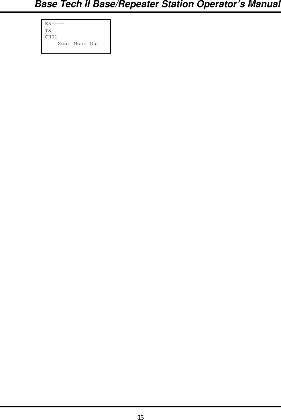
![Base Tech II Base/Repeater Station Operator’s Manual14While the Base Tech II Base Repeater is in Single Tone Encoding mode, it is possible to advance to thenext tone frequency by pressing the [A] key, or to return to the previous tone by pressing the [B] key.Pressing the [#] key will encode the displayed tone (for the programmed time period). It also automaticallyexits the Single Tone Encoding mode and returns the Base Tech II Base Repeater to the normal signalingmode.ScanningThe Base Tech II Base Repeater is supplied with two scanning modes. These are All Channel Scan modein which the Base Tech II Base Repeater will scan all channels that are programmed into the Base Tech IIBase Repeater, and the Program Channel Scan mode in which the Base Tech II Base Repeater will scanonly the channels that have been designated during the programming of the Base Tech II Base Repeater.One HIGH priority and one LOW priority scan channel can be set for each scan mode during theprogramming of the radio.• All Channel Scan OperationPressing the [SCAN] key places the Base Tech II Base Repeater into All Channel Scan mode. The Scanmode symbol "•" is displayed in the LCD display. Also the LCD will also display "All Scan Mode-in"for two seconds as shown below: RX====TXCH01 ∞ All Scan ModeIn• Program Channel Scan OperationPressing the [SHIFT] and then the [SCAN] key places the Base Tech II Base Repeater into ProgramChannel Scan mode. The Scan mode symbol "•" is displayed in the LCD display. The LCD will alsodisplay "PRG Scan Mode-in" for two seconds as shown below:RX====TXCH01 ∞ PRG Scan ModeIn• Exiting All Channel Scan and Program Channel Scan modesPressing the [SCAN] key will take the Base Tech II Base Repeater out of either scanning mode and returnthe Base Tech II Base Repeater to normal mode. The scan symbol "•" will be removed from the LCDdisplay. The LCD will display "Scan Mode-out" for two seconds as shown below:](https://usermanual.wiki/Midland-Radio/713110B/User-Guide-274779-Page-14.png)
![Base Tech II Base/Repeater Station Operator’s Manual16• Priority ScanningThe Base Tech II Base Repeater allows users to enter the required scanning mode first, then enablePriority Scanning for the particular scanning mode chosen.Pressing the [SHIFT] key then the [9] key places the Base Tech II Base Repeater into Priority Scanningmode as shown below:RX====TXCH01 Priority ScanPressing the [SHIFT] and the [9] key again will take the Base Tech II Base Repeater out of Priority Scanmode and return it to the Normal Scan mode as shown below:RX====TXCH01 ∞ Normal Scan• Removing an Active Channel from the Scan ListIt is possible to temporarily delete an active channel from the scan list by pressing [SHIFT] and the [•] keyand holding them down for more than one second. Multiple channels can be deleted from the Scan list,provided that at least one channel remains in the Scan List.A "beep" sound from the radio confirms correct deletion of the channel from the scan list. This functionCANNOT be used in the Priority Scan mode. The Base Tech II Base Repeater automatically restores allchannels to their respective scanning list as soon as the Base Tech II Base Repeater exits from the scanmode.• Restoring Channels to the Scan ListChannels can be restored to the scanning list without exiting from the scan mode by pressing the [SHIFT]key and pressing and holding the [A] key for more than one second. This action will restore all channelsto the scan list. This action CANNOT be used in the Priority Scan mode.](https://usermanual.wiki/Midland-Radio/713110B/User-Guide-274779-Page-16.png)
![Base Tech II Base/Repeater Station Operator’s Manual17Locking the KeypadPressing the [SHIFT] key and then the [8] key will lock all keys (except the [SHIFT] and [MON] keys) onthe Base Tech II Base Repeater's keypad to prevent accidental or inadvertent data entry. After pressingthe [SHIFT] and [8] keys, the keypad becomes locked and the Key-Lock symbol “•” is displayed in theLCD display. The display also shows "Key-Lock" for two seconds as shown below:RX====TXCH01 Key LockPressing [SHIFT] and [8] again will Unlock the keypad, remove the Key-Lock symbol from the LCDdisplay, and display "Key-Unlock" in the LCD display for two seconds as shown below:RX====TXCH01 Key UnlockChanging Tone Signaling SystemsIt is possible to switch the Base Tech II Base Repeater's tone signaling system among 5-Tone sequentialsignaling, DTMF signaling and Non (No-Tone), providing the <Miscellaneous Menu> <Tone SystemChange> field was set to "ENABLE" during the programming of the Base Tech II Base Repeater.Press [SHIFT] and hold down the [0] key for more than one second to change among the 5-Tone system,DTMF system and Non system. The new signaling system will show up on the LCD display as follows:RX====TXCH01 System is DTMFPressing [SHIFT] and holding down the [0] key for more than one second again will change the BaseTech II Base Repeater to the next signaling system. The new signaling system will show up on the LCDdisplay as shown below:RX====TXCH01 System is Non](https://usermanual.wiki/Midland-Radio/713110B/User-Guide-274779-Page-17.png)
![Base Tech II Base/Repeater Station Operator’s Manual18Displaying the Channel InformationThe Base Tech II Base Repeater can display information pertaining to the selected channel (provided thatthe <Miscellaneous Menu> <Information Display> field was set to "ENABLE" during the programming ofthe radio).This information includes:o The RX frequency of the selected channel.o The TX frequency of the selected channel.o The channel spacing for the selected channel (Wide or Narrow).o The operating mode for the selected channel (Base, Repeater, Simplex, Duplex)o The RX CTCSS/DCS tone for the selected channel (provided CTCSS/DCS has beenprogrammed for use on the selected channel).o The TX CTCSS/DCS tone for the selected channel (provided CTCSS/DCS has beenprogrammed for use on the selected channel).o The tone encoding format (providing 5-Tone signaling was selected during programming of theBase Tech II Base Repeater).o The tone set (providing 5-Tone signaling was selected during programming of the Base Tech IIBase Repeater).o The ANI mode.o The tone decoding set (provided 5-Tone or DTMF signaling was selected during programming ofthe Base Tech II Base Repeater).o The decode number (provided 5-Tone or DTMF signaling was selected during programming ofthe Base Tech II Base Repeater).To view this information in the LCD display, first select the required channel. Then press the [SHIFT] key,then the [7] key. You will need to keep the [7] key pressed until the Base Tech II Base Repeater hascycled through the information steps.This function is NOT available if the <Miscellaneous Menu> <Information Display> field has been set to"DISABLE" during the programming of the Base Tech II Base Repeater.Display of Received Tone Frequencies.It is possible to set the Base Tech II Base Repeater to display the received tone frequencies in the LCDdisplay. They will appear in the area normally used to display the strength of the received signals.Press [SHIFT] and then press [D] to enable this function.Once enabled, the LCD will show "RCV" in the area of the LCD display that normally shows the strengthof the received signal, as well as, "Tone Display on" for two seconds as shown below:RCVTXCH01 Tone Display On](https://usermanual.wiki/Midland-Radio/713110B/User-Guide-274779-Page-18.png)
![Base Tech II Base/Repeater Station Operator’s Manual19Whenever a tone frequency is decoded, the frequency number will be displayed in the LCD display to theright of "RCV" as shown below:RCV 12345TXCH015TONPressing the [SHIFT] key, then the [D] key once again will disable this function and return the LCD displayto normal as shown below:RXTXCH01 Tone DisplayOffBar Graph DisplaysThe Base Tech II Base Repeater will normally show the strength of the received signal to the right of "RX"in the LCD display and the strength of the transmitted signal to the right of "TX" in the LCD display. Bothwill be displayed in the form of a bar graph.This function can be disabled by pressing the [SHIFT] key, then the [CH] key. The LCD display willindicate "RX Display Off" and "TX Display Off" as shown below:RX Display OffTX Display OffCH01Pressing the [SHIFT] key, then the [CH] key once again will return the Base Tech II Base Repeater tonormal. The LCD display will show the normal bar graph display for both the RX signal strength and TXsignal strength.LCD Display Back LightThe LCD Display has a Back-Light to illuminate the display. It normally switches "ON" whenever any keyor the PTT lever is pressed, and will remain illuminated for five seconds. Some users may prefer theBack-Light to remain illuminated to assist viewing the LCD display in poor viewing situations.Press the [SHIFT] key, then press the [1] key for more than one second and the LCD Back-light willremain illuminated.When finished, press the [SHIFT] key and then press the [1] key for more than one second and the LCD](https://usermanual.wiki/Midland-Radio/713110B/User-Guide-274779-Page-19.png)
![Base Tech II Base/Repeater Station Operator’s Manual20Back-light will revert to normal operation.Transmit Power ChangeIt is possible to change the Base Tech II Base Repeater's transmit power from the high power setting tothe low power setting (and vice versa) from the keypad, provided that this function has been enabledduring the programming of the Base Tech II Base Repeater.To enable this function, the <Miscellaneous Menu> <TX Power Change> field must be set to "ENABLE".Press the [SHIFT] key, then the [2] key and the Base Tech II Base Repeater will change from the hightransmit power setting to the low transmit power setting. The "•“ symbol will be removed from the thirdline of the LCD display.Press the [SHIFT] key and the [2] key a second time, and the Base Tech II Base Repeater will changefrom the low transmit power setting to the high transmit power setting. The "•" symbol will be displayed inthe third line of the LCD display.If this function is NOT required, the <Miscellaneous Menu> <TX Power Change> field must be set to"DISABLE".Calling Party ID DisplayThe Base Tech II Base Repeater has the capability to display a calling radio's ID (ANI) number after beingcalled. When the Base Tech II Base Repeater is called, "CALL" will be displayed on the fourth line of theLCD display (and continue to flash). The calling radio's ID number will be displayed to the right of "CALL"as shown below:RXTXCH01CALL 12346If the Base Tech II Base Repeater user presses the [#] key (when "CALL" is flashing and the caller's IDnumber is displayed), the Base Tech II Base Repeater will automatically call the identified radio.In the case of 5-Tone signaling systems, this function is enabled in the <5Tone Encode Menu> <EncodeFormat> field, by selecting one of the following parameters:"Encode + B + Decode""Encode + A.Pause + Decode""Decode + A.Pause + Encode""Encode + ANI"In the case of DTMF signaling systems, this function is enabled by setting the <DTMF Encode Menu><Attach Decode No> field to "ON" during the programming of the Base Tech II Base Repeater.](https://usermanual.wiki/Midland-Radio/713110B/User-Guide-274779-Page-20.png)
![Base Tech II Base/Repeater Station Operator’s Manual21Displaying any Radio's ID NumberThe Base Tech II Base Repeater has the capability to display any calling radio's ID (ANI) number. Whenthe Base Tech II Base Repeater receives an ANI number, "DISP" will be displayed on the fourth line ofthe LCD display (and continue to flash). The radio's ID number will be displayed to the right of "DISP" asshown below:RXTXCH01DISP 1234In the case of 5-Tone signaling systems, this function is enabled by setting the <5Tone Decode Menu><ANI Receive> field to "ON" during the programming of the Base Tech II Base Repeater.In the case of DTMF signaling systems, this function is enabled by setting the <DTMF Decode Menu><ANI Receive> field to "ON" during the programming of the Base Tech II Base Repeater.Emergency Caller DisplayThe Base Tech II Base Repeater has the ability to accept and display emergency calls from other radioswithin the radio system.This function is enabled by setting the <Emg Call Receive> field to "ON" in the <5Tone Decode Menu> or<DTMF Decode Menu> during the programming of the radio.The calling (Emergency) radio must encode its emergency data in the following format:"000" + the calling radio's ID (decode number).This format applies to both 5-Tone and DTMF signaling systems.When the Base Tech II Base Repeater receives an emergency call, it will sound a warning tone from thespeaker. The LCD will display "EMG" (flashing) in the fourth line, and display the emergency radio's ID tothe right of "EMG" as shown below:RXTXCH01EMG 12346Upon receipt of an emergency call, the Base Tech II Base Repeater will automatically respond to theemergency radio by sending the emergency radio's ID number to it.If the Base Tech II Base Repeater user presses the [#] key, the Base Tech II Base Repeater will resendthe emergency radio's ID number.While the Base Tech II Base Repeater is in the Emergency Mode, all keys (except the [#] key) on thekeyboard become disabled.](https://usermanual.wiki/Midland-Radio/713110B/User-Guide-274779-Page-21.png)
![Base Tech II Base/Repeater Station Operator’s Manual22Pressing the [SHIFT] key and the [•] key will return the Base Tech II Base Repeater to the normaloperating mode.Automatic Transmit in Repeater ModeThe Base Tech II Base Repeater can be programmed to automatically repeat valid incoming messages.First, the active channel of the Base Tech II Base Repeater must be programmed to operate as arepeater. It must then receive a carrier frequency on the designated channel. If the Base Tech II BaseRepeater has been programmed for CTCSS or DCS operation, it must also receive a valid CTCSS orDCS tone. It will then automatically retransmit any received signals.When the Base Tech II Base Repeater ceases to receive a carrier frequency, or a valid CTCSS or DCStone, it activates the <Auto TX Reset Time> timer. This will keep the Base Tech II Base Repeaterrepeating (for up to 9.9 seconds depending on the programming of the Base Tech II Base Repeater), andallow other users with a valid CTCSS or DCS tone to access the repeater.TX Test ModeThe Base Tech II Base Repeater comes equipped with a TX (Transmit) Test Mode. When the Base TechII Base Repeater is placed in the TX Test Mode, it will transmit a carrier frequency modulated with a 1kHztone on the selected active channel. It is possible to change channels while in TX Test Mode.Pressing the [SHIFT] key, then the [B] key places the Base Tech II Base Repeater in TX Test Mode anddisplays the message in the LCD as shown below:RXTXCH01TXT TX Test Mode-inPressing the [SHIFT] key and the [B] key a second time will return the Base Tech II Base Repeater tonormal mode and displays the message in the LCD as shown below:RXTXCH01TXT TX Test Mode-outKeypad Test ModeThe Base Tech II Base Repeater comes equipped with a Keypad Test Mode that allows the user toelectrically test all keypad keys as well as the PTT Key.Holding the [C] key while switching the POWER SWITCH "ON" places the Base Tech II Base Repeater inKeypad Test Mode and displays the message in the LCD Display as shown below:KEY TESTPlease Key-in](https://usermanual.wiki/Midland-Radio/713110B/User-Guide-274779-Page-22.png)
![Base Tech II Base/Repeater Station Operator’s Manual24Then press the keys to be tested one at a time. The respective key will be displayed in the LCD when thekey is operating correctly. For example, if you press the [CH] key, the LCD Display will indicate correctoperation as shown below:KEY TESTCH KeySwitch the Base Tech II Base Repeater "OFF" to exit the Keypad Test Mode.Frequency Band Test ModeIt is possible to display the Base Tech II Base Repeater's operating Frequency Band in the LCD displaywhen in Frequency Band Test Mode.Holding the [B] key while switching the POWER SWITCH "ON" places the Base Tech II Base Repeater inFrequency Band Test Mode and displays the operating Frequency Band in the LCD Display as shownbelow:<PLL Band Check>>40D OK"40D" indicates the frequency band for a particular Base Tech II Base Repeater radio.Switch the Base Tech II Base Repeater "OFF" to exit the Frequency Band Test Mode.Starting MessageWhen the Base Tech II Base Repeater is Switched "ON", it will display a Starting Message in the LCDdisplay for two seconds. The default Starting Message (using all dots) is shown below:!!!!!!!!!!!!!!!!!!!!!!!!!<51BS V095 510>!!!!!!!!!!!!A personalized message for your business may be shown as the Starting Message. If you require apersonalized message, then it should be entered in the <Miscellaneous Menu> <Starting Message> fieldduring the programming of the radio. Such a message is shown below: Securicor Wireless<51BS V095 510>](https://usermanual.wiki/Midland-Radio/713110B/User-Guide-274779-Page-24.png)
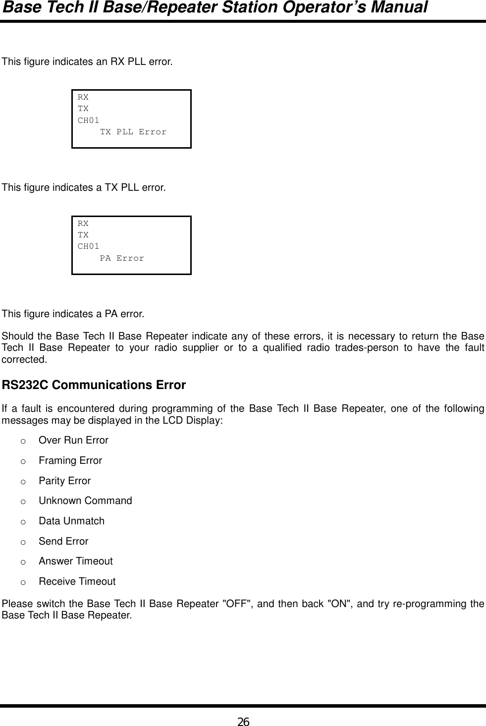
![Base Tech II Base/Repeater Station Operator’s Manual25 Serial Number DisplayIt is possible to display the Base Tech II Base Repeater's Serial Number in the LCD Display. To do so, theserial number must be entered into the <Configuration Menu> <Serial No.> field during the programmingof the radio. The serial number can be up to eight characters long and can comprise of any of thesecharacters:"A - Z" & "0 - 9".Holding the [D] key while switching the POWER SWITCH "ON" places the Base Tech II Base Repeater inSerial Number Display Mode and displays the Base Tech II Base Repeater's Serial Number in the LCDDisplay as shown below:Serial KY000727Switch the Base Tech II Base Repeater "OFF" to exit from the Serial Number Display Mode.EEROM Data Check ModeAs soon as the Base Tech II Base Repeater is switched "ON", it will automatically read and check all thedata in the EEROM. If this check finds damaged or corrupted data, the Base Tech II Base Repeater willautomatically enter the Programming Mode and display the following message in the LCD Display:EROM Data ErrorShould this happen, it is necessary to return the Base Tech II Base Repeater to your radio supplier or to aqualified radio trades-person who has the facilities to re-program the Base Tech II Base Repeater.Hardware Error DetectionThe Base Tech II Base Repeater automatically tests for certain hardware faults or failures, and when afault is found, it will blink the "ALM" LED display above the LCD Display and indicate the nature of the faultin the LCD Display as shown below:RXTXCH01 RX PLL Error](https://usermanual.wiki/Midland-Radio/713110B/User-Guide-274779-Page-25.png)