Midland Radio 77321 CB Radio with Weather Alert User Manual 10002 06
Midland Radio Corporation CB Radio with Weather Alert 10002 06
Users Manual

FRONT COVER GOES HERE
Part No:
Title:
Author:
Output Date:

IMPORTANT NOTICE!
Safety Definitions
Statements in this manual preceded by the following words
are of special significance:
WARNING indicates a potentially hazardous situation
which, if not avoided, could result in death or serious
injury. (00119a)
CAUTION indicates a potentially hazardous situation
which, if not avoided, may result in minor or moderate
injury. (00139a)
CAUTION used without the safety alert symbol indicates
a potentially hazardous situation which, if not avoided,
may result in property damage. (00140a)
Printed in the U.S.A
NOTE
Refers to important information and is placed in italic type. It
is recommended that you take special notice of these items.
HARLEY-DAVIDSON MOTORCYCLES ARE
FOR ON-ROAD USE ONLY
This motorcycle is not equipped with a spark arrester and is
designed to be used only on the road. Operation of off-road
usage in some areas may be illegal. Obey local laws and
regulations. This manual should be considered a permanent
part of the motorcycle and should remain with the motorcycle
when resold.
VISIT THE HARLEY-DAVIDSON WEB SITE
http://www.harley-davidson.com
WARNING
CAUTION
CAUTION

CMI-X.X-06/05
Printed in the U.S.A.
YOUR OWNER'S MANUAL
WE CARE ABOUT YOU
Welcome to the Harley-Davidson®Motorcycling Family! When enjoying your Harley-Davidson motorcycle, be sure to ride
safely, respectively and within the limits of the law. Always wear a helmet, proper eyewear and protective clothing, and insist
your passenger does too. Never ride while under the influence of alcohol or drugs. Know your Harley®and read and
understand your owner's manual from cover to cover. Sign up for a Harley-Davidson Rider's Edge®Course (call 1-800-588-
2743 for a course near you) or a Motorcycle Safety Foundation rider course (call 1-800-446-9227 for a course near you).
Protect your privilege to ride by joining the American Motorcyclist Association. Visit www.ama-cycle.org for more information.
Your new Harley-Davidson motorcycle is designed and manufactured to be the finest in its field. Your Harley-Davidson
motorcycle conforms to all applicable U.S. Federal Motor Vehicle Safety Standards and U.S. Environmental Protection Agency
regulations effective on the date of manufacture.
This manual has been prepared to acquaint you with the operation, care and maintenance of your motorcycle and to provide
you with important safety information. Follow these instructions carefully for maximum motorcycle performance and for your
personal motorcycling safety and pleasure.
Your Owner's Manual contains instructions for operation and minor maintenance. Major repairs are covered in the Harley-
Davidson Service Manual. Such major repairs require the attention of a skilled technician and the use of special tools and
equipment. Your Harley-Davidson dealer has the facilities, experience and Genuine™Harley-Davidson®parts necessary to
properly render this valuable service. We recommend that any emission system maintenance be performed by an authorized
Harley-Davidson dealer.
Harley-Davidson Motor Company ©2005 H-D.

CUSTOMER SERVICE ASSISTANCE
Most sales or service issues will be resolved at the dealership. However if an issue arises that your dealer cannot resolve,
please follow the procedure below.
1. Discuss your problem with the appropriate personnel at the dealership in the Sales, Service or Parts area. If that proves
unsuccessful, speak to the owner of the dealership or the general manager.
2. If you cannot resolve the issue with the dealership, you can contact the Harley-Davidson Customer Service Department by
calling (414) 343-4056 or write to:
Attention: Customer Service Department
Harley-Davidson Motor Company
P. O. Box 653
Milwaukee, WI 53201
To avoid delays, please have the following information available to give to the Customer Service Representative:
* Your name, address and phone number.
* Motorcycle V.I.N. (Vehicle Identification Number) found on the vehicle registration or stamped on the steering head
and on a label located on the motorcycle itself.
* Name and location of the dealership.
* Current mileage.
* Clear description of issue.

This owner’s manual illustrates and describes features that are standard or are available as extra cost options. Therefore, some
of the equipment shown in this publication may not be on your motorcycle.
Harley-Davidson reserves the right to change specifications, equipment or designs at any time without notice and without
incurring obligation.
PERSONAL INFORMATION
Name:
Address:
City: State: Zip:
Telephone:
Vehicle Identification Number:
Ignition Key Number:
Security System Personal Code:
-- -- -- --
DEALER INFORMATION
Name:
Address:
City: State: Zip:
Telephone:
Sales Contact:
Service Contact:
Parts Contact:


2006 SOUND SYSTEM
Advanced Audio System....................................................1
Stereo Receiver.................................................................2
Front Panel Controls..........................................................3
ON..............................................................................3
1, 2, 3, 4, 5/Left Arrow................................................3
6..................................................................................3
5/Left, Up, Down, Right Arrows...................................4
OK...............................................................................4
COM...........................................................................4
INT..............................................................................4
NAV.............................................................................4
LCD.............................................................................4
CD Door......................................................................4
EJECT........................................................................4
AUX.............................................................................5
Left Handlebar Controls.....................................................7
+/AUDIO/- Switch........................................................7
PTT and +/SQ/- Switch...............................................7
Right Handlebar Controls...................................................9
UP/MODE SEL/DN Switch.........................................9
Receiver Operation..........................................................11
Set Time-of-Day........................................................11
Turn Receiver ON/OFF.............................................11
Select a Frequency Band..........................................12
Volume......................................................................12
AM vs FM Reception................................................12
AM............................................................................12
FM.............................................................................12
FM Stereo vs FM Mono............................................12
WB............................................................................13
Tuning-in a Radio Station..........................................13
Manual Tuning...........................................................13
SEEK Tuning.............................................................13
SCAN Tuning............................................................13
Preset Memory/Tuning..............................................14
PRESET SCAN Tuning.............................................14
Adjusting Volume......................................................14
Mixing Bass and Treble.............................................15
Adjusting AVC...........................................................15
Adjusting Display Contrast........................................17
CD/MP3 Operation...........................................................18
Auto Load..................................................................18
Disc Error 1...............................................................19
Eject..........................................................................19
Tracks........................................................................19
Fast Advance and Reverse.......................................19
Random....................................................................20
i
TABLE OF CONTENTS

Scan..........................................................................20
Repeat......................................................................20
MP3..........................................................................20
Recommendations for Handling CDs...............................21
Intercom and Citizen Band with Passenger Speakers.....22
Headsets and Sockets.....................................................23
VOX Microphones............................................................24
Speaker Controls.............................................................25
SPKR Switch............................................................25
Rider to Passenger Speaker Balance.......................25
Passenger Controls..........................................................26
UP/MODE SEL/DN Switch.......................................26
PTT and +/VOL/- Switch...........................................26
Sidecar Controls..............................................................29
MODE and +/TUNE/- Switch....................................29
PTT/+/VOL/-..............................................................29
Intercom Operation..........................................................30
Operation..................................................................30
Activating the Intercom and the VOX Microphones....30
Adjusting VOX Sensitivity..........................................31
Adjusting Rider Headset Volume..............................31
Adjusting Passenger Headset Volume......................32
CB Operation...................................................................32
Activating the CB......................................................32
Entering CB Setup....................................................32
Selecting a Channel..................................................33
Adjusting Squelch.....................................................33
Transmitting...............................................................33
Adjusting Volume......................................................34
CB Range.................................................................34
Audio Routing and Mixing................................................36
General.....................................................................36
Troubleshooting................................................................39
Operational Troubleshooting.....................................39
Radio Fuses..............................................................39
ii
TABLE OF CONTENTS

ADVANCED AUDIO SYSTEM
hdtopic000574_1
The Advanced Audio System by Harman/Kardon is based on
an electronic unit mounted inside the front fairing of selected
Harley-Davidson Touring models.
The system can be expanded with additional Advanced Audio
accessories that include a Citizen Band transceiver, a General
Mobile Radio Service (GMRS), a 6-disc CD/MP3 changer, XM
Satellite Radio, GPS positioning and turn-to-turn navigation,
and a voice activated hands-free "Bluetooth" phone and a
digital amplifier.
For FLHX, FLHTC, and FLTR: The Advanced Audio System
is a multi-band (AM, FM and WB) radio receiver that includes
a Compact Disc (CD)/MP3 player and an auxiliary (AUX) port
for media players.
The receiver is stereo and plays through left and right speakers
mounted in the rider fairing.
For FLHTCU: The Advanced Audio receiver also supports
additional passenger speakers, a rider/passenger intercom
and a 40 channel Citizen Band (CB) radio transceiver.
Advanced Audio Accessoires:
For the FLHX and the FLTR: The system can be upgraded
with the following Advanced Audio Accessories:
• Intercom/40-channel Citizen Band radio transceiver.
• General Mobile Radio Service (GMRS).
• XM Satellite radio.
• GPS positioning and turn-to-turn navigation.
For the FLHTC and FLHTCU: In addition to the accessoires
above the system can be upgraded with these additional
Advanced Audio Accessories:
• Six disc CD/MP3 changer.
•High output amplifier (standard on FLHTCU with TLE Ultra
sidecar).
• Hands-free phone ("Bluetooth" wireless technology).
There are many unique features in this system. Read this
section to thoroughly understand its operation.
Do not change compact discs while riding, and do not
select a volume level that blocks out traffic noise. Distrac-
tions or a volume level that blocks out traffic noise, could
cause loss of control resulting in death or serious injury.
(00086a)
1
2006 SOUND SYSTEM

There are no serviceable parts inside the unit; leave all
servicing to qualified service personnel. Disassembly of
the unit could result in equipment damage and/or equip-
ment malfunction. (00172a)
Do not disassemble unit. Laser radiation is present if disc
player is disassembled and the interlock fails or is
defeated. Exposure to laser radiation could lead to death
or serious injury. (00087a)
Set intercom volume level and other controls before riding
to minimize adjustments on the road. Distractions can lead
to loss of control, resulting in death or serious injury.
(00088a)
STEREO RECEIVER hdtopic000531_1
The Advanced Audio System stereo receiver is a radio (3 band
maximum) with a full function Compact Disc (CD)/MP3 player
and an auxiliary (AUX) input.
Auxiliary audio devices can play through the receiver's amplifier
and speakers when connected to the AUX input port. Auxiliary
devices included MP3 players, cassette players, and mini-disc
players. Additional genuine Harley-Davidson motor accessories
that can utilize the AUX port include:
• Road Tech™ HA90 MP3/WMA Digital Music Player
• Road Tech™ 75 Radar and Laser Detector
• Road Tech™ Quest Portable GPS Navigation System
2 2006 Sound System

Receiver features include:
•Electronic single in-line CD/MP3 player with track up/down,
forward and reverse scan, repeat and random play func-
tions.
• CD/CDR/CDRW compatibility.
• MPEG 2.5 Level III (MP3) file format compatability.
•More than 10 hours of MP3 music - 150 MP3 songs (10
albums) on one 650MB disc.
•Anti-skip protection (>40 second memory and mechanical
dampers).
•Remote controls for frequency tuning, band change, CD
select, volume, and bass/treble/fader mixing.
•Automatic Volume Control (AVC) - automatically adjusts
volume to compensate for ambient noise due to motorcycle
speed.
• Time-of-day clock.
•Weather band frequencies displayed as NOAA channel
numbers (active on North American units only).
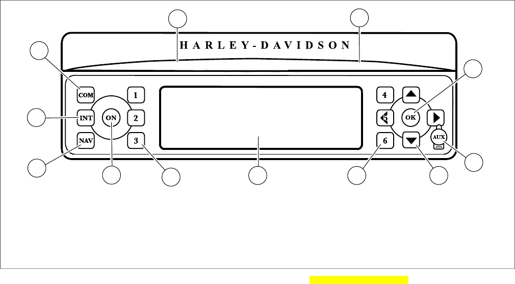
FRONT PANEL CONTROLS
hdtopic000532_1
See Figure 1.The front panel consists of a set of pushbuttons,
a liquid crystal display, (LCD), a protective door for the Compact
Disc (CD/MP3) slot and a covered input port for auxiliary (AUX)
players. Six of the pushbuttons are "soft keys" whose function
will change with the display.
ON
Press ON to turn the receiver on and off.
1, 2, 3, 4, 5/Left Arrow
For the stereo receiver, the soft keys, 1, 2, 3, 4, and 5/Left
Arrow, are used to store and then recall a selected radio fre-
quency (pre-sets). When combined with any of the Advanced
Audio System accessories, the function of any active soft key
for that accessory will be displayed next to the soft key in the
LCD display.
6
Pressing the 6 soft key will return the display to the previous
menu. For CB and Intercom Setup, the function of the 6 soft
key will be displayed in the LCD next to the 6 soft key.
2006 Sound System 3
5/Left, Up, Down, Right Arrows
The 5/Left, Up, Down, and Right Arrow soft keys are used
for radio band frequency tuning, Bass and Treble mixing, Fader
and Volume. They are also used to scroll and highlight a
selection in a list. For an Advanced Audio System accessory
module, the arrow keys are active when arrows appear in the
display.
OK
With a menu or list item highlighted, press the OK pushbutton
to confirm the selection and initiate the function.
COM
Active on the FLHTCU or on motorcycles equipped the
Advanced Audio System CB accessory, COM is the Citizen
Band (CB) setup button. See 2006 SOUND SYSTEM, CB
Operation. Press the COM pushbutton to display the CB Setup
menu.
INT
Active only on the FLHTCUI, INT is the intercom setup button.
See 2006 SOUND SYSTEM, Intercom Operation. Press the
INT pushbutton to display the Intercom Setup menu.
NOTE
With the headsets/microphones plugged into the rider and/or
passenger intercom sockets, the intercom is voice activated
(VOX).
NAV
Active only with the Advanced Audio System accessory, NAV
is the GPS positioning and turn-to-turn navigation setup button.
Press the NAV pushbutton to display the navigational menu.
LCD
The liquid crystal display (LCD) displays the operational status
of the stereo receiver and that of any accessory.
CD Door
The CD door is a spring-loaded cover and will stay open when
exchanging CDs.
Close the CD door after loading or unloading a CD. To close
the door, push the door down until it latches.
EJECT
The CD EJECT button is found under the CD cover. Press the
EJECT pushbutton to eject the CD.
4 2006 Sound System
AUX
The auxiliary input port under the AUX cover connects the
receiver to an auxiliary device such as a cassette or MP3
player.
Use a 1/8 in. (3.5 millimeter) male to male extension cord to
plug the line out or headset out from the auxiliary device into
the AUX port. AUX appears in the LCD as a mode selectable
with the MODE SEL switch.
The user has control of Bass, Treble, Fader and Volume. if so
equipped, but all other player functions are performed with the
auxiliary device. Set the volume level of the AUX device to
normal or average.
NOTE
Close the protective cap whenever the AUX port is not in use.
2006 Sound System 5
11 10
4
12
1
7
2
5
96
8
3
om00505
7.1. Soft Keys (4, 5/Left Arrow, 6)Communications (CB) setup
2. 8.CD cover Liquid crystal display (LCD)
9.3. Soft keys (1, 2, 3)EJECT (under cover)
4. 10.OK (Confirm) ON key
11.5. GPS position and turn-to-turn navigation setupAuxiliary connector cover
6. 12.Left (5), Up, Right, Down Arrow Keys Intercom setup
Figure 1. Advanced Audio System Front Panel hdgraphic000604h.xml
6 2006 Sound System

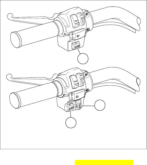
LEFT HANDLEBAR CONTROLS
hdtopic000533_1
See Figure 2. Easy to operate while riding, audio controls are
mounted on the left hand switch housing on the left handgrip.
For FLHX and FLHTC: The left hand audio control is an
+/AUDIO/- switch.
For FLHTCU and FLTR: The left hand audio controls are a
+/AUDIO/- and a PTT +/SQ/- switch. On FLTR models, the
PTT +/SQ/- switch is inactive.
+/AUDIO/- Switch
AUDIO: See Figure 2. Press the AUDIO: switch to access the
Audio/Setup menu on the LCD. Press and release AUDIO: or
the press the soft key to toggle to the next displayed function
in sequence from Bass, to Treble, to Fade, to Display, to
Volume and then to to AVC.
If the AUDIO switch is left on any selection the function auto-
matically reverts back to the selected mode after approximately
2-3 seconds.
+/-: Pressing the AUDIO switch upward (+) raises the level for
the currently selected Audio/Setup (Bass, Treble, Fade, Volume
or AVC). Pressing the switch downward (-) lowers the level.
The level is raised or lowered as long as the switch is held until
the minimum or maximum level is reached.
The LCD displays a horizontal dashed line to indicate the level.
In the center of the line is a single thin dash. When the level
is at the center, the selected audio is at a mid-point of its range.
The Fade function is only available on FLHTCU models. Fade
adjusts the balance between rider and passenger speakers.
Pressing AUDIO upward (+) moves the balance to the front
speakers while pressing AUDIO downward (-) moves the bal-
ance to the rear speakers. Equal volume in front and rear
speakers is indicated by one horizontal single line in the center
position.
The Display function sets the illumination level of the characters
in the LCD display.
The AVC (Automatic Volume Control) function sets the volume
level to compensate for the ambient noise associated with
motorcycle speed.
PTT and +/SQ/- Switch
See Figure 2. Push-To-Talk (PTT) and the squelch control
switch (+/SQ/-) is located on the left handlebar switch
assembly.
2006 Sound System 7
NOTE
The PTT and +/SQ/- is found on the FLHTCU Ultra Classic
and the FLTR Road Glide models. On the FLTR, this switch
is inoperative unless the optional CB, Hands-free phone
(Bluetooth) or GMRS accessory module is installed.
PTT: With the POWER on and the LCD indicating CB is active,
press and hold the PTT switch to transmit over the channel
displayed. Release PTT to end transmission.
+/SQ/-: Lower the threshold to allow reception of CB signals
by pressing the +/SQ/- switch toward the rear (-) or raise the
threshold by pressing the +/SQ/- switch toward the front (+).
1
2
1
om00511
1. +/AUDIO/-
2. PTT / +/SQ/-
Figure 2. LH Audio Controls: FLHTC/I, FLHX/I Upper -
FLHTCU/I, FLTRI Lower hdgraphic000616d.xml
8 2006 Sound System

RIGHT HANDLEBAR CONTROLS
hdtopic000534_1
See Figure 3.The mode select (MODE SEL) switch is located
on the right handlebar switch assembly.
UP/MODE SEL/DN Switch
MODE SEL
With the radio power ON, press and release the MODE SEL
switch to sequence between the radio bands.
When a audio CD/MP3 disc is inserted into the CD player the
CD function is added to the selections. When a 1/8 in. (3.5
mm) connector is plugged into the AUX input port the AUX
function is added to the selections.
The LCD display indicates the function selected.
UP/DN
In the receiver mode: UP/DN allows up or down radio station
SEEK tuning.
In CD/MP3 mode: UP/DN changes tracks and performs fast
advance and fast reverse.
In the CB mode: UP/DN changes the CB channel.
In the Intercom mode: UP/DN changes the voice activated
microphone (VOX) sensitivity.
In the AUX mode: The UP/DN switch is inactive.
For a detailed description of the various modes, see 2006
SOUND SYSTEM, Receiver Operation.
Table 1. Receiver Frequency Bands hdtable000378b.xml
STEPSFREQUENCYBANDMARKET
10 kHz530-1700 kHzAMDomestic
200 kHz87.75-107.9 MHzFM
25 kHz162.400-162.550 MHzWB
2006 Sound System 9

Table 1. Receiver Frequency Bands hdtable000378b.xml
STEPSFREQUENCYBANDMARKET
3 kHz144-279 kHzLWInternational
9 kHz531-1611 MHzMW
100 kHz87.5-108 MHzFM
9 kHz522-1629 MHzMWJapanese
100 kHz76.0-91.0 MHzFM
NOTE
The intercom and CB can be activated at the same time with
the receiver modes. The intercom and CB signals are passed
to the audio circuits only if the signal strength exceeds the
threshold established by CB squelch or VOX microphone
sensitivity levels. Depending on the position of the speaker
control switch in the fairing switch cap, the receiver function,
the CB, and the VOX microphone can be heard in the headsets
simultaneously. See 2006 SOUND SYSTEM, Intercom Opera-
tion and 2006 SOUND SYSTEM, CB Operation.
10 2006 Sound System
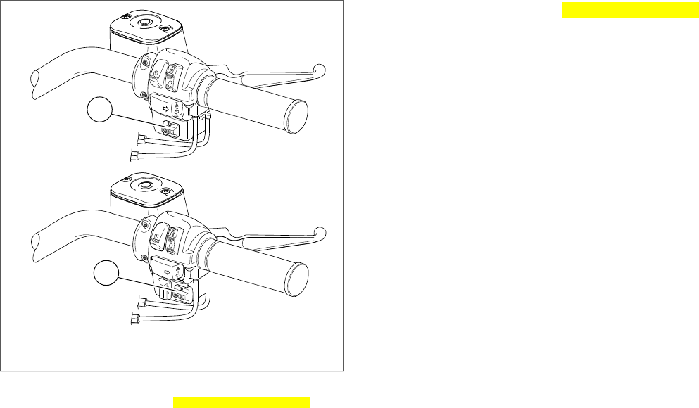
1
2
om00512
1. UP/MODE SEL/DN
2. UP/MODE SEL/DN
Figure 3. RH Audio Controls: FLHTC/I, FLHX Upper -
FLHTCUI, FLTRI Lower hdgraphic000617d.xml
RECEIVER OPERATION hdtopic000535_1
See Figure 1 for a picture of the stereo receiver front panel.
Set Time-of-Day
Set the time-of-day with the Ignition/headlamp Key Switch
turned to IGNITION or ACCESS but with the stereo receiver
OFF.
Press the Set soft key (6) (Set) on the front panel to display
the time setup menu.
See A in Figure 4. To increase the hours in the display press
the Hrs + soft key. To decease hours press the Hrs - soft key.
When the hour is correct, release the soft key.
To increase the minutes in the display press the Min + soft key.
To decease hours press the Min - soft key. When the minute
is correct, release the soft key.
Turn Receiver ON/OFF
To turn the receiver ON, turn the Ignition/headlamp Key Switch
to IGNITION or ACCESS and press the ON button on the front
panel. To turn the receiver OFF, press the ON button.
If the receiver is ON when the ignition is turned OFF, the
receiver will power up when the Ignition/headlamp Key Switch
is turned to IGNITION.
2006 Sound System 11
Select a Frequency Band
Using the right thumb, press the MODE SEL switch on the
right hand grip and release to cycle to the desired frequency
band (mode) or press the soft key next to the frequency band
displayed in the LCD to select a frequency band.
See B in Figure 4. The LCD highlights the selected band.
NOTE
See Table 1When a CD/MP3 disc is present in the CD slot
and/or an auxiliary player is plugged into the AUX port, the
MODE SEL switch will cycle through the CD and AUX modes
as well as the frequency bands.
Volume
See D in Figure 4. At any time the receiver is playing, the
volume can be adjusted by pressing the AUDIO switch up to
increase volume or down to decrease volume.
AM vs FM Reception
Commercial radio broadcasting is either AM (Amplitude Modu-
lation) or FM (Frequency Modulation).
AM
AM radio waves reflect off the ionosphere which results in
consistent signal reception at a long range (up to 100 miles or
160 kilometers).
However, AM radio can be displaced by loud humming, popping
and crackling noises. This is electrical interference caused by
noise from vehicle ignitions, electric signs, power lines and
electrical storms.
FM
The advantages of FM radio are high fidelity sound, stereo
reception, a wide range of broadcasting formats, and a signal
that is free of electrical interference.
The disadvantage of FM radio is its short range. FM radio
waves travel in straight lines, called "line-of-sight," therefore,
FM signals cannot be received over the horizon. At the limit of
a station's range, the reception may fade in and out when
objects pass between the transmitter and the motorcycle.
FM Stereo vs FM Mono
See E in Figure 4. Normally, the Harley-Davidson Integrated
Sound System plays FM signals in stereo.The LCD will indicate
STEREO.
12 2006 Sound System
However, the stereo receiver has circuits which eliminate or
minimize FM flutter due to weak stereo signals. The circuits
detect a weak FM stereo signal and automatically blend it into
a stronger FM mono signal.The transition is smooth and flutter
free because it occurs over a range of signal conditions, rather
than at a minimum threshold.
When the system is automatically blending or is receiving an
FM mono signal, the stereo indicator (STEREO) will disappear
from LCD screen.
WB
See G and H in Figure 4. Broadcast by the National Oceanic
and Atmospheric Administration (NOAA) National Weather
Band (WB) frequencies are available in North America only.
To receive NOAA weather alerts while listening to other radio
bands, highlight the Alerts indicator in the WB display by
pressing the soft key. An alert tone will automatically switch
the receiver to the announcing WB channel regarless of which
frequency band is playing.
When equipped with the CB module, use the soft key to high-
light the Alert indicator in the LCD display weather alerts are
announced over other audio and the Alert indicator is high-
lighted in the display.
Tuning-in a Radio Station
The radio has three tuning modes in each of the frequency
bands: Manual, Seek, Preset Scan and Scan.
Tuning in all three modes continuously wraps around the ends
of the band.
Manual Tuning
To manually tune the radio to a different frequency:
Press the Up Arrow button or the Down Arrow button to select
the frequency in that direction. Hold the selected arrow key,
and after a short delay of 1.5 seconds, the radio will continue
to change frequencies until the selected arrow key is released.
SEEK Tuning
See E in Figure 4. In SEEK, the radio tunes in to the next strong
station.
Press and release the MODE SEL switch up (UP) to tune in
the next strong station upward in the band. Press and release
the switch down (DN) to tune in the next strong station down-
ward in the band.
SCAN Tuning
In SCAN, the radio continuously tunes from one strong station
to the next until the SCAN is cancelled.
2006 Sound System 13
See F in Figure 4. Press and hold the MODE SEL switch UP
or DN approximately 5 seconds to scan the band for strong
station signals. Each strong station remains tuned in for 5 to
10 seconds before the radio scans to the next station. The
receiver will continue to scan until cancelled.
To select a station, cancel SCAN while the radio is tuned to
that station. Press the MODE SEL switch UP or DN to cancel
a SCAN moving up the band.
Preset Memory/Tuning
Use the soft keys, 1, 2, 3, 4, and 5/Left Arrow as preset but-
tons to store frequently tuned stations.
NOTE
See C in Figure 4. AM can store 5 preset frequencies.
See E and F in Figure 4. Separate FM1 and FM2 bands allow
the rider to store 2 sets of 5 preset FM frequencies (10 total).
Use the More soft key to toggle between FM1 and FM2. The
full range of FM frequencies can be selected in either FM1 or
FM2.
To store a current station, press and hold any one of the preset
buttons for 1.5 seconds. After an audible signal (a chirp), the
station's frequency has been stored and will the frequency will
appear in the display next to the preset soft key.
To tune to a stored station, press and release the preset soft
key.
PRESET SCAN Tuning
In PRESET SCAN, the radio continuously tunes from one
preset station to the next until the PRESET SCAN is cancelled.
A PSCAN icon will display while PRESET SCAN is active.
In the FM band, press and hold the More soft key for approx-
imately 3 seconds. Each preset station remains tuned in for
10 seconds before the radio moves to the next station.
To select a station, cancel SCAN while the radio is tuned to
that station. Press the MODE SEL switch UP or DN to cancel
a SCAN moving down the band.
Adjusting Volume
Volume can be adjusted in any radio band.
Volume is adjusted with the AUDIO switch on the left hand
grip. Using left thumb, press the AUDIO switch up (+) to raise
the volume or down (-) to lower the volume.
See D in Figure 4. The LCD displays the word Volume and a
bar graph that changes length with the volume.
Press the MODE SEL UP or DN to cancel the Audio/Setup
display or wait 5 seconds after the AUDIO switch is released,
the display switches to the currently selected frequency band.
14 2006 Sound System
See K in Figure 4.Volume can also be adjusted in Audio/Setup.
Use the MODE SEL switch to cycle to Volume and the AUDIO
switch to raise (+) or lower (-) the volume.
Mixing Bass and Treble
Bass and treble range adjustments can be applied to any
Integrated Sound System audio source.
BASS: See I in Figure 4. Press AUDIO to display Bass
Audio/Setup. Using the left thumb, press the AUDIO switch up
(+) to increase the bass range or down (-) to lower the bass
range.
The LCD displays the word Bass and a dashed line that
changes length with the setting.The thin center dash indicates
a middle setting.
TREBLE: See J in Figure 4. From Bass Audio/Setup, press
AUDIO to sequence to the Treble. Using the left thumb, press
the AUDIO switch up (+) to increase the treble range or down
(-) to lower the treble range.
See J in Figure 4. The LCD displays the word Treble and a
dashed line that changes length with the setting.The thin center
dash indicates a middle setting.
Adjusting AVC
See L in Figure 4. Automatic Volume Control (AVC) automat-
ically adjusts volume level to compensate for ambient noise
associated with motorcycle speed.
If the AVC does not adequately compensate for ambient noise
(or if it over compensates), enter the audio setup menu and
select AVC. Compensation is adjusted with the AUDIO switch
on the left hand grip. Using left thumb, press the AUDIO switch
up (+) to raise the compensation level or down (-) to lower the
compensation.
NOTE
Although the receiver AVC is preset at 3 bars, it is adjustable
from 0 bars (OFF) to 4 bars. At 1 bar, the volume does not
change with motorcycle speed. The more bars displayed, the
higher the volume increases with speed.
2006 Sound System 15
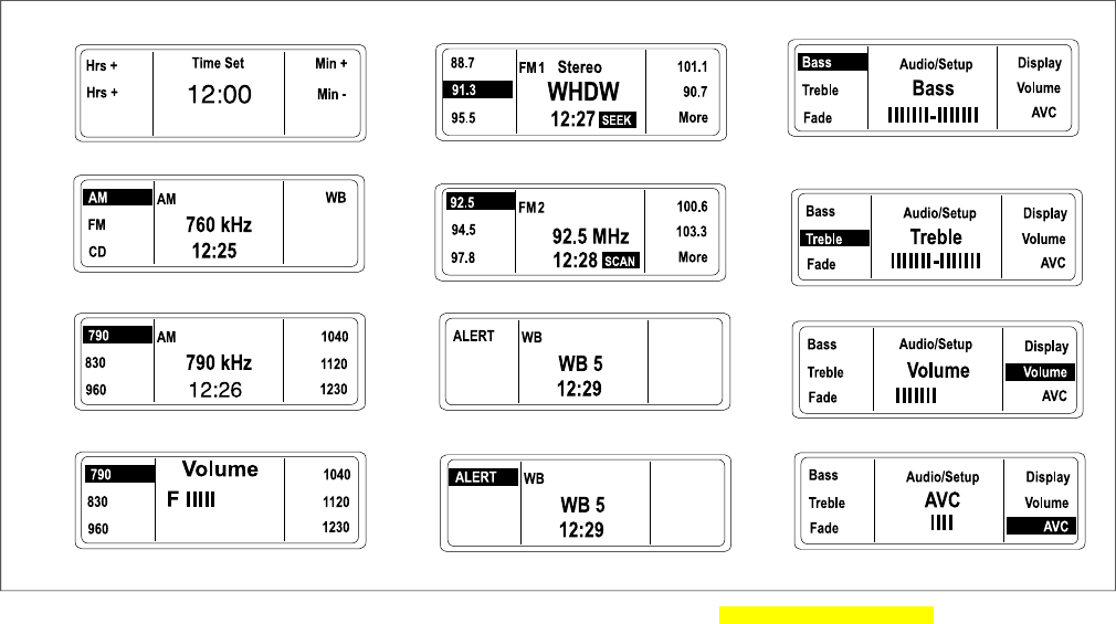
A
B
C
DH
K
E
F
G
L
J
I
om00501
Figure 4. FLHX, FLHTC and FLTR LCD Display Examples hdgraphic000634d.xml
16 2006 Sound System
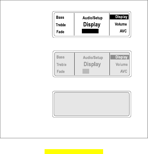
Adjusting Display Contrast
See Figure 5. Select Display from the Audio/Setup menu with
the AUDIO switch. Press the AUDIO up (+) to increase or down
(-) to decrease the contrast of the characters in the display.
NOTE
The contrast can be decreased to render the characters invis-
ible against the background.The characters will appear to have
disappeared in the display. Before leaving the Display screen,
always increase the character illumination to make the charac-
ters visible in other modes.
om00516
Figure 5. Character Display Illumination
hdgraphic000714c.xml
2006 Sound System 17

CD/MP3 OPERATION hdtopic000537_1
The CD player will accept commercial audio discs as well as
compact discs recorded with MP3 (MPEG 2.5 Level III), files
on compact disc read only (CDR) or compact disc read and
write (CDRW) formats.
There are no serviceable parts inside the unit; leave all
servicing to qualified service personnel. Disassembly of
the unit could result in equipment damage and/or equip-
ment malfunction. (00172a)
Do not change compact discs while riding, and do not
select a volume level that blocks out traffic noise. Distrac-
tions or a volume level that blocks out traffic noise, could
cause loss of control resulting in death or serious injury.
(00086a)
Do not disassemble unit. Laser radiation is present if disc
player is disassembled and the interlock fails or is
defeated. Exposure to laser radiation could lead to death
or serious injury. (00087a)
Auto Load
With the receiver power ON, raise the CD door and gently
insert a CD, label side up, into the CD slot until the unit auto-
matically pulls the CD into the player. Close the CD door.
See C in Figure 6.The receiver will automatically switch to CD
operation. The CD track number and play time will appear in
the LCD display. With a CD in the player, CD is added to the
modes selectable with the MODE SEL switch.
Set intercom volume level and other controls before riding
to minimize adjustments on the road. Distractions can lead
to loss of control, resulting in death or serious injury.
(00088a)
18 2006 Sound System

Disc Error 1
See B in Figure 6. If the CD loaded into the CD player is dam-
aged, of incorrect format, or if upside down, the LCD will display
the Disc Error 1 message.
Eject the CD. Refer to 2006 SOUND SYSTEM, Recommenda-
tions for Handling CDs.
Eject
Do not change compact discs while riding, and do not
select a volume level that blocks out traffic noise. Distrac-
tions or a volume level that blocks out traffic noise, could
cause loss of control resulting in death or serious injury.
(00086a)
Press the EJECT button found under the CD door to eject a
CD. The CD will be partially ejected. Remove the CD. Close
and latch the CD door.
The receiver will automatically return to the radio band and
frequency playing when the CD was loaded and the CD mode
is no longer selectable.
Tracks
To change CD/MP3 tracks, use the right thumb and press and
release the MODE SEL switch on the right hand grip. Press
UP and release to select higher numbered tracks or press DN
and release to select lower number tracks.
Pressing the Up Arrow and Down Arrow keys will also
advance tracks.
NOTE
The player automatically numbers the MP3 files found on a
CD in alphabetical order.
NOTE
If the MODE SEL switch is pressed and held UP or DN longer
than 1.5 seconds, the track selections will fast advance or
reverse as long as the switch is held.
CD track selection wraps around the first and last track.
Fast Advance and Reverse
To fast advance a track, press the MODE SEL switch UP and
hold longer than 1.5 seconds. The current track will fast
advance while the switch is pressed UP.The audio will advance
to the subsequent track as long as the switch is held UP.
2006 Sound System 19
See D in Figure 6. The play time display in the LCD will also
fast advance.
To fast reverse a track, press MODE SEL DN and hold longer
than 1.5 seconds. The current track will fast reverse while the
switch is pressed DN.
The play time display in the LCD will also fast reverse.
Random
To play tracks randomly, press the Random soft key on the
front panel while in the CD mode.The word Random will remain
highlighted in the display. No selection is repeated until all
other selections have been played.
NOTE
The Random soft key toggles between normal and Random
play. Press once for random play. Press a second time to return
to normal play. Pressing the MODE SEL switch UP or DNwill
select different tracks at random.
See D in Figure 6. Random will be highlighted in the display.
Scan
To scan the tracks on an CD/MP3 disk, press the Scan soft
key.
NOTE
The tracks will play for 8 seconds and then jump to the next
track which will play for 8 seconds.
Upon selecting a track, press and release the MODE SEL
switch to continue playing that track.
Repeat
To repeat a CD track while it is playing, press the soft key next
to the Repeat display.
To cancel Repeat, press the Repeat soft key again or press
the MODE SEL switch UP or DN to change tracks.
Repeat will no longer be highlighted in the display.
MP3
The receiver CD player will automatically recognize and play
MP3 files.
NOTE
The files will be numbered sequentially.
20 2006 Sound System
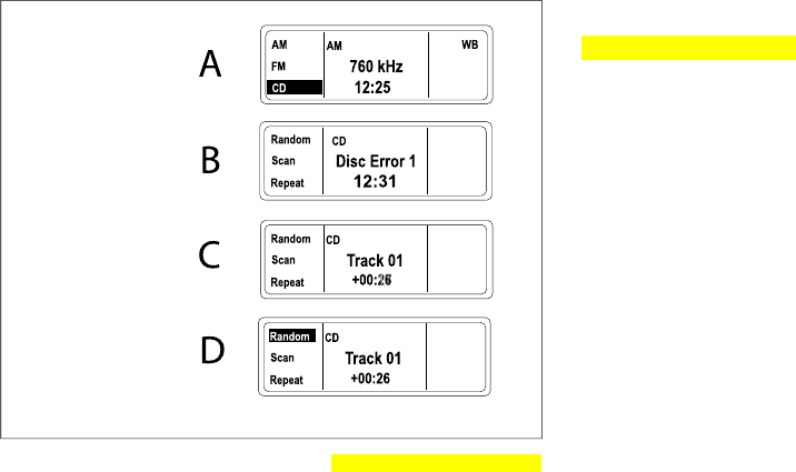
om00513
Figure 6. CD/MP3 Display Examples hdgraphic000715d.xml
RECOMMENDATIONS FOR HANDLING CDS
hdtopic000375_1
•Use caution when handling a CD. Avoid touching the
bottom (shiny) side.
•Store audio CD/MP3 discs in acrylic jewel cases to protect
against dust, scratches, light, and changes in humidity.
• Store CDs in a cool dry place away from direct sunlight.
•Store NAV discs in the original cases to protect against
dust, scratches, light, and changes in humidity. While
CD/MP3 discs are played through compensating software
which reduces the effects of scratches and dust, NAV
discs are data discs. A scratch will cause the Navigation
module to miss data and give incorrect navigation direc-
tions.
•Use commercially available cleaning tissue to clean the
CDs. Never use solvents that can damage the CD.
• Keep protective CD door closed at all times.
2006 Sound System 21

Do not disassemble unit. Laser radiation is present if disc
player is disassembled and the interlock fails or is
defeated. Exposure to laser radiation could lead to death
or serious injury. (00087a)
NOTE
A laser that cannot focus properly may cause skipping. A
clouded lens can be caused by dirty CDs, dust, smoke, high
humidity, and airborne particles may cause the laser lens to
cloud. Operating the CD without allowing the motorcycle to
warm up can also cause a CD to skip.
INTERCOM AND CITIZEN BAND WITH
PASSENGER SPEAKERS hdtopic000538_1
The FLHTCU supports includes a digitally tuned 40 channel
Citizen Band (CB) transceiver, a rider/passenger intercom.
Features include:
• Rider headset connector on fuel tank console.
• Passenger headset connector on backrest.
•Handlebar mounted rider push to talk (PTT/+/SQ/-) switch
(CB and Intercom).
• Fairing-mounted speaker switch.
•Rear-mounted passenger UP/MODE SEL/DN and
PTT/+/VOL/- switches (CB and Intercom).
• Digitally adjustable rear headset speaker volume.
•Passenger receiver band switching and frequency tuning.
• Passenger CD/MP3 player control.
•Rider hand-held microphone compatibility for areas that
prohibit headset (helmet-mounted) speakers.
22 2006 Sound System

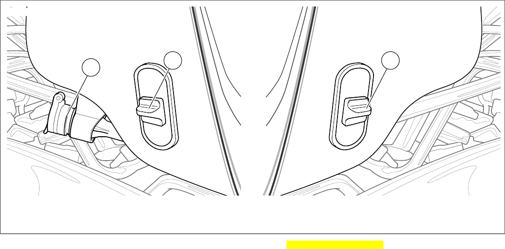
HEADSETS AND SOCKETS
hdtopic000551_1
Some local governments prohibit or restrict the use of
headset (helmet-mounted) speakers. Please check with
local authorities and obey all applicable laws and regula-
tions. (00173a)
A Harley-Davidson dealer can help you select the correct
genuine Harley-Davidson headsets and microphones for your
year and model Harley-Davidson. Harley-Davidson stereo
helmet headsets with 7 pin DIN jacks fit the rider and the pas-
senger intercom sockets found on the FLHTCU. Other headset
microphones will not work.
Open the socket cap and with the ridge on the headset jack
facing upward insert the jack into either the front or rear headset
socket.
NOTE
For areas that do not permit headset speakers, a special hand-
held microphone can be used to transmit over the CB. This
microphone is also available through a Harley-Davidson dealer.
Do not pull on the cord to remove the headset from the
socket. Pull on the headset jack to disconnect the headset
from the socket. (00174a)
The spring loaded hinge keeps the headset socket cap closed
while riding. It protects against dirt and water when the headset
or hand-held microphone is not in use. Before washing the
motorcycle, verify that BOTH rider and passenger socket caps
are closed.
2006 Sound System 23
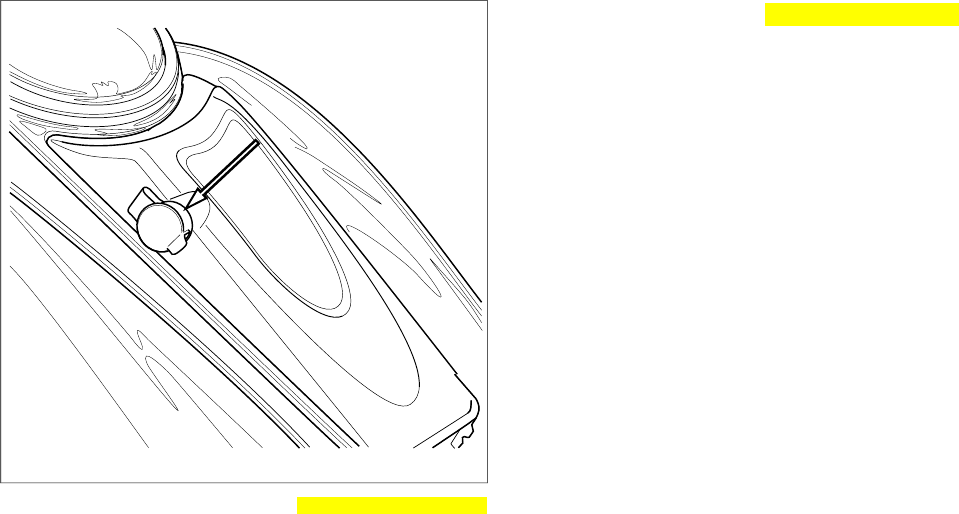
om00304
Figure 7. Front Headset Socket Cap hdgraphic000335c.xml
VOX MICROPHONES hdtopic000552_1
The Harley-Davidson intercom uses a voice-activated (VOX)
microphone for hands-free intercom operation. The headset
microphone minimizes the transmission of hand-held micro-
phone generated noise.
The intercom is activated when a voice or sound exceeds a
preset audio level, the voice is said to "break VOX". The voice
or sound is transmitted to the headsets.
NOTE
Pressing and holding the PTT switch will also open the micro-
phone.
Once VOX is broken, a conversation can proceed uninter-
rupted. After the absence of sound or voice, there is a delay
of approximately 2 seconds before the microphone is deactiv-
ated.This delay in deactivation allows for pauses in conversa-
tion.
Because loud exhausts, passing trucks, car horns or other
background sounds may unintentionally activate the intercom,
the sound level necessary to break VOX is adjustable. See
2006 SOUND SYSTEM, Intercom Operation.
24 2006 Sound System
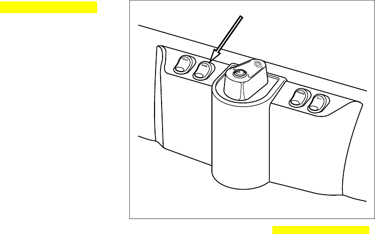
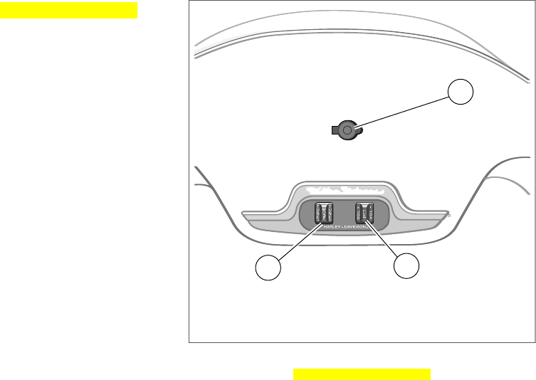
SPEAKER CONTROLS hdtopic000553_1
SPKR Switch
A three position speaker (SPKR) switch is located on the inner
fairing cap of the FLHTCUI and the FLTRI. See Figure 6.
NOTE
The SPKR switch found on the FLTR is inoperable.
Off/Forward: In the forward position, the speakers are off.
Audio (radio, CD/MP3, AUX and CB) is played in the headsets
only. During simultaneous CB reception, the other audio source
is muted and only the CB is heard in the headsets.
Center: In the center position, the radio, CD/MP3 player or
AUX is played over the speakers while the CB is played only
in the headsets.
On/Rearward: In the rearward position, the speakers are on.
With the SPKR indicator lit, the radio, the CD/MP3 player, or
any AUX device and the CB are played through both the rider
and passenger speakers.When a CB signal is received, other
audio sources mute and the CB is played over the speakers.
Refer to Table 4.
NOTE
The intercom is only heard in the headsets, regardless of the
SPKR switch position.
®
om00520
Figure 8. FLHTCU SPKR Switch hdgraphic000716c.xml
Rider to Passenger Speaker Balance
The receiver FADER control balances the front rider and rear
passenger speakers.
2006 Sound System 25

NOTE
FADER is available only on the FLHTCU equipped with rider
front and passenger rear speakers.
FADER: With the fairing speaker switch in either the SPKR or
center position, press the AUDIO switch to cycle through Bass
to Treble to Fade in the LCD. Or with the motorcycle stationary,
press the left hand AUDIO switch once to enter the Bass dis-
play and select Fade with the Mode Select switch or the soft
key.
The LCD displays the word Fader and a dashed line that
changes length left or right of a thin center dash.The thin center
dash represents equal balance between rider and passenger
speakers. See B in Figure 6.
•Press the AUDIO switch up (+) to raise the volume from
the rider speakers while lowering the volume from the
passenger speakers.
•Press the AUDIO switch down (-) to raise the volume from
the passenger speakers while lowering the volume from
the rider speakers.
PASSENGER CONTROLS hdtopic000539_1
UP/MODE SEL/DN Switch
See Figure 9. The passenger MODE SEL switch gives the
passenger control of radio band selection, tuning, CD/MP3
operation and all functions of the hand grip mounted MODE
SEL switch.
NOTE
For information on routing audio signals to the passenger
speakers and headsets, refer to Table 4.
PTT and +/VOL/- Switch
See Figure 9. The PTT/+/VOL/- switch on the right side of
speaker box allows the passenger to talk over the intercom or
transmit over the CB as well as to raise or lower the rear
headset volume.
See F in Figure 11.When the rear headset volume is adjusted,
a F (front) and R (rear) bar graph appear in the LCD display.
NOTES
•The passenger VOL switch affects only the passenger
headset. The hand grip mounted AUDIO switch is the
master volume control, and used in conjunction with the
26 2006 Sound System
FADER, affects both the rider and passenger speaker
volume.
•With stereo receiver tuning, radio band selection, CD/MP3
track selection or other functions, simultaneous use of
front and rear MODE SEL switches may cause operation
to be suspended until either rider or passenger controls
are released.
2006 Sound System 27
12 3
om00305
1. Passenger headset socket
2. UP/MODE SEL/DN
3. PTT/+/VOL/-
Figure 9. FLHTCU Passenger Controls hdgraphic000717d.xml
28 2006 Sound System
SIDECAR CONTROLS hdtopic000540_1
See Figure 10. A MODE/+/TUNE/- press and tilt switch, a
PTT/+/VOL/- press and tilt switch and a headset socket are
mounted on the dash of the TLE Ultra sidecar for the FLHTCUI.
These controls and stereo speakers of the sidecar are con-
nected to the Premium Sound System through a wire harness.
MODE and +/TUNE/- Switch
The MODE/+/TUNE/- switch controls radio band selection,
station tuning, and CD/MP3 track selection and operation.The
MODE/+/TUNE/- switch operates like the hand grip mounted
UP/MODE SEL/DN switch.
PTT/+/VOL/-
The PTT/+/VOL/- press and tilt switch controls the volume in
the sidecar speakers and is used to open the intercom and
transmit over the CB.
Pressing the PTT switch left (+) raises the volume level for the
currently selected Audio. Pressing the switch right (-) lowers
the volume level.
32
1
om00522
1. Headset socket
2. PTT/+/VOL/-
3. MODE SEL/+/TUNE/-
Figure 10.TLE Ultra Sidecar Audio Controls
hdgraphic000718c.xml
2006 Sound System 29

Table 2. Speaker Output Power hdtable000379c.xml
OHMS
PER
SPEAKER
SPEAKERSTOTAL
WATTS
MODEL
22 speakers,
20 watts each
40FLTRI
FLHTC
24 speakers,
20 watts each
80FLHTCU
22 speakers,
20 watts each
40TLE
Sidecar
w/amplifier
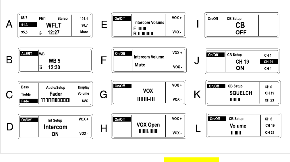
INTERCOM OPERATION hdtopic000541_1
Operation
To speak over the intercom, press and hold either rider or
passenger PTT switch to enable the microphones. Both
microphones are active while one or both PTT switches are
pressed.
NOTE
Always verify that the CB is off so that private intercom conver-
sations will not be transmitted.
Activating the Intercom and the VOX
Microphones
Press and hold the INT button on the front panel, to open the
Intercom Setup display.
See D in Figure 11. To activate the intercom (INT) and the
VOX microphones, press soft key 1 to turn the intercom ON.
The intercom will activate in Intercom Setup with VOX sensit-
ivity and headset volume level settings from the previous use.
VOX sensitivity and headset volume are adjusted in Int Setup
only.
To exit Int Setup, press and release the MODE SEL switch or
the INT button.
To make adjustments to VOX sensitivity after exiting Intercom
Setup, re-enter Intercom Setup by pressing INT.
NOTE
To ensure privacy, the intercom can only be heard through the
headsets.
To turn OFF the intercom and the VOX microphones, press
the INT button to open the Intercom Setup display and press
the On/Off soft key (1).
30 2006 Sound System

Adjusting VOX Sensitivity
VOX sensitivity should be adjusted so that the microphones
break VOX at a normal voice level.
Enter Intercom Seup by pressing the INT button. Press the ON
or 1 soft key to turn the intercom on.
See G in Figure 11. Press the MODE SEL switch UP or DN or
press the 4 or 5 soft key to initiate the VOX display. The LCD
displays VOX sensitivity as a bar graph. A higher number of
bars indicates greater sensitivity while a lower number means
less sensitivity.
Continue to use MODE SEL on the right hand grip to adjust
the sensitivity level. Press MODE SEL UP to make the micro-
phone more sensitive. Press the MODE SEL DN to reduce
sensitivity. To exit SETUP, press and release the MODE SEL
switch.
NOTES
•The receiver retains the sensitivity level from the previous
setup. However, if power is removed from the receiver,
VOX sensitivity defaults to mid level.
•VOX sensitivity may have to be adjusted if either micro-
phone is unintentionally activated because the microphone
misinterprets radio, road or background sound as conver-
sation.
When VOX is set to its maximum, the microphone is always
open. The VOX display will read Open.
When VOX is set to lowest value, the microphone is closed
and the VOX display reads Closed.
Adjusting Rider Headset Volume
The rider intercom volume is only adjustable in Intercom Setup.
See E in Figure 11. Enter Intercom Setup, speak into micro-
phone and adjust the intercom volume with the AUDIO switch
on the left hand grip. Press AUDIO + to raise the volume and
AUDIO - to lower the volume.The LCD displays a dashed line
that changes length with the level.
See F in Figure 11.When the headset volume has been adjust
to the bottom of its range, Mute will appear in the volume dis-
play.
To exit Intercom Setup, press and release the MODE SEL
switch.
Set intercom volume level and other controls before riding
to minimize adjustments on the road. Distractions can lead
to loss of control, resulting in death or serious injury.
(00088a)
2006 Sound System 31

Adjusting Passenger Headset Volume
The passenger intercom volume is only adjustable in Intercom
Setup.
Enter Intercom Setup. Speak into the microphone and adjust
the intercom volume with the AUDIO switch on the right
speaker box on the passenger's backrest. Press AUDIO + to
raise the volume and - to lower the volume. The LCD displays
a bar graph that changes length with the level.
See F in Figure 11.When the headset volume has been adjust
to the bottom of its range, Mute will appear in the volume dis-
play.
To exit Intercom Setup, press and release the MODE SEL
switch or press the INT pushbutton.
CB OPERATION hdtopic000542_1
Activating the CB
See H and I in Figure 11. To activate the Citizen Band trans-
ceiver, press and release the COM pushbutton on the front
panel. Press soft key 1 to turn the CB ON/OFF. The CB will
activate in CB Setup with squelch threshold and channel set-
tings from the previous use. CB channels are selected in CB
Setup.
To exit CB Setup but leave the receiver with the CB active,
press and release the MODE SEL switch or the COM push-
button.
To turn the off the CB, press the COM button to enter CB
Setup. Press soft key 1 to turn the CB ON and Off.
There are no adjustments internal to the CB transceiver
chassis that can be performed without risking non-compli-
ance with Federal Communications Commission (FCC)
rules. Refer to the original equipment manufacturer for
any service required during the warranty period. For
transmitter service after the warranty period, refer to a
certified repair service. Any frequency determining com-
ponents, such as crystals, or power determining semi-
conductors, etc., should only be replaced with the original
component manufacturer's part or equivalent. Substitutes
can result in violation of FCC rules. (00175a)
Entering CB Setup
See J in Figure 11. With the CB on, press COM to enter CB
Setup.The LCD displays CB SETUP in the upper half and the
CB channel appears in the lower half.
To exit CB Setup, press and release the MODE SEL switch.
32 2006 Sound System

After exiting CB Setup with the CB still active, re-enter CB
Setup by pressing and releasing the COM soft key.
Selecting a Channel
In CB Setup, use the MODE SEL switch to select a CB channel.
Press and release MODE SEL UP or DN to switch channels
one at a time.
Soft keys 4, 5 and 6 can be used to preset CB channels.
If the MODE SEL switch is held up or down, tuning continuously
wraps around the ends of the channels.
See K in Figure 11. When squelch is broken, the CB in the
display inverts. If the squelch is not broken and the another
source is playing, CB is displayed.
Set CB channel, squelch threshold and volume before
riding to minimize adjustments on the road. Distractions
can lead to loss of control, resulting in death or serious
injury. (00089a)
Adjusting Squelch
See K in Figure 11. The CB signal is passed to the speakers
or headsets only if signal strength exceeds the threshold set
with the squelch control switch (PTT/+/SQ/-).When CB signals
exceed the threshold, they are said to "break squelch." Refer
to Table 3.
•To lower the threshold to process the weakest CB signals,
press SQ - or rearward.
•To raise the threshold to process stronger signals, press
SQ + or forward.
In the LCD, a dashed line changes length with the setting.
Table 3. Squelch Control Switch hdtable000163b.xml
SQ (+) FORWARDSQ (-) REARWARD
Fewer signalsMore signals
Less noiseMore noise
Less staticMore static
Better sound qualityUnwanted signals
Transmitting
To transmit, press and hold the PTT switch. Transmission is
over the CB channel displayed in the LCD. To end transmis-
sion, release PTT.
2006 Sound System 33

Adjusting Volume
Refer to Table 3. See L in Figure 11. To adjust volume of the
CB in the speakers or headset, Press AUDIO + to raise the
volume or -lower the volume. CB volume is adjustable when
squelch is broken or when the dispaly is in CB Setup.
A dashed line that changes length with the volume setting is
displayed.
Operating the CB radio without an antenna or with a broken
antenna cable can result in damage to the transmitter cir-
cuitry. (00176a)
CB Range
Maximum transmission range can only be expected under
stable weather conditions in flat, open country.
Weather: In times of atmospheric disturbances, such as rain,
snow, or even sunspots, the CBs range can be reduced.
Terrain: Buildings, hills, valleys or any elevated objects or
depressions that either block or create a longer path between
transmitter and receiver will reduce or disrupt communications.
Obstructions: Transmissions may be cut off under a viaduct
or inside a tunnel or parking garage.
NOTE
The CB transmitter is the most powerful allowed under Federal
law, but since there is no large steel area to create a ground
plane, it may not transmit as strongly as when mounted in a
car or truck.
34 2006 Sound System
om00518
Figure 11. FLHTCU Display Examples hdgraphic000712d.xml
2006 Sound System 35

AUDIO ROUTING AND MIXING
hdtopic000554_1
General
Refer to Table 4. Whether audio is routed to the headsets,
speakers or both depends on the SPKR control switch and the
INT and CB buttons on the receiver.
A single audio source routed to headset or speaker can be
controlled with the riders AUDIO switch or the passenger VOL
switch.
NOTE
The passenger volume control switch affects only the pas-
senger headset.The handlebar mounted AUDIO switch is the
master volume control, and used in conjunction with the fader,
affects both the rider and passenger speaker volume.
Table 4. Audio Routing and Mixing Combinations hdtable000164c.xml
VOLUME CONTROLAUDIO ROUTING COMBINATIONS
AUDIO +/- OR VOL +/-AUDIO OUTAUDIO
SOURCE(S)
SPEAKER
CONTROL
SWITCH
Music*HeadsetsMusic*Off or Forward
(Headsets) CB (During reception or SETUP)HeadsetsCB
Intercom (Only in SETUP)HeadsetsIntercom
MusicBoth in the headsetsIntercom and music*
CB (During reception or SETUP)CB in the headsetsCB and music* (Music is muted during CB reception)
CB (During reception or Setup)Both in the headsetsIntercom and CB (Music is muted during CB reception)
36 2006 Sound System

Table 4. Audio Routing and Mixing Combinations hdtable000164c.xml
VOLUME CONTROLAUDIO ROUTING COMBINATIONS
AUDIO +/- OR VOL +/-AUDIO OUTAUDIO
SOURCE(S)
SPEAKER
CONTROL
SWITCH
Music*SpeakersMusic*Center
(Speakers and
headsets) CB (During reception or SETUP)HeadsetsCB
Intercom (Only in SETUP)HeadsetsIntercom
Music*Intercom in the headsetsIntercom and music* Music* in the speakers
CBCB in the headsetsCB and music* Music* in the speakers
Music is muted during CB recption
CB*Both in the headsetsIntercom and CB (Music is MUTED during CB reception)
2006 Sound System 37

Table 4. Audio Routing and Mixing Combinations hdtable000164c.xml
VOLUME CONTROLAUDIO ROUTING COMBINATIONS
AUDIO +/- OR VOL +/-AUDIO OUTAUDIO
SOURCE(S)
SPEAKER
CONTROL
SWITCH
Music*SpeakersMusic*On or rearward
(Speakers) CB (During reception or SETUP)SpeakersCB
Intercom (Only in SETUP)HeadsetsIntercom
MusicIntercom in the headsets.Intercom and music* Music in the speakers.
CBCB in the speakersCB and music* (When squelch is broken)
CBIntercom in the headsetsIntercom and CB (CB in the speakers MUTED during CB
reception)
* Music = Radio, CD player or auxiliary (AUX) audio source.
38 2006 Sound System

TROUBLESHOOTING hdtopic000555_1
Operational Troubleshooting
Refer to Table 5. Use the following table to identify rider or
passenger control settings that prevent intended operation.
NOTE
See the Touring Models ELECTRICAL DIAGNOSTIC MANUAL
for all system diagnosis and electrical troubleshooting informa-
tion.
There are no serviceable parts inside the unit; leave all
servicing to qualified service personnel. Disassembly of
the unit could result in equipment damage and/or equip-
ment malfunction. (00172a)
Do not disassemble unit. Laser radiation is present if disc
player is disassembled and the interlock fails or is
defeated. Exposure to laser radiation could lead to death
or serious injury. (00087a)
Radio Fuses
If it is necessary to replace the radio fuses, follow the fuse
replacement procedures in this manual or see your Harley-
Davidson dealer for service.
See Figure 12. Radio fuses are located in the fuse block under
the left side cover.
•The 10 amp fuse allows power to the radio through activ-
ation of an internal relay.
•The 15 amp fuse provides direct and continuous power
to the radio memory and time-of-day clock, and when the
internal relay is activated, feeds the main circuits of the
radio as well.
Remove the radio fuses and inspect the element. Replace the
fuse if the element is burned or broken. Automotive type ATO
fuses are used.
NOTE
See Figure 12. Spare fuses (10 amp and 15 amp) can be found
in the fuse block cover.
2006 Sound System 39
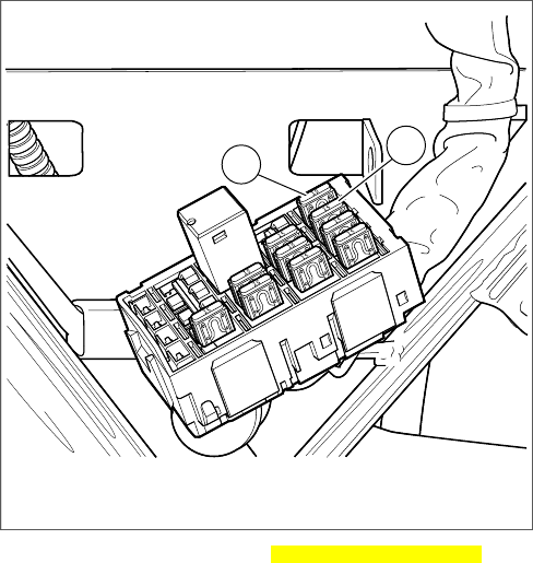
12
om00527
1. Radio power (10 Amp)
2. Radio memory (15 Amp)
Figure 12. Radio Fuses hdgraphic000721c.xml
40 2006 Sound System

Table 5. Operational Troubleshooting: Advanced Audio System hdtable000165e.xml
CAN PREVENT THISTHIS
Fairing musicSquelch broken
Headset music
Passenger speaker music
CB audioSquelch unbroken
CB audioCB off or low volume
Fairing musicFront or rear PTT on
Headset music
Passenger speaker music
CB audio
Fairing musicHandlebar volume low
Headset music
Passenger speaker music
Passenger headset music and CB audioPassenger headset volume low
Headset music and headset CB audioFairing SPKR back to speaker
Fairing music and CB audioFairing SPKR forward to headset
Voice communications (Unless PTT is pressed)INT off
2006 Sound System 41
42 2006 Sound System
NOTES

A
Advanced Audio System
Accessories..................................1
Audio Routing and Mixing......................36
CB Operation................................32
CB Transceiver..............................22
Description..................................1
Fader Control................................25
Fairing Controls..............................25
Front Panel Controls...........................3
Handling CDs...............................21
Headsets and Sockets.........................23
Intercom....................................22
Intercom Operation...........................30
Left Handlebar Controls.........................7
Passenger Controls...........................26
Passenger Speakers..........................22
Receiver Features.............................2
Receiver Operation...........................11
Rider to Passenger Speaker Balance.............25
Right Handlebar Controls.......................9
Sidecar Controls.............................29
Troubleshooting..............................39
VOX Microphones............................24
Audio Routing and Mixing
General....................................36
C
CB Operation
Activating the CB.............................32
Adjusting Squelch............................33
Adjusting Volume.............................34
CB Range..................................34
Entering SETUP.............................32
Selecting a Channel..........................33
Transmitting.................................33
CB Transceiver..................................22
CD Operation
Auto Load..................................18
CD Eject...................................19
Disc Error 1.................................19
Fast Advance and Reverse.....................19
MP3.......................................20
Random....................................20
Repeat.....................................20
Scan......................................20
Tracks.....................................19
F
Fader..........................................25
Fairing Controls
SPKR Switch................................25
Front Panel Controls
AUX........................................5
CD/MP3 Door................................4
a
INDEX
CD/MP3 EJECT...............................4
COM.......................................4
INT.........................................4
LCD........................................4
Left, Up, Down, Right Arrows....................4
NAV........................................4
OK.........................................4
ON.........................................3
Soft Key 1, 2, 3, 4, 5...........................3
Soft Key 6...................................3
Fuses.........................................39
H
Handling CDs
Audio CDs (MP3).............................21
NAV CDs...................................21
Headsets and Sockets............................23
I
Intercom.......................................22
Intercom Operation
Activating the Intercom........................30
Adjusting Passenger Headset Volume.............32
Adjusting Rider Headset Volume.................31
Adjusting VOX Sensitivity......................31
L
Left Handlebar Controls
+/AUDIO/- Switch.............................7
PTT and +/SQ/- Switch.........................7
M
MP3 (MPEG 2.5 Level III)..........................18
P
Passenger Controls
PTT and +/VOL/- Switch.......................26
UP/MODE SEL/DN Switch.....................26
Passenger Headset Volume........................32
Passenger Speakers..............................22
R
Receiver Operation
Adjusting AVC...............................15
Adjusting Volume.............................14
AM........................................12
AM vs FM Reception..........................12
AM vs FM Reception..........................12
Display Contrast.............................17
FM........................................12
FM Stereo vs FM Mono........................12
Mixing Bass and Treble........................15
b
Preset Memory/Tuning........................14
PRESET SCAN Tuning........................14
SCAN Tuning................................13
SEEK Tuning................................13
Selecting a Frequency Band....................12
Setting Time-of-Day...........................11
Tuning-in a Radio Station......................13
Turning Receiver ON/OFF......................11
WB........................................13
Rider to Passenger Speaker Balance.................25
Right Handlebar Controls
UP/MODE and SEL/DN Switch...................9
S
Sidecar Controls
MODE and +/TUNE/- Switch....................29
PTT/+/VOL/-................................29
SPKR Switch...................................25
T
Troubleshooting
Operational Troubleshooting....................39
Radio Fuses................................39
V
VOX Microphones................................24
c
d
NOTES

STRIP-IN LANGUAGE SPECIFIC
ALARM CARD FRONT HERE

STRIP-IN LANGUAGE SPECIFIC
ALARM CARD BACK HERE

VEHICLE V.I.N.: CRANKCASE NO.:
OWNER’S NAME:
OLD ADDRESS: APT. NO.:
CITY: STATE: ZIP CODE:
DEALER NUMBER: DELIVERY DATE:
DEALER’S NAME:
CITY: STATE: ZIP CODE:
MY NEW ADDRESS IS:
NEW ADDRESS: APT. NO.:
CITY: STATE: ZIP CODE:
MY MOTORCYCLE SOLD TO:
NEW OWNER’S NAME: DATE OF SALE:
ADDRESS: APT. NO.:
CITY: STATE: ZIP CODE:
Important Information
If you move from your present
address at any time after purchasing
your new Harley-Davidson or if you
sell it to anyone, please fill out the
attached card and mail immediately.
This will provide us with an accurate
registration as required by Federal
law.
Thank You!

Back of Reply card goes here