Midland Radio 917100B BASE STATION/REPEATER User Manual Base Tech III OPERATOR S MANUAL
Midland Radio Corporation BASE STATION/REPEATER Base Tech III OPERATOR S MANUAL
Users Manual
Operators Manual for the P25
Base Tech III Base/Repeater Station
October 2008
Version 5.0
680-090-2042
www.midlandradio.com

2
www.midlandradio.com
Introduction
We thank you for choosing the Midland P25 Base Tech III Base/Repeater Station to
meet your communication needs. Properly used, this product will give you many years
of reliable service. To get the most out of your purchase, be sure to carefully read this
manual before operating the radio.
The overall operation of this radio depends entirely on how it has been programmed. If it
is not functioning as desired, please check the programming first.
This manual covers up to firmware version 71BS241
If you should need Midland Technical Support, please call 1-816-462-0463 or
lmrservice@midlandradio.com
Other useful Midland numbers;
Main Line- 816-241-8500
Main Fax- 816-241-5713
LMR Sales- 816-462-0462
Credit Dept- 816-462-0464
Technical Support and Engineering Fax- 816-241-3272
Warranty Service- 816-462-0438
We welcome any comments on how we may improve our products to better server our
customers.
______________________________________________________________________________
WARNING: The antenna(s) used for this transmitter must be fixed-mounted on
outdoor permanent structures with a separation distance of at least 6 meters from all
persons during normal operation. The peak conducted output power at each antenna
terminal must not exceed 250 Watts and the peak radiated output power must not
exceed 1000 Watts EIPR. Users and installers must ensure that FCC requirements for
satisfying RF exposure compliance are met. (See FCC Rules Part 1, Sections 1307 and
1310)
NOTICE: The AMBE+2 ™ voice coding Technology embodied in this product is
protected by intellectual property rights including patent rights, copyrights and trade
secrets of Digital Voice Systems, Inc. This voice coding Technology is licensed solely
for use within this Communications Equipment. The user of this Technology is explicitly
prohibited from attempting to extract, remove, decompile, reverse engineer or
disassemble the Object Code, or in any other way convert the Object Code into a
human readable form. U.S. Patents Nos. #5,870,405, #5,826,222, #5,754,974
#5,701,390, #5,715,365, #5,649,050, #5,630,011, #5,581,656, #5,517,511, #5,491,772,
#5,247,579, #5,226,084 and #5,195,166.
Version 5.0
680-090-2042

3
www.midlandradio.com
Table of Contents
Page
1. LCD Display 4
2. LED Display 4
3. Key Controls 5
4. Programming 6
5. Control Knob 6
6. Channel Selection 7
7. P25 Calling Selection 8
8. P25 PTT Mode 9
9. P25 Conventional Messages 10
10. P25 Squelch Adjustment 16
11. Talk Group ID Alias 16
12. Key lock 17
13. Manual CWID Start/Stop 18
14. DTMF Encode 18
15. Analog Channel Data 19
16. P25 Channel Data 19
17. Bar Graph/Channel Display 20
18. LCD Backlight Toggle 20
19. Changing TX Power 21
20. Caller ID 21
21. Emergency Call Reception 22
22. Repeat Mode 22
23. Base Mode 23
24. Remote Control 23
25. P25 Test Mode 24
26. Adjustment Mode 26
27. Key Test 28
28. Displaying Firmware Version 29
29. Displaying Serial Number 29
30. Displaying Program Software Ver 30
31. Data Check 30
32. Error Messages 31
33. Firmware Error Detection 31
34. RS232 Error Detection 31
35. DSP Error Detection 32
36. Option Port Pinout 33
Version 5.0
680-090-2042

4
www.midlandradio.com
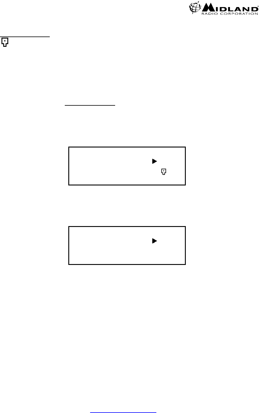
1. LCD DISPLAY
1.1 LCD display consists of 4 x 20 characters as shown.
Line 1: The Incoming RSSI with 10 steps
Line 2: The output power levels with 10 steps
Line 3: The left 4 letters show channel numbers. The middle 8 letters
shows the channel name (if not programmed, it will be blank).
The right 4 letters displays the status of the radio as described below.
a. RX mode: M= Mix, both analog and digital can be received
D= Only digital can be received.
b. TX mode: D=PTT digital transmission A=PTT analog transmission
c. Monitor mode: ⌧= Monitor off
S= Selective squelch
d. P-25 squelch: N= Normal squelch
S= Selective squelch
e. Low Voltage Icon: = Low Voltage state (Icon flashes with ALM LED)
f. Key lock mode: =Key lock (Not displayed if in Low Voltage alarm)
g. Shift mode: SHIFT KEY ICON (reverts to normal within 2 seconds)
Line 4: The left 2 letters show GPC (GROUP CALL), AC (ALL CALL),
IC (INDIVIDUAL CALL).
The right 18 letters displays the GROUP NAME, INDIVIDUAL
NUMBERS, ETC.
RX = = = = = = = = = =
TX = = = = = = = = = =
C001 TAC 2 MD⌧N
GPC 500
2. LED DISPLAY
The Midland Base Tech III has 5 LED's
From left to right;
DIGI= The LED is on when receiving a digital signal
REP= The LED is on when in repeat mode.
(The BASE TECH III can be programmed for,
SIMPLEX -SEMIDUPLEX - DUPLEX- REPEATER on a per channel basis.)
ALM= The LED flashes when an error on either TX or RX occurs
TX= The LED is on when in Transmit
BUSY= The LED is on when receiving a signal.
Version 5.0
680-090-2042

5
www.midlandradio.com
3. KEY CONTROLS
3.1 Key entry without SHIFT key
0-9: channel numbers and individual call address (target address)
A: P-25 calls (Group Call, All Call, and Individual Call)
B: The beginning and the end of individual call number
C: No function
D= P-25 mode (analog or digital TX)
*= Cancel channel number, individual number
#= Ending channel number, individual number
CH= Channel number entry, depress CH, then 0-9 for channels
F (Scan) = P25 Conventional Control Messages (SBC)
MON= monitor ON or OFF
Rotary knob: Volume, Squelch, Back Light Dimmer and Timer
3.2 Key entry following SHIFT key
0= P-25 test mode start and finish
1=back light ON/OFF
2=TX power Hi/LOW
3=Talkaround ON/OFF
4=No function
5=No function
6=No function
7=Indicates Analog channel data
8=Key lock ON/OFF
9=No function
A=Manual CWID send key
B=Programmed CWID Start/Stop key
C= No function
D= No function
*= Indicating P-25 data (while depressed)
#= DTMF Entry
CH= Toggle Bar-Graph or TX RX Frequencies
F (Scan) = SBC (Conventional Control Messages) Mode / Emergency Call
MON = P-25 squelch normal or selective and analog MONITOR modes.
Version 5.0
680-090-2042

4. PROGRAMMING
The Midland Base Tech III must be programmed with Windows 2000, XP or Vista
operating system.
The 91-1480CD software and 91-1303B programming cable are required to
program the radio and are available through your Midland dealer or LMR Sales
Department.
Note: During actual data transfer the radio will not operate but should be complete
within 30 seconds or less.
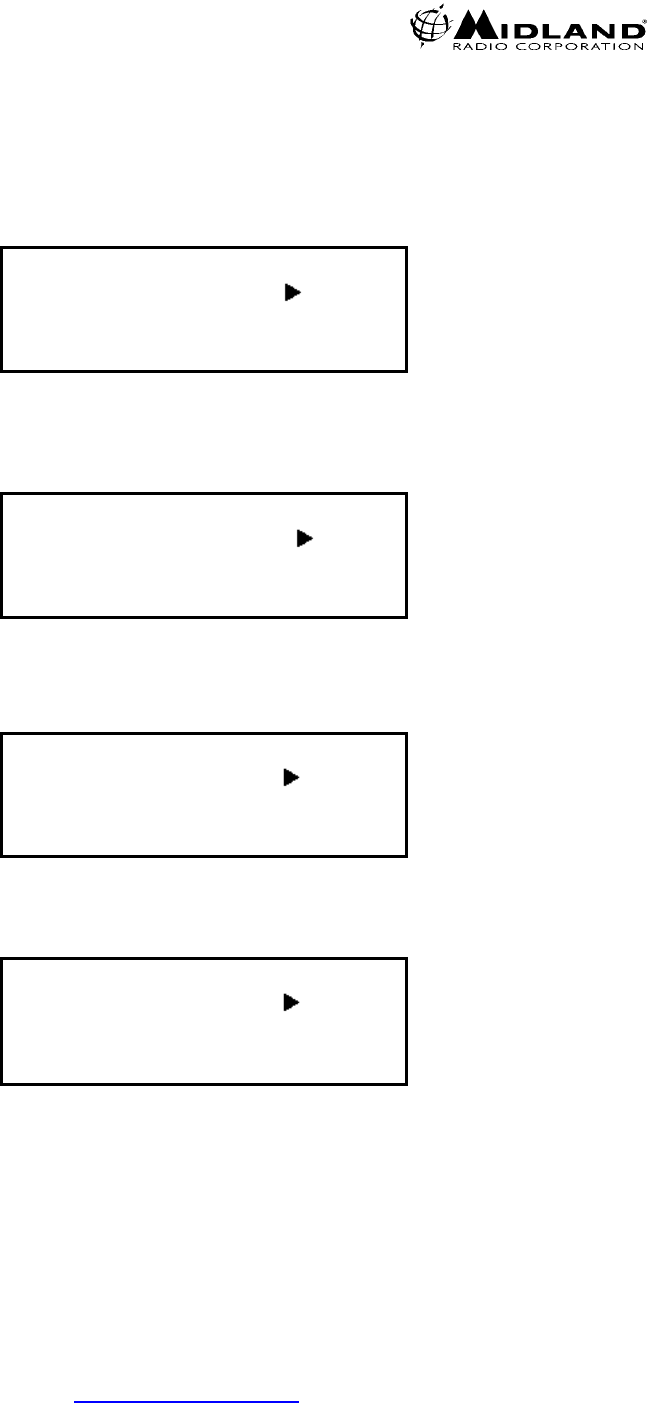
5. CONTROL KNOB
5.1 VOLUME
Rotate the knob to change the volume level.
The volume level varies from 0 to 34. If the local speaker is active, the audible beep
level will change as the knob is rotated.
Figure 3 shows the Volume at level 12
RX
TX
C001 TAC 2 MD⌧N
Volume-12
Figure 3
6
www.midlandradio.com
Version 5.0
680-090-2042

5.2 SQUELCH CONTROL
Push the rotary knob once to select the squelch level and then turn the knob to vary
the level from 0 to 15. 0 is open squelch.
Figure-4 shows the Squelch at level 6
RX
TX
C001 TAC 2 MD⌧N
Squelch-6
Figure 4
5.3 LCD BACKLIGHT DIMMER
Push the rotary knob twice to select the dimmer level and then turn the knob to
select a level from 0 to 15, 0 is the darkest.
Figure-5 shows the Dimmer at level 5
RX
TX
C001 TAC 2 MD⌧N
Dimmer-5
Figure 5
5.4 LCD BACKLIGHT TIMER
Push the rotary knob three times to adjust the Backlight Timer. The Time varies from
0 to 30 seconds. This function is inactive when the Backlight has been turned on
with SHIFT + 1 (Backlight ON/OFF).
Figure-6 shows the Backlight Timer set for 15 seconds
RX
TX
C001 TAC 2 MD⌧N
Light-15
Figure 6
6. CHANNEL SELECTION
The Midland Base Tech III has capability of up to 500 channels.
Press CH, and then enter the channel number.
Example-1 CH-8; Press CH + 0 + 0 + 8 or CH +8 + #
Example-2 CH-500; Press CH + 5 + 0 + 0
7
www.midlandradio.com
Version 5.0
680-090-2042

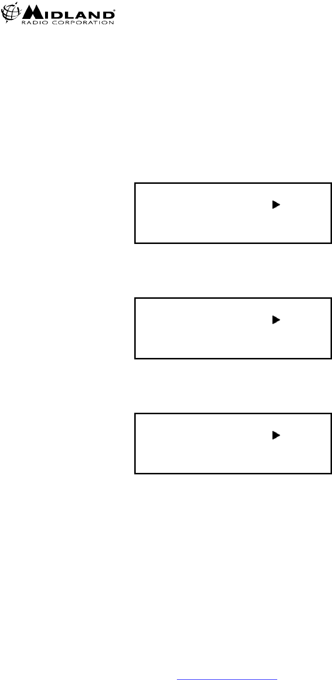
7. P-25 CALLING SELECTION (Digital Base Mode Only)
Press and release A repeatedly to scroll through the menu
Radio displays GPC 00001= Group 1 Call, GPC everygroup= All Call,
IDC--------- = Individual Call
Figure-7 Shows Talk Group Identification (TGID), Group 1 Call
Figure-8 shows an All Call (everygroup), to everygroup on the same NAC
Figure-9 Shows an Individual Call, to and individual unit ID on the same NAC.
(Refer to Section 11, Figure 11 and 12 for ID entry).
RX
TX
C001 TAC 2 MD⌧N
GPC 00001
Figure 7
RX
TX
C001 TAC 2 MD⌧N
GPC everygroup
Figure 8
RX
TX
C001 TAC 2 MD⌧N
IDC -------------------
Figure 9
8
www.midlandradio.com
Version 5.0
680-090-2042

7.1 INDIVIDUAL CALL ENTRY (Digital Base Mode Only)
Press and release A repeatedly until IDC----- is displayed.
Press B, and enter the numerical Unit ID.
To deleted a digit, Press the star ( * ) key
Press B or # to complete entry.
Figure-10 shows entry start, when B is pressed
Figure-11 shows completed entry, 1 + 2 + 3 + 4 + 5 + B
RX
TX
C001 TAC 2 MD⌧N
IDC __
Figure 10
RX
TX
C001 TAC 2 MD⌧N
IDC 12345
Figure 11
8. P-25 PTT MODE
Press D to select PTT (Push-To-Talk), mode.
When the display shows PTT is Analog, the radio
transmits in analog mode.
When the display shows PTT is Digital, the radio transmits in digital mode.
Figure-12 Shows Analog
Figure-13 Shows Digital
RX
TX
C001 TAC 2 MD⌧N
PTT is Analog
Figure 12
RX
TX
C001 TAC 2 MD⌧N
PTT is Digital
Figure 13
9
www.midlandradio.com
Version 5.0
680-090-2042

9. P25 CONVENTIONAL CONTROL SIGNALLING (SBC) (Digital Base Mode Only)
Please note: SBC functions are selectable in the Programming Software.
The Base Tech III has been developed to work with any P25 radio under the TIA
specifications. However not all subscriber radios have the capability of these
functions.
9.1 EMERGENCY MODE TX-
Press and hold the F key to send an EMERGENCY call. (Note: The radio will
transmit on the programmed EMERGENCY channel not necessarily the channel
that appears on the display.)
Reboot the radio to clear the Emergency Alert.
EMERGENCY MODE RX-
To clear a received Emergency call, Press and release F twice.
Press F to enter the SBC mode.
Key functions after entering menu selection;
Press A for the next and B for the previous menu item.
C stops transmission (The radio transmits the SBC 4 times until acknowledged.)
D moves the cursor between items within the selection.
* deletes the last digit.
# transmits the selected SBC mode.
Please Note: When the radio is in SBC mode, it can receive Group calls, All Call and
Individual calls but no source address (caller unit ID), is displayed.
Emergency calls can be received when in SBC mode but the radio gives priority to
Radio Inhibit. Both Emergency and Radio Inhibit are ignored when in SBC
transmitting mode.
The radio will revert to normal operation if no key is pressed for 10 seconds.
10
www.midlandradio.com
Version 5.0
680-090-2042

9.2 CALL ALERT-
To send a Call Alert, Press F then Press A or B until the selection is displayed,
then enter the target ID of the radio to alert and Press #. If the target radio has
received the Call Alert the display should show “ACK” (acknowledgement).
Figure 14 displays a Call Alert ACK
Call Alert
To: 366
MD⌧N
Fm: 00000366 (ACK)
Figure 14
9.3 RADIO CHECK-
The dispatcher can send a message to a subscriber unit requesting a response from
the radio (for example, to check if it is in operation).
To initiate a Radio Check, Press F then Press A or B until the selection is
displayed, then enter the target ID of the radio to alert and Press #. If the target radio
has received the Call Alert the display should show “ACK” (acknowledgement).
Figure 15 shows Radio Check Display.
Radio Check
To:_
MD⌧N
Fm: 00000366 (ACK)
Figure 15
11
www.midlandradio.com
Version 5.0
680-090-2042

9.4 RADIO INHIBIT-
This function is used to disable a subscriber unit (Mobile or Portable). The
subscriber unit cannot be turned on at all until an Uninhibit Command is sent. The
password must match the password entered in the BTIII program for inhibit to occur.
To Inhibit a radio, Press F then Press A or B until the selection is displayed then
enter the target radio’s ID. Press D and enter the programmed password, then
Press #. The target radio will be totally disabled. If the target radio has received the
Call Alert the display should show “ACK” (acknowledgement).
Figure 16 shows the Radio Inhibit entry display.
Radio Inhibit
To:_
Password: MD⌧N
Figure 16
9.5 RADIO UNINHIBIT-
Used to enable a subscriber unit that has been disabled, the password must match
the password entered in the BTIII program.
To Uninhibit a radio, Press F then Press A or B until the selection is displayed and
enter the target radio’s ID, enter the password and then Press #. The target radio will
be returned to normal operation. The target radio should send an ACK if successful.
Figure 17 shows the Radio Uninhibit entry mode.
Radio Uninhibit
To:_
Password: MD⌧N
Figure 17
12
www.midlandradio.com
Version 5.0
680-090-2042

9.6 STATUS UPDATE-
Used to send user status. The status numbers relates to an actual message list.
Indicates the User status (0-255) and Unit status (0-255).
To send a Status Update, Press F then Press A or B until the selection is displayed
and enter the target radio ID. Then Press D and enter the User (USR), message
number, Press D again and enter the Unit number, then Press #. If the target radio
has received the Call Alert the display should show “ACK” (acknowledgement).
Figure 18 shows Status Update ready to be sent to 366.
Status Update
To:366
USR : 1 UNT : 0 MD⌧N
Figure 18
9.7 STATUS REQUEST-
Is used to request the status of another unit. After the request is sent the target unit
should respond with the current status. In the example below USR: 2, means the
number 2 status message.
To send a Status Request, Press F then Press A or B until the selection is
displayed and enter the target radio ID then Press #. The target unit should respond
with the message number, unit ID and ACK.
Figure 19 shows Status Request received from 366.
Status Request
To:366
USR: 2 UNT: 0 MD⌧N
Fm: 00000366 (ACK)
Figure 19
13
www.midlandradio.com
Version 5.0
680-090-2042

9.9 PREDEFINED MESSAGES-
Is used to send a predefined system message.
To send a Predefined Message, Press F then Press A or B until the selection is
displayed, then enter the target radio ID, Press D and enter a message number and
Press #. The target radio should send and ACK if successful.
Figure 20 shows message 2 ready to be sent to 366.
Short Message
To:366
Message:2 MD⌧N
Figure 20
9.10 RADIO MONITOR-
Used to key up a target radio from 10 to 60 seconds and monitor the transmit audio.
To monitor a radio, Press F then Press A or B until the selection is displayed, then
enter the target radio ID, Press D and enter 1 (10sec),2 (30sec), or 3 (60sec).
Figure 21 shows Radio Monitor request to 366 to transmit for 30 seconds.
Radio Monitor
To:366
TX Multi:1 MD⌧N
Figure 21
14
www.midlandradio.com
Version 5.0
680-090-2042

9.11 TELEPHONE-
Used to initiate a telephone interconnect request on the RF subsystem.
Press F then Press A or B until the selection is displayed, then enter the complete
telephone number including country and area code. (max. 16 digits), then Press #.
Figure 22 shows the Midland Radio Corporation telephone number.
Telephone
To:18162418500
MD⌧N
Figure 22
9.12 SBC LOG-
To toggle the SBC LOG ON, Press SHIFT+F, to turn the LOG OFF Press F.
When the SBC LOG is entered, the last SBC call is displayed. Press B to scroll to
the previous records and Press A to scroll to the end of the list.
The radio will store up to 99 log entries. When more than 99 entries are made the
oldest log will be deleted.
Note: When the radio is reset or reprogrammed, all logs are deleted.
Figure 23 shows the fifth entry of the SBC Log.
< SBC Log >
5: To: 00000366 F
Radio Monitor
TX Multi: 3
Figure 23
15
www.midlandradio.com
Version 5.0
680-090-2042

10. P-25 SQUELCH ADJUSTMENT
Press SHIFT + MON to choose the P-25 squelch mode.
Normal SQL= If NAC is the same, the receiver will unmute
Selective SQL= If NAC and GROUP is the same, the receiver will unmute
Figure-24 Shows Normal SQ
Figure-25 Shows Selective SQ
RX
TX
C001 TAC 2 MD⌧N
Normal SQL
Figure 24
RX
TX
C001 TAC 2 MD⌧N
Selective SQL
Figure 25
11. TALKGROUP ALIAS ID
When GPC is selected with the “A” key, the TGID alias is indicated as programmed
(Max 8 characters)
Figure-26 shows POLICE for the TGID alias.
RX
TX
C001 TAC 2 MD⌧N
GPC POLICE
Figure 26
16
www.midlandradio.com
Version 5.0
680-090-2042
12. KEY-LOCK
Press SHIFT+8 to enable and disable the Key-lock. This symbol
shows on the LCD. Key-Lock and Key-Unlock icon is displayed
for 2 seconds and then reverts to show the TGID.
The PTT, MON and SHIFT key are not locked
If PTT, MON and SHIFT needs to be locked, select DISABLE in the
programming software. If the station is to be remotely controlled it is
recommended to leave PTT enabled, Remote PTT will not work when PTT is
locked.
To release key lock, Press SHIFT+ 8 again.
Figure-27 shows key locked
Figure-28 shows key unlocked
RX
TX
C001 TAC 2 MD⌧N
Key-Lock
Figure 27
RX
TX
C001 TAC 2 MD⌧N
Key-Unlock
Figure 28
17
www.midlandradio.com
Version 5.0
680-090-2042

13. MANUAL CWID START AND STOP
Press SHIFT + A to manually send the programmed CWID.
CAUTION: THE TRANSMITTER WILL ENERGIZE IMMEDIATELY WHEN “A” IS
PRESSED!
To turn OFF CWID, Press SHIFT + HOLD B for 2 seconds
(This disables both programmed and manual CWID)
To return to normal operation, either reboot the radio or
Press SHIFT+ HOLD B for 2 seconds
(CWID must be enabled in programming to use these functions).
Figure 29 shows CWID Sending
Figure 30 shows CWID function stop
Figure 31 shows CWID function start
CWID sending
Code: MIDLAND
C001 TAC 2 MD⌧N
Figure 29
RX
TX
C001 TAC 2 MD⌧N
CWID function stop
Figure 30
RX
TX
C001 TAC 2 MD⌧N
CWID function start
Figure 31
14. DTMF ENCODE
Press SHIFT + # and then enter 0-9, * or # to transmit DTMF.
The DTMF modulation level will be the same as the CWID level.
Figure 32 displays DTMF Encode mode.
DTMF Encode
123456
MD⌧N
Figure 32
18
www.midlandradio.com
Version 5.0
680-090-2042

15. ANALOG CHANNEL DATA
Press SHIFT+7 to scroll through the data. 7 must be depressed to scroll.
1) Rx width (narrow/wide/4kHz)
2) TX width (narrow/wide/4KHz)
3) Base mode (Simplex/Semi-duplex/Duplex/Repeater)
4) Rx CTCSS/DCS, CTCSS and DCS are used in Rx
5) TX CTCSS/DCS, CTCSS and DCS are used in TX
6) TX RX Modulation type either PM or FM (PM is the default)
(The INFORMATION DISPLAY selection in the 91-1480CD MISCELLANOUS MENU must be
set to ENABLE to display this information.)
Figure-33 Displays indicates a narrow channel during scroll.
RX
TX
C001 TAC 2 MD⌧N
RX Narrow Channel
Figure 33
16. P-25 CHANNEL DATA
Press SHIFT+ * to scroll through the data, * must be depressed to scroll.
1/ Unit ID (source address) 8/ Radio Inhibit RCV
2/ RX NAC 9/ Radio Un-inhibit RCV
3/ TX-NAC 10/ Status Update RCV
4/ TGID 11/ Status Request RCV
5/Emergency Alarm RCV 12/ Short Message RCV
6/Call Alert RCV 13/ Radio Monitor RCV
7/ Radio Check RCV
These functions may be enabled and disabled in the programming software’s
“MISCELLANEOUS/ INFORMATION DISPLAY” section.
Figure 34 Shows the Unit ID
RX
TX
C001 TAC 2 MD⌧N
Unit ID 00000047
Figure 34
19
www.midlandradio.com
Version 5.0
680-090-2042

17. BAR GRAPH/CHANNEL DISPLAY
Press SHIFT + CH to eliminate the channel name/bar graph and display the
frequencies for TX and RX.
Press SHIFT + CH to toggle back.
Figure-35 Displays the frequencies instead of channel name.
The 1st and 2nd character on line 1 indicates Receive Channel
The 3rd character indicates Wide band
The 4th character indicates Simplex mode.
The modes of operation are: “S” = Simplex, “H” = Semi duplex; “D” = Duplex and
“R” = Repeat Line 2, “TXN” indicates TX is Narrow band.
RXWS 154.600
TXN 154.600
C001 TAC 2 MD⌧N
GPC 00001
Figure 35
18. LCD BACKLIGHT TOGGLE
By Default, the Backlight illuminates for 5 seconds after any keypress then goes
out. Press SHIFT +1 for the backlight to stay on. Press SHIFT+ 1 again to return
to default operation.
Figure-36 Indicates the backlight is ON.
See section 8 for backlight timer settings.
RX
TX
C001 TAC 2 MD⌧N
Light turn ON
Figure 36
20
www.midlandradio.com
Version 5.0
680-090-2042

19. CHANGING TX POWER
Press SHIFT+2 to select High or Low TX power. Indicates high power.
If the radio is programmed for Hi power, the radio can be changed to low power
with this function. If the radio is programmed for low power, it cannot be switched
to HI power with this function.
The Figure-37 Displays the Hi power symbol.
RX
TX
C001 TAC 2 MD⌧N
GPC 00001
Figure 37
20. CALLER ID
In Simplex mode the Midland Base Tech III display indicates the source Unit ID or
Individual ID.
Figure-38 Displays the source ID as 00000366 in group call mode.
Figure-39 Displays the source ID in Individual Call mode.
RX
TX
C001 TAC 2 MD⌧N
CAL 00000366 (GPC)
Figure 38
RX
TX
C001 TAC 2 MD⌧N
CAL 00000366 (IDC)
Figure 39
21
www.midlandradio.com
Version 5.0
680-090-2042

21. EMERGENCY CALL RECEPTION
The 4th line of the LCD shows the Emergency ALM when an emergency
call is received. The LCD back light flashes and the audible tone heard
from the speaker can be increased or decreased with the volume control.
Figure-39 below displays the Emergency Caller's ID 00000366.
RX
TX
Emergency Alm MD⌧N
Fm: 00000366
Figure 40
22. REPEAT MODE
21.1 ANALOG
If the received CTCSS/DCS matches the programmed CTCSS/DCS, the radio
transmits the programmed carrier frequency and CTCSS/DCS. Hang time is
programmable (0-9.9sec), through the “Miscellaneous” tab of the 91-1480CD
software.
22.2 DIGITAL
Matching NAC (Network Access Code);
If the programmed NAC matches the received NAC it allows the radio to repeat.
The programmed NAC and TGID (Talk Group Identification), is transmitted.
$F7F in RX NAC
If the RX NAC is $F7F, all incoming signals are repeated with the same NAC
and TGID as received.
$F7F in RX NAC w/ Through OFF;
If the RX NAC is $F7F, receives all incoming signals and transmits the
programmed NAC and TGID.
Note: Hang time is programmable (0-9.9 seconds), through the “Miscellaneous” tab of the
Base Tech III (91-1480-CD) software.
22.3 MIXED
In Mixed mode, the radio receives both Analog and Digital signals automatically.
Individual channel programming can be combined as described in a) and b)
above. If the radio receives analog, it transmits analog, if it receives digital, it
transmits digital.
22
www.midlandradio.com
Version 5.0
680-090-2042

23. BASE MODE
23.1 ANALOG
If the received CTCSS/DCS matches the programmed CTCSS/DCS, the
radio’s receiver will open. The MON key may be pressed to bypass any tone
signaling.
23.2 DIGITAL
Matching NAC (Network Access Code);
If the programmed NAC/TGID matches the received NAC/TGID, the receiver
will open. Pressing SHIFT + MON switches between Selective SQL and
Normal SQL mode.
$F7E in RX NAC
If the NAC is set for $F7E, the radio should receive any incoming NAC.
23.3 MIXED
In Mixed mode, the radio receives both Analog and Digital signal
automatically.
Channel programming can be combined as described in 23.1 and 23.2 above
on an individual channel.
24. REMOTE CONTROL
The BASE TECH III can be controlled remotely by pulling pin 24 of the EXT
OPTION 25 pin D-sub connector to a low level. Local operation is restored when
pin 24 goes HI.
In the Remote Mode only channels 1-16 can be controlled. Also when in Remote
Mode Front Panel MON and Channel Selection is disabled.
Refer to the chart on page 33 for Channel control pin outs and other related
information.
Figure-41 below shows CH –1 in remote control mode. The 3rd line shows
E001 instead of C001 (EXXX means remote, CXXX is Local Mode)
RX
TX
E001 TAC 2 MD⌧N
GPC 00001
Figure 41
23
www.midlandradio.com
Version 5.0
680-090-2042

25. P-25 TEST MODE
Press SHIFT+ 0 to put the radio into test mode. Then press the following numbers
for the test you wish to perform.
1) Standard transmitter “Test Pattern”
2) Standard transmitter “Symbol Rate” pattern
3) Standard transmitter “Low Deviation” pattern
4) Standard transmitter “C4FM Modulation” Fidelity pattern
5) Standard “Tone Test”
- Sends the Standard Tone Test Pattern in TX mode.
- Indicates BER (Bit Error Rate) in RX mode.
Figure-42 Displays that the radio is in the “P25 Test Mode” and “Test Pattern”
Figure-43 Displays Symbol Rate
Figure-44 Displays Low Deviation
Figure-45 Displays C4FM Modulation
Figure-46 Displays TX Tone Test
Figure-47 Displays RX Tone Test and BER of 5%
<P25 Test Mode>
Test Pattern
C001 MD⌧N
Figure 42
<P25 Test Mode>
Symbol Rate
C001 MD⌧N
Figure 43
24
www.midlandradio.com
Version 5.0
680-090-2042
<P25 Test Mode>
Low Deviation
C001 MD⌧N
Figure 44
<P25 Test Mode>
C4FM Modulation
C001 MD⌧N
Figure 45
<P25 Test Mode>
Tone Test
C001 MD⌧N
Figure 46
<P25 Test Mode>
Tone Test
C001 MD⌧N
Error Rate 5%
Figure 47
25
www.midlandradio.com
Version 5.0
680-090-2042

26. ADJUSTMENT MODES
While Grounding TP-2 on the analog logic board, switch the radio on.
(See the Midland Base Tech III Service Manual for the TP-2 location)
Press # to change selections.
Press A (Up) and B (Down) to adjust the level.
-RX 0 dBm Out =Rx 0 dBm output level adjustment (At pins 20 & 21 on the
EXT OPTION 25 pin D-sub connector).
-RX FX828 MOD-1 =Deviation level adjustment for “Repeat” mode (analog)
-TX DIGITAL DEV =Deviation level adjustment (digital)
- TX ANALOG DEVI =Deviation level adjustment (analog)
-TX TONE DEVI =CWID Deviation level adjustment
(The CWID level must be adjusted before it will send any code)
You must reboot the radio to return to normal operation
Figure-48 Displays RX wide 0dbm out
Figure-49 Displays RX MOD-1, Modulation adjustment for repeat mode
Figure-50 displays TX MOD-Digital
Figure-51 displays TX MOD-Analog (TXW for Wide and TXN for narrow) whatever
the current channel is programmed for.
Figure-52 displays TX TONE DEVI, This is the CWID level adjustment.
26
www.midlandradio.com
Version 5.0
680-090-2042

RXWH <Adjust>
TXW RX 0dbm Out
C001 25 / 31 MA
Figure 48
RXWH <Adjust>
TXW RX FX828 MOD1
C001 0 / 31 MA
Figure 49
RXWH <Adjust>
TXW DIGITAL DEVI
C001 27 / 31 MD
Figure 50
RXWS <Adjust>
TXW ANALOG DEVI
C001 19 / 31 MA
Figure 51
RXWH <Adjust>
TXW TONE DEVI
C001 27 / 31 MA
Figure 52
27
www.midlandradio.com
Version 5.0
680-090-2042

27. KEY TEST
Press and Hold C, switch on the radio.
Then depress any key to test.
Figure-53 shows initial display
Figure-54 shows CH key depressed.
Figure-55 shows rotary switch turn clockwise
Figure-56 shows rotary switch turn counter-clockwise
If no key is pressed for 5 seconds, the radio reboots to normal operation.
<Key Test>
Please Key - in
Figure 53
<Key Test>
CH Key
Figure 54
<Key Test>
RTSW UP
Figure 55
<Key Test>
RTSW DWN
Figure 56
28
www.midlandradio.com
Version 5.0
680-090-2042

28. DISPLAYING THE FIRWARE VERSIONS
Both the radio and DSP firmware versions are indicated on the LCD after
the radio switches on for 2 seconds, unless a “Starting Message” has
been programmed.
Figure-57 Displays Radio and DSP Firmware versions
<71BSV200A710>
<DSP V109>
Figure 57
Figure-58 Shows the programmable starting message “Your Message Here”.
Your Message Here
Figure 58
29. DISPLAYING THE SERIAL NUMBER
Press and Hold D, turn on the radio, the serial number is indicated. (max 8 digits).
When the D key is released, the radio will reboot in the normal mode.
Figure-59 shows KY0000329 serial number
Serial KY000329
Figure 59
29
www.midlandradio.com
Version 5.0
680-090-2042

30. DISPLAYING THE PROGRAMMING SOFTWARE VERSION
Press and Hold A, and turn on the radio, the programming software version is
indicated. When the A key is released, the radio will reboot in the normal mode
Figure-60 shows V-0.2.3195 version
Set by p-kgprg 023195
Figure 60
31. DATA CHECK
The Midland Base Tech III has a self diagnostic function. All data in the
EEROM is checked every time the radio is switched on. If the data is not
properly stored, the radio automatically turns to programming mode
Figure-61 shows ERROM Data error
EEROM Data Error
Figure 61
30
www.midlandradio.com
Version 5.0
680-090-2042

32. ERROR MESSAGES
If there is a problem with the RX PLL, TX PLL or PA, then the ALM LED flashes
on and indicates which section has the issue.
Figure-49 displays a RX PLL error, Note this may be displayed in REM mode if
the remote channel lines are open or a channel is selected remotely that is not
programmed. (EXXX will be displayed instead of CXXX, where XXX is the
channel number.)
Figure-62 displays a RX PLL error
Figure-63 displays a TX PLL error
Figure-64 displays a PA error
RX
TX
C001 MD⌧N
RX PLL Error
Figure 62
RX
TX
C001 MD⌧N
TX PLL Error
Figure 63
RX
TX
C001 MD⌧N
PA Error
Figure 64
33. FIRMWARE ERROR DETECTION
When the radio itself detects a malfunction, the main CPU will restart
automatically.
34. RS232 ERROR DETECTION
If the communications between PC and the radio have trouble, the following
messages are shown on the LCD.
-Overrun error
-Framing error
-Parity error
-Unknown command
-Data unmatched
-Send error
-Answer timeout
-Receive timeout
31
www.midlandradio.com
Version 5.0
680-090-2042
35. DSP ERROR DETECTION
When there is a problem with the DSP, the following message may be shown
on the display. Please check that the DSP board is installed correctly, and the
correct firmware version is displayed at startup.
Figure-65 shows DSP failure
Figure-66 shows DSP not ready
Figure-67 shows DSP serial error
RX
TX
C001 MD⌧N
DSP Failure
Figure 65
RX
TX
C001 MD⌧N
DSP Not Ready
Figure 66
RX
TX
C001 MD⌧N
DSP Serial Error
Figure 67
32
www.midlandradio.com
Version 5.0
680-090-2042

36. Option Port Pinout
25 pin D-sub connector for remote control is provided on the rear panel of Base
Tech III. The functions of each pin are as follows:
Pin
No. Name Description I/O Levels Comments
1 CH0 LSB external binary
channel selection I 0-+3.3VDC 0000 is channel 1
2 CH1 External binary channel
selection I 0-+3.3VDC
3 CH2 External binary channel
selection I 0-+3.3VDC
4 CH3 MSB External binary
channel selection I 0-+3.3VDC 1111 is channel 16
5 Unassigned
6 REM MON Remote Monitor I 0-+3.3VDC +3.3V=Monitor On
7 GND Ground
8 Unassigned
9 REM D/A Remote Digital Analog
select 0V – 3.3V +3.3V = Analog
0V = Digital
10 DEM OUT Discriminator audio out O ≈330mVrms
1KHz @ ±3KHz
C4FM on DIGITAL MODE
11 BUSY Channel busy indication O 0-+3.3VDC +3.3V=busy
12 RSSI Receive signal strength
indicator O 0-+2.5VDC
analog
13 MOD1 External audio
modulation input I ≈50mVrms 1Khz
for ±3KHz
14 GND Ground
15 PTT Push to talk I 0-+3.3VDC 0V=transmit
16 MOD2 External modulation
input I ≈400mVrms
1KHz for ±3KHz
After limiter and filtering /LOW FREQ
i.e. External CTCSS/DCS IN
17 SIMP Simplex mode selected O 0-+3.3VDC 0V=simplex
18 ERR Alarm indication O 0-+3.3VDC Duty Cycle Determines which alarm
19 DECODE Decode valid indication O 0-+3.3VDC 5V=valid signaling
20 RX AUD1 Buffered receive audio O ≈700mVrms
1KHz @ ±3KHz 1 & 2 Can produce 0 dBm into
21 RX AUD2 Buffered receive audio O ≈700mVrms
1KHz @ ±3KHz
600 ohm input
22 TX OUT O
23 EXT PW/SW External power switch I 0-Open source 0V=ONf
24 REMOTE External channel
selection mode I 0-+3.3VDC 0V=external
25 +12V O 12 vdc 800mA Max out
NOTE: Pins 1-4, 6 and 9 are only available when pin 24 (Remote Mode)
is at 0V. See page 23 for more information on display indications
33
www.midlandradio.com
Version 5.0
680-090-2042

5900 PARRETTA DRIVE• KANSAS CITY • MISSOURI • 64120
PHONE: (816) 241-8500 • FAX: (816) 241-5713
www.midlandradio.com