Midland Radio ALHP425 Handheld UHF Transceiver User Manual
Midland Radio Corporation Handheld UHF Transceiver Users Manual
UserManual.wiki
>
Midland Radio
>
ALHP425 User Manual
>
Users Manual
Contents
1.
Users Manual
2.
Revised User Instructrions
Users Manual
Navigation menu
Upload a User Manual
Namespaces
Wiki Guide
HTML
PDF
Info
Views
User Manual
Discussion / Help
Navigation
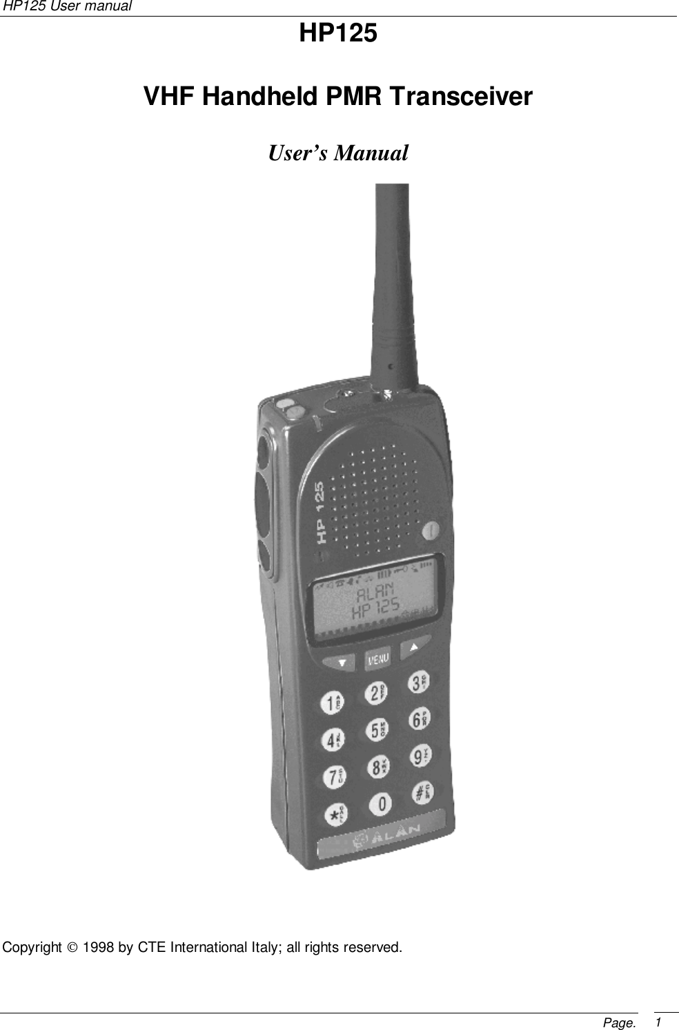
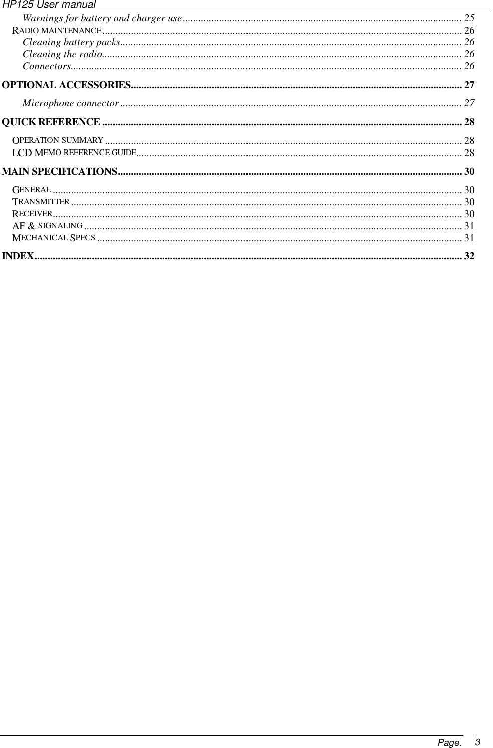
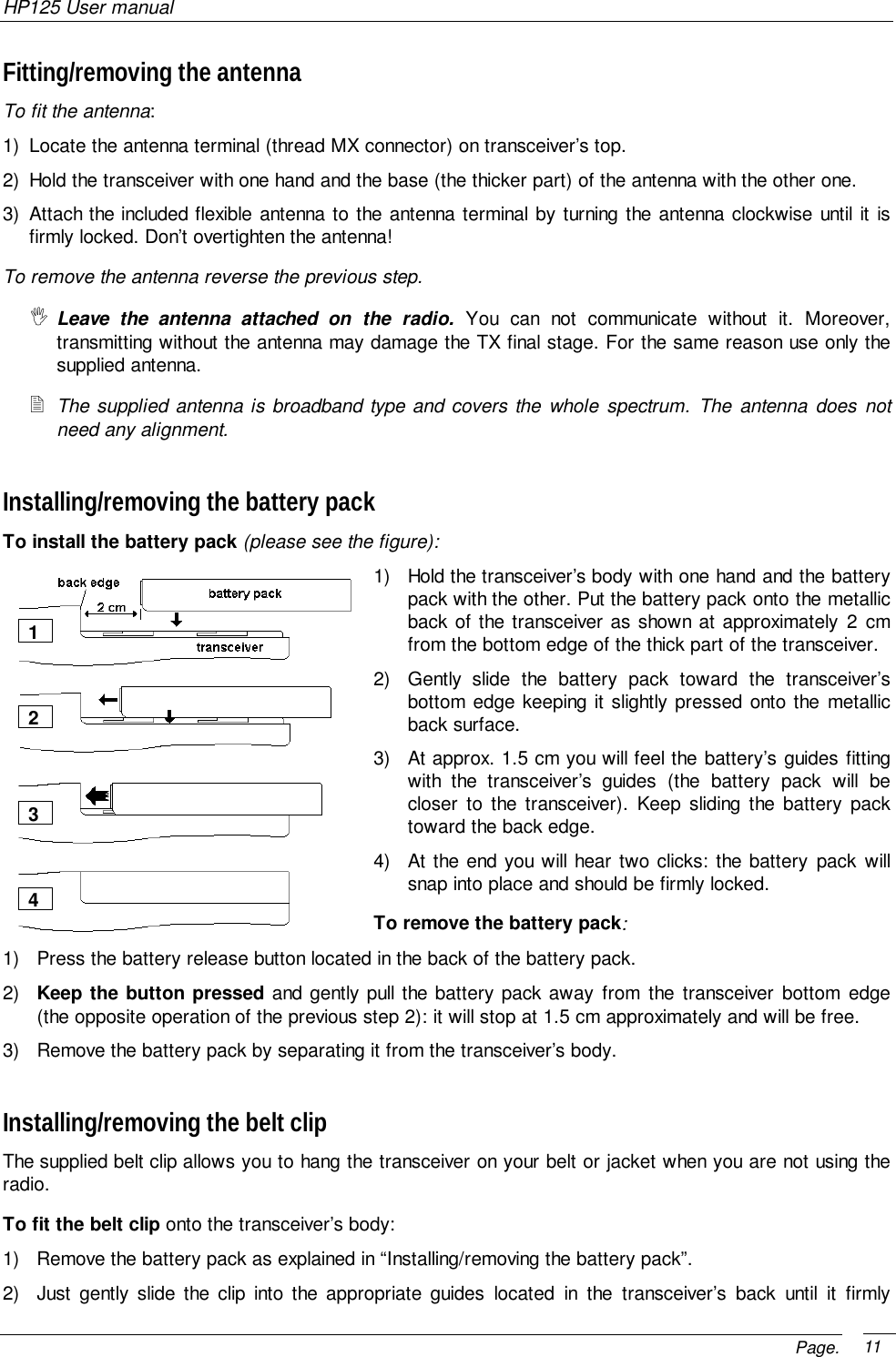
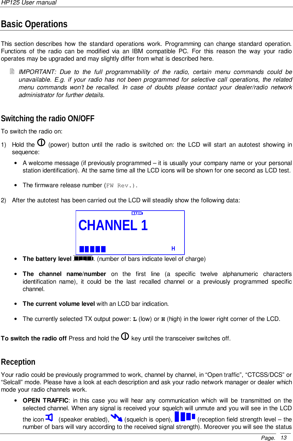
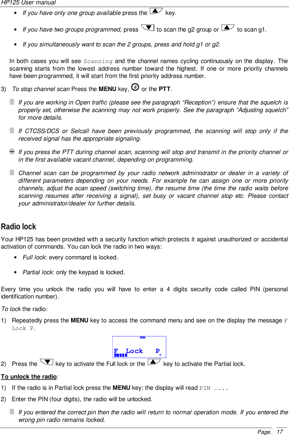
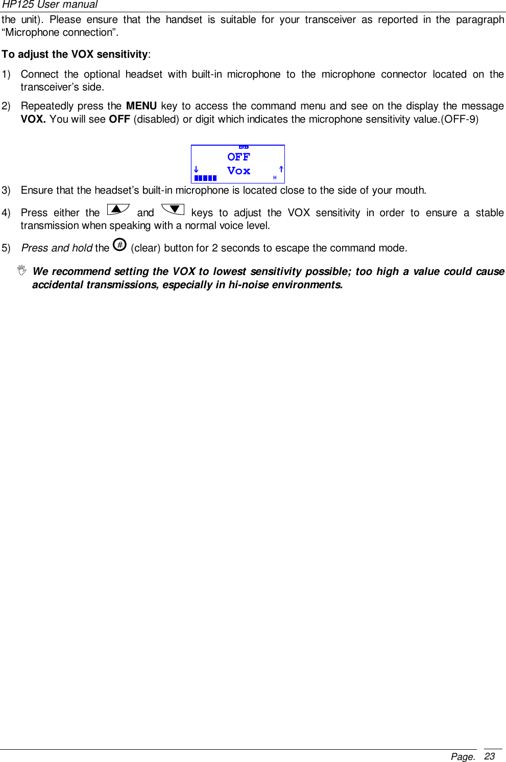
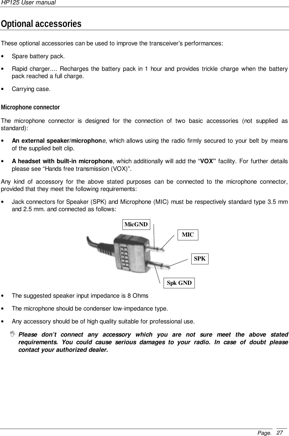
![HP125 User manualPage. 771389101112146Part Names and their functionsPlease have a look to the following parts description in order to familiarize with the transceiver’s main partsand controls. Numbers in brackets refer to the illustration.Top[1] Antenna connector. Fit the antenna to this connector(MX thread type).[2] Programming connector (under the protection cap - forauthorized dealers/service facilities only). Allows toprogram the radio (channels data) via a suitableprogrammer. It must be protected with the suppliedrubber cap when not in use[3] Status LED. Glows in different colors to show the current radio’s status.[4] Monitor button. Enables the speaker for monitoring of the tuned channel.[5] Emergency button. Sends an emergency selective call. (if enabled)Front[6] Speaker. The reception sound is emitted by the builtin speaker located at this point.[7] Power button. Press this key to turn thetransceiver on and off.[8] LCD display. Shows the radio’s parameters (channelnumber etc.). Icon and symbols are further explainedin the text “Display”. Whenever any key is pressed thedisplay is automatically backlit for a few seconds.[9] UP and Down buttons. For scrollingforward and backward through function list and forchanging channels, volume and function values.[10] Keypad. For entering digits of selective call (ifenabled) and letters for the related operations (e.g.SDM messages or Address Book). Whenever any keyis pressed the display is automatically backlit for a fewseconds.[11] Clear button. If pressed for two seconds incommand mode, radio reverts back to standby mode.In Selcall mode, deletes incorrectly entered digits (ifSelcall is enabled).[12] Call button. To send a valid call when usingselective call features. (Selcall - if enabled)[13] MENU button. Allows accessing the main menu.[14] Microphone. The microphone located in this placedetects your voice.1453 2](https://usermanual.wiki/Midland-Radio/ALHP425.Users-Manual/User-Guide-136291-Page-7.png)
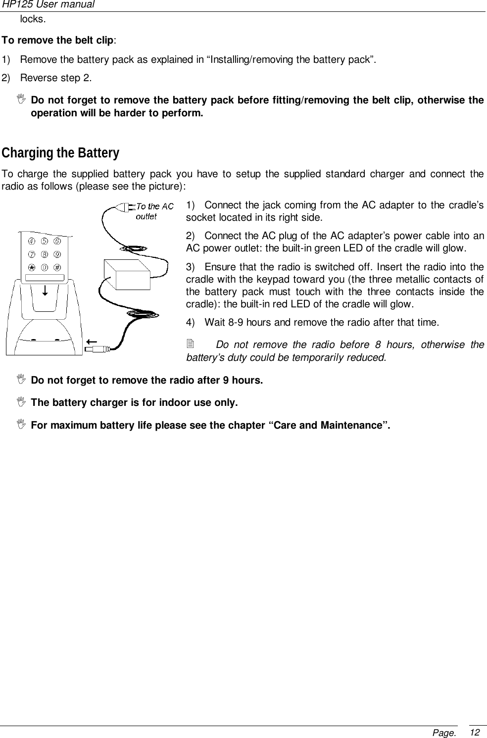
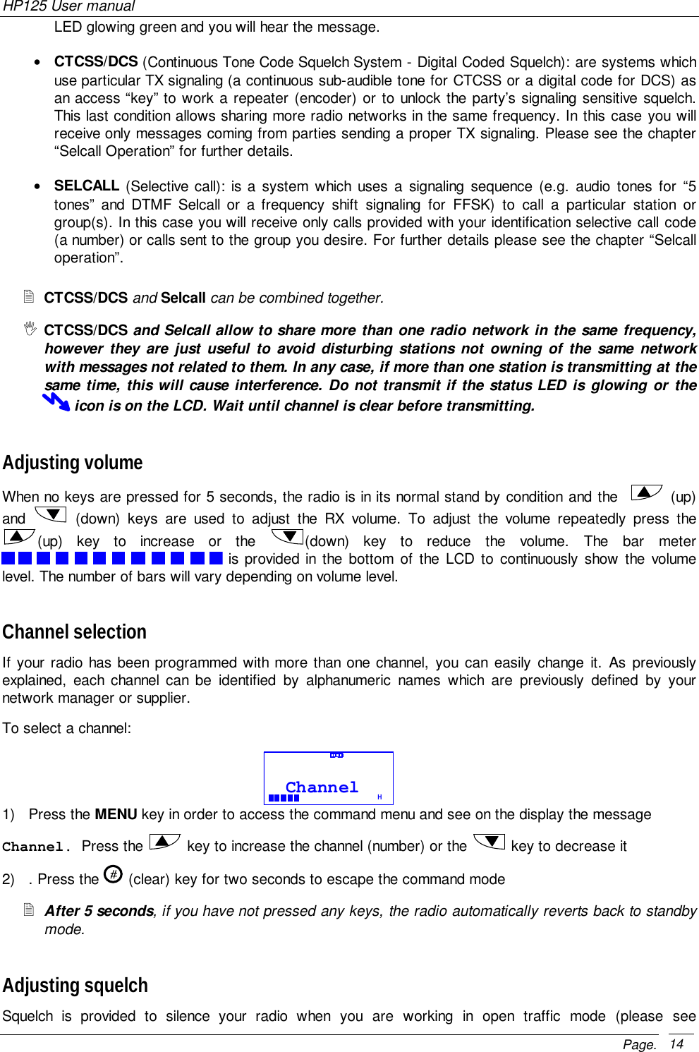
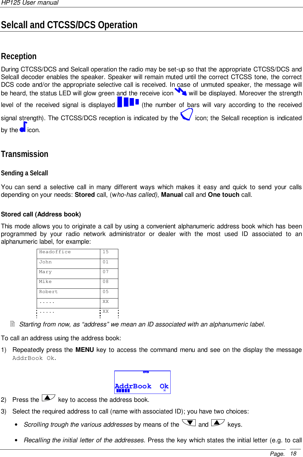
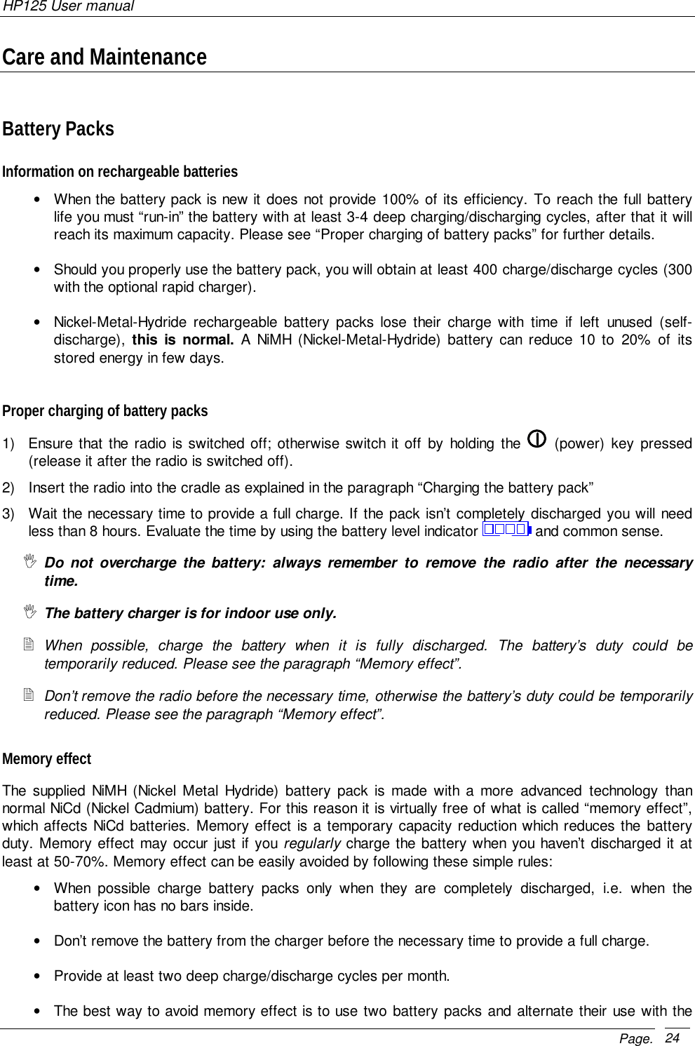
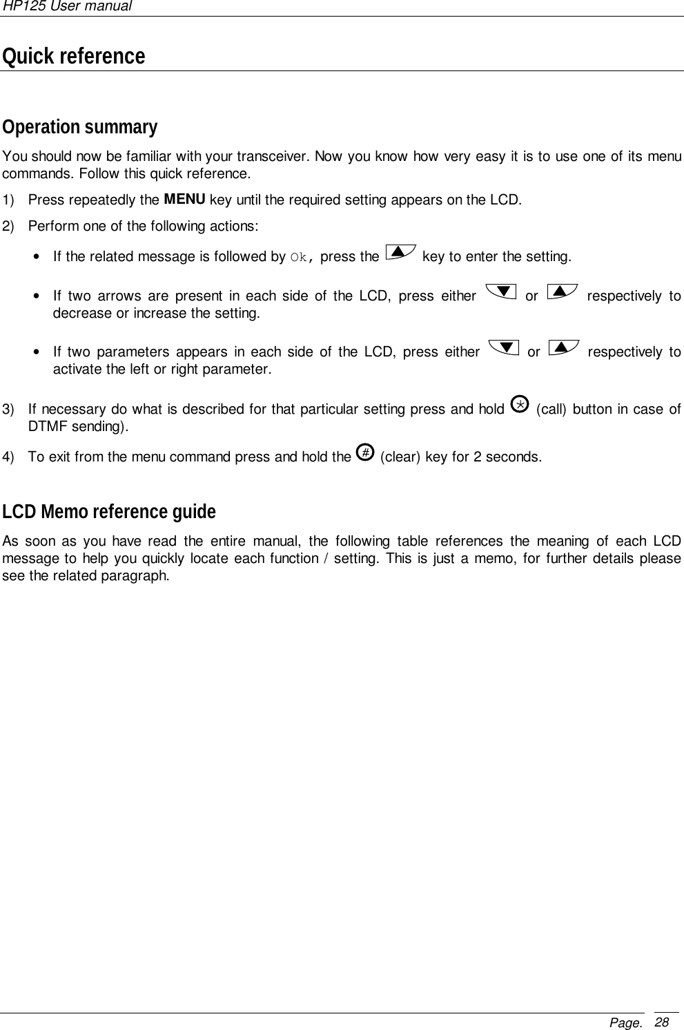
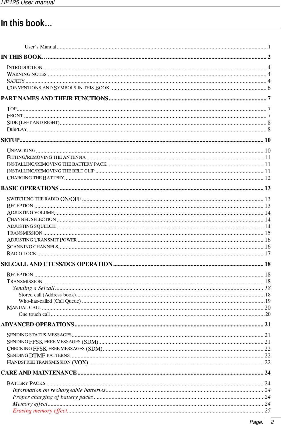
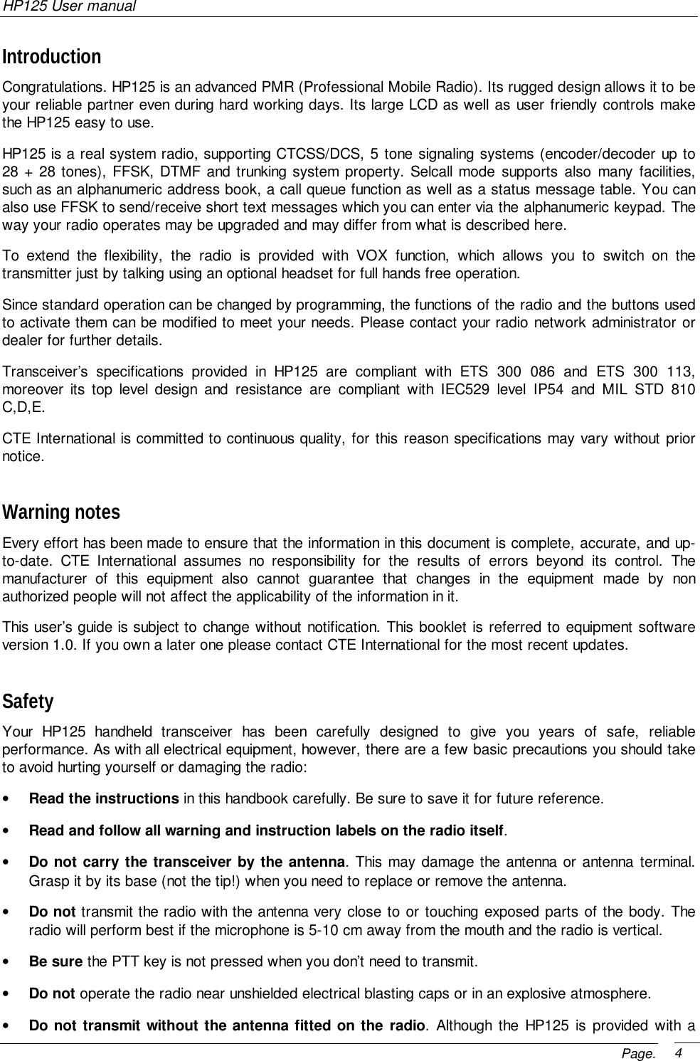
![HP125 User manualPage. 8Side (left and right)[15] Microphone connector. For remotespeaker/microphone, headsets for VOX use andother accessories. It must be protected with thesupplied rubber cap when not in use. For therelated pin connections please see to“Microphone connection”.[16] Battery pack. This NiMH battery pack suppliesenergy to your radio.[17] Release button (located on the battery’s body).Allows for removal of the battery pack.[18] CALL 1 button. Sends the selective call NO.1.(if enabled)[19] PTT (Push To Talk) button. Switches thetransceiver from receive to transmit whenpressed.[20] CALL 2 button. Sends the selective call NO. 2.(if enabled)DisplayThis section explains the meaning of the various indicators which may appear on the LCD of your HP125handheld transceiver:Radio is transmitting (status LED will glow red at the same time)Speaker is enabled (you will hear audio communications and/or noise) DTMF is enabledCTCSS/DCS tone detected Selective call detected Scrambler enabled Battery Level indicator (the number of bars will vary with level of charge) Keypad lock enabled Receive mode (squelch is open) Reception field strength level (the number of bars will vary with receive strength) Transmit output power currently selected, respectively high (H) or Low (L)151718162019](https://usermanual.wiki/Midland-Radio/ALHP425.Users-Manual/User-Guide-136291-Page-8.png)