Midland Radio GXT400 FRS/GMRS COMBINATION User Manual GXT400 Owner s Manual 2
Midland Radio Corporation FRS/GMRS COMBINATION GXT400 Owner s Manual 2
UserManual.wiki
>
Midland Radio
>
GXT400 User Manual
USERS MANUAL
Navigation menu
Upload a User Manual
Namespaces
Wiki Guide
HTML
PDF
Info
Views
User Manual
Discussion / Help
Navigation
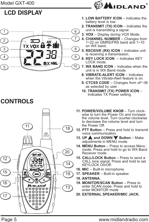
![®Model GXT-400Page 7 www.midlandradio.comCHARGING THE BATTERIESYour GXT-400 is equipped to allow using a rechargeable NiMH batterypack (not included) which can be recharged by an A/CCharger/Adaptor (not included) through the MIC [20] Jack of theradio, or using a Desktop Charger (not included). Batteries must becharged when the low battery icon flashes on the display.Initial charge time is 24 hours with a charge time of 8-12 hoursthereafter. For maximum battery life, we recommend charging thebatteries when the low battery indicator comes on.Remove the radios from the charger when the charge time expires.Accessories : XX-XXXXX - Wall adapter for charging through the MIC[20] Jack.18CVP3 - Desktop Charger with 2 Rechageable Battery PacksTo charge through the MIC Jack :- Connect the AC Adaptor/Charger into an A/C Wall Outlet- Insert the Adaptor/Charger jack into the MIC [20] Jack of the radio found at the side of the unit.To charge through a Desktop Charger:- Connect the AC Adaptor into an A/C Wall outlet- Insert the Adaptor Jack into the Desktop charger jack- Place the units into the Desktop Charger slot and note that the LEDindicator of the Desktop Charger will light up to indicate charging function.Note :1. Only use batteries indicated in the manual, or our NiMH battery pack.2. Do not attempt to charge Alkaline batteries or any batteries or battery packs other than the one indicated in the manual. This may cause leakage and damage the unit.3. For long term storage of the radio, turn the unit OFF and remove the batteries from the radio.](https://usermanual.wiki/Midland-Radio/GXT400/User-Guide-395663-Page-7.png)
![®Model GXT-400Page 8 www.midlandradio.comOPERATIONSPOWER ON/OFF AND VOLUME :Rotate the POWER/VOLUME [11] knob clockwise to turn the radio onand increase the volume level. Rotate it counter-clockwise to reducethe volume level and turn the radio off (after you hear the click sound).During Power On, the radio will beep 3 times with different tones, theLCD will display a “self-test” message for 1 second, the LCD Displaywill indicate the last channel selected.TRANSMISSION AND RECEPTION :To communicate, all radios in your group must be set to the samechannel and CTCSS Code.· For maximum clarity, hold the radio 2 to 3 inches from your mouth.· Press and hold the PTT [12] button and speak in a normal voice into the microphone. The TX [2] icon will appear continuously on the LCD Display when transmitting.· To receive a signal, release the PTT [12] button. The RX [5] icon will appear on the display when your radio is receiving a transmission.Note : The maximum communication range will vary dependingon the terrain and environment.MONITOR FUNCTION :Pressing and holding the MONITOR [19] button for 1 second will letyou hear noise so you can adjust the volume level of the radio whennot receiving a signal. This should be used to check activity on currentchannel before transmitting. Repeat the same procedure to exit.SCAN FUNCTION :Your GXT-400 can scan all of the 22 channel to observe for anyactivity. To enter, quickly press the SCAN [19] button. Repeat thesame procedure to exit.Your radio will rapidly scan each of the 22 channels and stop on anyactive channel for 5 seconds before resuming scan.When you press the PTT [12] button to transmit on an active channel,the scanning function will stop and remain on the active channel. Toresume scanning, quickly press the SCAN button [19].](https://usermanual.wiki/Midland-Radio/GXT400/User-Guide-395663-Page-8.png)
![®Model GXT-400Page 9 www.midlandradio.comCALL TONE FUNCTION :Your GXT-400 can transmit a call tone for a fixed length of time. Tosend a call tone, press the CALL [15] button. The TX [2] icon willappear during transmitting a call tone and a tone can be heard on thespeaker for confirmation. KEYPAD LOCK :To avoid accidentally changing the radio operation, press the LOCK[15] button for 4 seconds . The KEY LOCK [6] icon will appear on thedisplay. PTT [12] and CALL [15] will still be active. Repeat the sameprocedure to unlock the keypad. DISPLAY ILLUMINATION :During Power on, the display illumination will activate for approx. 7seconds. The display illumination can also be activated when theMENU [14] button is pressed.USER INTERFACECHANNEL SELECTION (GMRS/FRS BAND):Press the MENU [14] button once, and then the [13] buttons toselect one of the 22 GMRS/FRS channels. To confirm the selection,press the PTT [12] button or wait for 5 seconds roughly.MENU Channel VOX1~22 oF/Hi/LoCTCSSoF~38Roger BeepOn/OffPowerH/M/LCall Tone1~5VibrateOn/OffWX Channel1~10Press &hold Menubutton/](https://usermanual.wiki/Midland-Radio/GXT400/User-Guide-395663-Page-9.png)
![®Model GXT-400Page 10 www.midlandradio.comCTCSS SUB-TONE SETTING :Your GXT-400 has 38 CTCSS codes available. The selected CTCSScode may be different for each channel. To select a CTCSS code forthe current channel press the MENU [14] button twice, and then the[13] buttons to select one of the 22 channels. To confirm theselection, press the PTT [12] button or wait for 5 seconds roughlyNote : Selecting a CTCSS code of "oF" will disable the the CTCSSfeature. To communicate between two GXT-400 radios , both thechannel and CTCSS code selections must be the same.TRANSMIT (TX) POWER SELECTION :Your GXT-400 has 3 transmit power levels. To select the power levelon channels 1~7 and 15~22, press the MENU [14] button thee times,a “Pr” icon will appear on the display. Then press the [13] buttonsto select among the 3 TRANSMIT POWER [10] icon (H/M/L). To con-firm, press the PTT [12] button or wait for 5 seconds roughly.Note : There is no transmit power selection on Channel 8~14.VOX (Hands-free Transmission) FUNCTION:Your GXT-400 has 3 VOX level selection (oF/Lo/Hi).To activate the VOX function, press the MENU [14] button four times.The display shows “VOX” blinking while on the right of the CHAN-NEL NUMBER [4] display, an “oF” icon appears. Select “Lo” or “Hi” bypressing the [13] buttons and push the PTT[12] key, or wait for 5seconds for confirmation. The VOX functionwill be more sensitive onthe “Hi”setting than in the “Lo”setting.To deactivate the VOX function, press the MENU [14] button fourtimes. The display shows “VOX” blinking while on the right of theCHANNEL NUMBER [4] display, an “on” icon appears. Select “oF” bypressing the [13] buttons and push the PTT[12] key, or wait for 5seconds for confirmation.////](https://usermanual.wiki/Midland-Radio/GXT400/User-Guide-395663-Page-10.png)
![®Model GXT-400Page 11 www.midlandradio.comVIBRATE-ALERT FUNCTION :Your GXT-400 is equipped with a VIBRATE-ALERT function for silentoperation of the radio. The radio will vibrate when receiving a call tonetransmission instead of emitting a call tone sound. To activate the VIBRATE-ALERT mode, press the MENU [14] buttonfive times, the display will show the VIBRATE-ALERT [8] icon blinkingwhile on the right of the CHANNEL NUMBER [4] display, an “oF” iconappears. Select “on” by pressing the [13] buttons and push thePTT[12] key, or wait for 5 seconds for confirmation. The VIBRATE-ALERT [8] icon will remain on the display.To de-activate the VIBRATE-ALERT mode, press the MENU [14]button five times, the display will show the VIBRATE-ALERT [8] iconblinking while on the right of the CHANNEL NUMBER [4] display, an“on” icon appears. Select “oF” by pressing the [13] buttons andpush the PTT[12] key, or wait for 5 seconds for confirmation. TheVIBRATE-ALERT [8] icon will disappear on the display.ROGER BEEP (end of transmission) TONE :When the PTT [12] button is released, the radio will beep to confirm toother users that your transmission has finished. To activate the ROGER BEEP tone , press the MENU [14] button sixtimes, the display will show an “rb” icon while on the right of the “rb”[4] display, an “oF” icon appears. Select “on” by pressing the[13] buttons and push the PTT[12] key, or wait for 5 seconds forconfirmation. To de-activate the ROGER BEEP tone , press the MENU [14] buttonsix times, the display will show an “rb” icon while on the right of the“rb” [4] display, an “on” icon appears. Select “oF” by pressing the[13] buttons and push the PTT[12] key, or wait for 5 seconds forconfirmation.////](https://usermanual.wiki/Midland-Radio/GXT400/User-Guide-395663-Page-11.png)
![®Model GXT-400Page 12 www.midlandradio.comCALL TONE SELECTION :Your GXT-400 has 5 user-selectable CALL TONE. To select, press theMENU [14] button seven times, a “CA” icon will appear on the displaywhile on the right of the “CA” icon the current CALL TONE setting isdisplayed. Then press the [13] buttons to select among the 5CALL TONE selections, the radio will emit the corresponding tone foreach selection. To confirm, press the PTT [12] button or wait for 5 sec-onds roughly.WEATHER (WX) BAND RECEIVER FUNCTION :Your GXT-400 has a WEATHER (WX) BAND RECEIVER function, toenable user to receive Weather alert/report from designated NOAAstations.To activate the WEATHER (WX) RECEIVER function, press and holdthe MENU [14] button around 3 seconds. The current WX CHANNEL[4] and the WX BAND [7] icon will appear on the display.Then press the [13] buttons to select one of the ten WX BANDchannel. To confirm, press the PTT [12] button or wait for 5 secondsroughly.To de-activate the WEATHER (WX) RECEIVER function, press andhold the MENU [14] button around 3 seconds. The currentGMRS/FRS radio setting will be displayed and the WX BAND icon willdisappear.//](https://usermanual.wiki/Midland-Radio/GXT400/User-Guide-395663-Page-12.png)
![®Model GXT-400Page 13 www.midlandradio.comEXTERNAL SPEAKER/MICROPHONE JACK :Your GXT-400 can be used with an optional external speaker/micro-phone or headset, freeing your hands for other tasks. To use anoptional / speaker / microphone or headset:· Insert the plug(s) into the SPK/MIC [20] jacks· Place the earbud into your ear, and adjust themic into your desired position.INSTALLING THE BELT CLIP :To install the BELT CLIP, slide the clipdown into the slot on the back of theradio until the BELT CLIP LATCH clicks.To remove the BELT CLIP, press theLOCK TAB down , then gently pull thebelt clip up toward the top of the radio.BELT CLIPLOCK TABBELT CLIP LATCH](https://usermanual.wiki/Midland-Radio/GXT400/User-Guide-395663-Page-13.png)