Midland Radio GXT400 FRS/GMRS COMBINATION User Manual GXT400 Owner s Manual 2
Midland Radio Corporation FRS/GMRS COMBINATION GXT400 Owner s Manual 2
USERS MANUAL
GXT-400 GMRS/FRS Radio
with Weather Band Receive
r
X-TRA TALK
®
OWNER'S MANUAL
www.midlandradio.com
TM

®
Model GXT-400
Page 2 www.midlandradio.com
TABLE OF CONTENTS
Introduction 3
Important Notice, FCC Licensing 4
LCD Display 5
Controls 5
Battery Installation 6
Charging the Batteries 7
Operations 8 - 12
External Speaker/Microphone Jack 13
Installing the Belt Clip 13
Problems & Solutions 14
Use and Care 14
Specifications and Frequency Charts 15
Warranty Information 16
MIDLAND Family Products 17

®
Model GXT-400
Page 3 www.midlandradio.com
Welcome to the world of Midland electronics
Congratulation on your purchase of a quality MIDLAND product. Your
GXT-400 represents the state-of-the-art in high-tech engineering.
Designed for General Mobile Radio Service operation, this compact
package is big in performance. It is a quality piece of electronic
equipment, skillfully constructed with the finest components. The
circuitry is all solid-state and mounted on a rugged printed circuit
board. Your GXT-400 is designed for reliable and trouble-free
performance.
Features
- 22 GMRS/FRS Channel with 38 CTCSS Code
- VOX
- 3-selectable CALL Tone
- Weather (WX) Band Receiver
- Vibrate-Alert
- SCAN function
- MONITOR function
- Roger Beep Tone
This device complies with Part 15 of the FCC Rules. Operation is subject to
the following two conditions : (1) this device does not cause harmful
interference, and (2) this radio must accept any interference that may cause
undesired operation.
To maintain compliance with FCC’s RF exposure suidelines, for body-worn
operation, this radio has been tested and meets the FCC RF exposure
guidelines when used with Midland Radio Corp. accessories supplied or
designated for this product. Use of other accessories may not ensure
compliance with FCC RF exposure guidelines. (Tested with Headset Model:
AVP-1)

®
Model GXT-400
Page 4 www.midlandradio.com
IMPORTANT NOTICE, FCC LICENCE REQUIRED
The GXT-400 operate on GMRS (General Mobile Radio Service) frequencies
which require an FCC (Federal Communications Commission) license.
Information on how to apply for a license is included in the owner's manual. A
user must be licensed prior to operating on channels 1 - 7 or 15 - 22, which com-
prise the GMRS channels of the GXT-400. Serious penalties could result for unli-
censed use of GMRS channels, in violation of FCC rules, as stipulated in the
Communications Act's Sections 501 and 502 (amended).
Licensed users will be issued a call sign by the FCC which should be used for
station identification when operating the GXT-400. GMRS users should also
cooperate by engaging in permissible transmissions only, avoiding channel
interference with other GMRS users, and being prudent with the length of their
transmission time.
Questions regarding the license application should be directed to the FCC at 1-
886-CALL FCC. Additional information is available on the FCC's web-site at
www.fcc.gov/wtb/prs/genmbl.html
Exposure To Radio Frequency Energy
Your Midland radio is designed to comply with the following national and
international standards and guidelines regarding exposure of human being to
radio frequency electromagnetic energy:
- United States Federal Communications Commission, Code of Federal
Regulations: 47 CFR part 2 sub-part J
- American National Standards Institute (ANSI)/Institute of Electrical &
Electronic Engineers (IEEE) C95. 1-1992
- Institute of Electrical and Electronic Engineer (IEEE) C95. 1-1999 Edition
- National Council on Radiation Protection and Measurements (NCRP) of the
United States, Report 86, 1986
- International Commission on Non-lonizing Radiation Protection (ICNIRP)
1998
To control your exposure and ensure compliance with the general population
or uncontrolled environment exposure limits, transmit no more than 50% of the
time. The radio generates measurable RF energy exposure only when
transmitting.
®
Model GXT-400
Page 5 www.midlandradio.com
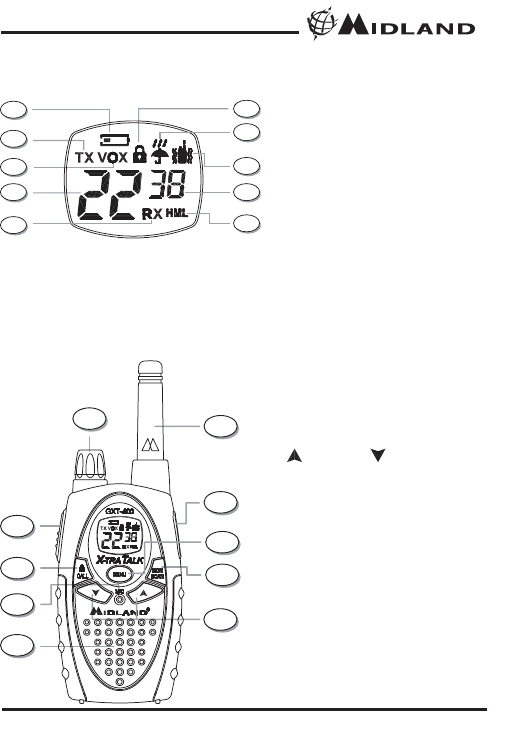
CONTROLS
LCD DISPLAY
1. LOW BATTERY ICON – Indicates the
battery level is low.
2. TRANSMIT (TX) ICON – Indicates the
unit is transmitting a signal.
3. VOX – Display during VOX Mode.
4. CHANNEL NUMBER – Changes from
1~22 on GMRS/FRS band and 1~10
on WX band.
5. RECEIVE (RX) ICON – Indicates unit
is receiving a transmission.
6. KEY LOCK ICON – Indicates KEY
LOCK mode.
7. WX BAND ICON – Indicates when the
unit is in WX Band mode.
8. VIBRATE-ALERT ICON – Indicates
when the Vibrate-Alert feature is on.
9. CTCSS CODE – Changes from oF~38
as selected by user .
10. TRANSMIT (TX) POWER ICON –
Indicates TX Power setting.
11. POWER/VOLUME KNOB – Turn clock-
wise to turn the Power On and increase
the volume level. Turn counter-clockwise
to decrease the volume level and turn
the Power Off.
12. PTT Button – Press and hold to transmit
voice communication.
13. UP and DOWN Button – Make
adjustments in MENU mode.
14. MENU Button – Press to access Menu
mode. Press and hold to go to WX Band
Receiver mode .
15. CALL/LOCK Button – Press to send a
CALL tone signal. Press and hold to set
KEYLOCK On/Off.
16. MIC – Built-in microphone.
17. SPEAKER – Built-in speaker.
18. ANTENNA.
19. MONITOR/SCAN Button – Press to
enter SCAN mode. Press and hold to
enter MONITOR mode
20. EXTERNAL SPEAKER/MIC JACK.
1
2
3
4
5
6
7
8
9
10
11
12
15
16
17
13
19
14
20
18
®
Model GXT-400
Page 6 www.midlandradio.com
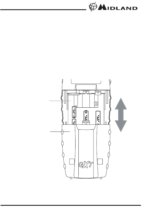
BATTERY INSTALLATION
Your GXT-400 radio operates with either 4 AA Alkaline Batteries or
optional NiMH Battery Pack. The belt clip should be removed (Page
13) to ease installation or removal. To install the batteries:
1. With the back of the radio facing you, remove the Battery Cover
by sliding it down from the unit.
2. Insert 4 AA batteries observing the polarity as shown. Installing
the batteries incorrectly will prevent the unit from operating or can
damage the unit.
3. Return the Battery Cover by sliding it up from the unit.
BATTERY
COMPARTMENT
BATTERY
COMPARTMENT
COVER

®
Model GXT-400
Page 7 www.midlandradio.com
CHARGING THE BATTERIES
Your GXT-400 is equipped to allow using a rechargeable NiMH battery
pack (not included) which can be recharged by an A/C
Charger/Adaptor (not included) through the MIC [20] Jack of the
radio, or using a Desktop Charger (not included). Batteries must be
charged when the low battery icon flashes on the display.
Initial charge time is 24 hours with a charge time of 8-12 hours
thereafter. For maximum battery life, we recommend charging the
batteries when the low battery indicator comes on.
Remove the radios from the charger when the charge time expires.
Accessories : XX-XXXXX - Wall adapter for charging through the
MIC[20] Jack.
18CVP3 - Desktop Charger with 2 Rechageable
Battery Packs
To charge through the MIC Jack :
- Connect the AC Adaptor/Charger into an A/C Wall Outlet
- Insert the Adaptor/Charger jack into the MIC [20] Jack of the radio
found at the side of the unit.
To charge through a Desktop Charger:
- Connect the AC Adaptor into an A/C Wall outlet
- Insert the Adaptor Jack into the Desktop charger jack
- Place the units into the Desktop Charger slot and note that the LED
indicator of the Desktop Charger will light up to indicate charging
function.
Note :
1. Only use batteries indicated in the manual, or our NiMH battery
pack.
2. Do not attempt to charge Alkaline batteries or any batteries or
battery packs other than the one indicated in the manual. This
may cause leakage and damage the unit.
3. For long term storage of the radio, turn the unit OFF and remove
the batteries from the radio.

®
Model GXT-400
Page 8 www.midlandradio.com
OPERATIONS
POWER ON/OFF AND VOLUME :
Rotate the POWER/VOLUME [11] knob clockwise to turn the radio on
and increase the volume level. Rotate it counter-clockwise to reduce
the volume level and turn the radio off (after you hear the click sound).
During Power On, the radio will beep 3 times with different tones, the
LCD will display a “self-test” message for 1 second, the LCD Display
will indicate the last channel selected.
TRANSMISSION AND RECEPTION :
To communicate, all radios in your group must be set to the same
channel and CTCSS Code.
· For maximum clarity, hold the radio 2 to 3 inches from your mouth.
· Press and hold the PTT [12] button and speak in a normal voice
into the microphone. The TX [2] icon will appear continuously on
the LCD Display when transmitting.
· To receive a signal, release the PTT [12] button. The RX [5] icon
will appear on the display when your radio is receiving a
transmission.
Note : The maximum communication range will vary depending
on the terrain and environment.
MONITOR FUNCTION :
Pressing and holding the MONITOR [19] button for 1 second will let
you hear noise so you can adjust the volume level of the radio when
not receiving a signal. This should be used to check activity on current
channel before transmitting. Repeat the same procedure to exit.
SCAN FUNCTION :
Your GXT-400 can scan all of the 22 channel to observe for any
activity. To enter, quickly press the SCAN [19] button. Repeat the
same procedure to exit.
Your radio will rapidly scan each of the 22 channels and stop on any
active channel for 5 seconds before resuming scan.
When you press the PTT [12] button to transmit on an active channel,
the scanning function will stop and remain on the active channel. To
resume scanning, quickly press the SCAN button [19].
®
Model GXT-400
Page 9 www.midlandradio.com
CALL TONE FUNCTION :
Your GXT-400 can transmit a call tone for a fixed length of time. To
send a call tone, press the CALL [15] button. The TX [2] icon will
appear during transmitting a call tone and a tone can be heard on the
speaker for confirmation.
KEYPAD LOCK :
To avoid accidentally changing the radio operation, press the LOCK
[15] button for 4 seconds . The KEY LOCK [6] icon will appear on the
display. PTT [12] and CALL [15] will still be active. Repeat the same
procedure to unlock the keypad.
DISPLAY ILLUMINATION :
During Power on, the display illumination will activate for approx. 7
seconds. The display illumination can also be activated when the
MENU [14] button is pressed.
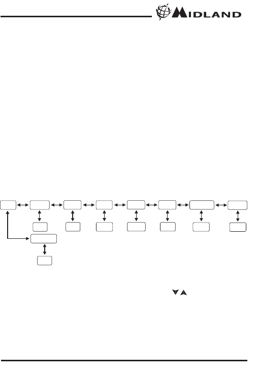
USER INTERFACE
CHANNEL SELECTION (GMRS/FRS BAND):
Press the MENU [14] button once, and then the [13] buttons to
select one of the 22 GMRS/FRS channels. To confirm the selection,
press the PTT [12] button or wait for 5 seconds roughly.
MENU Channel VOX
1~22 oF/Hi/Lo
CTCSS
oF~38
Roger Beep
On/Off
Power
H/M/L
Call Tone
1~5
Vibrate
On/Off
WX Channel
1~10
Press &
hold Menu
button
/

®
Model GXT-400
Page 10 www.midlandradio.com
CTCSS SUB-TONE SETTING :
Your GXT-400 has 38 CTCSS codes available. The selected CTCSS
code may be different for each channel. To select a CTCSS code for
the current channel press the MENU [14] button twice, and then the
[13] buttons to select one of the 22 channels. To confirm the
selection, press the PTT [12] button or wait for 5 seconds roughly
Note : Selecting a CTCSS code of "oF" will disable the the CTCSS
feature. To communicate between two GXT-400 radios , both the
channel and CTCSS code selections must be the same.
TRANSMIT (TX) POWER SELECTION :
Your GXT-400 has 3 transmit power levels. To select the power level
on channels 1~7 and 15~22, press the MENU [14] button thee times,
a “Pr” icon will appear on the display. Then press the [13] buttons
to select among the 3 TRANSMIT POWER [10] icon (H/M/L). To con-
firm, press the PTT [12] button or wait for 5 seconds roughly.
Note : There is no transmit power selection on Channel 8~14.
VOX (Hands-free Transmission) FUNCTION:
Your GXT-400 has 3 VOX level selection (oF/Lo/Hi).
To activate the VOX function, press the MENU [14] button four times.
The display shows “VOX” blinking while on the right of the CHAN-
NEL NUMBER [4] display, an “oF” icon appears. Select “Lo” or “Hi” by
pressing the [13] buttons and push the PTT[12] key, or wait for 5
seconds for confirmation. The VOX functionwill be more sensitive on
the “Hi”setting than in the “Lo”setting.
To deactivate the VOX function, press the MENU [14] button four
times. The display shows “VOX” blinking while on the right of the
CHANNEL NUMBER [4] display, an “on” icon appears. Select “oF” by
pressing the [13] buttons and push the PTT[12] key, or wait for 5
seconds for confirmation.
/
/
/
/

®
Model GXT-400
Page 11 www.midlandradio.com
VIBRATE-ALERT FUNCTION :
Your GXT-400 is equipped with a VIBRATE-ALERT function for silent
operation of the radio. The radio will vibrate when receiving a call tone
transmission instead of emitting a call tone sound.
To activate the VIBRATE-ALERT mode, press the MENU [14] button
five times, the display will show the VIBRATE-ALERT [8] icon blinking
while on the right of the CHANNEL NUMBER [4] display, an “oF” icon
appears. Select “on” by pressing the [13] buttons and push the
PTT[12] key, or wait for 5 seconds for confirmation. The VIBRATE-
ALERT [8] icon will remain on the display.
To de-activate the VIBRATE-ALERT mode, press the MENU [14]
button five times, the display will show the VIBRATE-ALERT [8] icon
blinking while on the right of the CHANNEL NUMBER [4] display, an
“on” icon appears. Select “oF” by pressing the [13] buttons and
push the PTT[12] key, or wait for 5 seconds for confirmation. The
VIBRATE-ALERT [8] icon will disappear on the display.
ROGER BEEP (end of transmission) TONE :
When the PTT [12] button is released, the radio will beep to confirm to
other users that your transmission has finished.
To activate the ROGER BEEP tone , press the MENU [14] button six
times, the display will show an “rb” icon while on the right of the “rb”
[4] display, an “oF” icon appears. Select “on” by pressing the
[13] buttons and push the PTT[12] key, or wait for 5 seconds for
confirmation.
To de-activate the ROGER BEEP tone , press the MENU [14] button
six times, the display will show an “rb” icon while on the right of the
“rb” [4] display, an “on” icon appears. Select “oF” by pressing the
[13] buttons and push the PTT[12] key, or wait for 5 seconds for
confirmation.
/
/
/
/

®
Model GXT-400
Page 12 www.midlandradio.com
CALL TONE SELECTION :
Your GXT-400 has 5 user-selectable CALL TONE. To select, press the
MENU [14] button seven times, a “CA” icon will appear on the display
while on the right of the “CA” icon the current CALL TONE setting is
displayed. Then press the [13] buttons to select among the 5
CALL TONE selections, the radio will emit the corresponding tone for
each selection. To confirm, press the PTT [12] button or wait for 5 sec-
onds roughly.
WEATHER (WX) BAND RECEIVER FUNCTION :
Your GXT-400 has a WEATHER (WX) BAND RECEIVER function, to
enable user to receive Weather alert/report from designated NOAA
stations.
To activate the WEATHER (WX) RECEIVER function, press and hold
the MENU [14] button around 3 seconds. The current WX CHANNEL
[4] and the WX BAND [7] icon will appear on the display.
Then press the [13] buttons to select one of the ten WX BAND
channel. To confirm, press the PTT [12] button or wait for 5 seconds
roughly.
To de-activate the WEATHER (WX) RECEIVER function, press and
hold the MENU [14] button around 3 seconds. The current
GMRS/FRS radio setting will be displayed and the WX BAND icon will
disappear.
/
/
®
Model GXT-400
Page 13 www.midlandradio.com
EXTERNAL SPEAKER/MICROPHONE JACK :
Your GXT-400 can be used with an optional external speaker/micro-
phone or headset, freeing your hands for other tasks. To use an
optional / speaker / microphone or headset:
· Insert the plug(s) into the SPK/MIC [20] jacks
· Place the earbud into your ear, and adjust the
mic into your desired position.
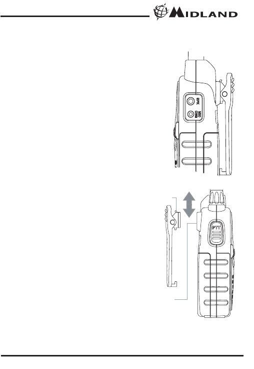
INSTALLING THE BELT CLIP :
To install the BELT CLIP, slide the clip
down into the slot on the back of the
radio until the BELT CLIP LATCH clicks.
To remove the BELT CLIP, press the
LOCK TAB down , then gently pull the
belt clip up toward the top of the radio.
BELT CLIP
LOCK TAB
BELT CLIP
LATCH

®
Model GXT-400
Page 14 www.midlandradio.com
PROBLEM SOLUTION
No Power - Check battery installation and/or replace batteries
Cannot Receive
Messages
- Confirm the radios have the same channel
settings.
- Make sure the you are with in range of the other
transceivers.
- Buildings and other may interfere with your
communication.
Radio is not responding
to button presses
- Make sure key lock is not on. See "Keypad Lock"
(Page 9).
- Radio might need to be reset. Turn radio off then
on.
- Ensure accessory microphone is set properly
Display is dim - Recharge or replace batteries.
Charger not functioning - Contacts on the bottom of the radio may require
cleaning.
- Ensure the outlet the charger is plugged into is
functioning properly.
- Check that the batteries are installed in the radio
properly.
USE AND CARE :
1. Do not use alcohol or cleaning solutions to clean the radio.
2. Do not immerse the radio in water.
3. Use a soft damp cloth to clean the radio
4. Dry the radio with dry lint-free cloth should it get wet.
5. Turn off the radio and remove the batteries during long-term
storage.
If you have a problem which you believe requires service, please
call first and speak with a service technician. Many problems can
be remedied over the phone without returning the unit for
service.
®
Model GXT-400
Page 15 www.midlandradio.com
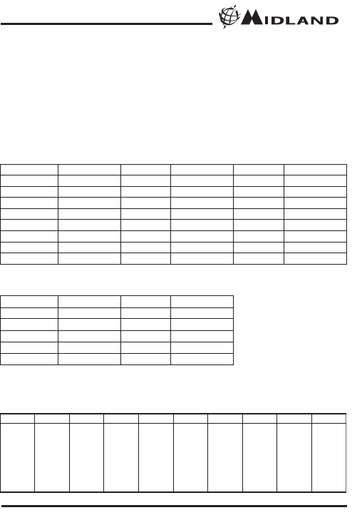
SPECIFICATIONS
Channels 22 GMRS/FRS Channels +38 CTCSS Codes
10 Weather (WX) Band Channels
Operating Frequency UHF 462.5500 ~ 467.7125 MHz
Power Source 4 AA Alkaline or Rechargeable Ni-MH Batteries
Output Power 2W ERP Max.
Range About 7 Miles
Battery Life Varies per user
GMRS/FRS FREQUENCY CHART (MHz)
CH. No CH. Freq. CH. No CH. Freq. CH. No CH. Freq.
1 462.5625 9 467.5875 17 462.6000
2 462.5875 10 467.6125 18 462.6250
3 462.6125 11 467.6375 19 462.6500
4 462.6375 12 467.6625 20 462.6750
5 462.6625 13 467.6875 21 462.7000
6 462.6875 14 467.7125 22 462.7250
7 462.7125 15 462.5500
8 467.5625 16 462.5750
WEATHER (WX) RECEIVER FREQUENCY CHART (MHz)
CH. No CH. Freq. CH. No CH. Freq.
1 162.550 6 162.500
2 162.400 7 162.525
3 162.475 8 161.650
4 162.425 9 161.775
5 162.450 10 163.275
CTCSS CODES FREQUENCY CHART (Hz)
Code Freq. Code Freq. Code Freq. Code Freq. Code Freq.
1 67.0 9 91.5 17 118.8 25 156.7 33 210.7
2 71.9 10 94.8 18 123.0 26 162.2 34 218.1
3 74.4 11 97.4 19 127.3 27 167.9 35 225.7
4 77.0 12 100.0 20 131.8 28 173.8 36 233.6
5 79.7 13 103.5 21 136.5 29 179.9 37 241.8
6 82.5 14 107.2 22 141.3 30 186.2 38 250.3
7 85.4 15 110.9 23 146.2 31 192.8
8 88.5 16 114.8 24 151.4 32 203.5
*** Channel 8,9 and 10 is for Canadian Marine Frequency

®
Model GXT-400
Page 16 www.midlandradio.com
LIMITED WARRANTY
Midland Radio Corporation will repair or replace, at its option without
charge, any Midland FRS/GMRS transceiver which fails due to a
defect in material or workmanship within Three Years following the
initial consumer purchase. This warranty does not apply to water
damage, battery leak or abuse.
This warranty does not include any carrying cases, earphones, or
antennas, which may be a part of or included with the warranted
product, or the cost of labor for removal or re-installation of the
product in a vehicle or other mounting.
Performance of any obligation under this warranty may be obtained by
returning the warranted product, freight prepaid, along with proof of
purchase to:
Midland Radio Corporation
Warranty Service Department
1120 Clay Street
North Kansas City, Missouri 64116
This warranty gives you specific legal rights, and you may also have
other rights, which vary from state to state.
Note : The above warranty applies only to merchandise purchased in
the United States of America or any of the territories or possessions
thereof, or from a U.S. Military exchange.
Midland Radio Corporation
1120 Clay Street
North Kansas City, MO 64116
Tel: (816) 241-8500
E-mail: mail@midlandradio.com
URL: www.midlandradio.com

®
Model GXT-400
Page 17 www.midlandradio.com

®
Model GXT-400
Page 18 www.midlandradio.com
MIDLAND RADIO CORPORATION
1120 Clay St.
N. Kansas City MO 64116
Call 816.241.8500
visit us at http://www.midlandradio.com
Note: Features & Specifications are subject to Change without notice.
MIDLAND is not responsible for unintentional errors or omissions on its
packaging.