Midland Radio PL150 PL2415/PL2215 Mobile radio User Manual ACC 905
Midland Radio Corporation PL2415/PL2215 Mobile radio ACC 905
UserManual.wiki
>
Midland Radio
>
PL150 User Manual
>
Programming manual
Contents
1.
Manual
2.
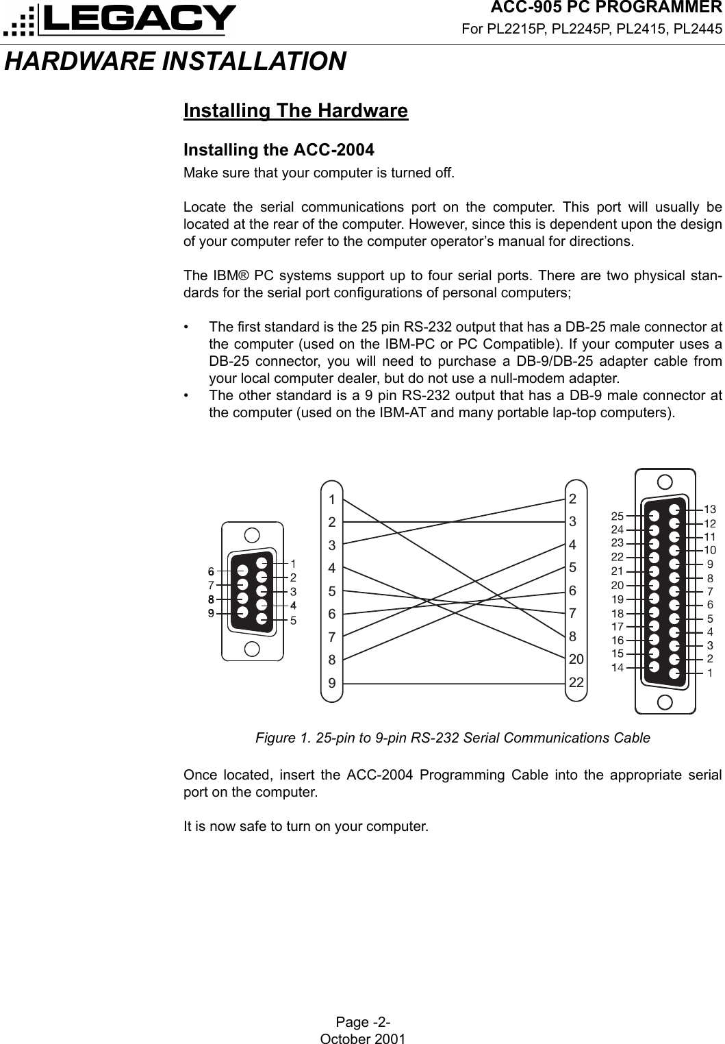
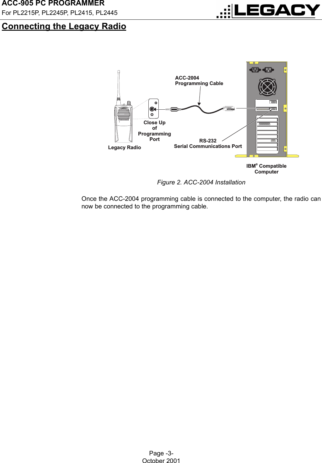
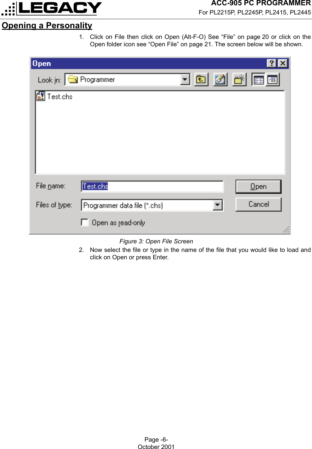
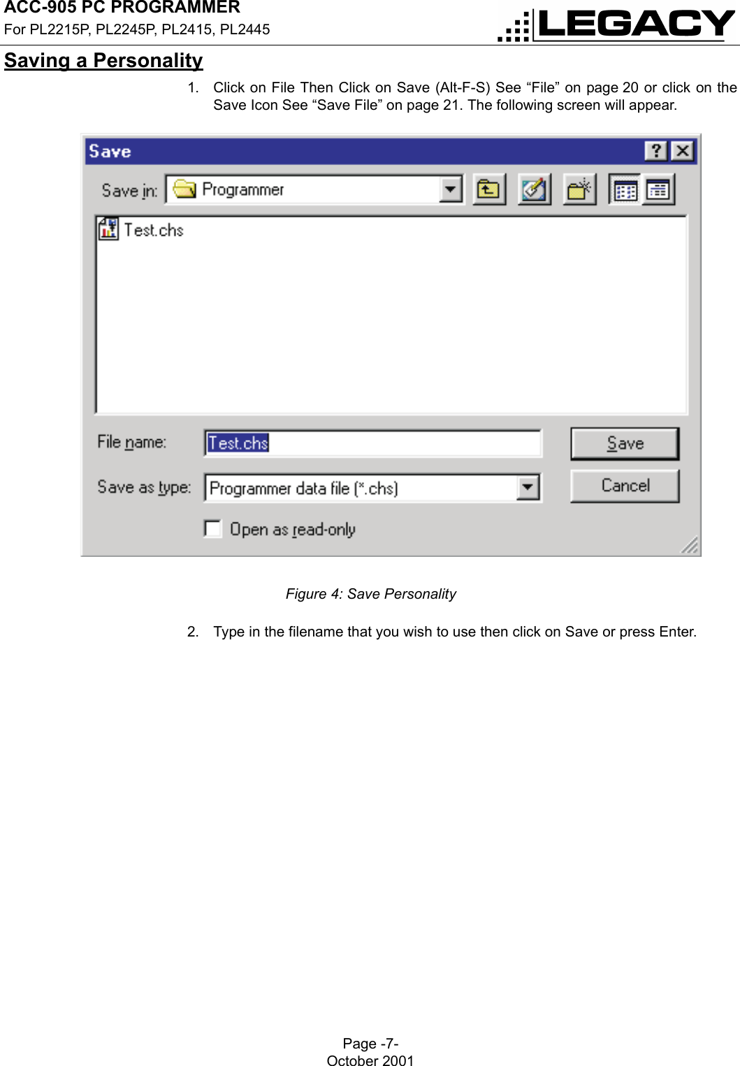
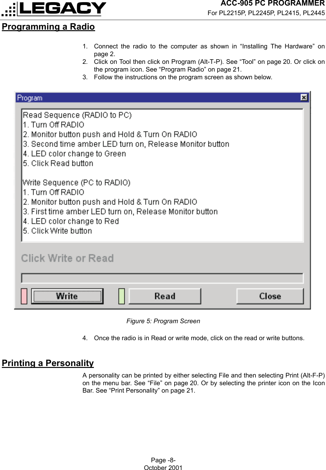
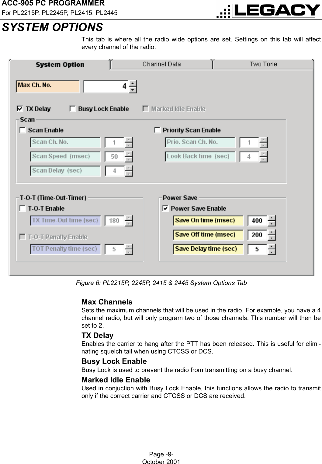
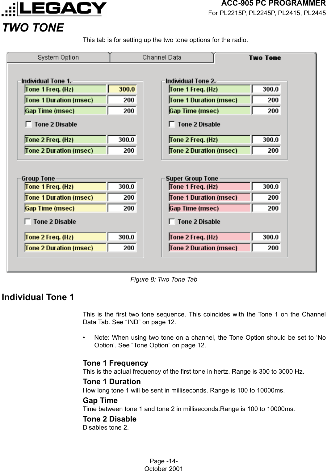
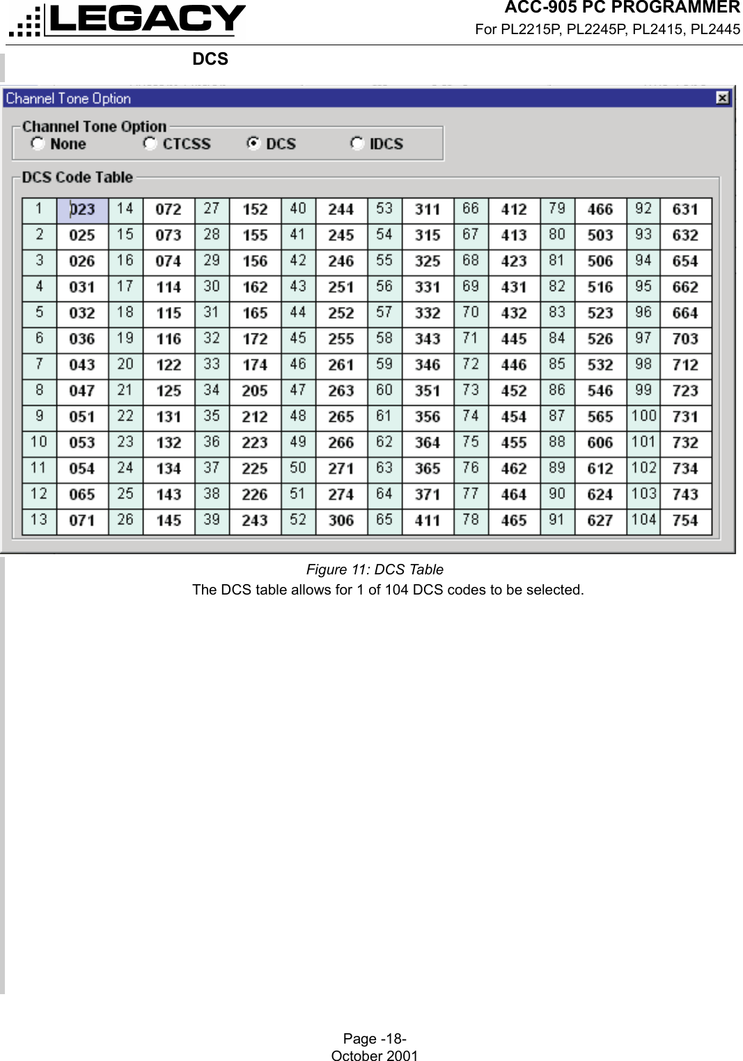
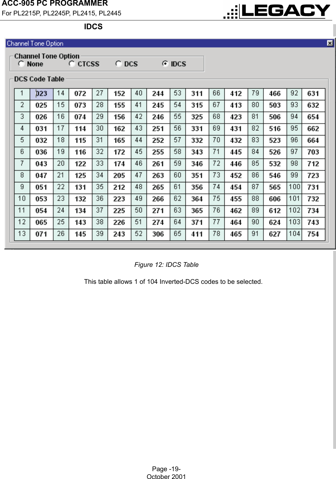
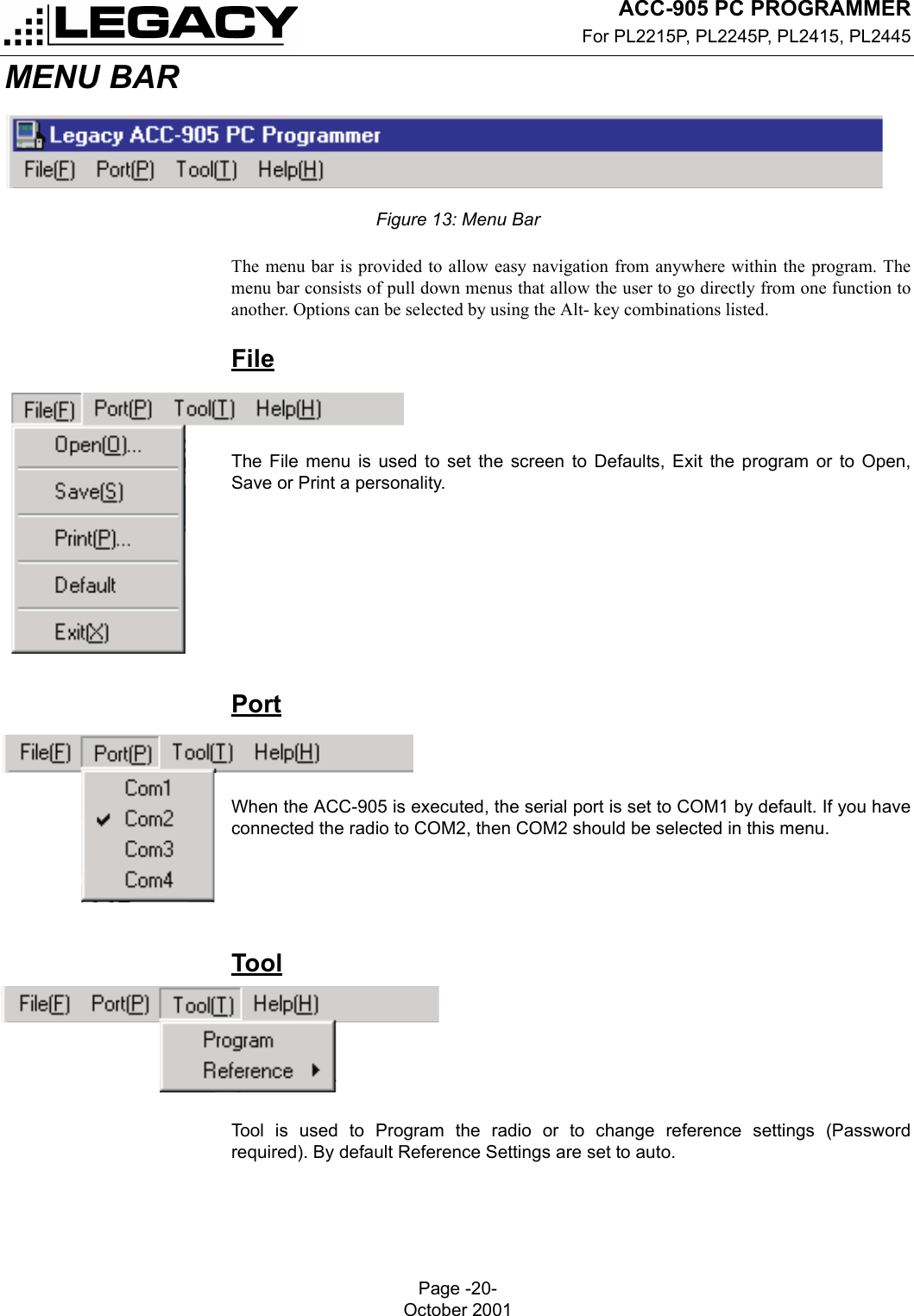
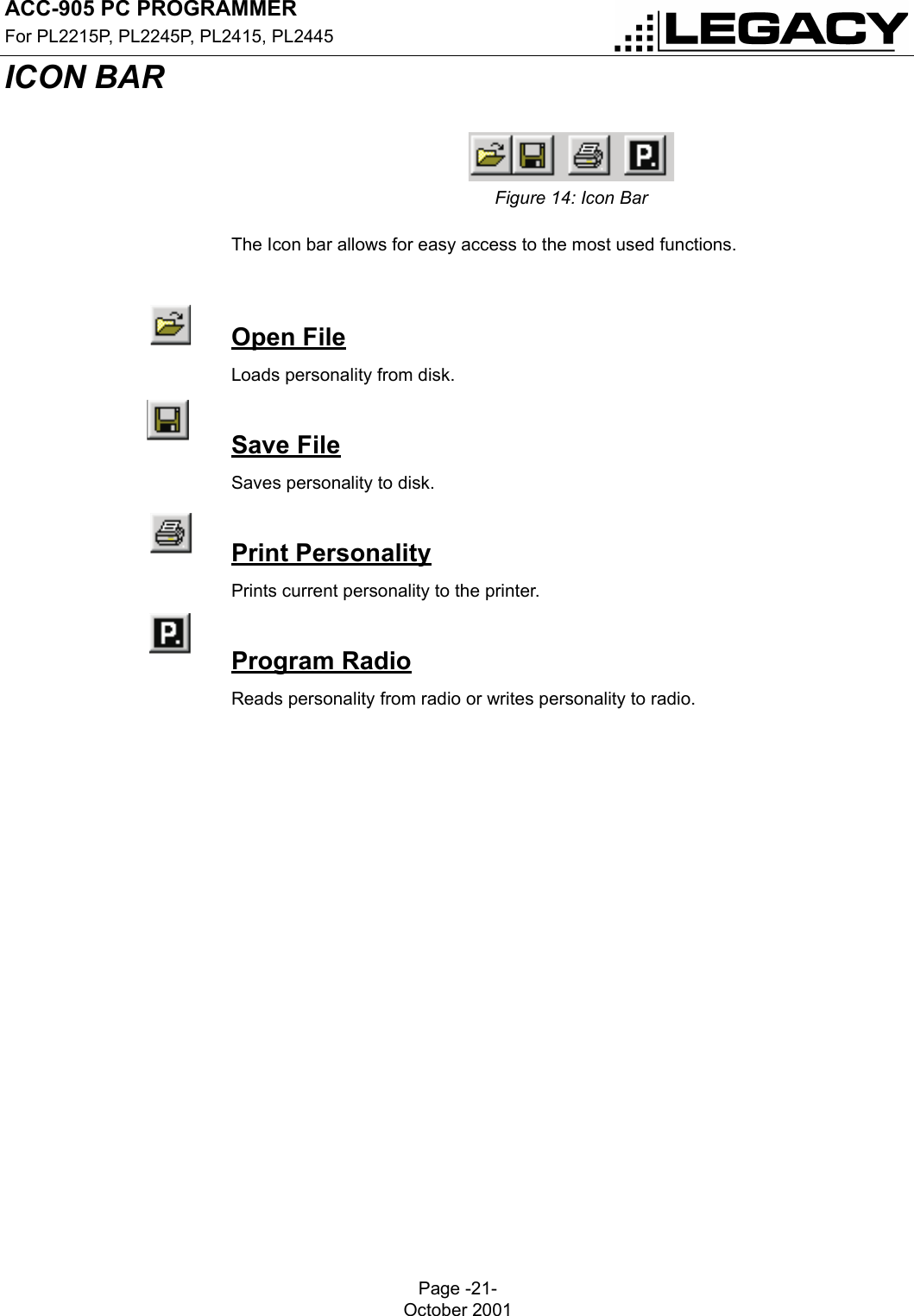
Programming manual
3.
manual
4.
USERS MANUAL 1 OF 2
5.
USERS MANUAL 2 OF 2
Programming manual
Navigation menu
Upload a User Manual
Namespaces
Wiki Guide
HTML
PDF
Info
Views
User Manual
Discussion / Help
Navigation