Midland Radio SD225V2 DATA MODULE User Manual User s Guide
Midland Radio Corporation DATA MODULE User s Guide
UserManual.wiki
>
Midland Radio
>
SD225V2 User Manual
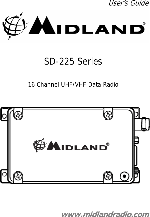
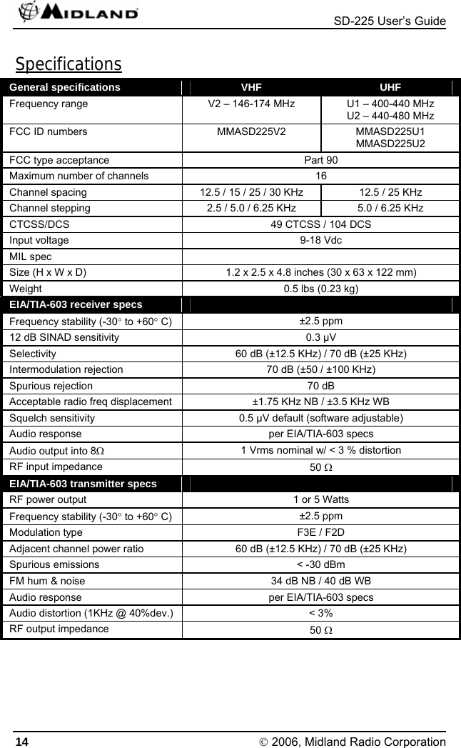
USERS GUIDE
Navigation menu
Upload a User Manual
Namespaces
Wiki Guide
HTML
PDF
Info
Views
User Manual
Discussion / Help
Navigation