Midland Radio SD225V2 DATA MODULE User Manual User s Guide
Midland Radio Corporation DATA MODULE User s Guide
USERS GUIDE

User’s Guide
SD-225 Series
16 Channel UHF/VHF Data Radio
www.midlandradio.com

SD-225 User’s Guide
2 © 2006, Midland Radio Corporation
FCC RF EXPOSURE COMPLIANCE REQUIREMENTS FOR
OCCUPATIONAL USE ONLY
The Federal Communications Commission (FCC), within
its action in General Docket 93-62, November 7, 1997,
has adopted a safety standard for human exposure to
Radio Frequency (RF) electromagnetic energy emitted
by FCC regulated equipment. Midland Radio Corporation
subscribes to the same safety standard for the use of its
products. Proper operation of this radio will result in user
exposure far below the Occupational Safety and Health
Act (OSHA) and FCC limits.
DO NOT transmit for more than 50% of total use
time (50% duty cycle). Transmitting more than
50% of the time can cause FCC RF exposure
compliance requirements to be exceeded.
This radio is NOT approved for use by the
general population in an uncontrolled
environment. This radio is restricted to
occupational use, work related operations only,
where the radio operator must have the
knowledge to control the user’s exposure
conditions for satisfying the higher exposure
limit allowed for occupational use.
The antenna used with this radio should not have
gain of more than 6 dBi. Make sure no one is
closer than 20 inches to the antenna when
transmitting. The radio is transmitting when the
red LED on the cover of the radio is illuminated.
You can cause the radio to transmit by grounding
pin 3 on the radio connector.
These are required operating conditions for
meeting FCC RF exposure compliance. Failure to
observe these restrictions means violation.

SD-225 User’s Guide
Contents
Conventions and Symbols in this Book ................................... 4
Disclaimer ................................................................................ 4
Safety....................................................................................... 4
Introduction .............................................................................. 6
Radio Models ....................................................................... 6
Radio Features..................................................................... 6
Recommended Accessories and Options............................ 7
Radio Connections................................................................... 8
Connection Overview ........................................................... 8
External Interface ............................................................... 10
DB9 Radio Interface Connector Details ............................. 10
Setup and Operation.............................................................. 12
Mounting............................................................................. 12
Channel Selection .............................................................. 12
Status LED ......................................................................... 13
Specifications......................................................................... 14
Warranty Statement............................................................... 15
© 2006, Midland Radio Corporation 3

SD-225 User’s Guide
Conventions and Symbols in this Book
This symbol marks a “caution”. Cautions are special notices
which you should read and follow carefully to avoid possible
damage to your equipment and to avoid potential danger to
yourself or other people.
! This symbol marks an “important point”. Important points are
specific instructions which should be followed closely for proper
operation.
This symbol marks a “note”. Notes are hints or tips which offer
additional information to help you.
Disclaimer
Midland Radio Corporation is committed to continuous quality
improvements, for this reason specifications may change without
prior notice.
Every effort has been made to ensure that the information in this
document is complete, accurate, and up-to-date. Midland
assumes no responsibility for the results of errors beyond its
control. The manufacturer of this equipment also cannot
guarantee that changes in the equipment made by unauthorized
people will not affect the transceiver’s performance or functions.
Safety
Your SD-225 data radio has been carefully designed to give you
years of safe, reliable performance. As with all electrical
equipment, however, there are a few basic precautions you
should take to avoid injury to yourself or damage to the radio:
Read the instructions in this book carefully. Be sure to save it for
future reference.
Read and follow all warning and instruction labels on the radio
itself.
Do not operate the radio near unshielded electrical blasting caps
or in an explosive atmosphere.
4 © 2006, Midland Radio Corporation

SD-225 User’s Guide
Do not operate the transmitter of any radio unless all RF
connectors are secure.
All equipment must be properly grounded for safe operation.
Do not allow children to operate or play with or near the radio
equipment.
Never attempt to service the radio yourself. All equipment should be
serviced by a qualified technician. Contact you local dealer or
communications coordinator for assistance.
Do not allow the antenna to touch or come in very close proximity
with the eyes, face, or any exposed body parts while the radio is
transmitting.
The above warning list is not intended to include all hazards that may
be encountered when using this radio.
© 2006, Midland Radio Corporation 5

SD-225 User’s Guide
Introduction
Congratulations! By choosing the Midland SD-225 data radio,
you have selected a flexible, easily configured communication
device. Its rugged design will provide years of reliable service
and exceptional performance.
Radio Models
The SD-225 data radio is available in three frequency ranges.
SD-225V2: 5 W, VHF high band, 148-174 MHz
SD-225U1: 5 W, UHF high band, 400-440 MHz
SD-225U2: 5 W, UHF high band, 440-480 MHz
Radio Features
The SD-225 series data radio is a programmable, synthesized
16 channel radio featuring:
5 Compact, rugged die cast enclosure.
5 Tri-color LED for operating, warning and programming status
indications.
5 9-18 Vdc supply voltage operating range.
5 5 Watts transmit power. A low power selection (1 Watt) may be chosen
if full power is not needed.
5 12.5 KHz and 25 KHz channel spacing, programmable per channel.
5 49 CTCSS tones / 104 DCS codes available, programmable per
channel.
5 Software adjusted noise squelch level. The squelch opening and closing
levels may easily be set using the programming software and an RF
signal generator.
5 External modem / direct FM modulation input.
5 Bell 202 / V.23 internal 1200 baud modem option.
5 Busy channel lockout feature may be programmed. An override function
for matched sub-audible is available to allow transmission during
repeater hangtime.
6 © 2006, Midland Radio Corporation

SD-225 User’s Guide
5 Transmit time-out timer may be programmed to limit continuous
transmission time.
5 Transmit hang timer may be programmed to keep the transmitter active
for a short time after the PTT signal is removed..
5 Basic radio controls (transmit mode, receive mode, channel change,
and modem test) are available via serial commands.
Recommended Accessories and Options
Software
ACC-917 PC programming and adjustment software
Cables
ACC-2025 USB PC programming cable
Options
ACC-512? Bell 202/V.23 internal 1200 baud modem
© 2006, Midland Radio Corporation 7

SD-225 User’s Guide
Radio Connections
Connection Overview
The SD-225 features two standard interfaces. The data interface
is used for connection to external modems and provides flat,
unfiltered input and output. The audio interface is used for voice
and some voiceband (300 – 3000 Hz) signaling applications.
If the internal modem option is installed, the data
interface may be configured for direct asynchronous
RS232 data input and output. PTT and Busy may also
be configured for RS232 levels. More information using
the internal modem is available in the modem manual.
Once the interface type is selected, the appropriate connections
may be chosen based on the information given below.
Power Connection
The SD-225 needs a stable 12V DC power source, capable of
supplying at least 2 amps of current. The power connections
should be made to DB9 pins 4 (-) and 5 (+).
The nominal input voltage for the SD-225 is 12 Vdc, but
it is capable of operating in a 9-18 Vdc range.
PTT Connection
A connection to the PTT input, DB9 pin 3, is required to put the
SD-225 into transmit mode. Switching the PTT input to 0V will
initiate transmit mode. With the internal modem option, the PTT
input may be changed to RS232 level.
Busy Connection
A connection may be made to the BUSY_DET output, DB9 pin 6,
which indicates the receive status of the SD-225. Pin 6 is
normally +5Vdc and switches to 0V when a signal exceeding the
programmed squelch threshold is received. If CTCSS/DCS is
programmed on the channel, the CTCSS/DCS must also be
8 © 2006, Midland Radio Corporation

SD-225 User’s Guide
decoded, before pin 6 will switch low. With the internal modem
option, the BUSY output may be changed to RS232 level.
Modulation Input Connections
The two choices for modulation are DATA_IN, DB9 pin 1 or
MIC_IN, DB9 pin 7. When the SD-225 is used in low speed data
applications (with an external modem), the modem data to be
transmitted is usually connected to pin 1. The SD-225 connects
the pin 1 input to the transmitter by default.
For audio applications, the transmit audio is usually connected to
pin 7. The SD-225 must detect a load on pin 7, before it will
switch pin 7 into the transmit circuit. This load could be a
microphone element that is switched into the circuit by PTT.
Alternatively, a 10K resistor may be connected from PTT (pin
3) to MIC_IN (pin 7). This will load pin 7 when transmitting.
Pin 7 has a second function in receive mode. If this pin is
switched low in receive mode the SD-225 will enter
monitor mode (open squelch). The MIC_IN load should
only be in the circuit during transmit mode. It may be
necessary to use an A/C coupling capacitor from the
external modulation source to prevent the SD-225 from
entering monitor mode.
Demodulated Output Connections
The demodulated output from the receiver is available on
DATA_OUT, DB9 pin 2 and SPK_OUT, DB9 pin 9. For low
speed data applications, the flat, discriminator output, pin 2, is
usually connected to the external modem. Pin 2 will provide 200-
300 mVrms into a 10K load when receiving a 1 KHz audio
signal modulated at 60%.
For audio applications, the bandpass filtered (300 – 3000 Hz)
and de-emphasized audio available on pin 9 is typically used.
Pin 9 is adjusted for a nominal 1 Vrms into an 8 load, when
receiving a 1 KHz audio signal modulated at 60%. RV403 may
be used to adjust the pin 9 output level.
© 2006, Midland Radio Corporation 9
SD-225 User’s Guide
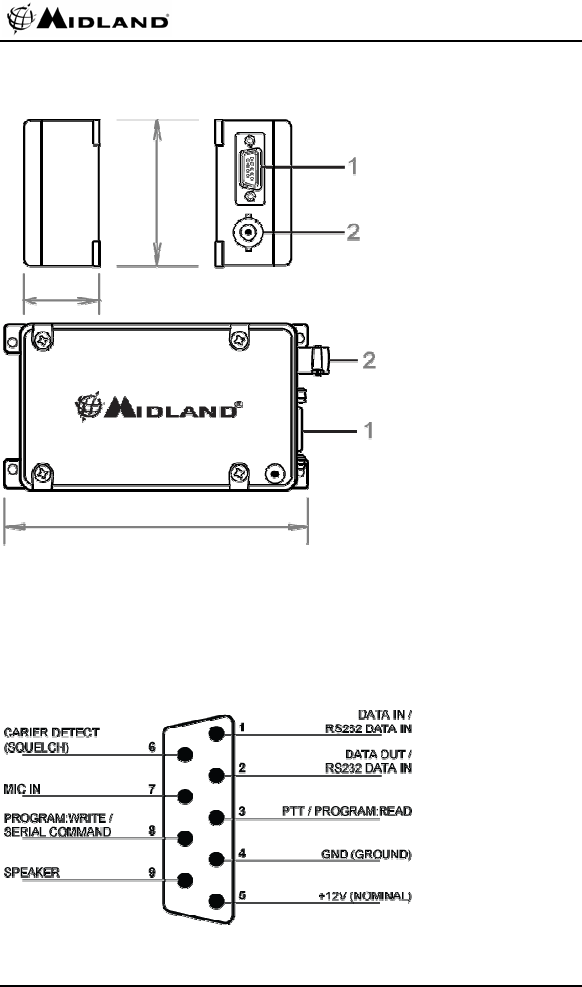
External Interface
2.5 in
1.2 in
4.6 in
1. DB9 male: modulation input, demodulation output, control inputs and power
supply.
2. BNC female: antenna connection.
DB9 Radio Interface Connector Details
10 © 2006, Midland Radio Corporation
SD-225 User’s Guide
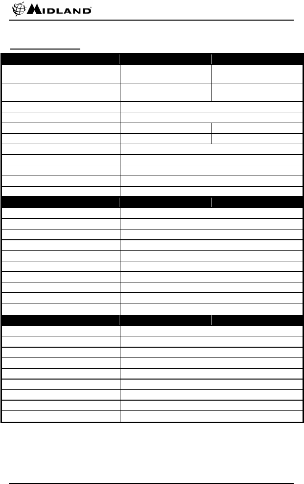
Pin No. Name/Function Description Signal Type
1
(default)
DATA_IN
Data modulation input
LK409 in, LK412 out:
A/C coupled signal to modulator through
the data low pass filter, without pre-
emphasis.
Analog signal
100-120 mVrms of
1KHz audio for 60%
deviation
1
(alternate)
DATA_IN
RS232 data input
LK409 out, LK412 in:
Asynchronous data input to Bell 202/V.23
modem option. See modem manual.
RS232 level
2
(default)
DATA_OUT
Data demodulation
output
LK413 in, LK414 out:
Buffered, unfiltered discriminator audio
output.
Analog signal
1KHz audio @ 60%
deviation produces
200-300 mVrms
2
(alternate)
DATA_OUT
RS232 data output
LK413 out, LK414 in:
Asynchronous data output from Bell
202/V.23 modem option. See modem
manual.
RS232 level
3
(default)
PTT/PROG_READ
PTT input (Program
read)
Active low input which keys the
transmitter.
Also used for program data output during
read mode.
TTL level
0V = TX
3
(alternate)
PTT/PROG_READ
PTT key input
CON407 configured for RS232 PTT:
PTT input to modem option. See modem
manual.
RS232 level
+12V = TX
-12V = RX
4 GND
Ground
Ground connection to chassis of the
radio.
5 B+
DC supply input
Power connection. 9-18Vdc, 12Vdc
nominal
6
(default)
BUSY_DET
Busy detect output
Active low output to indicate presence of
carrier, or carrier + CTCSS/DCS.
TTL level
0V = carrier
6
(alternate)
BUSY_DET
Busy detect output
CON407 configured for RS232 Busy:
Carrier detect output from modem option.
See modem manual.
RS-232 level
+12V = carrier
-12V = no carrier
7 MIC_IN
Microphone (audio)
modulation input
A/C coupled audio signal to the
modulator through 300 Hz high pass
filter, pre-emphasis and data low pass
filter. Sub-audible tone is mixed with the
audio after the data filter.
Also used for monitor function. If this
input is pulled low in RX, the radio will
enter monitor mode (open squelch).
Analog signal
6-8mVrms of 1KHz
audio for 60%
deviation
0V = Monitor
8 PROG_WRITE
Programming data
input (serial control
input)
Data input used during read/write
programming mode.
Also used for serial control data input.
TTL level (Level
converter required
for RS232
connection)
9 SPK_OUT
Speaker (audio)
demodulation output
Filtered and de-emphasized audio output. Analog signal
1KHz audio @ 60%
deviation produces
nominal 1Vrms into
8
© 2006, Midland Radio Corporation 11
SD-225 User’s Guide
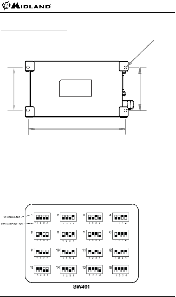
Setup and Operation
Mounting D=0.14 in
1.93 in
2.01 in
The SD-225 data radio should be secured to the mounting
surface or bracket using suitable screws through the four
mounting flanges. The mounting hole center to center
dimensions are shown above.
4.33 in
The RF cabling should be routed separately from the control
cabling to avoid interference.
Channel Selection
12 © 2006, Midland Radio Corporation
SD-225 User’s Guide
The normal operating channel should be selected using the
internal DIP switch, SW401. The radio channel may also be
selected by serial commands, but the radio will always power up
on the channel selected by the DIP switch.
1. Remove the four screws securing the top cover and remove the top cover.
2. Set the DIP switch for binary channel selection according to the chart
above, i.e. channel 1 is all switches off, channel 16 is all switches on.
3. Replace the top cover and secure with the four screws.
Status LED
The LED on the top cover indicates the status of the data radio.
If a speaker has been connected to pin 9 of the radio interface
connector, audible tones can be heard indicating certain
conditions.
Radio Mode Radio Status LED Indication Beep Indication
Power-on GreenÆorangeÆred
Busy channel Steady orange
Busy channel w/correct
CTCSS/DCS
Steady green
Normal
Operation
Transmit Steady red
Busy channel lockout Continuous green flash
when PTT activated
Continuous beep
Time out timer expired Continuous green flash
while transmitting
5 sec before time out timer expires One green flash Single beep
Subaudible disabled for data input Two green flashes then
red when PTT active
EEPROM error One orange flash
Out of lock Four yellow flashes
Communication error with modem
MCU
Continuous green flash
Warning
Transmit hang time Continued steady red
when PTT released
Program read Continuous red flash Program
Program write Continuous green flash
Initial data load GreenÆorangeÆred
Open level set Three green flashes
Close level set Two green flashes
Squelch set
Squelch level save One green flash
© 2006, Midland Radio Corporation 13
SD-225 User’s Guide
Specifications
General specifications VHF UHF
Frequency range V2 – 146-174 MHz U1 – 400-440 MHz
U2 – 440-480 MHz
FCC ID numbers MMASD225V2 MMASD225U1
MMASD225U2
FCC type acceptance Part 90
Maximum number of channels 16
Channel spacing 12.5 / 15 / 25 / 30 KHz 12.5 / 25 KHz
Channel stepping 2.5 / 5.0 / 6.25 KHz 5.0 / 6.25 KHz
CTCSS/DCS 49 CTCSS / 104 DCS
Input voltage 9-18 Vdc
MIL spec
Size (H x W x D) 1.2 x 2.5 x 4.8 inches (30 x 63 x 122 mm)
Weight 0.5 lbs (0.23 kg)
EIA/TIA-603 receiver specs
Frequency stability (-30° to +60° C) ±2.5 ppm
12 dB SINAD sensitivity 0.3 µV
Selectivity 60 dB (±12.5 KHz) / 70 dB (±25 KHz)
Intermodulation rejection 70 dB (±50 / ±100 KHz)
Spurious rejection 70 dB
Acceptable radio freq displacement ±1.75 KHz NB / ±3.5 KHz WB
Squelch sensitivity 0.5 µV default (software adjustable)
Audio response per EIA/TIA-603 specs
Audio output into 8Ω 1 Vrms nominal w/ < 3 % distortion
RF input impedance 50 Ω
EIA/TIA-603 transmitter specs
RF power output 1 or 5 Watts
Frequency stability (-30° to +60° C) ±2.5 ppm
Modulation type F3E / F2D
Adjacent channel power ratio 60 dB (±12.5 KHz) / 70 dB (±25 KHz)
Spurious emissions < -30 dBm
FM hum & noise 34 dB NB / 40 dB WB
Audio response per EIA/TIA-603 specs
Audio distortion (1KHz @ 40%dev.) < 3%
RF output impedance 50 Ω
14 © 2006, Midland Radio Corporation

SD-225 User’s Guide
Warranty Statement
Midland Radio Corporation (herein, Midland) warrants each new radio product manufactured
or supplied by it to be free from defects in material and workmanship under normal use and
service for a period listed below, provided that the user has complied with the requirements
stated herein.
The Warranty period begins on the date of purchase from an Authorized Midland Sales and
Service Outlet. This Warranty is offered to the original end user and is not assignable or
transferable. Midland is not responsible for any ancillary equipment attached to or used in
conjunction with Midland products.
Midland offers to the original end user a Two (2) Year Limited Warranty on Midland Business
and Industrial radio products. Accessories carry a One (1) Year Limited Warranty.
During this period, if the product fails to function under normal use because of manufacturing
defect(s) or workmanship, it should be returned to the Authorized Midland Sales and Service
Outlet from which it was purchased. The Sales and Service Outlet will repair the product or
return the product for repair to Midland or its Authorized Repair Depot. The user is
responsible for the payment of any charges or expenses incurred for the removal of the
defective product from the vehicle or other site of its use; for the transportation of the product
to the Sales and Service Outlet; for the return of the repaired / replacement product to the
site of its use and for the reinstallation of the product.
Midland shall have no obligation to make repairs or to cause replacement required, which
results from normal wear and tear or is necessitated in whole or in part by catastrophe, fault
or negligence of the user, improper or unauthorized alterations or repairs to the Product,
incorrect wiring, use of the Product in a manner for which it was not designed or by causes
external to the Product. This Warranty is void if the product serial number is altered, defaced
or removed.
Midland’s sole obligation hereunder shall be to replace or repair the Product covered in this
Warranty. Replacement, at Midland’s option, may include a similar or higher-featured
product. Repair may include the replacement of parts or boards with functionally equivalent
reconditioned or new parts or boards. Replaced parts, accessories, batteries or boards are
warranted for the balance of the original time period. All replaced parts, accessories,
batteries or boards become the property of Midland.
THE EXPRESS WARRANTIES CONTAINED HEREIN ARE IN LIEU OF ALL OTHER
WARRANTIES, EITHER EXPRESSED OR IMPLIED OR STATUTORY, INCLUDING,
WITHOUT LIMITATION, ANY WARRANTY OF MERCHANTABILITY OR FITNESS FOR A
PARTICULAR PURPOSE.
FOR ANY PRODUCT WHICH DOES NOT COMPLY WITH THE WARRANTY SPECIFIED,
THE SOLE REMEDY WILL BE REPAIR OR REPLACEMENT. IN NO EVENT WILL
MIDLAND BE LIABLE TO THE BUYER OR ITS CUSTOMERS FOR ANY DAMAGES,
INCLUDING ANY SPECIAL, INCIDENTAL, INDIRECT OR CONSEQUENTIAL DAMAGES,
OR FOR THE LOSS OF PROFIT, REVENUE OR DATA ARISING OUT OF THE USE OF
OR THE INABILITY TO USE THE PRODUCT.
This warranty is void for sales and deliveries outside of the U. S. A. and Canada.
© 2006, Midland Radio Corporation 15

This device complies with Part 15 of the FCC Rules. Operation is
subject to the condition that this device does not cause harmful
interference.
This radio operates in FCC regulated frequency bands. All radios
must be licensed by the FCC before use. Because this radio
contains a transmitter, Federal law prohibits unauthorized use or
adjustments of this radio.
5900 PARRETTA DRIVE, KANSAS CITY, MISSOURI, 64120
PHONE: (816) 241-8500, FAX: (816) 241-5713
www.midlandradio.com
October 2006