Midmark RTLS Solutions VER1650 RF ID Badge Transmitter User Manual Complete Versus hardware installation manual
Versus Technology, Inc. RF ID Badge Transmitter Complete Versus hardware installation manual
Contents
- 1. First 2 pages of hardware manual with FCC statement
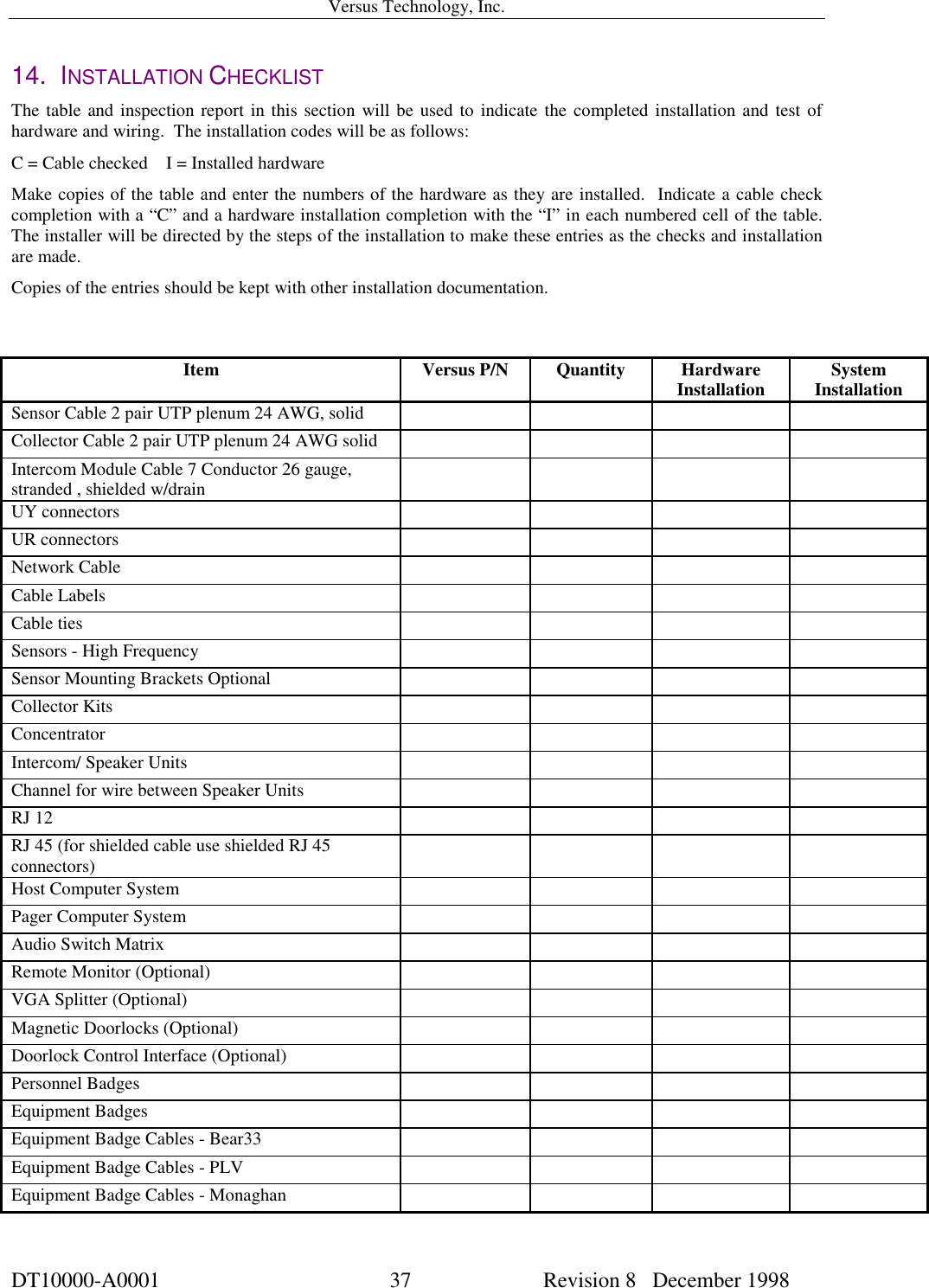
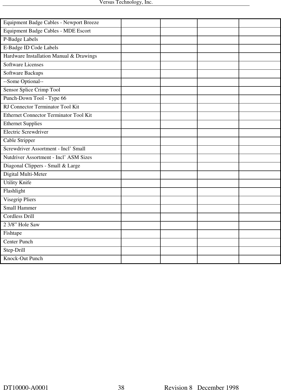
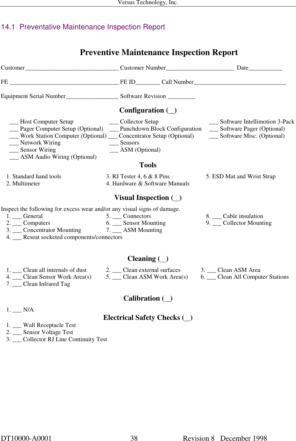
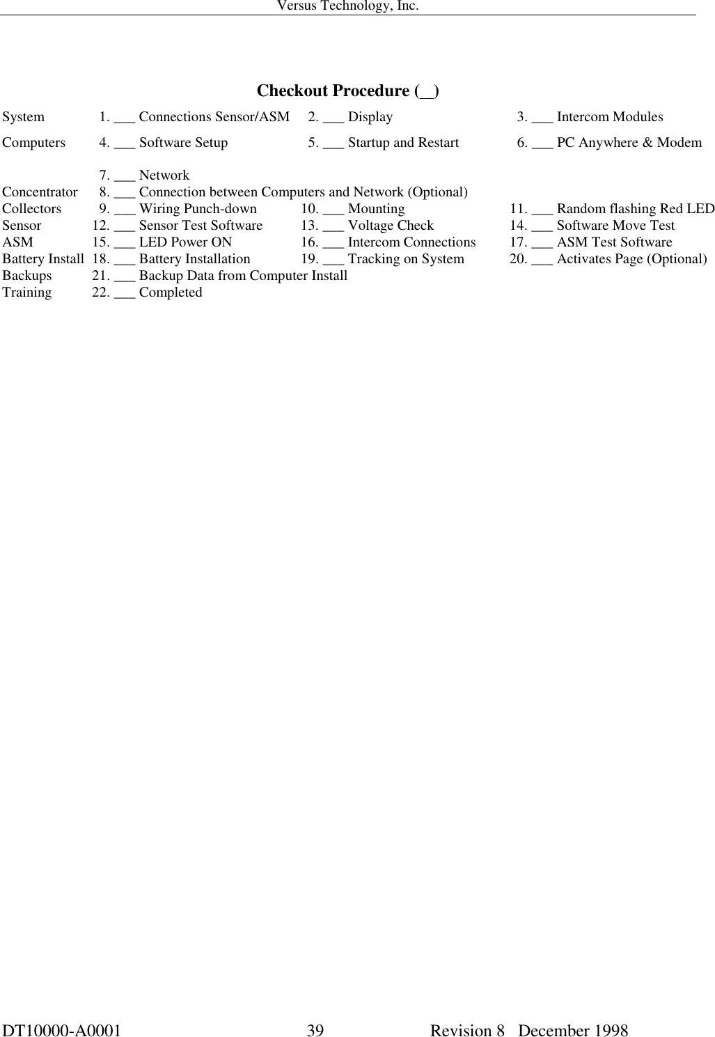
- 2. Complete Versus hardware installation manual
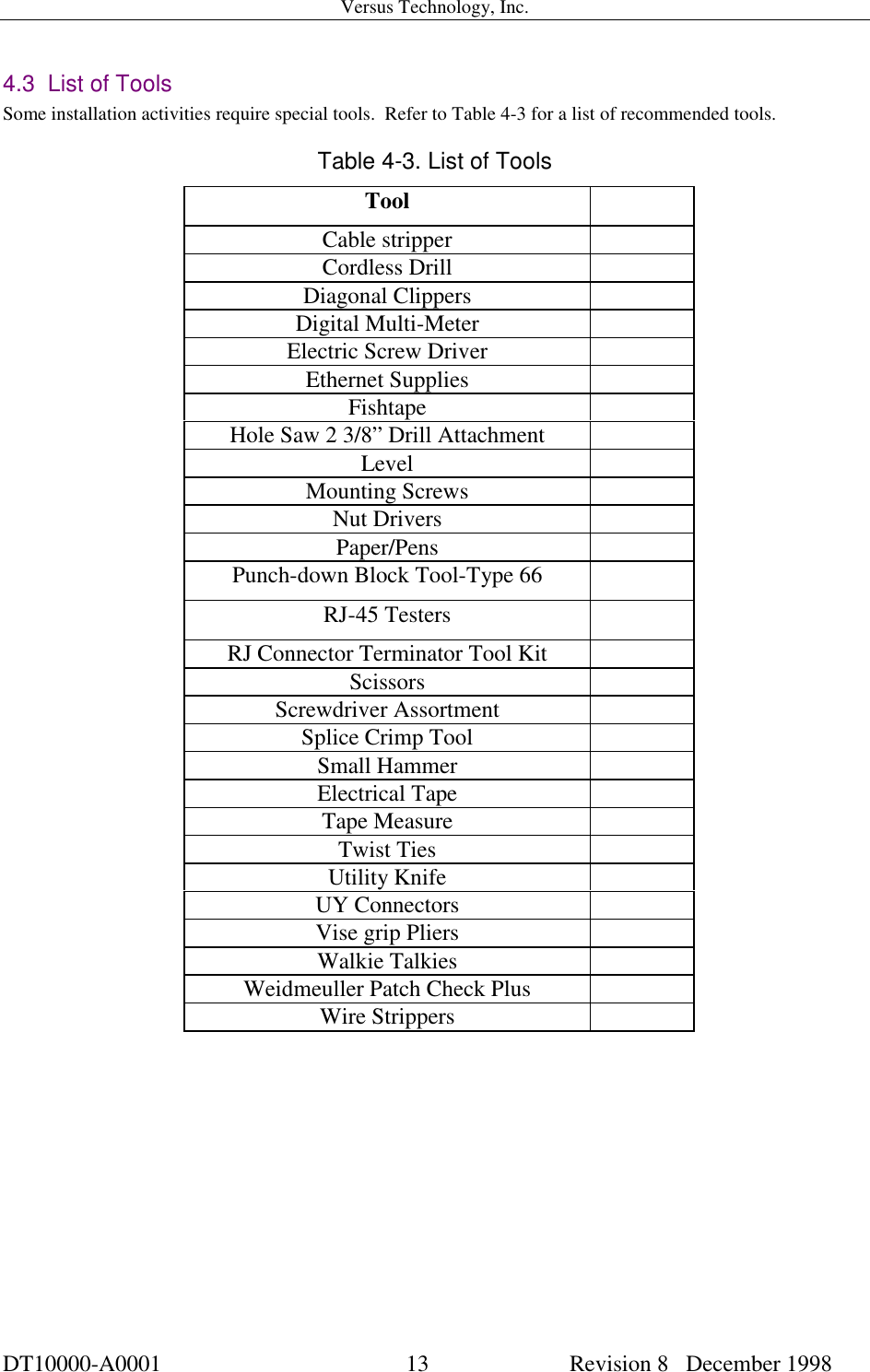
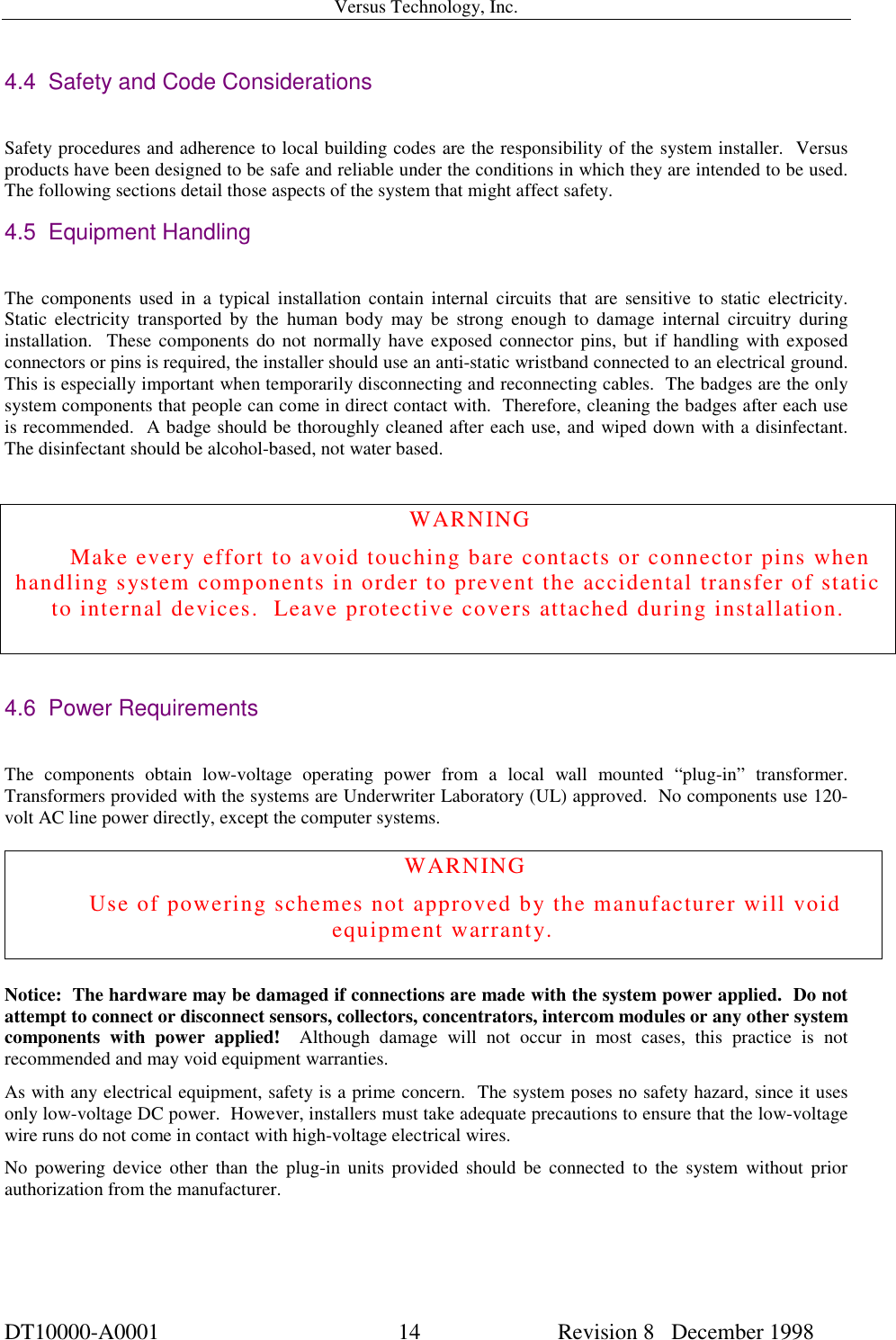
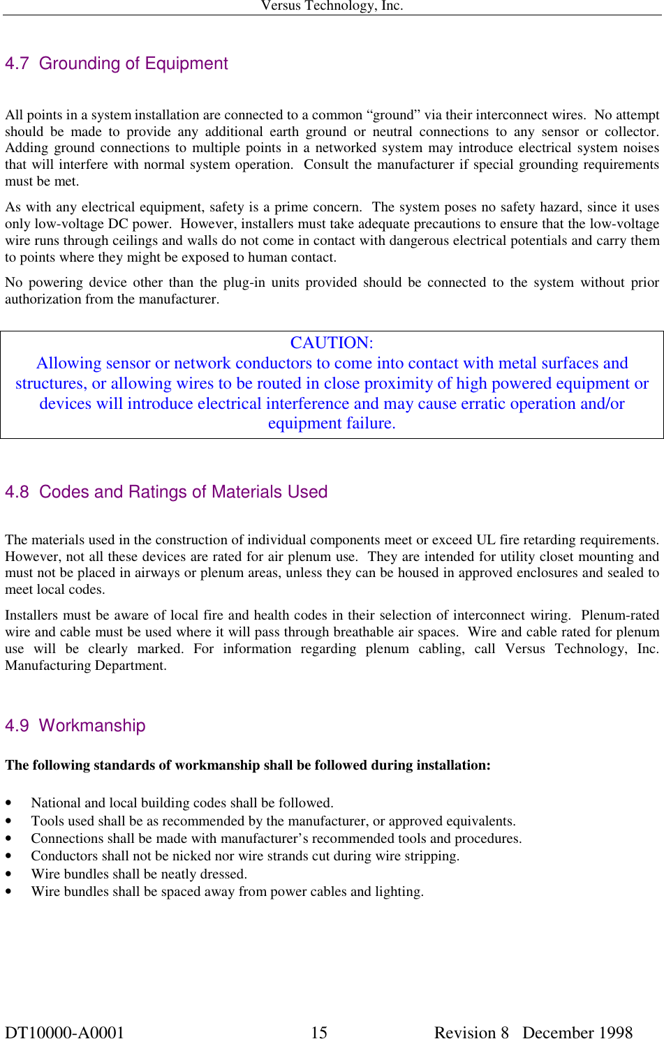
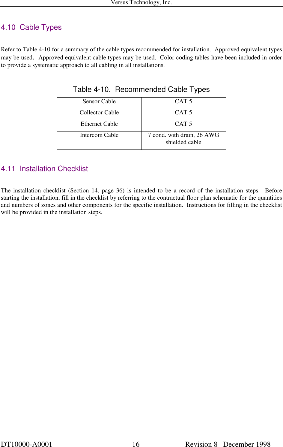
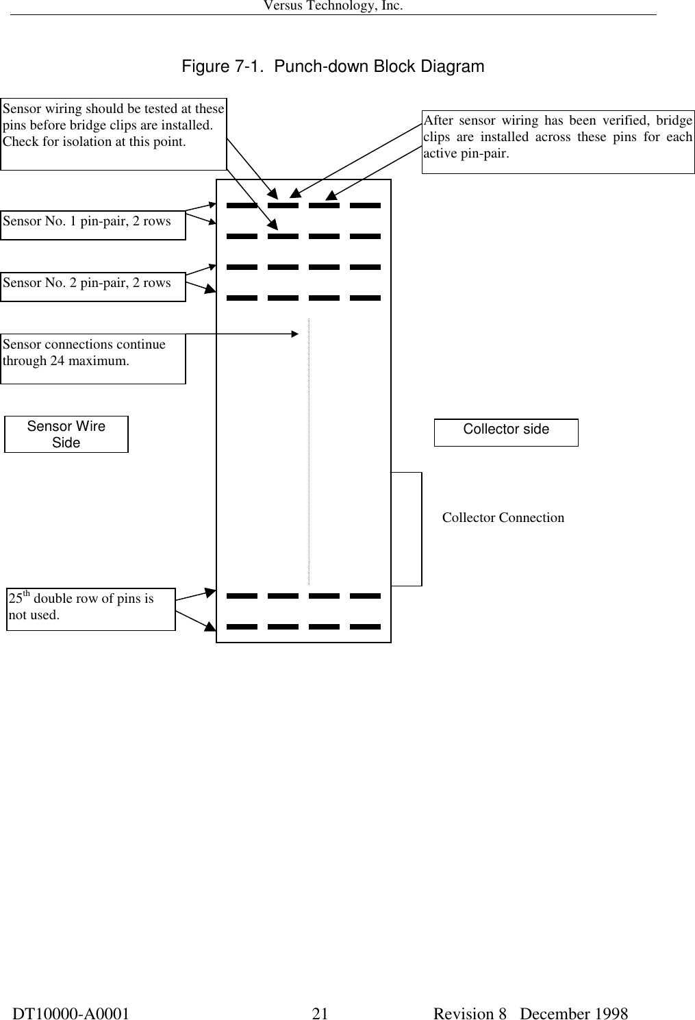
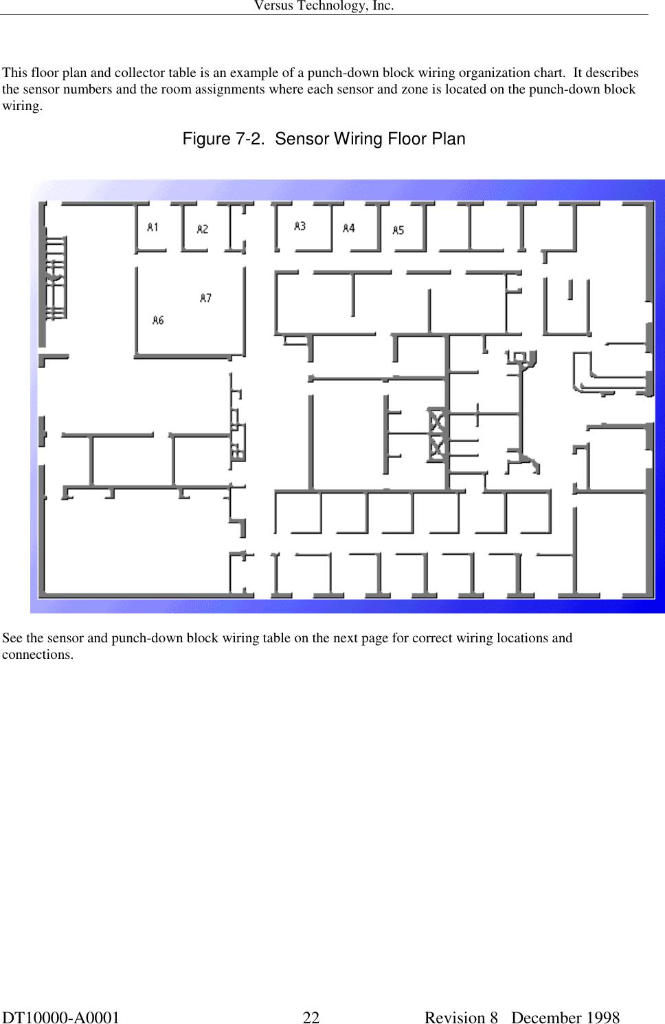
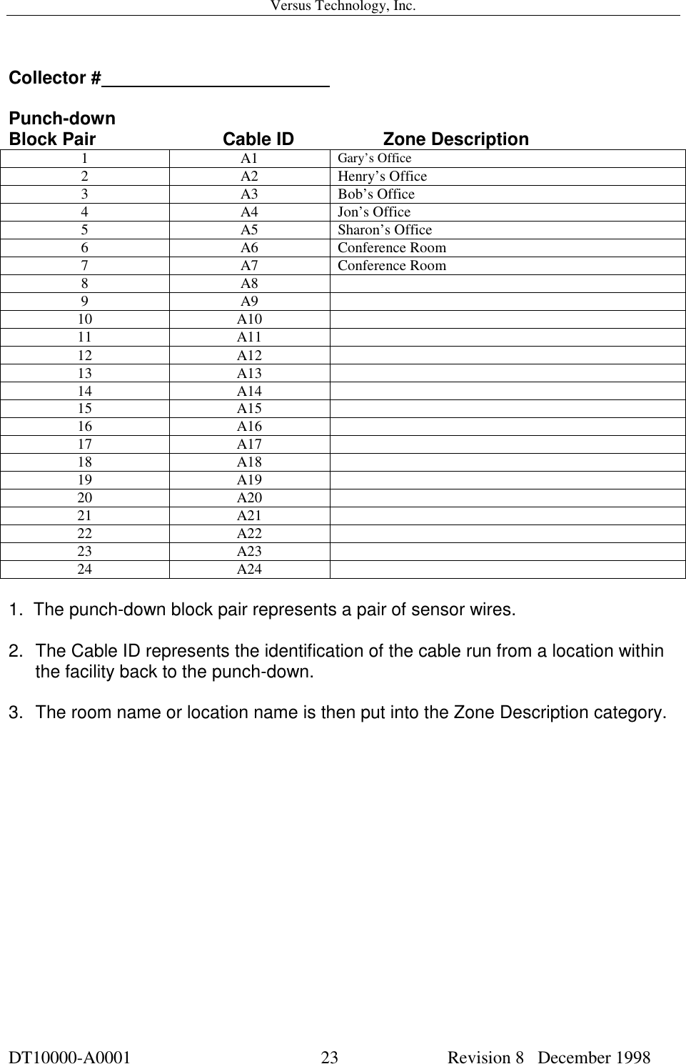
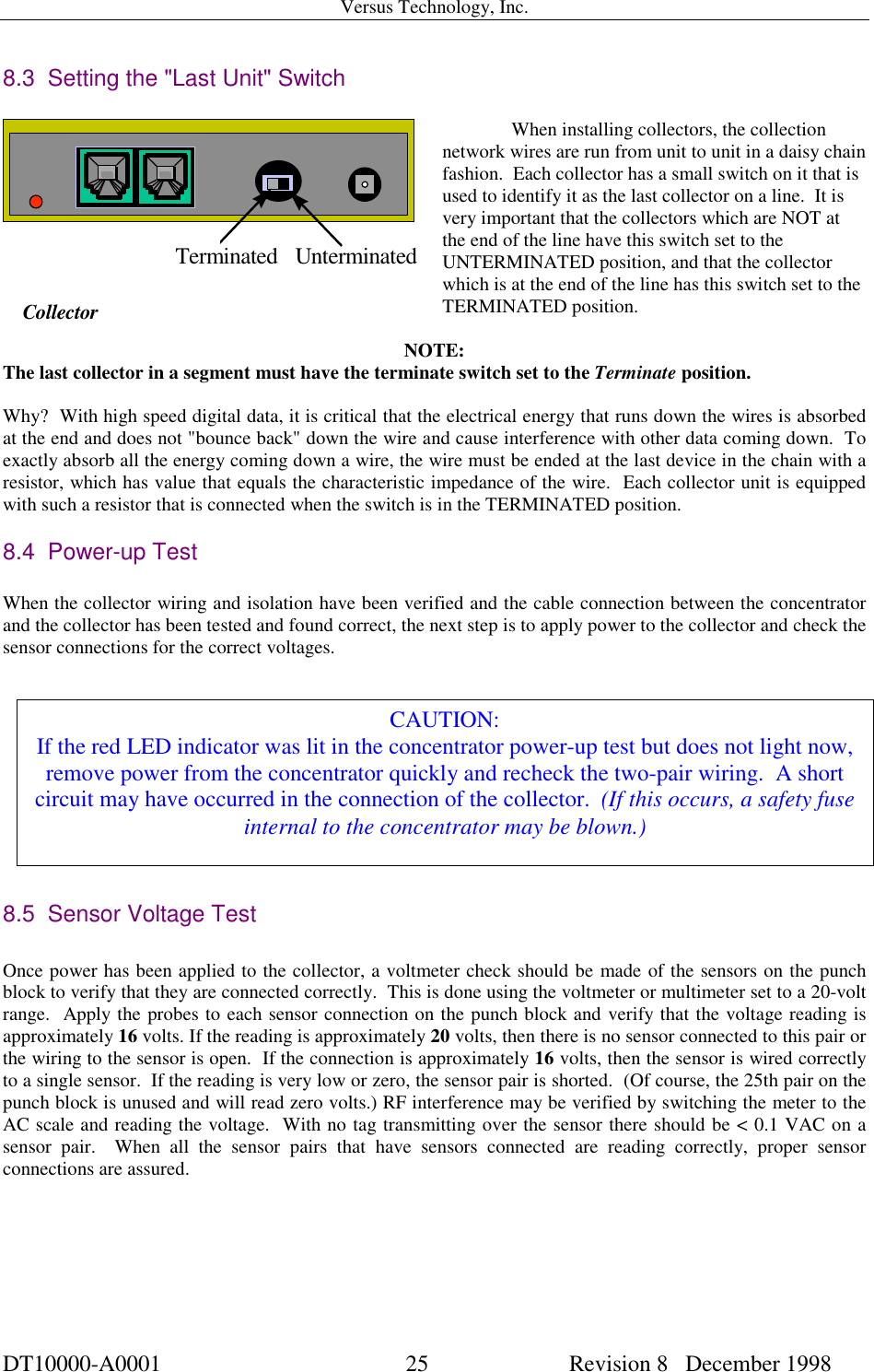
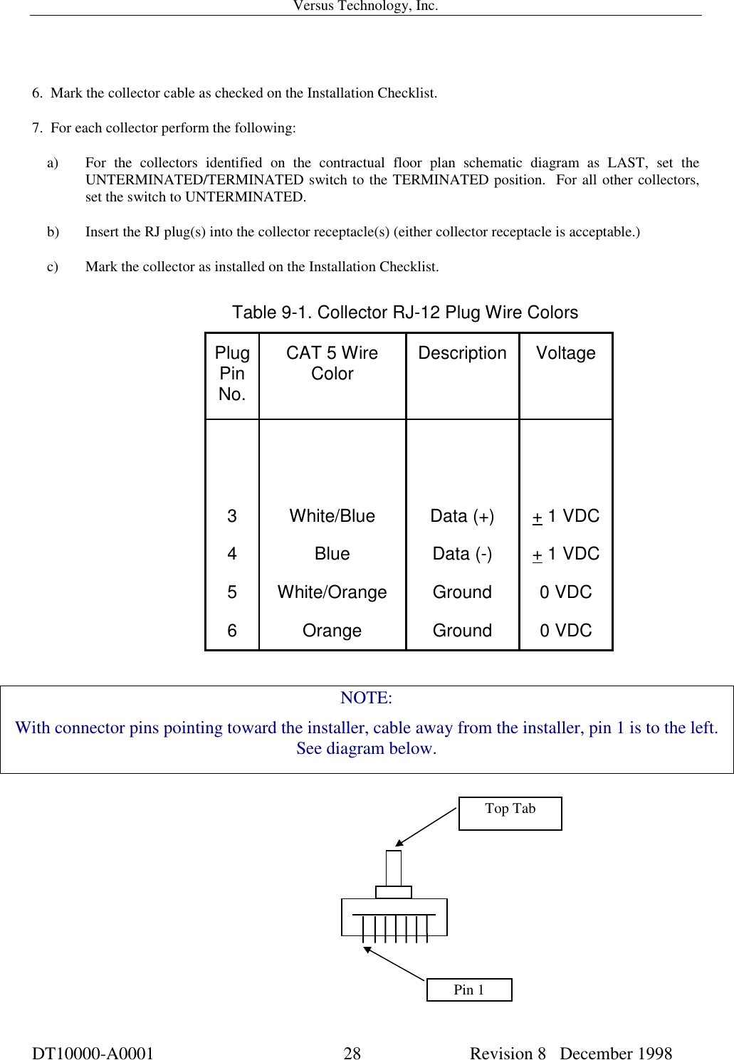
Complete Versus hardware installation manual