Midmark RTLS Solutions VER1650 RF ID Badge Transmitter User Manual Complete Versus hardware installation manual
Versus Technology, Inc. RF ID Badge Transmitter Complete Versus hardware installation manual
Contents
- 1. First 2 pages of hardware manual with FCC statement
- 2. Complete Versus hardware installation manual
Complete Versus hardware installation manual

Versus Technology, Inc.
DT10000-A0001 i Revision 8 December 1998
Hardware/Wiring Installation Guide
VERSUS TECHNOLOGY, INC.
2600 MILLER CREEK ROAD
TRAVERSE CITY, MI 49684
(616) 946-5868

Versus Technology, Inc.
DT10000-A0001 ii Revision 8 December 1998
Copyright 1991, 1992, 1993, 1996, and 1998 Versus Technology, Inc., all rights reserved
This document contains user’s information on technology that is proprietary to Versus Technology, Inc.
Permitted transmittal, receipt, or possession of this document does not express license or imply any rights
to use, sell, design, or manufacture this information. No reproduction, publication or disclosure of this
information, in whole or in part, shall be made without prior written authorization from an officer of
Versus Technology, Inc.
To Clean Badges: wipe gently with damp cloth. WARNING! This product is not designed, intended,
authorized or warranted for use in any life support or other application where product failure could cause or
contribute to personal injury, death, or severe property damage. This component or its systems are covered
by one or more of the following U.S. Patents: 5,276,496, 5,355,222; 5,119,104; 5,548,637; 5,572,195;
5,387,993; 5,027,314, 5,017,794, 4,906,853.
FCC STATEMENT: Components VER-1650 and VER-4450 comply with part 15 of the FCC Rules. Operation is
subject to the following two conditions: 1) This device may not cause harmful interference, and 2) this device must
accept any interference received, including interference that may cause undesired operation.

Versus Technology, Inc.
DT10000-A0001 iii Revision 8 December 1998
Table of Revisions
Rev Date Description Initials Authorized
By:
13/7/96 Initial Release. RAV
25/1/96 Added Eagle speaker connections; Modified tbl. 1-1, fig. 2-1 and
2-2. RAV
-- Multiple comments from reviews. Modified tbl. 3-1, 4-1, and 4-2;
Added figs. 4-3, 4-5, tbl.4-3, para. 3.10, 3.11, 4.1.5 RAV
38/1/96 Changed system name. RAV
4Complete update to cover new high frequency equipment DAD
54/2/98 Complete Update/Revision of Hardware Manual to current
specifications and displays. EPD
66/17/98 Updated/Changed hardware specifications to current procedures.
Added Tech Support section. Added Wire Run Check-off Diagram
to manual. Changed Manual Cover Page to reflect products.
EPD
7Nov. 1998 Changed collector network length diagram to represent a six
collector to one concentrator specification (figure 3-2). Added to
hardware section 1.4 for a display of important system components.
Added to table 12-1 to include current part numbers to parts added.
EPD
8Dec. 1998 Added Troubleshooting Flow Charts to section 13, for possible
solutions for system hardware problems. Added Figure 7-2. Sensor
Wiring Floor plan. Added Battery Replacement table Section 2.4
EPD
93/11/99 Added FCC compliance statements for IR/RF Badge and RF Sensor SKB

Versus Technology, Inc.
DT10000-A0001 iv Revision 8 December 1998
Table of Contents
SECTION PAGE #
1. INTRODUCTION........................................................................................................................................................1
1.1 PURPOSE OF THIS GUIDE...........................................................................................................................................1
1.2 SCOPE OF USE...........................................................................................................................................................1
1.3 INSTALLATION SEQUENCE ........................................................................................................................................1
1.4 HARDWARE SPECIFICATIONS / SYSTEM COMPONENTS .............................................................................................2
1.5 COMPUTER SYSTEM REQUIREMENTS ........................................................................................................................2
1.6 TERMS AND DEFINITIONS..........................................................................................................................................2
2. SYSTEM HARDWARE DESCRIPTION..................................................................................................................5
2.1 GENERAL..................................................................................................................................................................5
2.2 INFRARED (IR) TRACKING........................................................................................................................................5
2.3 BADGES ....................................................................................................................................................................6
2.4 BATTERY REPLACEMENT..........................................................................................................................................6
3. PLANNING AND INSTALLATION GUIDELINES ...............................................................................................7
3.1 GENERAL..................................................................................................................................................................7
3.2 COLLECTOR NETWORK LENGTH LIMITATIONS..........................................................................................................8
3.3 SENSOR CONNECTION LENGTH LIMITATIONS ...........................................................................................................8
3.4 LOCATION OF COLLECTORS, AND CONCENTRATORS ................................................................................................8
3.5 SENSOR LOCATION PLANNING..................................................................................................................................9
3.6 UNDERSTANDING HIGH FREQUENCY SENSOR "FIELD-OF-VIEW"..............................................................................9
3.7 EFFECTIVE COVERAGE OF ROOMS ..........................................................................................................................10
3.8 SPECIAL PROBLEMS WITH SENSOR COVERAGE .......................................................................................................11
3.9 OVERLAPPING SENSORS..........................................................................................................................................11
3.10 HIGH FREQUENCY LIGHT INTERFERENCE .............................................................................................................11
3.11 USE OF UNAUTHORIZED COMPONENTS.................................................................................................................12
4. INSTALLATION GUIDELINES.............................................................................................................................12
4.1 GENERAL................................................................................................................................................................12
4.2 LIST OF MATERIALS................................................................................................................................................12
4.3 LIST OF TOOLS........................................................................................................................................................13
4.4 SAFETY AND CODE CONSIDERATIONS.....................................................................................................................14
4.5 EQUIPMENT HANDLING...........................................................................................................................................14
4.6 POWER REQUIREMENTS ..........................................................................................................................................14
4.7 GROUNDING OF EQUIPMENT ...................................................................................................................................15
4.8 CODES AND RATINGS OF MATERIALS USED............................................................................................................15
4.9 WORKMANSHIP.......................................................................................................................................................15
4.10 CABLE TYPES........................................................................................................................................................16
4.11 INSTALLATION CHECKLIST ...................................................................................................................................16
5. CABLE INSTALLATION ........................................................................................................................................17
5.1 CABLE INSTALLATION ............................................................................................................................................17
6. INSTALLING AND CHECKING SENSORS.........................................................................................................18
6.1 SENSOR WIRING......................................................................................................................................................18
6.2 SENSOR WIRING STEPS ...........................................................................................................................................18
7. PUNCH-DOWN BLOCK INSTALLATION AND ORGANIZATION................................................................20

Versus Technology, Inc.
DT10000-A0001 v Revision 8 December 1998
8. INSTALLING AND CHECKING COLLECTORS ...............................................................................................24
8.1 CHECKING THE COLLECTOR WIRING ......................................................................................................................24
8.2 CHECKING ISOLATION.............................................................................................................................................24
8.3 SETTING THE "LAST UNIT" SWITCH........................................................................................................................25
8.4 POWER-UP TEST......................................................................................................................................................25
8.5 SENSOR VOLTAGE TEST..........................................................................................................................................25
8.6 LOCAL POWERED COLLECTORS ..............................................................................................................................26
8.7 COLLECTOR NETWORK WIRING CONNECTIONS......................................................................................................26
9. COLLECTOR WIRING ...........................................................................................................................................27
9.1 COLLECTOR WIRING STEPS ....................................................................................................................................27
10. CONCENTRATOR INSTALLATION..................................................................................................................29
10.1 COMPUTER NETWORK CARD ................................................................................................................................29
10.2 INTERNAL CONCENTRATOR INSTALLATION ..........................................................................................................29
11. INSTALLING AND CHECKING THE EXTERNAL CONCENTRATOR ......................................................30
11.1 NETWORK WIRING FOR ARCNET AND ETHERNET CONCENTRATORS ....................................................................30
11.2 POWER-UP TEST....................................................................................................................................................30
12. HARDWARE COMPONENTS..............................................................................................................................32
13. TROUBLE SHOOTING GUIDE ...........................................................................................................................33
13.1 COLLECTOR VOLTAGE TROUBLESHOOTING FLOW CHART ...................................................................................35
13.2 FUNCTIONALITY TEST FLOW CHART ....................................................................................................................36
14. INSTALLATION CHECKLIST ............................................................................................................................37
14.1 PREVENTATIVE MAINTENANCE INSPECTION REPORT ...........................................................................................38

Versus Technology, Inc.
DT10000-A0001 vi Revision 8 December 1998
List of Figures
1. Figure 3-1. General Guidelines for Installations
2. Figure 3-2. Collector Network Length Limitations
3. Figure 7-1. Punch-down Block Diagram
4. Figure 7-2. Sensor Wiring Floor Plan
List of Tables
1. Table 4-3. List of Tools
2. Table 4-10. Recommended Cable Types
3. Table 9-1. Collector RJ-12 Plug Wire Colors
4. Table 12-1. Hardware Components

Versus Technology, Inc.
DT10000-A0001 1 Revision 8 December 1998
1. INTRODUCTION
1.1 Purpose of This Guide
This guide provides the information required to install the hardware and wiring. Read this entire document
before proceeding with the installation.
1.2 Scope of Use
This document is intended to provide the information required to install an IR system. A general understanding
of wiring and telephone installation techniques is assumed.
1.3 Installation Sequence
The installation procedures are generally organized as follows:
1. Provide a site visit to the facility
2. Run appropriate installation wires between hardware locations
3. Document wiring configuration
4. Install hardware components
5. Test hardware wiring
6. Installer sign-off

Versus Technology, Inc.
DT10000-A0001 2 Revision 8 December 1998
1.4 Hardware Specifications / System Components
The identification of the components and their part numbers are as follows:
(Arcnet) External Concentrator Model VER-2010
(Ethernet) External Concentrator Model VER-2015
Internal Concentrator Model VER-2020
IR Collector (24 input) Model VER-2402
High Frequency Sensor Model VER-4420
System Host Server Model VER-8010
(Software Revision 3.x, Windows 95, 98, or NT OS interface)
Paging System Computer Model VER-8200
(Software Revision 3.x, Windows 95, 98, or NT OS interface,
Application Software Pager 3.x, Creative Sound Blaster card AWE 64)
1.5 Computer System Requirements
The software runs in the Microsoft Windows 95, 98 or Windows NT environment and requires a computer
system with reasonable capacity and speed. The minimum computer system requirements are:
IBM-PC or "clone" Computer
Pentium II CPU at 200Mhz
32 Meg RAM
2.1 GB hard drive
Microsoft Windows 95 (recommended)
1.6 Terms and Definitions
The following terms will be used throughout this hardware installation guide, to refer to system components and
modes of operation.
USOC - Acronym for Universal Service Ordering Codes - The connectors and wiring adhere to the USOC
wiring practices standard wherever possible.
RJ - Acronym for Registered Jack - The system uses some modular style connectors that are identified by their
'RJ' designations. RJ-11 is a generic term, which is often used to refer to a six-position jack, though it
specifically refers to a single pair connection in a six-position shell. RJ-12 refers to a two pair connection in a
six pair shell, and RJ-25 refers to a three pair connection in a six pair shell.
Segment - That portion of a collector network, which begins at a concentrator, extends through one or more
collectors, and then ends at the last collector on the line. Collectors to which the segment connects are said to
be a part of the segment.
Data Link - The connection between the Net Card in the customer computer and the concentrator(s).
Concentrator - This device provides an interface between the 2-pair network that connects collectors together
(the "Collector Network") and the computer system. It assembles the data from the various collectors and
bundles it for delivery to the host computer. Each system must contain at least one concentrator, and many
systems will contain only one. In some cases, a PC bus plug-in concentrator is used.

Versus Technology, Inc.
DT10000-A0001 3 Revision 8 December 1998
Collector - This device gathers the tracking data from as many as 24 Sensors, processes it as required, and
sends it via the 2-pair collecting network to the concentrator. Each system must contain at least one collector,
and many systems will contain more than one.
Sensor - A sensor is a device that gathers infrared light energy and converts it to an electrical signal, which is
then sent over a single pair of wires to a collector. Sensors offer various options of coverage and resolution.
Collecting or Sensory Network - The 2-pair cables which connect collectors to one another and then to a
concentrator.
Sensor Connection - A sensor connection is a single pair cable that connects a sensor to a collector port. All of
the sensor connections in a system may be referred to as the "Sensory Network".
Plenum - This term refers to any area that serves as a duct or passage for breathable air. Many office buildings
use the space above the suspended ceiling as a return air "plenum" for the heating and air conditioning systems.
The law requires that any cables, which run in an air plenum, be made of materials which will not burn, or
which will not release toxic gases when burned. (See Safety and Fire Codes.)
Punch Block - This device is used to connect sensor wires to the collector in an organized fashion. A special
tool is used to "punch" the wire onto the punch block terminals, which causes the terminals to penetrate the wire
insulation and cut off excess wire in one easy step. Punch Blocks are the preferred method of connection for
solid wire in telephone systems.
Twisted Pair - The wire used to interconnect sensors, collectors, and interfaces is twisted into pairs to make the
wire characteristics more uniform and to cancel out many types of interference to which the wires might be
subjected. (See UTP.)
UTP - Acronym for Unshielded Twisted Pair - This is the typical solid, paired wire used in phone system
installations. It has no outer shield layer. (See Twisted Pair.)
STP - Acronym for Shielded Twisted Pair - This is wiring usually used in audio system installations where
electrical interference is a prime concern. (See Shielded Wire.)
Shielded Wire - This type of wire is wrapped in a braided or foil shield that protects it from electrical
interference. Use of shielded wire may be the only solution in a very high noise environment. (See Wiring
Considerations.)
Coaxial Cable - This type of cable is a special form of shielded wire in which there is a single inner conductor
held at a fixed distance from an outer braid or foil shield in a precise manner. Control of the spacing and
makeup of the cable dielectric allow it to handle very high frequencies in a predictable fashion.
Impedance - This is a measure of a characteristic of wire that is very important when digital data signals are to
be sent over the wires at high speeds. All wires have impedance determined by their makeup and twisting
called the "characteristic impedance" of the wire. Most solid twisted pair wire is about 100 ohms impedance,
and the coaxial cables used are 50, 75, or 93 ohms.
Termination - This term may refer to the mechanical method by which a wire is connected, or it may refer to
the electronic way that a wire is ended.
Bridging Clip - A small metal clip used in a punch block to short the left-hand columns to the right hand
columns of punch-down terminals.

Versus Technology, Inc.
DT10000-A0001 4 Revision 8 December 1998
Balun - This is a small electronic winding which interfaces a 93 ohm unbalanced signal (coaxial cable) to a 100
ohm balanced line (twisted pair) or vice-versa. Its name is a melding of the terms "Balanced-to-Unbalanced",
or "BalUn".
Modular Patch Block - This is a device which plugs into a Collector just like a punch block does only it
provides twenty four modular RJ-12 style jacks instead of punch terminals. These RJ-12 connections are
sometimes used for portable or "demo" type systems, and are not recommended for permanent installations.
DataLink Node ID - This is the ID number that is set on DIP switches on the Net Card and inside each
Concentrator. The Net Card factory default setting is node 1 (one). The Concentrators are preset to node 128.
If more than one Arcnet style concentrator is to be connected to the same Data Link network, the second
concentrator must be changed to a different node ID number.

Versus Technology, Inc.
DT10000-A0001 5 Revision 8 December 1998
2. SYSTEM HARDWARE DESCRIPTION
This section contains a description of the system, which will aid in the understanding of the methods required
for proper installation.
2.1 General
The system is a unique, reliable, flexible platform for locating personnel and equipment, in addition to relaying
event and control information throughout a building. The system transfers information using battery-powered,
infrared (IR) badge transmitters and IR sensors. The data is processed by the host computer for system
utilization, display, archive storage, and printed reports. Options include one-way and two-way speaker
communications and paging, as well as building controls. (Refer to page 7, Planning and Installation
Guidelines.)
2.2 Infrared (IR) Tracking
The use of an IR signal for tracking has distinct advantages, since it allows accurate localization using signals
that will not penetrate walls or floors. The IR signal transmissions may be usable through one or more
reflections from floors, walls, and partitions. These signals are accumulated in collectors, then retrieved by
concentrators for processing by the host computer. A speaker system allows equipment monitoring of alarms
and paging for badge button response.
A system of strategically placed sensors receives IR signals as badge transmitters move between rooms of a
building. A collector is used to receive signals from up to 24 sensors. Several collectors can be chained
together to expand the number of sensors on the system. The collectors process the data from the sensors and
add information, such as the room number of the sensor and charge level of the badge battery. This information
is then retrieved by the concentrator, which identifies the badge and room number data for storage in a
concentrator computer file. The host computer for further processing then retrieves this file.
The host computer translates the concentrator file data into names of rooms, personnel, and equipment. It also
identifies alarm signals and undetected badges. This data is utilized for paging, displaying current floor
locations of personnel or equipment alarms on the color monitor, and storing for later use in reports and
archiving.
The paging system consists of a series of intercom modules controlled by a central device called the Audio
Switching Matrix (ASM) and the Paging computer. The ASM and the paging computer work together to make
the connections between intercom modules.

Versus Technology, Inc.
DT10000-A0001 6 Revision 8 December 1998
2.3 Badges
The badge is a small unit worn by personnel or attached to equipment. This device sends an IR signal to the
sensors installed in each room. This signal contains encoded digital information that is used to identify and
obtain the status of the badge. Motion, timing, battery state, and auxiliary information are all included in the
signal.
The badge sends its IR signal from two emitters located at the top left and right corners of the badge case. They
are directed upward and somewhat forward at a wide angle to be received by the sensors. Although orientation
of the badge is not critical, better performance can be obtained by keeping the badge in an upright position.
Because the badge uses near-visible light to communicate with the sensors, the signal can be hidden from the
sensors by clothing or obstacles. It is important to be aware that badges should not be covered or hidden from
view.
The badge has a unique feature that serves to extend battery life. It contains a motion-sensing device that
causes the badge to transmit most frequently when it is in motion and gradually reduces this frequency when
there is no motion. Consult the badge specification sheets for more information on battery and component
functions. Note: Static electricity can damage batteries. When changing badge batteries, it is critical to
be grounded using a static strap and to replace the battery on an Electro-Static Device mat to protect
from any shock that would damage the battery or the badge.
There are several types of IR badges - Personnel, Equipment, IR/RF Com Badge, and a locator tracking badge.
All four types have unique code numbers that are tracked by the system. In addition, the personnel badges has a
button that is pressed for intercom communications, and the equipment badge has an alarm capability which can
be used to notify personnel of an alert condition triggered by a predefined alarm signal. Alert conditions on
equipment are handled by the host computer, which will page the responsible personnel.
2.4 Battery Replacement
The table below provides instructions on how to replace badge batteries. Remember to use a static strap and an
Electro-Static tabletop mat when changing badge batteries.
Badge Battery Type Replacement Instructions
P-Badge Lithium, 3.5v
750 MAh 1. Place the P-badge face up on an Electro-Static mat.
2. Locate the screw on the front of the badge. Using a small Phillips head screw-
driver, remove the screw and the top cover of the P-badge to expose the
battery.
3. Gently lift the battery from the board using your thumb and finger.
4. Insert the new battery into the lead holes. Replace the top cover and gently
tighten the badge screw.
Locator Badge Lithium, 3.5v
750 MAh 1. Place the Locator badge face down on an Electro-Static mat.
2. Locate the screw on the back of the badge. Using a small Phillips head screw-
driver, remove the screw and the back cover of the badge and flip it over to
expose the battery.
3. Gently lift the battery from the board using your thumb and finger.
4. Insert the new battery into the lead holes. Replace the top cover and gently
tighten the badge screw.
E-Badge 4x1.2 volt
rechargeable
Ni-cad batteries
1. Remove the battery compartment cover from the rear of the Equipment badge.
2. Remove the batteries from the compartment and replace them with the new
batteries like the diagram on the bottom of the battery compartment.
3. Replace the battery compartment cover.
IR/RF Com
Badge Standard 3
AAAA 1. Remove the battery compartment cover from the rear of the Com Badge.
2. Remove the batteries from the compartment and replace them with the new
batteries like the diagram on the bottom of the battery compartment.
3. Replace the battery compartment cover.

Versus Technology, Inc.
DT10000-A0001 7 Revision 8 December 1998
This device complies with part 15 of the FCC Rules. Operation is subject to the following two
conditions: 1) This device may not cause harmful interference, and 2) this device must accept any
interference received, including interference that may cause undesired operation.
Versus Technology, Inc.
DT10000-A0001 7 Revision 8 December 1998
3. PLANNING AND INSTALLATION GUIDELINES
3.1 General
This section contains a description of the system, which will aid in the understanding of the methods required
for proper installation. When planning an installation, certain rules and limitations must be observed. The
equipment has been designed to provide trouble free operation in various environments, and adherence to the
guidelines is critical for a reliable installation. The following sections will detail the things that must be
included in a system plan to ensure a successful installation.
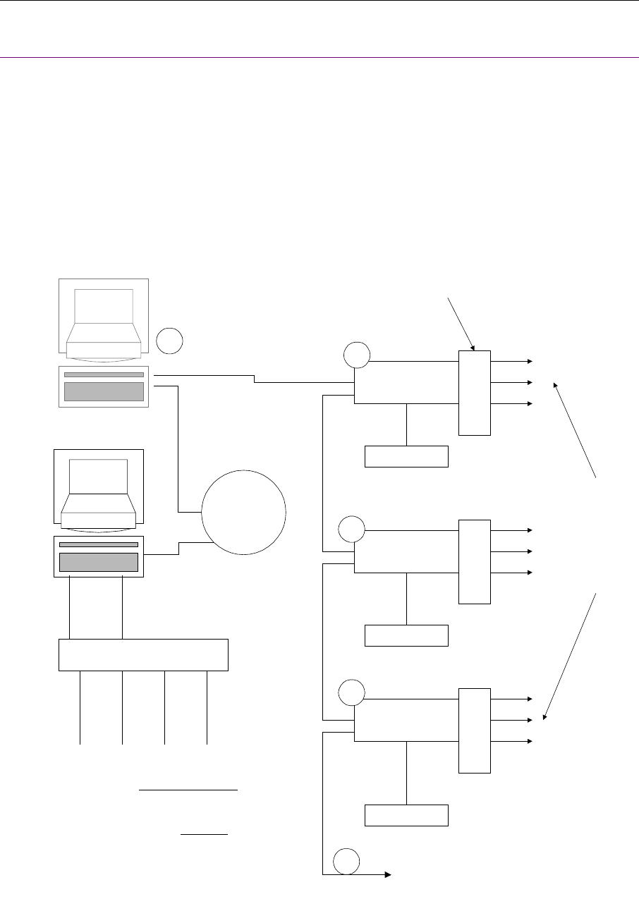
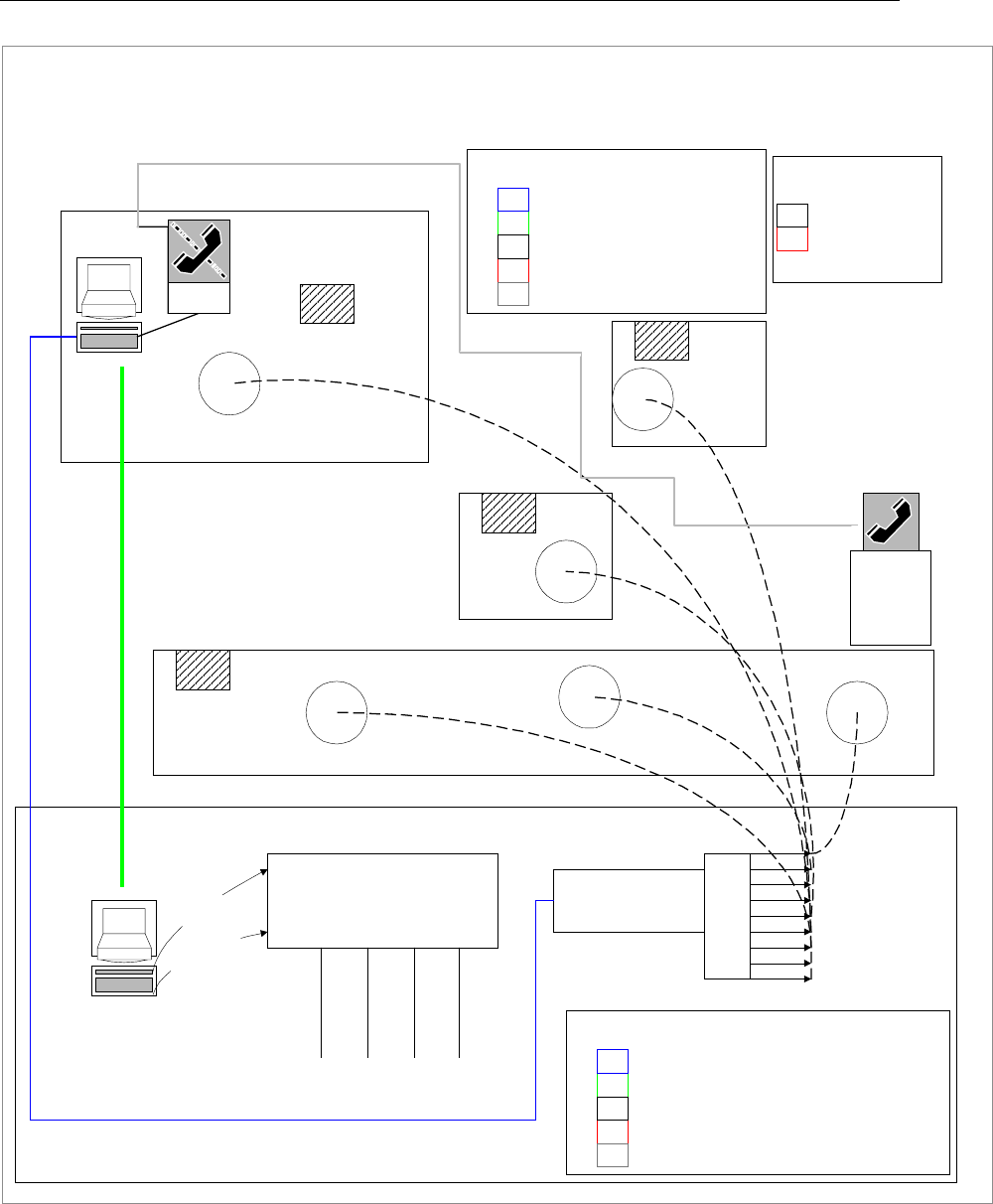
Figure 3-1. General Guidelines for Installations
Collector
Collector
Collector
Up to 6 total collectors. Last collector in the
AC Power
AC Power
AC Power
Punchblocks
Wire Types -
A - Ethernet
B - Collector Cable
C - Sensor Cable
D - Intercom Cable
B
B
B
B
C
C
C
C
C
C
C
C
C
Host Computer System
Maximum Wire Lengths
Total Length from V to Z
must be <= 4000 feet.
VW
X
Y
Z
EtherNet
Network
AA
A
Audio Switching Matrix
Intercom Modules
Optional Paging Computer System
RS-232 Audio Cable
DDDD
To sensors -
Up to 24 total
on each
collector.
chain has the TERMINATED/
UNTERMINATED switch set to the
TERMINATED position. All others have
switch set to UNTERMINATED.
See Section 8.3
Concentrator
Versus Technology, Inc.
DT10000-A0001 8 Revision 8 December 1998
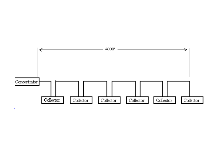
3.2 Collector Network Length Limitations
There must be no more than six (6) collectors on any one concentrator as shown in the RS-485 loop display
below. The total length of the collector network must not be more than 4000 feet. See Figure 3-2 for a visual
representation.
Figure 3-2
3.3 Sensor Connection Length Limitations
The single pair sensor connections may be up to 1000 feet in length. If the environment is known to be
electrically "noisy,” consider shorter line lengths to assure stronger signals and more immunity to interference.
3.4 Location of Collectors, and Concentrators
When planning an installation, it is important to locate a proper place for the concentrators and collectors. In
smaller installations, these items may all be located at the same place in a telephone or utility closet. Be sure
that the location selected has easy access for servicing, but that it can be secured against tampering by
unauthorized personnel.
The concentrator should be mounted in a central location to the collector(s) to minimize the lengths of collector
network runs. Many installations will find the concentrator simply mounted adjacent to the first collector.
Collectors should be mounted in similar telephone or service areas such that they are near the sensory networks
they service. Of course, be sure that the locations selected are free from extremes of heat, cold, and moisture as
with any electronic equipment.
NOTE:
The total length of an Ethernet network must be no more than 3000 feet. Consult the
Ethernet manual for more information on installation procedures.
Versus Technology, Inc.
DT10000-A0001 9 Revision 8 December 1998
NOTE: *** Collectors may be affected by high watt radio or paging antennas.***
DO NOT PLACE A COLLECTOR IN CLOSE PROXIMITY TO ONE OF
THESE ANTENNAS
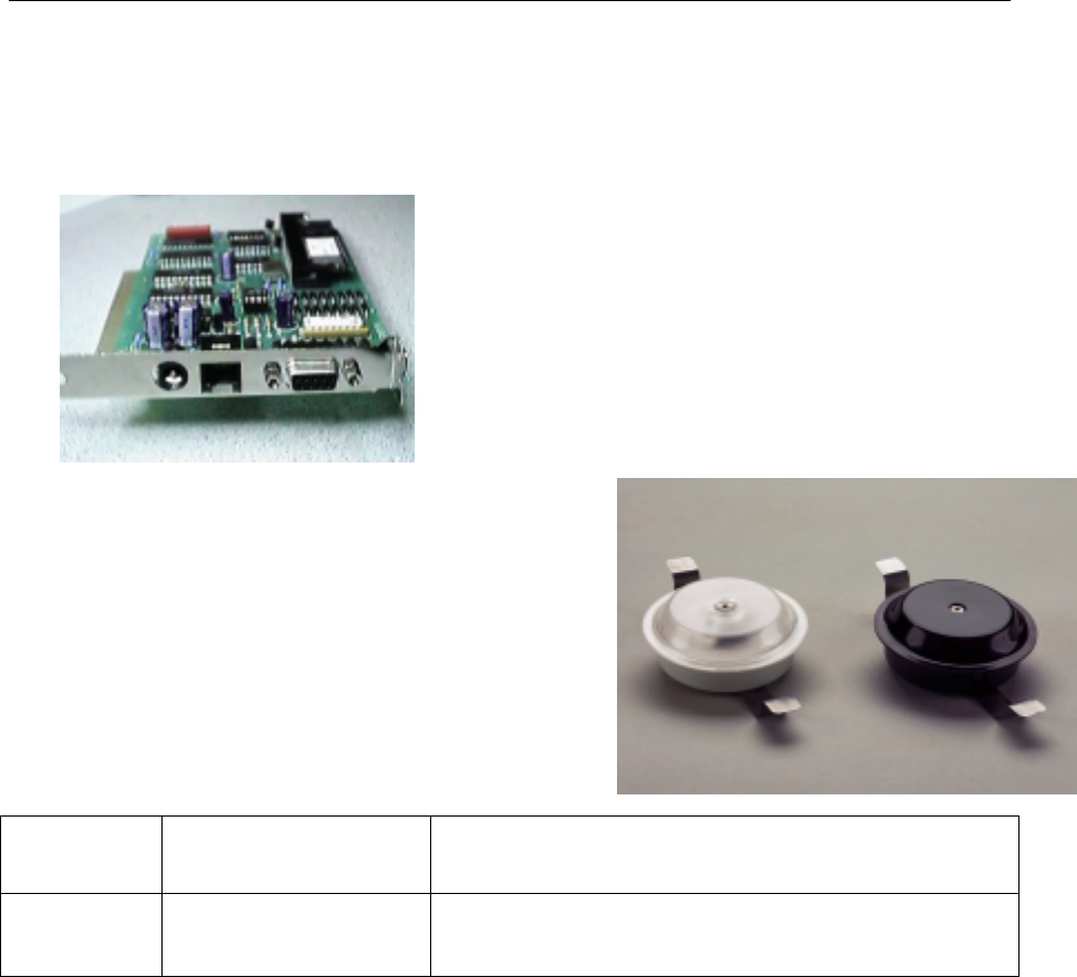
Internal Concentrator VER-2020
Note: If you are not using an Ethernet or Arcnet external
concentrator and your site is less that 150 sensors then you
may choose to use an Internal Concentrator (a plug-in PC
card) instead.
3.5 Sensor Location Planning
Perhaps the most important step in an installation involves
planning the sensor locations. A complete understanding
of sensors and tags is necessary to design an effective system.
Experience will prove to be invaluable in effective system design.
(Sensor S/N VER-4422 also available with white cover.) See
Section 7 for the sensor to punch-down wiring table. This is a
helpful example of proper sensor wiring planning and location
techniques.
IR Sensor VER-4422 white
VER-4420 black
RF Sensor VER-4450 –white only This device complies with part 15 of the FCC Rules. Operation is subject to
the following two conditions: 1) This device may not cause harmful
interference, and 2) this device must accept any interference received,
including interference that may cause undesired operation
3.6 Understanding High Frequency Sensor "Field-of-View"
The basic sensor "sees" the environment under it in a largely predictable pattern. However, there are other
factors that can affect the way a sensor sees. The sensor is like an eye, which is sensitive only to a narrow
spectrum of light, and the ID tag appears as a bright splash in an otherwise dark world to the sensor. Even if the
tag is blocked from the view of a sensor, it can often be detected. Though the infrared light from a tag does not
penetrate solid objects or bend around corners, it does reflect from surfaces in the room. This can sometimes be
mistaken for "seeing around corners." The effect of reflection can be used to advantage by the clever system
designer, but can also pose problems for the unwary installers. The area that a sensor can see in a given
situation is referred to as the sensors "field of view." Sensors are specified to have a given field of view when
obstacles are not present, so actual installed field of view may differ.
If a sensor is placed in a room with obstacles and reflections eliminated, the field of view of the sensor appears
in the shape of six overlapping lobes forming a 16-foot radius. Lower ceilings reduce the effective sensor
pattern diameter considerably due to angles involved.

Versus Technology, Inc.
DT10000-A0001 10 Revision 8 December 1998
3.7 Effective Coverage of Rooms
When planning the location of a sensor in a room, one should take into account the human factors involved.
The majority of activity in most offices occurs towards the center of the room, and people do not often stand in
corners, or near walls. A single sensor placed near the middle of the ceiling area can usually effectively cover a
normal office or meeting room. If the office is oddly shaped or very large, two sensors may be required.
Offices or rooms as large as 30 feet square are generally well served by a single sensor.

Versus Technology, Inc.
DT10000-A0001 11 Revision 8 December 1998
3.8 Special Problems with Sensor Coverage
The placement of sensors is usually a simple matter, but there are some special things to remember when
planning a system installation. The system planner should consider that a sensor may have a field of view
which extends out of the designated area through a doorway or passage, and that tagged persons might be
detected incorrectly and reported to be in the room when only passing by. Consider placing sensors away from
doors or entryways to prevent this. Sensors can be positioned so as to limit their view by placing them in
locations where existing obstacles serve to block the unwanted sensor view.
Due to the line-of-sight nature of the infrared light created by the ID tags, it is also possible to apply masking to
the sensor to limit or control the field of view. This masking of the sensor has been done with great success, but
may require some experimentation to refine for each application. However, proper placement is always the
preferred method for controlling, rather than eliminating, sensor field of view.
If the room has windows that allow a large amount of sunlight to enter the room, the sensor is best placed in a
position such that the sunlight is not reflected directly into it by the floor or furniture. Extremes of daylight can
decrease sensor range and field of view if allowed to enter the sensor. Window tint films that block infrared
(heat) energy greatly reduce this effect.
Of course, the sensor should be located such that it is afforded the best possible view of the room and the
persons in it. If the room is of complex shape and no single sensor position will provide adequate coverage,
multiple sensors should be considered.
3.9 Overlapping Sensors
Sensor overlap occurs when two (or more) sensors are placed such that their fields of view are coincident
(overlap) in some area. Allowing the field of view of one sensor to overlap that of another will, as one would
expect, cause some indecision in the system if both sensors observe an ID tag at the same time. The software
will not change the location of a tag when it is in an overlap area unless the software is told to ignore overlaps.
If overlaps are ignored a tag may appear to bounce back and forth as long as it is in an overlap condition.
3.10 High Frequency Light Interference
NOTE: Certain types of energy efficient lighting and associated electronic ballast’s may interfere
with the operation of a sensor that is within in the range of the light fixture.
In addition, the light emitted by fluorescent fixtures adds a high degree of noise to the sensor environment. The
sensor should be mounted such that light from florescent fixtures is not in direct sensor view. Excessive noisy
fluorescent energy can cause intermittent sensor reception and reduced range. "Warm White" and other tubes
designed to emit more red color energy are more of a problem than conventional "cool white" tubes.
• The use of High Frequency sensors will avoid most light interference problems.
The most common offenders are classified as T8 lights and have electronic ballast in the 40 kHz
range.

Versus Technology, Inc.
DT10000-A0001 12 Revision 8 December 1998
3.11 Use of Unauthorized Components
Your system is an innovative, high technology system that integrates hardware and software to create a safe,
reliable and efficient system. Use of components or connection to equipment not approved by the manufacturer
is NOT recommended and will invalidate any and all warranties.
Approved third-party components include wire and connectors, terminal blocks, and other interconnection
means only. Questions regarding the use of third-party equipment or components should be directed to your
dealer for clarification before being connected to your system.

Versus Technology, Inc.
DT10000-A0001 12 Revision 8 December 1998
4. INSTALLATION GUIDELINES
4.1 General
When installing a system, certain rules and limitations must be observed. The system is designed for trouble-
free operation in all environments, and adherence to these guidelines is critical for a reliable installation. The
following sections will detail the things that must be included in a system to ensure a successful installation.
4.2 List of Materials
Installation activities require a minimum amount of materials, some of which may be purchased by the installer
independent of Versus. For materials supplied by Versus, refer to the packing list and confirm that all listed
hardware and wire can be identified. For installer-purchased material, insure that the remaining materials are
available for the installation shown by the floor plan schematic diagram.

Versus Technology, Inc.
DT10000-A0001 13 Revision 8 December 1998
4.3 List of Tools
Some installation activities require special tools. Refer to Table 4-3 for a list of recommended tools.
Table 4-3. List of Tools
Tool
Cable stripper
Cordless Drill
Diagonal Clippers
Digital Multi-Meter
Electric Screw Driver
Ethernet Supplies
Fishtape
Hole Saw 2 3/8” Drill Attachment
Level
Mounting Screws
Nut Drivers
Paper/Pens
Punch-down Block Tool-Type 66
RJ-45 Testers
RJ Connector Terminator Tool Kit
Scissors
Screwdriver Assortment
Splice Crimp Tool
Small Hammer
Electrical Tape
Tape Measure
Twist Ties
Utility Knife
UY Connectors
Vise grip Pliers
Walkie Talkies
Weidmeuller Patch Check Plus
Wire Strippers

Versus Technology, Inc.
DT10000-A0001 14 Revision 8 December 1998
4.4 Safety and Code Considerations
Safety procedures and adherence to local building codes are the responsibility of the system installer. Versus
products have been designed to be safe and reliable under the conditions in which they are intended to be used.
The following sections detail those aspects of the system that might affect safety.
4.5 Equipment Handling
The components used in a typical installation contain internal circuits that are sensitive to static electricity.
Static electricity transported by the human body may be strong enough to damage internal circuitry during
installation. These components do not normally have exposed connector pins, but if handling with exposed
connectors or pins is required, the installer should use an anti-static wristband connected to an electrical ground.
This is especially important when temporarily disconnecting and reconnecting cables. The badges are the only
system components that people can come in direct contact with. Therefore, cleaning the badges after each use
is recommended. A badge should be thoroughly cleaned after each use, and wiped down with a disinfectant.
The disinfectant should be alcohol-based, not water based.
4.6 Power Requirements
The components obtain low-voltage operating power from a local wall mounted “plug-in” transformer.
Transformers provided with the systems are Underwriter Laboratory (UL) approved. No components use 120-
volt AC line power directly, except the computer systems.
Notice: The hardware may be damaged if connections are made with the system power applied. Do not
attempt to connect or disconnect sensors, collectors, concentrators, intercom modules or any other system
components with power applied! Although damage will not occur in most cases, this practice is not
recommended and may void equipment warranties.
As with any electrical equipment, safety is a prime concern. The system poses no safety hazard, since it uses
only low-voltage DC power. However, installers must take adequate precautions to ensure that the low-voltage
wire runs do not come in contact with high-voltage electrical wires.
No powering device other than the plug-in units provided should be connected to the system without prior
authorization from the manufacturer.
WARNING
Make every effort to avoid touching bare contacts or connector pins when
handling system components in order to prevent the accidental transfer of static
to internal devices. Leave protective covers attached during installation.
WARNING
Use of powering schemes not approved by the manufacturer will void
equipment warranty.

Versus Technology, Inc.
DT10000-A0001 15 Revision 8 December 1998
4.7 Grounding of Equipment
All points in a system installation are connected to a common “ground” via their interconnect wires. No attempt
should be made to provide any additional earth ground or neutral connections to any sensor or collector.
Adding ground connections to multiple points in a networked system may introduce electrical system noises
that will interfere with normal system operation. Consult the manufacturer if special grounding requirements
must be met.
As with any electrical equipment, safety is a prime concern. The system poses no safety hazard, since it uses
only low-voltage DC power. However, installers must take adequate precautions to ensure that the low-voltage
wire runs through ceilings and walls do not come in contact with dangerous electrical potentials and carry them
to points where they might be exposed to human contact.
No powering device other than the plug-in units provided should be connected to the system without prior
authorization from the manufacturer.
4.8 Codes and Ratings of Materials Used
The materials used in the construction of individual components meet or exceed UL fire retarding requirements.
However, not all these devices are rated for air plenum use. They are intended for utility closet mounting and
must not be placed in airways or plenum areas, unless they can be housed in approved enclosures and sealed to
meet local codes.
Installers must be aware of local fire and health codes in their selection of interconnect wiring. Plenum-rated
wire and cable must be used where it will pass through breathable air spaces. Wire and cable rated for plenum
use will be clearly marked. For information regarding plenum cabling, call Versus Technology, Inc.
Manufacturing Department.
4.9 Workmanship
The following standards of workmanship shall be followed during installation:
• National and local building codes shall be followed.
• Tools used shall be as recommended by the manufacturer, or approved equivalents.
• Connections shall be made with manufacturer’s recommended tools and procedures.
• Conductors shall not be nicked nor wire strands cut during wire stripping.
• Wire bundles shall be neatly dressed.
• Wire bundles shall be spaced away from power cables and lighting.
CAUTION:
Allowing sensor or network conductors to come into contact with metal surfaces and
structures, or allowing wires to be routed in close proximity of high powered equipment or
devices will introduce electrical interference and may cause erratic operation and/or
equipment failure.

Versus Technology, Inc.
DT10000-A0001 16 Revision 8 December 1998
4.10 Cable Types
Refer to Table 4-10 for a summary of the cable types recommended for installation. Approved equivalent types
may be used. Approved equivalent cable types may be used. Color coding tables have been included in order
to provide a systematic approach to all cabling in all installations.
Table 4-10. Recommended Cable Types
Sensor Cable CAT 5
Collector Cable CAT 5
Ethernet Cable CAT 5
Intercom Cable 7 cond. with drain, 26 AWG
shielded cable
4.11 Installation Checklist
The installation checklist (Section 14, page 36) is intended to be a record of the installation steps. Before
starting the installation, fill in the checklist by referring to the contractual floor plan schematic for the quantities
and numbers of zones and other components for the specific installation. Instructions for filling in the checklist
will be provided in the installation steps.

Versus Technology, Inc.
DT10000-A0001 17 Revision 8 December 1998
5. CABLE INSTALLATION
This section contains tips to aid in the installation of cables. When installing sensor and network wiring, normal
telephone installation techniques should be employed. Sensor wire runs should allow sufficient length to
move ceiling tiles and perhaps to move sensors if needed. The paragraphs are in order of component type
(for ease of identification and discussion of related topics) and are followed by the procedural steps.
5.1 Cable Installation
It is the responsibility of the installer to run all cables as indicated on the provided floor plan schematic
diagram. Each cable must be labeled at both ends with the identification of the end device to which it is run
(e.g., sensor, collector, or intercom unit). Collector cables should be labeled with the identification of the
collector that it runs to down the collector chain, away from the concentrator.
CAUTION:
Note that specific pin-color relationships have been defined in this section. Cables using RJ-
series plugs may appear to be usable, when in fact, they may not be correctly wired. Use only
cables pre-wired by the manufacturer or wired as described in this section.

Versus Technology, Inc.
DT10000-A0001 18 Revision 8 December 1998
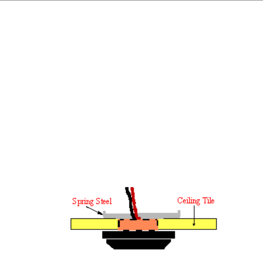
6. INSTALLING AND CHECKING SENSORS
Sensors are installed in ceiling tiles or ceiling surfaces using a 2-3/8" hole saw. The sensor is placed into the
hole and secured using the spring steel clip and the sensor cover to “sandwich” the ceiling tile. The spring steel
clip securely holds the sensor against the ceiling tile allowing for easy access for installing or replacing sensors.
6.1 Sensor Wiring
Normally, the UTP is run from the punch down to a sensor mounted in ceiling tile. Only a single pair of wire is
required for each sensor. No grounding at the sensor is required.
Normal infrared (IR) sensor installation calls for use of a splice connector at the sensor end of the cable run.
Sensor wires have no polarity and may be connected to sensor wire-pairs in either order. In the case of 2-pair
UTP cable, the same pair must be used at each end of the sensor run. It is suggested that the blue pair always be
used for consistency.
6.2 Sensor Wiring Steps
Perform the following steps to wire and install sensors:
1. Refer to the contractual floor plan schematic diagram and identify sensor locations and identification
numbers.
2. Insure that the collector has been previously installed.
3. Remove all bridge clips from the punch-down block.
4. Perform the following for each sensor:
a) Connect the sensor cable wire-pair to each sensor using UY splice connectors.
b) Gently bend the spring steel clips upward and insert the sensor into the ceiling tile hole.
NOTE:
Do not make any connections to components unless indicated by a step in the procedure.
CAUTION:
The sensor casing material is soft and is easily marred and scratched. Handle the sensors
with care.
CAUTION:
Always disconnect power from the system prior to connecting or disconnecting components.
Failure to do so may damage the equipment.
Versus Technology, Inc.
DT10000-A0001 19 Revision 8 December 1998
c) Connect the sensor wire-pair on the collector end to the associated punch-down block pin-pair using the
punch-down block tool.
d) Mark the sensor as installed on the Installation Checklist.
5. Checking Isolation:
In the course of interconnecting many sensors to a Collector, it is not uncommon to make contact with a sharp
metal edge, ganged knockout box, or electrical ground with one of the conductors. It is critical, however, that
such accidental connections be located and cleared prior to system start up. The effect of these accidental
connections can range from mild to severe. In many cases, erratic behavior may be noted. In some cases,
equipment damage may occur. In any case, an electrical code violation has been produced.
To verify that the system is "isolated" from building and electrical grounds, use an ohmmeter or multimeter set
to the 2K (2000)-ohm scale. Clip one probe to the nearest electrical conduit, electrical ground, or metal water
pipe and then touch the other probe to each punch block row in turn. Every row MUST indicate an infinite
(open) connection. If this is not the case, the suspect line must be traced to find the accidental connection to the
structure that has been made.
NOTE:
It may be helpful to disconnect the Collector from the punch block while this measurement is being
made. This will isolate the sensor wiring completely.
6. Repeat steps 4 and 5 for each collector.
7. Replace the bridge clips.

Versus Technology, Inc.
DT10000-A0001 20 Revision 8 December 1998
7. PUNCH-DOWN BLOCK INSTALLATION AND ORGANIZATION
The collector punch-down block is organized so that each two punch-down block rows, starting at the top, left
of the block are one sensor port. The last two rows are not used. Refer to the Punch-down Block Diagram
(page 21).
Bridge-clips are normally used to connect left-side pins to the right-side pins, which are wired to the collector
unit. If patching of sensor inputs is required, jumpers can be used from any sensor wire-pair on the left to any
collector wire-pair on the right.
The punch-down block is to be mounted on the wall at the designated site using appropriate wall-mount
hardware. The collector unit is mounted to the selected wall site, adjacent and connected to the associated
punch-down block, using the Velcro tape provided with the unit or other appropriate mounting bracket. When
using Velcro tape to secure a collector unit, it is important that the solid metal end clip is firmly secured to
prevent sagging of the collector to punch down block connection.
Install the punch-down block/collector unit(s) so as to allow for wiring access, neat wire routing and dress, and
connection of any sensor wire-pair to any collector input. Neat and orderly punch-down blocks are easier to
troubleshoot and maintain.
Versus Technology, Inc.
DT10000-A0001 21 Revision 8 December 1998
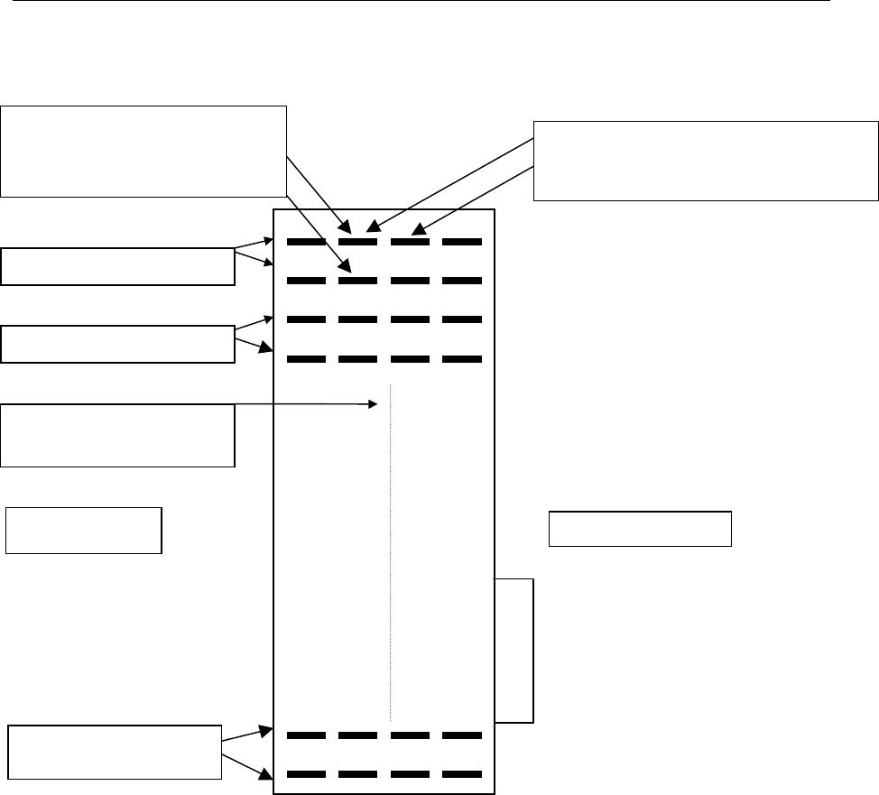
Figure 7-1. Punch-down Block Diagram
Sensor No. 1 pin-pair, 2 rows
Sensor No. 2 pin-pair, 2 rows
25t
h
double row of pins is
not used.
Sensor Wire
Side
Sensor connections continue
through 24 maximum.
Sensor wiring should be tested at these
pins before bridge clips are installed.
Check for isolation at this point.
Collector side
After sensor wiring has been verified, bridge
clips are installed across these pins for each
active pin-pair.
Collector Connection
Versus Technology, Inc.
DT10000-A0001 22 Revision 8 December 1998
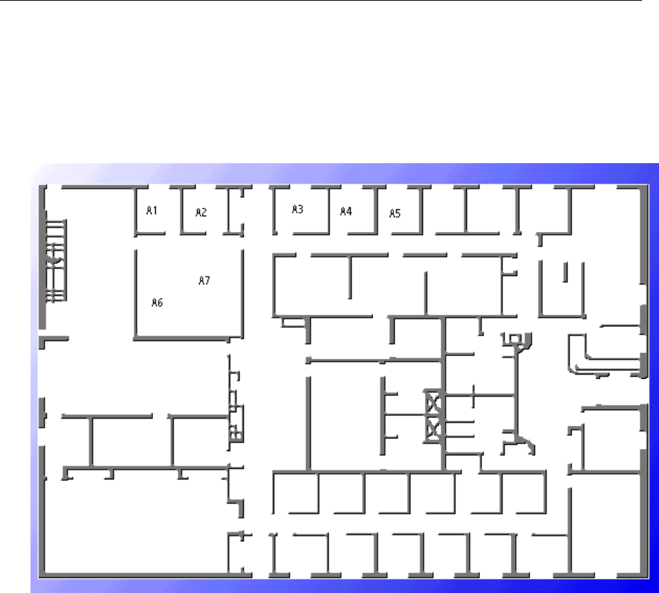
This floor plan and collector table is an example of a punch-down block wiring organization chart. It describes
the sensor numbers and the room assignments where each sensor and zone is located on the punch-down block
wiring.
Figure 7-2. Sensor Wiring Floor Plan
See the sensor and punch-down block wiring table on the next page for correct wiring locations and
connections.

Versus Technology, Inc.
DT10000-A0001 23 Revision 8 December 1998
Collector #
Punch-down
Block Pair Cable ID Zone Description
1A1
Gary’s Office
2 A2 Henry’s Office
3 A3 Bob’s Office
4A4Jon’s Office
5 A5 Sharon’s Office
6 A6 Conference Room
7 A7 Conference Room
8A8
9A9
10 A10
11 A11
12 A12
13 A13
14 A14
15 A15
16 A16
17 A17
18 A18
19 A19
20 A20
21 A21
22 A22
23 A23
24 A24
1. The punch-down block pair represents a pair of sensor wires.
2. The Cable ID represents the identification of the cable run from a location within
the facility back to the punch-down.
3. The room name or location name is then put into the Zone Description category.

Versus Technology, Inc.
DT10000-A0001 24 Revision 8 December 1998
8. INSTALLING AND CHECKING COLLECTORS
Locate the punch block and collector unit(s) carefully to allow for wiring access, neat wire routing and dress,
and expansion space for future collectors that may be added as the system is expanded.
8.1 Checking the Collector Wiring
A quick visual check of the collector wiring should find that the punch block is secure and that the collector unit
connector is firmly seated against the punch block connector. See section 13.1 the Collector Voltage
Troubleshooting Flow Chart for checking the collector wiring.
The collector network (2-pair) must be tested before the system power is applied to be sure that wires are not
misconnected. Failure to thoroughly test the collector network wiring may result in equipment damage.
The concentrator and collector devices connect to the 2-pair wiring system using modular interfaces to allow for
easy testing of the wiring before power is applied. It is recommended that install crews be equipped with
appropriate USOC cable testers as required to verify the polarity and validity of installed wiring.
Note that 3-pair USOC interconnections may also be used. In this case, the third pair (outermost) will be used
in parallel with the second pair to improve power distribution to the collectors.
8.2 Checking Isolation
In the course of interconnecting many sensors to a collector, it is not uncommon to make contact with a sharp
metal edge, ganged knockout box, or electrical ground with one of the conductors. It is critical, however, that
such accidental connections be located and cleared prior to system start up. The effect of these accidental
connections can range from mild too severe. In many cases, erratic behavior may be noted. In some cases,
equipment damage may occur. In any case, an electrical code violation has been produced.
To verify that the system is "isolated" from building and electrical grounds, use an ohmmeter or multimeter set
to the 2K (2000)-ohm scale. Clip one probe to the nearest electrical conduit, electrical ground, or metal water
pipe and then touch the other probe to each punch block row in turn. Every row MUST indicate an infinite
(open) connection. If this is not the case, the suspect line must be traced to find the accidental connection to the
structure that has been made.
NOTE:
It may be helpful to disconnect the collector from the punch block while this measurement is
being made. This will isolate the sensor wiring completely.
CAUTION:
Correct two-pair wiring is essential. Crossed or reversed pairs can cause equipment damage
in some cases. ALWAYS TEST ALL WIRING PRIOR TO CONNECTION OF SYSTEM
POWER SOURCES.
Versus Technology, Inc.
DT10000-A0001 25 Revision 8 December 1998
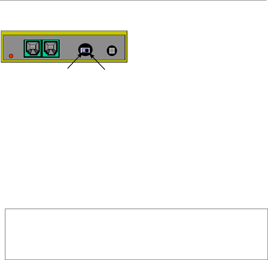
8.3 Setting the "Last Unit" Switch
When installing collectors, the collection
network wires are run from unit to unit in a daisy chain
fashion. Each collector has a small switch on it that is
used to identify it as the last collector on a line. It is
very important that the collectors which are NOT at
the end of the line have this switch set to the
UNTERMINATED position, and that the collector
which is at the end of the line has this switch set to the
TERMINATED position.
NOTE:
The last collector in a segment must have the terminate switch set to the Terminate position.
Why? With high speed digital data, it is critical that the electrical energy that runs down the wires is absorbed
at the end and does not "bounce back" down the wire and cause interference with other data coming down. To
exactly absorb all the energy coming down a wire, the wire must be ended at the last device in the chain with a
resistor, which has value that equals the characteristic impedance of the wire. Each collector unit is equipped
with such a resistor that is connected when the switch is in the TERMINATED position.
8.4 Power-up Test
When the collector wiring and isolation have been verified and the cable connection between the concentrator
and the collector has been tested and found correct, the next step is to apply power to the collector and check the
sensor connections for the correct voltages.
8.5 Sensor Voltage Test
Once power has been applied to the collector, a voltmeter check should be made of the sensors on the punch
block to verify that they are connected correctly. This is done using the voltmeter or multimeter set to a 20-volt
range. Apply the probes to each sensor connection on the punch block and verify that the voltage reading is
approximately 16 volts. If the reading is approximately 20 volts, then there is no sensor connected to this pair or
the wiring to the sensor is open. If the connection is approximately 16 volts, then the sensor is wired correctly
to a single sensor. If the reading is very low or zero, the sensor pair is shorted. (Of course, the 25th pair on the
punch block is unused and will read zero volts.) RF interference may be verified by switching the meter to the
AC scale and reading the voltage. With no tag transmitting over the sensor there should be < 0.1 VAC on a
sensor pair. When all the sensor pairs that have sensors connected are reading correctly, proper sensor
connections are assured.
Terminated Unterminated
Collector
CAUTION:
If the red LED indicator was lit in the concentrator power-up test but does not light now,
remove power from the concentrator quickly and recheck the two-pair wiring. A short
circuit may have occurred in the connection of the collector. (If this occurs, a safety fuse
internal to the concentrator may be blown.)

Versus Technology, Inc.
DT10000-A0001 26 Revision 8 December 1998
8.6 Local Powered Collectors
Collectors are provided with a 24V-power supply that must always be used for each collector, providing local
operating power. No other power supply is adequate to power collectors.
8.7 Collector Network Wiring Connections
Concentrator End Connections
The 2-pair collector network connects to the concentrator unit using a modular connection with a RJ-12
modular jack (6 wire). This provides a means to easily disconnect the collector network for testing of the 2-pair
wires or for service of the collector unit.
Collector End Connections
The 2-pair collector network connects to the collector module via a modular connector with a RJ-12 modular
jack (6 wire). A modular-to-modular jumper is then used from one collector unit to the next collector unit. This
provides a means to easily disconnect the collector unit for testing of the 2-pair wires or for service of the
collector unit.
NOTE:
If the voltmeter is applied to a sensor pair, a slight drop in voltage can be observed when the
sensor is receiving a transmitting ID tag. This can be used to identify sensors in lieu of
complete system operation.
CAUTION:
A shorted sensor pair will not cause immediate damage to the collector. However, if allowed
to remain, some heating of collector components will occur which is undesirable. If shorted
pairs are noted in the sensor voltage test, remove the collector power and resolve the shorts as
soon as possible. If the system must be powered with the short unresolved, remove the
Punch-block bridging clips to disable the disruptive sensor until the wiring can be repaired.

Versus Technology, Inc.
DT10000-A0001 27 Revision 8 December 1998
9. COLLECTOR WIRING
The collector devices connect to the sensing network using modular interfaces to allow for testing of the wiring
before power is applied. It is recommended that installers are equipped with appropriate cable testers to verify
the polarity and validity of installed wiring.
There are two parallel RJ receptacles on each collector. This allows collectors to be chained together from their
assigned concentrator to the last collector in the chain. A key indication of connector problems with the
collector cable, either reverse polarity or a short circuit, is the red indicator light on the collectors. The red light
will flash every time it sees a badge fire. A constant pattern of 4 or 5 flashes may indicate there is a problem
with the connectors on the cable.
9.1 Collector Wiring Steps
1. Refer to the contractual floor plan schematic diagram and identify the concentrator location.
2. Refer to the contractual floor plan schematic diagram and identify all collector locations.
3. Verify that each collector cable for each collector site and the concentrator site has been installed as
indicated on the contractual floor plan schematic diagram.
4. Attach a RJ connector to each end of the collector cable as shown in Table 10-1.
5. Using the Weidmeuller Patch Check Plus test set or an equivalent model, perform the following steps to
verify straight through continuity for each collector cable run:
a) Plug one end of the cable into the receiver unit of the test set.
b) Set the reset switch on the receiver unit to the “On” position
c) Plug the other end of the cable into the Transmitter unit of the test set.
d) Set the reset switch on the transmitter unit to the “On” position. All the red LED’s will light followed by
an audible squawk tone.
e) Touch the TEST button on the transmitter. After a short delay, the transmit #1 LED will light with the
corresponding #1 LED on the receiver scale
f) Touch the TEST button again to light transmit #2 LED with its corresponding receiver #2 LED.
g) Repeat this process until all conductors in the cable have been verified for continuity.
NOTE:
Do not make any connections to components unless indicated by a step in the procedure. Insure
that all bridge clips have been removed from the selected Punch-down Block/collector unit.
Versus Technology, Inc.
DT10000-A0001 28 Revision 8 December 1998
6. Mark the collector cable as checked on the Installation Checklist.
7. For each collector perform the following:
a) For the collectors identified on the contractual floor plan schematic diagram as LAST, set the
UNTERMINATED/TERMINATED switch to the TERMINATED position. For all other collectors,
set the switch to UNTERMINATED.
b) Insert the RJ plug(s) into the collector receptacle(s) (either collector receptacle is acceptable.)
c) Mark the collector as installed on the Installation Checklist.
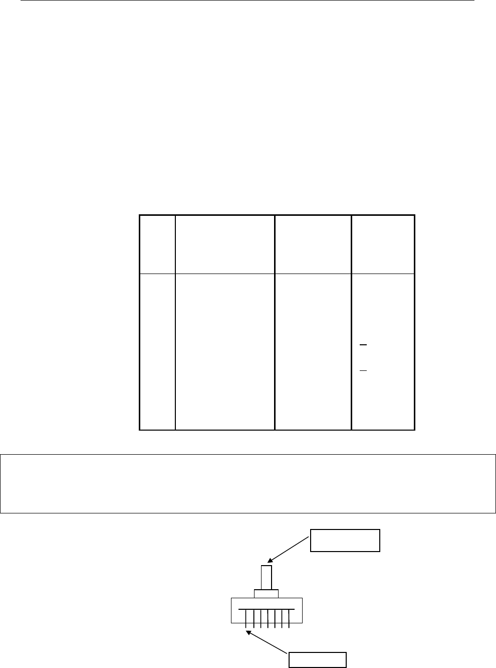
Table 9-1. Collector RJ-12 Plug Wire Colors
Plug
Pin
No.
CAT 5 Wire
Color Description Voltage
3 White/Blue Data (+) + 1 VDC
4 Blue Data (-) + 1 VDC
5 White/Orange Ground 0 VDC
6 Orange Ground 0 VDC
NOTE:
With connector pins pointing toward the installer, cable away from the installer, pin 1 is to the left.
See diagram below.
Pin 1
Top Tab

Versus Technology, Inc.
DT10000-A0001 29 Revision 8 December 1998
10. CONCENTRATOR INSTALLATION
The selection of external or internal concentrator’s depends on the installation.
10.1 Computer Network Card
The computer should be equipped with an appropriate network card for Arcnet and/or Ethernet Concentrator
installation
10.2 Internal Concentrator Installation
The Internal Concentrator is installed inside the computer in an appropriate expansion slot. Follow the standard
installation procedures for any computer hardware device. A network card is not required with this type of
installation.
10.3 External Concentrator
The External Concentrator is a “table-top” box assembly, which can be allowed to sit on a level surface. It may
also be mounted on any flat surface with mounting clips. Mount all external concentrators as indicated on the
floor plan schematic diagram.

Versus Technology, Inc.
DT10000-A0001 30 Revision 8 December 1998
11. INSTALLING AND CHECKING THE EXTERNAL CONCENTRATOR
The Concentrator Power Supply should be secured to the electrical outlet using a screw or other means to
ensure that it cannot fall out or is disconnected by others working in the same area.
Do NOT plug in the power supply cable until the installation wiring checks are completed. System
damage could occur.
11.1 Network Wiring for Arcnet and Ethernet Concentrators
Arcnet Concentrator
The Arcnet Concentrator requires coaxial cable runs between the network card in the computer and the Arcnet
Concentrator. For multiple concentrator’s, install an appropriate hub. An Arcnet Concentrator requires a 20V
power supply with a securely crimped BNC connector. This is recommended because tests have shown that
screw on BNC connectors are unreliable and inconsistent. It is also recommended that Arcnet hubs utilize a
UPS to protect it if the power is interrupted in a facility. This will allow the concentrator to run on a battery
operated UPS supply. Concentrators can fall out without them. Correct Arcnet cabling needs to be RG62 at
93OHM, for correct specifications.
Ethernet Concentrator
The Ethernet Concentrator requires CAT 5 four pair UTP cable runs between the network card in the computer
and the Ethernet Concentrator. For multiple concentrator’s, install an appropriate network hub or it may also be
connected to an existing Ethernet network within a facility. Ethernet Concentrators call for a 24V power supply
same as the collectors. For more information on the Ethernet Concentrator, refer to the Ethernet Concentrator
manual, Revision 4.
11.2 Power-up Test
When the wiring has been examined and the power supply voltage has been found to be in range, a power up of
the concentrator may be performed to verify its operation.
Plug the power supply connector into the concentrator and observed the red LED indicator lights. If it fails to
light, recheck the power and connections.
CAUTION:
Disconnect the modular cable from any down channel collector(s) and allow it to remain
unconnected during the test. Down channel collectors could be damaged if power is
applied before they have been checked.
Note:
The Wire Run Check-off diagram is included in this manual as a visual reference of cable
runs for system installation. See the Wire Run Check-off Sheet on the next page.
Versus Technology, Inc.
DT10000-A0001 31 Revision 8 December 1998
Nurse's Station
Host
Sensor
Speaker
Mic Unit
S/M
ASM Closet
Pager
Audio Switching Matrix
DDD
Collector
Sensor Wire
Ethernet Network Wire
Intercom Wire
Signal
Controller
S/M
Collector Wire
Collector Wire
Nurse's Station Wire
Collector Wire
Ethernet Wire
Sensor Wire
Intercom Wire
Phone Wire
All Rooms
Sensor Wire
Intercom Wire
ASM Closet
Collector Wire
Ethernet Wire
All Sensor Wires
All Intercom Wires
ASM Wires-Signal and Controller
Telephone
Analog line
to the
outside
Modem
Hall Way
Room
Room
S/M
Wiring Run Check-off for Internal
Concentrator System
S/M
Phone Wire
Versus Technology, Inc.
DT10000-A0001 32 Revision 8 December 1998
12. HARDWARE COMPONENTS
The table in this section provides a list of hardware, system, and sensor part numbers.
Table 12-1. Hardware Components
Part Number Product Name
Badges
VER-1400 Tracking Badge
VER-1450 Personnel Badge
VER-1550 Equipment Monitoring Badge
Sensors
VER-4420 (Black),
VER-4422 (White) H/F Sensor
Network and Audio Support
Components
VER-2015 External Concentrator (Ethernet)
VER-2020 Internal Concentrator Kit
VER-2402 Collector Kit (with punch down and power supply)
VER-4600 Audio Switch Matrix
VER-4620 Speaker/Mic Unit

Versus Technology, Inc.
DT10000-A0001 33 Revision 8 December 1998
13. TROUBLE SHOOTING GUIDE
These are possible hardware trouble scenarios and solution issues that may affect the operation of the tracking
system. The Collector Voltage Troubleshooting Flow Chart and the Functionality Test Flow Chart are included
as troubleshooting strategies for correcting system hardware problems.
Problem: System will not start up.
Discussion: Most system failures on startup are caused by failure to properly crimp RJ Type connectors, along
with failure to test the completed connection.
Problem: Collector cannot be seen by the Concentrator on the Subnet.
Discussion: A collector works properly when unconnected to the subnet, on powering on, it blinks four to five
times every five or so seconds. Once connected to the concentrator’s subnet, upon power on, the collector light
should come on strong after the first few seconds and then blink only upon receipt of a badge ID.
Problem: Incorrect voltages across sensor pair at the punch down block.
Discussion: The voltage across the sensor pair at the collector punch-down block should be between 15 and 17
volts DC. A voltage above18 may indicate an open circuit, while a voltage below 15 may indicate RF
interference, or faulty sensor, or faulty wiring. RF interference may be verified by switching the meter to the
AC scale and reading voltage. With no tag id’s being sent down the sensor pair, any AC voltage reading may
indicate RF interference.
Problem: RF interference.
Discussion: RF may be checked as discussed above. Possible RF interference that effect the sensor network
include, certain types of energy efficient lighting and associated electronic ballasts. The most common
offenders are classified as T8 lights and have and electronic ballast in the 40 kHz range. Sensor wiring should
not touch electrical conduit, or ceiling grates, as they are very good at picking up RF frequencies.
Problem: Sensor not picking up id from tag (non-working sensor).
Discussion: Smoke detectors using IR detection interfere with Versus sensors. The sensor should not be
installed within two feet of smoke detectors to avoid any interference.
Problem: Collector mounting failures.
Discussion: Collector mounting failures can be avoided by using the mounting clip provided to hold the end of
the collector firmly against the wall.

Versus Technology, Inc.
DT10000-A0001 34 Revision 8 December 1998
Trouble shooting guide
Condition Possible Cause Remedy
System fails to start up. Faulty wiring Re-crimp RJ type connectors.
Red light on collector flashes in
a constant pattern.
Two flashes Power trouble Check to be sure unit connections
are secure and adequate power
has been applied.
Three flashes Disconnect the collector from the
punch down block. If the
flashing pattern continues the
problem is in the collector. If it
stops, one or more sensor inputs
is reporting a constant R
input????
Four flashes 485 Data wiring reversed Reverse pair from collector to
concentrator.
Five Flashes No data error No subnet data observed check
the 485 line to the concentrator.
Voltage across sensor pair is <
15 Volts DC Faulty wiring
Faulty sensor
RF interference
Check for RF interference.
RF interference me verified by
switching the voltmeter to AC
scale and reading the voltage.
With no tag inputs the AC
reading should be
> .1 volt
Voltage across sensor pair is >
18 volts. Open circuit. Check wires for opens.
Versus Technology, Inc.
DT10000-A0001 35 Revision 8 December 1998
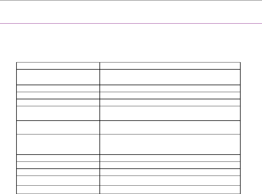
13.1 Collector Voltage Troubleshooting Flow Chart
Replace Sensor
Collector
Voltage
Level Low
or High?
Replace collector
Voltage Level <15 Volts Dc
NoYesNoNo
Voltage Level >17 Volts Dc
Check
Sesnor for
EMI
Sensor Wire
too close to
ceiling tile
railing
Sensor too
close to
High freq.
light
Replace Collector
No
Goto
Voltage Test
Move Wire
Move Sensor
Yes
Yes
Check for Open
Wires between
sensor &
punchdown
block
Check
Collector
Voltage
Levels
Replace Collector Done
Fix or Replace
Wire
Yes
No
Good Votage Levels
Bad Voltage Levels
Collector Voltage Troubleshooting
Flow Chart
Voltage
Test
Check
Sesnor for
wires
shorted
together
Fix wiring
Yes
Versus Technology, Inc.
DT10000-A0001 36 Revision 8 December 1998
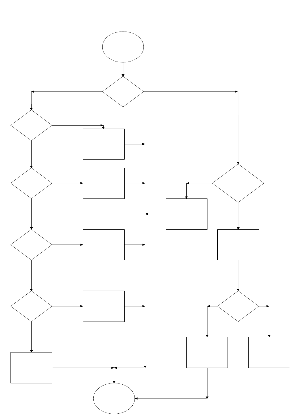
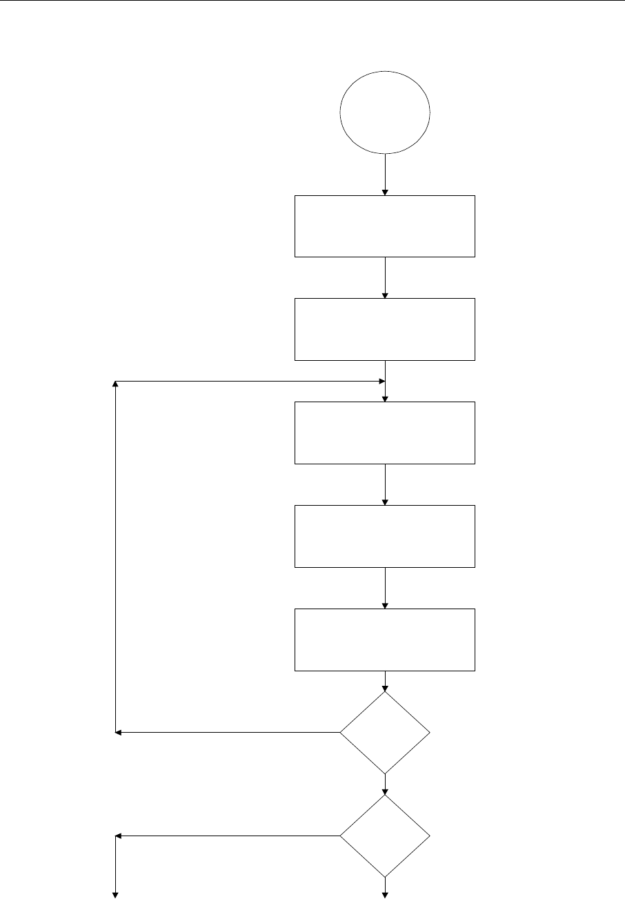
13.2 Functionality Test Flow Chart
Functionality
Test
Choose a sensor Location
Start Frequency Program
Start in the middle of the sensor, walk
out at 6" intervals with a badge four
feet off the floor.
Record these readings
Repeat reading around
sensor at 30 degree
intervals.
Next Sensor
Are there
any dead
spots
Goto Light Test Page
Check another Sensor
Done
Done
Functionality Test Flow Chart

Versus Technology, Inc.
DT10000-A0001 37 Revision 8 December 1998
14. INSTALLATION CHECKLIST
The table and inspection report in this section will be used to indicate the completed installation and test of
hardware and wiring. The installation codes will be as follows:
C = Cable checked I = Installed hardware
Make copies of the table and enter the numbers of the hardware as they are installed. Indicate a cable check
completion with a “C” and a hardware installation completion with the “I” in each numbered cell of the table.
The installer will be directed by the steps of the installation to make these entries as the checks and installation
are made.
Copies of the entries should be kept with other installation documentation.
Item Versus P/N Quantity Hardware
Installation System
Installation
Sensor Cable 2 pair UTP plenum 24 AWG, solid
Collector Cable 2 pair UTP plenum 24 AWG solid
Intercom Module Cable 7 Conductor 26 gauge,
stranded , shielded w/drain
UY connectors
UR connectors
Network Cable
Cable Labels
Cable ties
Sensors - High Frequency
Sensor Mounting Brackets Optional
Collector Kits
Concentrator
Intercom/ Speaker Units
Channel for wire between Speaker Units
RJ 12
RJ 45 (for shielded cable use shielded RJ 45
connectors)
Host Computer System
Pager Computer System
Audio Switch Matrix
Remote Monitor (Optional)
VGA Splitter (Optional)
Magnetic Doorlocks (Optional)
Doorlock Control Interface (Optional)
Personnel Badges
Equipment Badges
Equipment Badge Cables - Bear33
Equipment Badge Cables - PLV
Equipment Badge Cables - Monaghan

Versus Technology, Inc.
DT10000-A0001 38 Revision 8 December 1998
Equipment Badge Cables - Newport Breeze
Equipment Badge Cables - MDE Escort
P-Badge Labels
E-Badge ID Code Labels
Hardware Installation Manual & Drawings
Software Licenses
Software Backups
--Some Optional--
Sensor Splice Crimp Tool
Punch-Down Tool - Type 66
RJ Connector Terminator Tool Kit
Ethernet Connector Terminator Tool Kit
Ethernet Supplies
Electric Screwdriver
Cable Stripper
Screwdriver Assortment - Incl’ Small
Nutdriver Assortment - Incl’ ASM Sizes
Diagonal Clippers - Small & Large
Digital Multi-Meter
Utility Knife
Flashlight
Visegrip Pliers
Small Hammer
Cordless Drill
2 3/8” Hole Saw
Fishtape
Center Punch
Step-Drill
Knock-Out Punch

Versus Technology, Inc.
DT10000-A0001 38 Revision 8 December 1998
14.1 Preventative Maintenance Inspection Report
Preventive Maintenance Inspection Report
Customer______________________________ Customer Number______________________ Date___________
FE ___________________________________ FE ID________ Call Number______________________________
Equipment Serial Number_________________ Software Revision _________
Configuration ( )
___ Host Computer Setup ___ Collector Setup ___ Software Intellimotion 3-Pack
___ Pager Computer Setup (Optional) ___ Punchdown Block Configuration ___ Software Pager (Optional)
___ Work Station Computer (Optional) ___ Concentrator Setup (Optional) ___ Software Misc. (Optional)
___ Network Wiring ___ Sensors
___ Sensor Wiring ___ ASM (Optional)
___ ASM Audio Wiring (Optional) Tools
1. Standard hand tools 3. RJ Tester 4, 6 & 8 Pins 5. ESD Mat and Wrist Strap
2. Multimeter 4. Hardware & Software Manuals
Visual Inspection ( )
Inspect the following for excess wear and/or any visual signs of damage.
1. ___ General 5. ___ Connectors 8. ___ Cable insulation
2. ___ Computers 6. ___ Sensor Mounting 9. ___ Collector Mounting
3. ___ Concentrator Mounting 7. ___ ASM Mounting
4. ___ Reseat socketed components/connectors
Cleaning ( )
1. ___ Clean all internals of dust 2. ___ Clean external surfaces 3. ___ Clean ASM Area
4. ___ Clean Sensor Work Area(s) 5. ___ Clean ASM Work Area(s) 6. ___ Clean All Computer Stations
7. ___ Clean Infrared Tag
Calibration ( )
1. ___ N/A Electrical Safety Checks ( )
1. ___ Wall Receptacle Test
2. ___ Sensor Voltage Test
3. ___ Collector RJ Line Continuity Test

Versus Technology, Inc.
DT10000-A0001 39 Revision 8 December 1998
Checkout Procedure ( )
System 1. ___ Connections Sensor/ASM 2. ___ Display 3. ___ Intercom Modules
Computers 4. ___ Software Setup 5. ___ Startup and Restart 6. ___ PC Anywhere & Modem
7. ___ Network
Concentrator 8. ___ Connection between Computers and Network (Optional)
Collectors 9. ___ Wiring Punch-down 10. ___ Mounting 11. ___ Random flashing Red LED
Sensor 12. ___ Sensor Test Software 13. ___ Voltage Check 14. ___ Software Move Test
ASM 15. ___ LED Power ON 16. ___ Intercom Connections 17. ___ ASM Test Software
Battery Install 18. ___ Battery Installation 19. ___ Tracking on System 20. ___ Activates Page (Optional)
Backups 21. ___ Backup Data from Computer Install
Training 22. ___ Completed