Mikrotikls SIA GROOVE-2HN 802.11 DIGITAL TRANSMISSION SYSTEM ROUTER User Manual
Mikrotikls SIA 802.11 DIGITAL TRANSMISSION SYSTEM ROUTER Users Manual
UserManual.wiki
>
Mikrotikls SIA
>
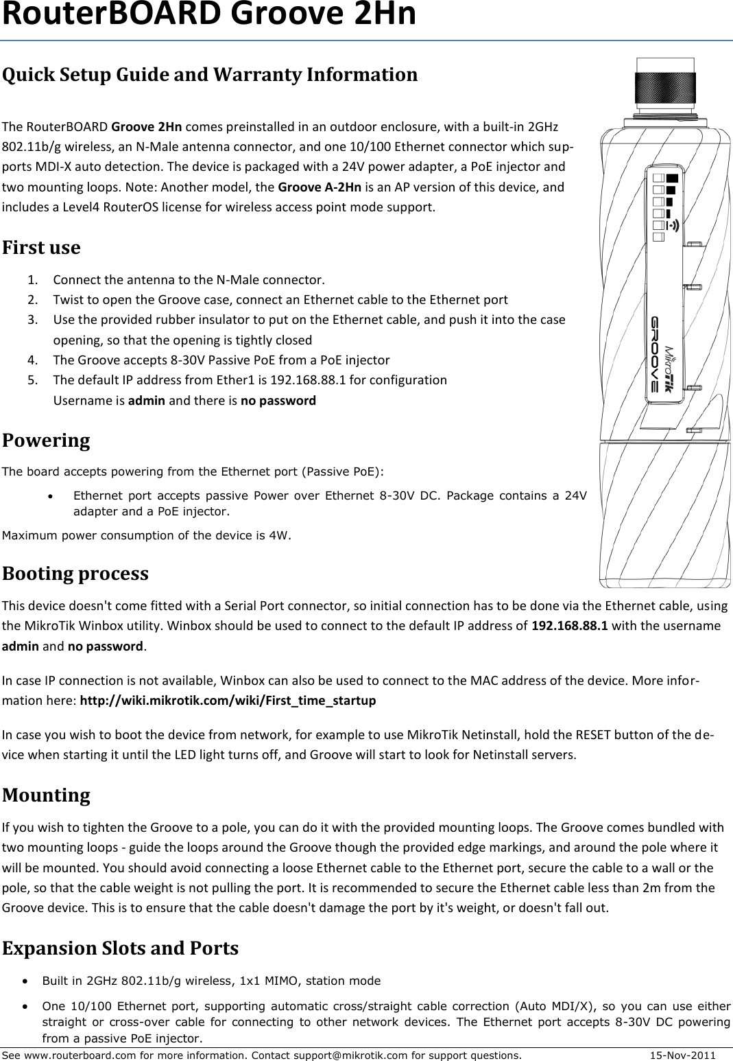
GROOVE 2HN User Manual
Users Manual
Navigation menu
Upload a User Manual
Namespaces
Wiki Guide
HTML
PDF
Info
Views
User Manual
Discussion / Help
Navigation