MilDef Crete DS11 Tablet Computer User Manual
MilDef Crete Inc. Tablet Computer Users Manual
UserManual.wiki
>
MilDef Crete
>
DS11 User Manual
Users Manual
Navigation menu
Upload a User Manual
Namespaces
Wiki Guide
HTML
PDF
Info
Views
User Manual
Discussion / Help
Navigation
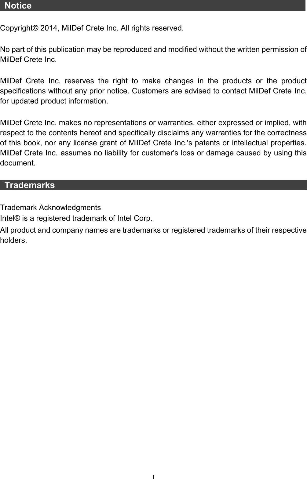

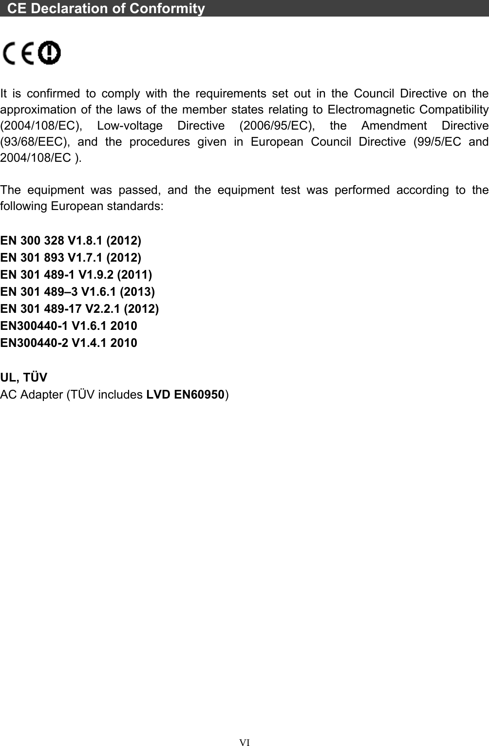

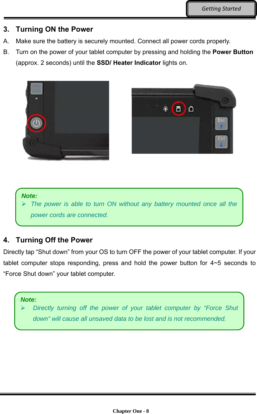
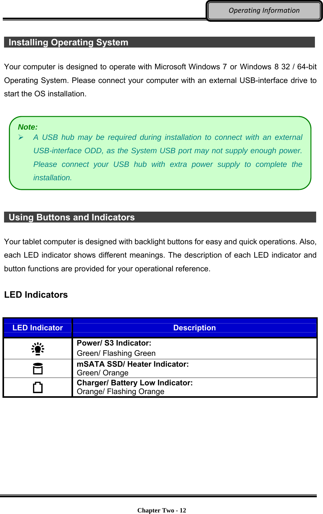
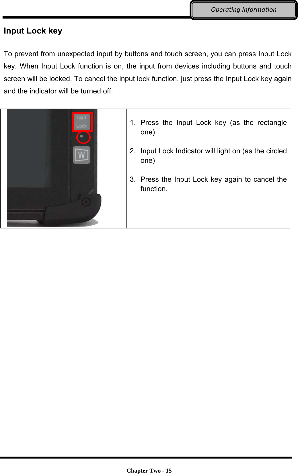
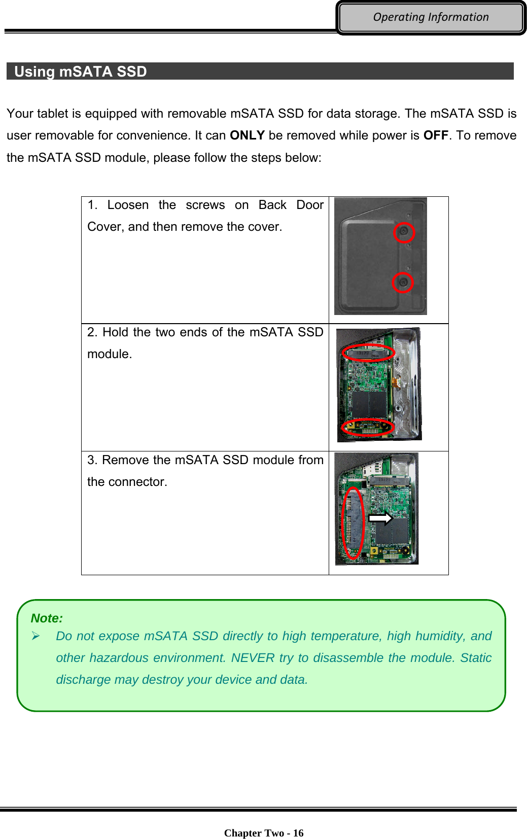
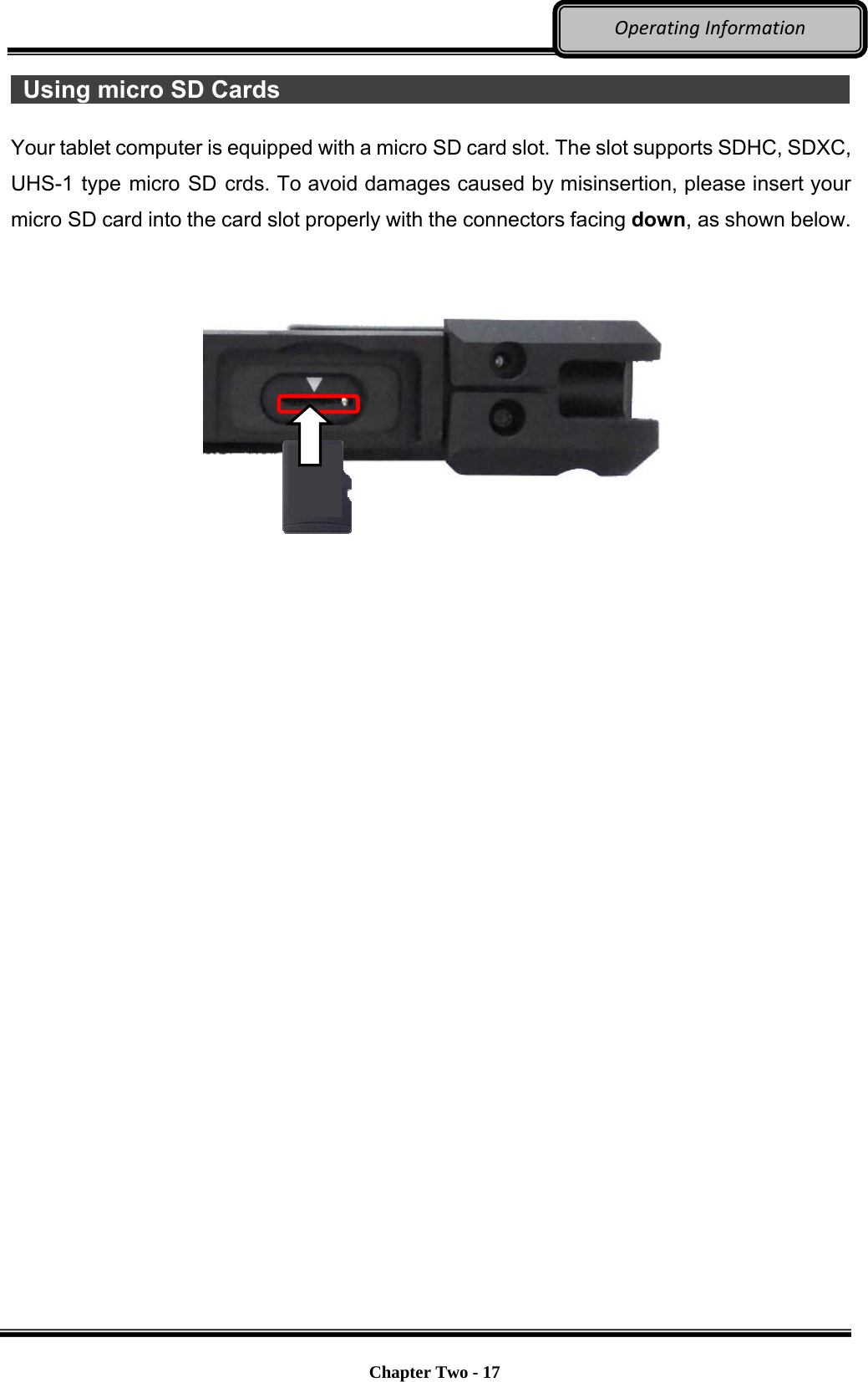
![Chapter Two - 13 OperatingInformation 1st Layer buttons Before using the functions of 1st layer buttons, please make sure that the [Fn Lock] indicator is OFF. A list of functions of 1st layer buttons is provided below for operational reference: Button Description Increase brightness Decrease brightness Turn the screen clockwise Increase volume Decrease volume Esc For functions such as cancel or interrupt running programs, or for BIOS Selection Ctrl Press and hold Ctrl with other keys for combination key functions Alt Press and hold Alt with other keys for combination key functions Enter Command for operation Del The function of deletion](https://usermanual.wiki/MilDef-Crete/DS11/User-Guide-2718096-Page-25.png)
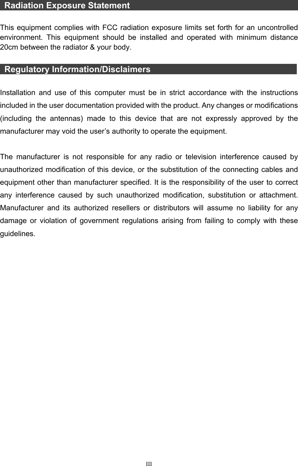
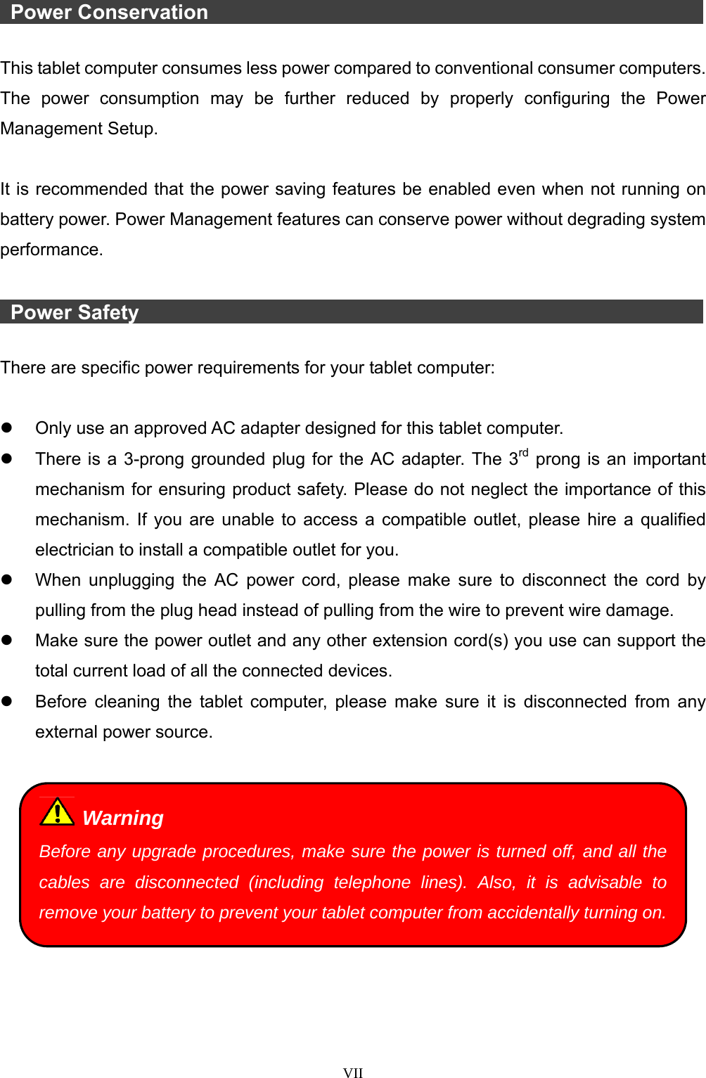
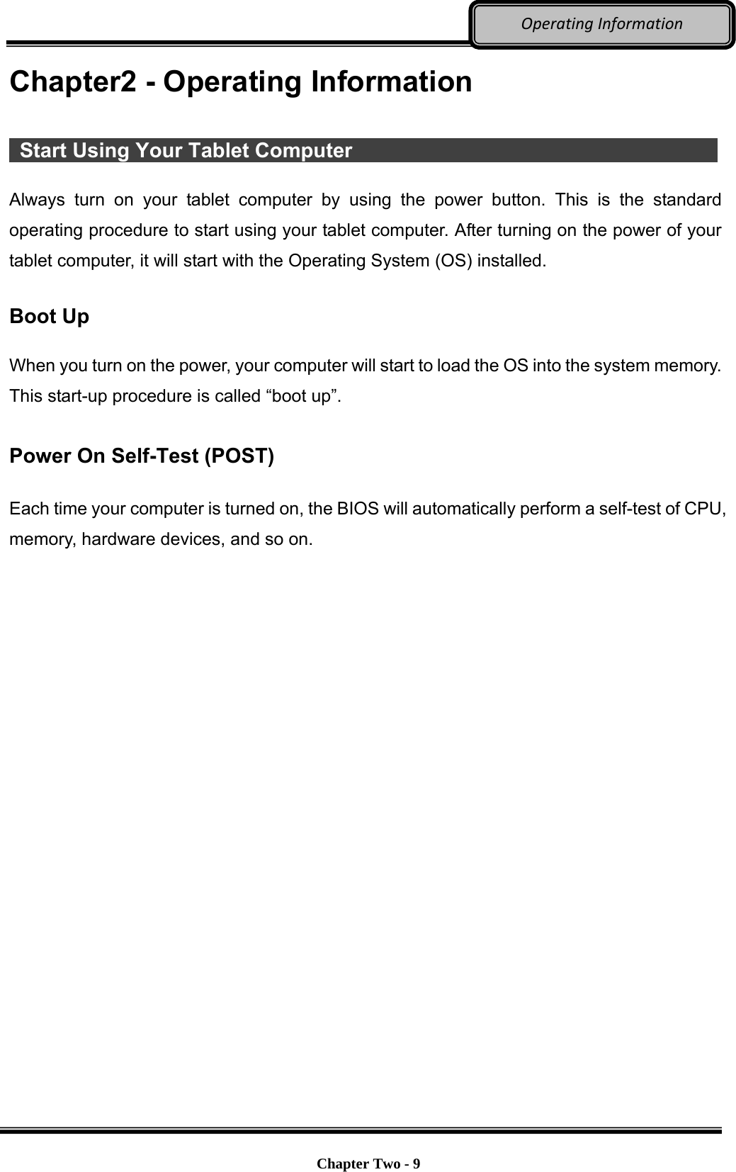
![Chapter Two - 14 OperatingInformation 2nd Layer Buttons To perform 2nd layer buttons (functions printed in blue on buttons), press the [Fn Lock] button first, and the Fn Lock indicator will be on, and then press the buttons you would like to perform. A list of functions on 2nd layer button is provided below for operational reference: Button Description [A1]: Windows 8.1: Default: Simulate right click the mouse on the start button Windows 7: Default: Windows Mobility Center [A2]: Default: Open the Ease of Access Center [A3]: Default: Enter into Lock Screen Plus (+) Sign For BIOS value change or other "plus" functions Minus (-) Sign For BIOS value change or other "minus" functions Up Arrow (↑) Key For BIOS Select or other "move up" options Down Arrow (↓) Key For BIOS Select or other "move down" options Left Arrow (←) Key For BIOS Select or other "move left" options Right Arrow (→) Key For BIOS Select or other "move right" options Tab Tabulation Note: When press Fn Lock key, you can only perform the functions printed in blue](https://usermanual.wiki/MilDef-Crete/DS11/User-Guide-2718096-Page-26.png)
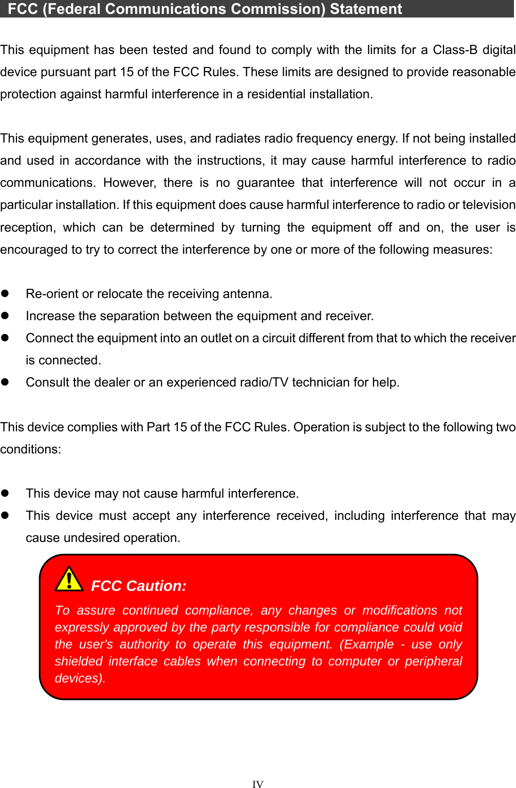
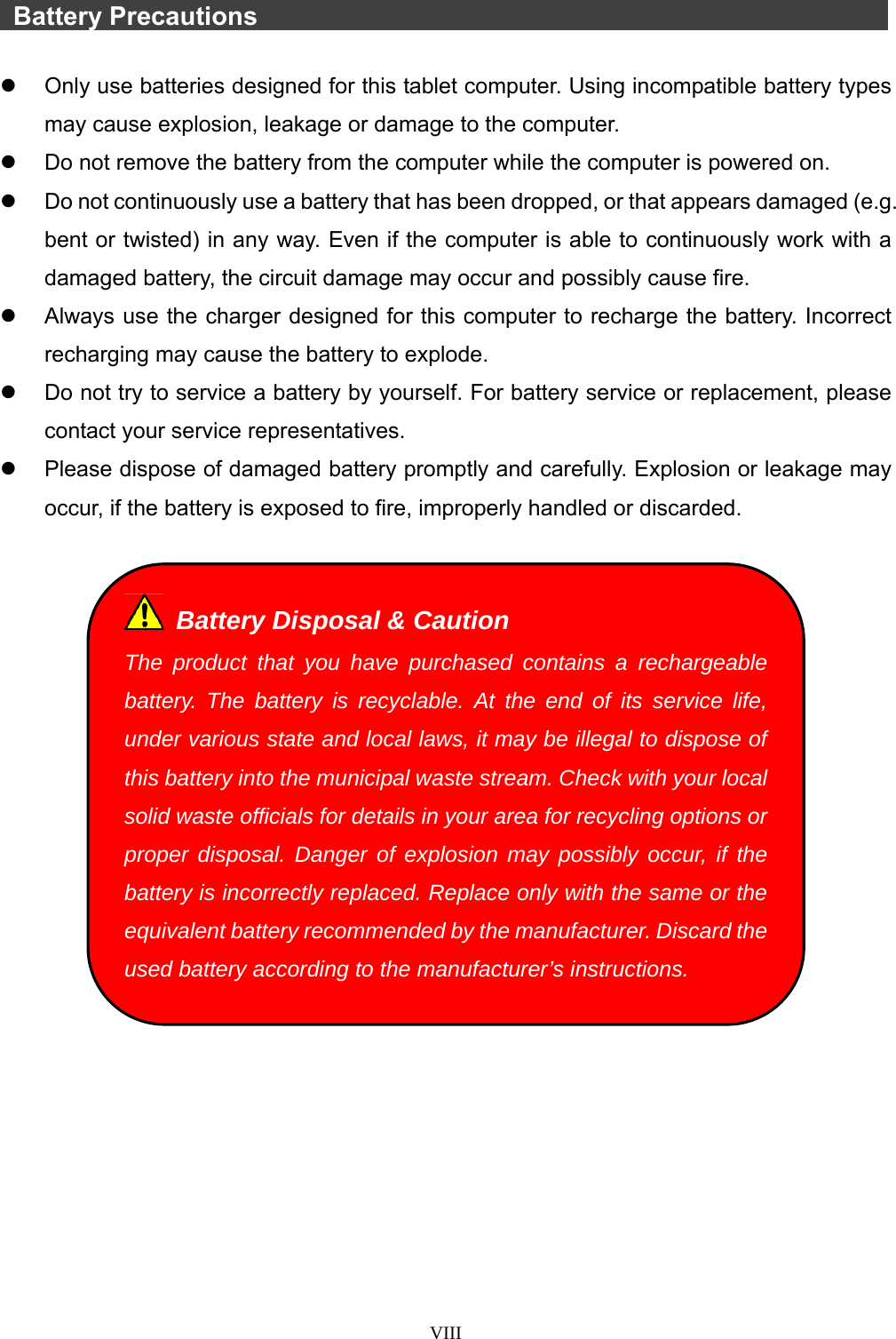
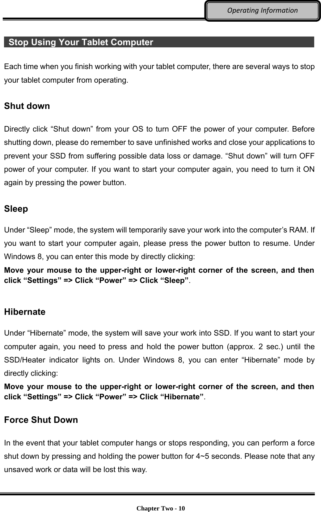
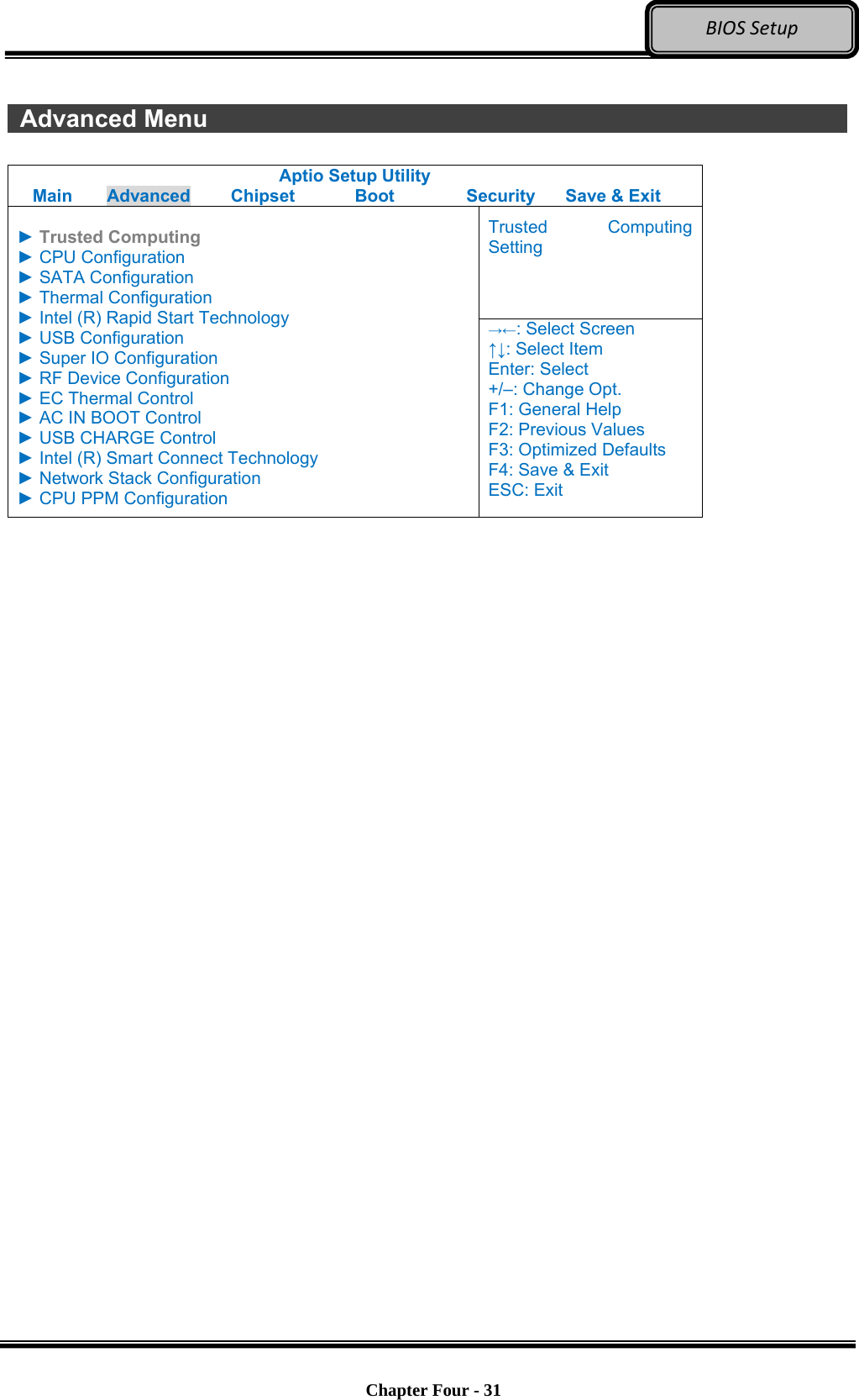
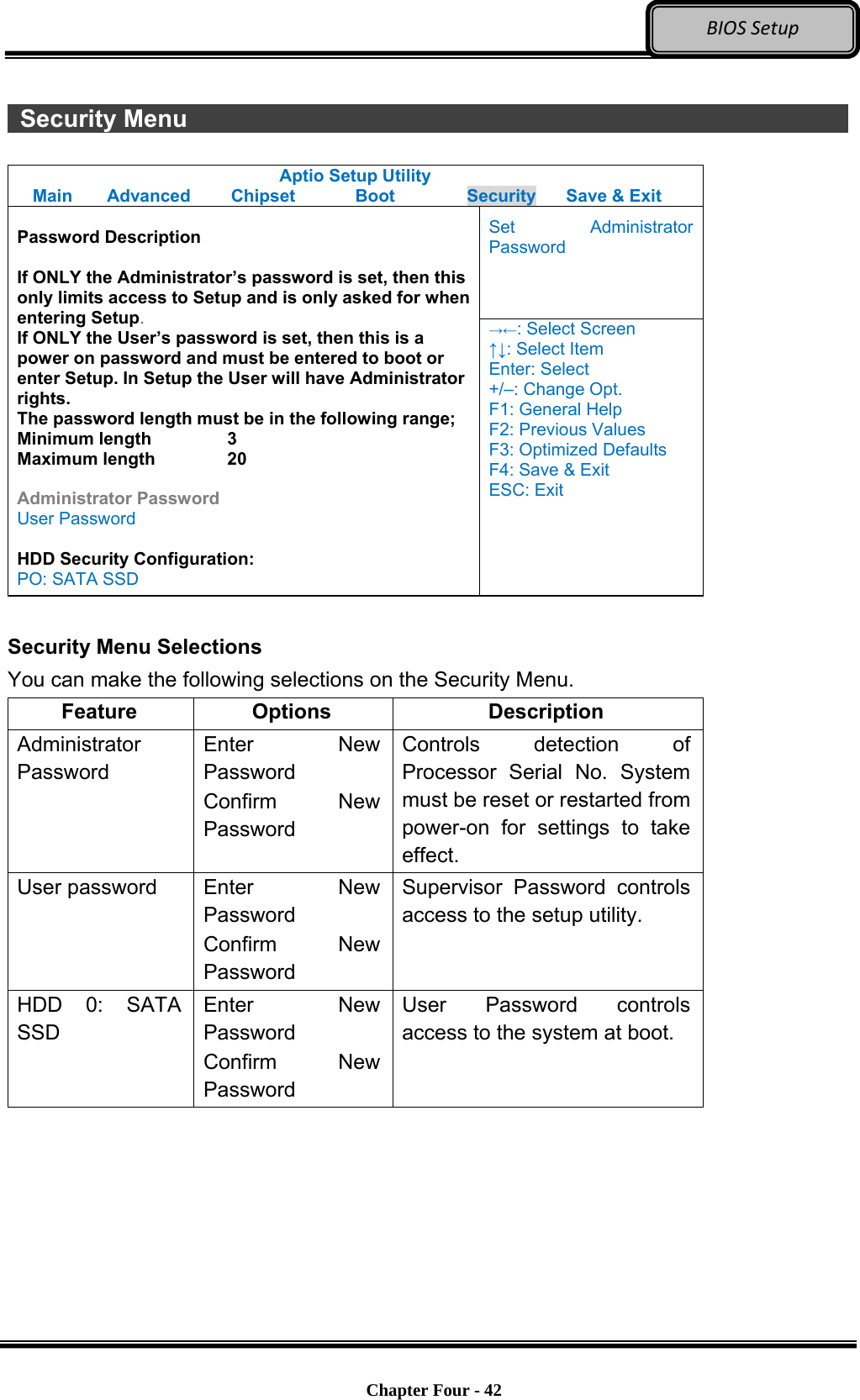
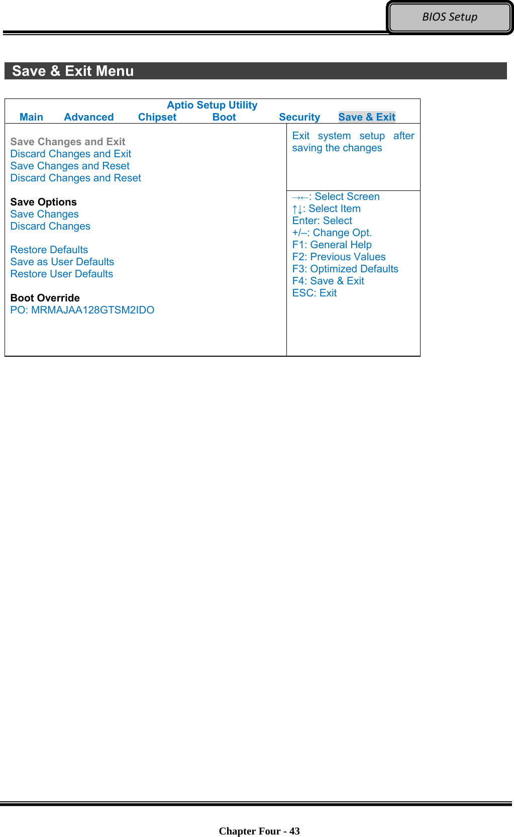
![Optional Devices Chapter Four - 30 BIOSSetupChapter 4 - BIOS Setup Press [F2] + [Delete] at boot up to enter BIOS setup. Use arrow keys to select options and [+/-] to modify them. When finished, move to “Exit” and press [Enter] then confirm save by pressing [Y]. Main Menu Aptio Setup Utility Main Advanced Chipset Boot Security Save & Exit Choose the system default language BIOS Information BIOS Vendor Core Version Compliancy Project Version Build Date and Time EC Version System Language [English] System Date [Wed 06/19/2013] System Time [16:19:20] Access Level Administrator →←: Select Screen ↑↓: Select Item Enter: Select +/–: Change Opt. F1: General Help F2: Previous Values F3: Optimized Defaults F4: Save & Exit ESC: Exit Main Menu Selections You can make the following selections on the Main Menu. Use the sub-menus for other selections. Feature Options Description System Date MM/DD/YYYY Set the system date Month, Day, Year. System Time HH:MM:SS Set the system time Hour, Minute, Second. Note: The contents may vary depending on computer configurations. Incorrect settings may cause system malfunction. To correct it, restore the Optimized Defaults with F3.](https://usermanual.wiki/MilDef-Crete/DS11/User-Guide-2718096-Page-42.png)
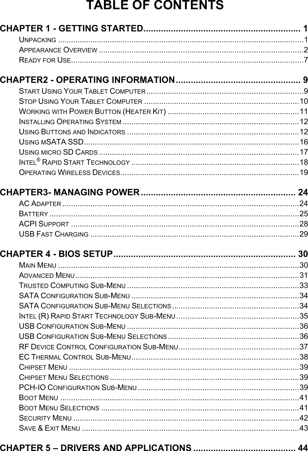
![Optional Devices Chapter Four - 33 BIOSSetup Trusted Computing Sub-Menu Aptio Setup Utility Advanced Enables or Disables BIOS support for security device. O.S. will not show Security Device. TCG EFI protocol and INT1A interface will not be available. Configuration Security Device Support [Disable] Current Status Information SUPPORT TURNED OFF →←: Select Screen ↑↓: Select Item Enter: Select +/–: Change Opt. F1: General Help F2: Previous Values F3: Optimized Defaults F4: Save & Exit ESC: Exit](https://usermanual.wiki/MilDef-Crete/DS11/User-Guide-2718096-Page-45.png)
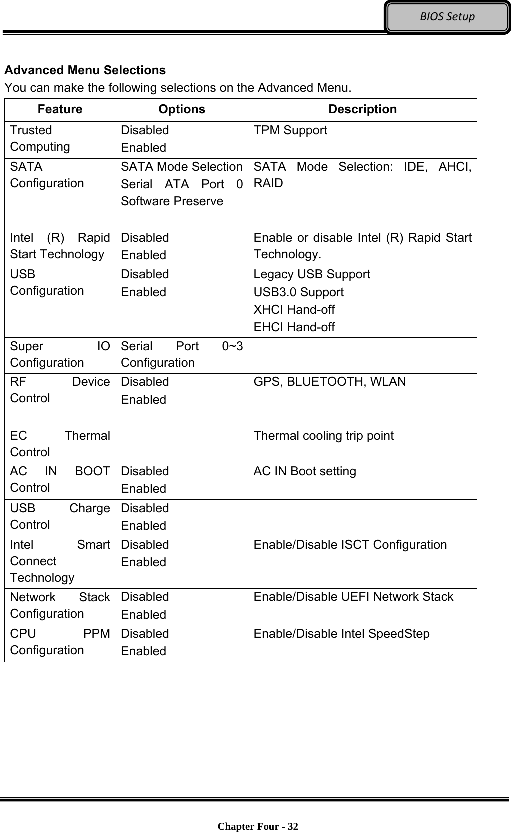
![Optional Devices Chapter Four - 34 BIOSSetup SATA Configuration Sub-Menu Aptio Setup Utility Advanced Determine how SATA controller(s) operate. SATA Mode Selection [AHCI] SATA Test Mode [Disabled] Aggressive LPM Support [Enabled] SATA Controller Speed [Gen3] Serial ATA Port 0 Empty Software Preserve Unknown Serial ATA Port 1 Empty Software Preserve Unknown Serial ATA Port 2 SATA SSD (120.0 Software Preserve SUPPORTED →←: Select Screen ↑↓: Select Item Enter: Select +/–: Change Opt. F1: General Help F2: Previous Values F3: Optimized Defaults F4: Save & Exit ESC: Exit SATA Configuration Sub-Menu Selections You can make the following selections on the SATA configuration sub-menu. Feature Options Description SATA Mode Selection IDE AHCI RAID Determine how SATA controller(s) operate SATA Test Mode Disabled Enabled Enable or disable Test Mode Aggressive LPM Support Disabled Enabled Enable PCH to aggressively enter link power state SATA Controller Speed Gen1 Gen2 Gen3 Indicates the maximum speed the SATA controller can support Port 0 Disabled Enabled Enable or Disable SATA Port Hot Plug Disabled Enabled Designates this port as Hot Pluggable](https://usermanual.wiki/MilDef-Crete/DS11/User-Guide-2718096-Page-46.png)
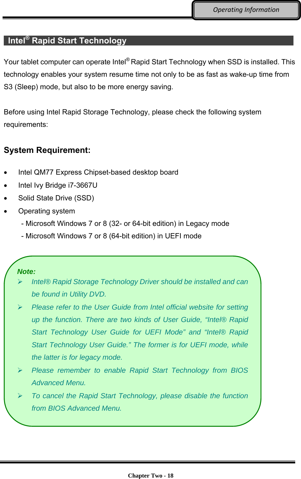
![Optional Devices Chapter Four - 35 BIOSSetupIntel (R) Rapid Start Technology Sub-Menu Aptio Setup Utility Advanced Enables or disable Intel (R) Rapid Start Technology Intel (R) Rapid Start Technology [Disabled] →←: Select Screen ↑↓: Select Item Enter: Select +/–: Change Opt. F1: General Help F2: Previous Values F3: Optimized Defaults F4: Save & Exit ESC: Exit](https://usermanual.wiki/MilDef-Crete/DS11/User-Guide-2718096-Page-47.png)
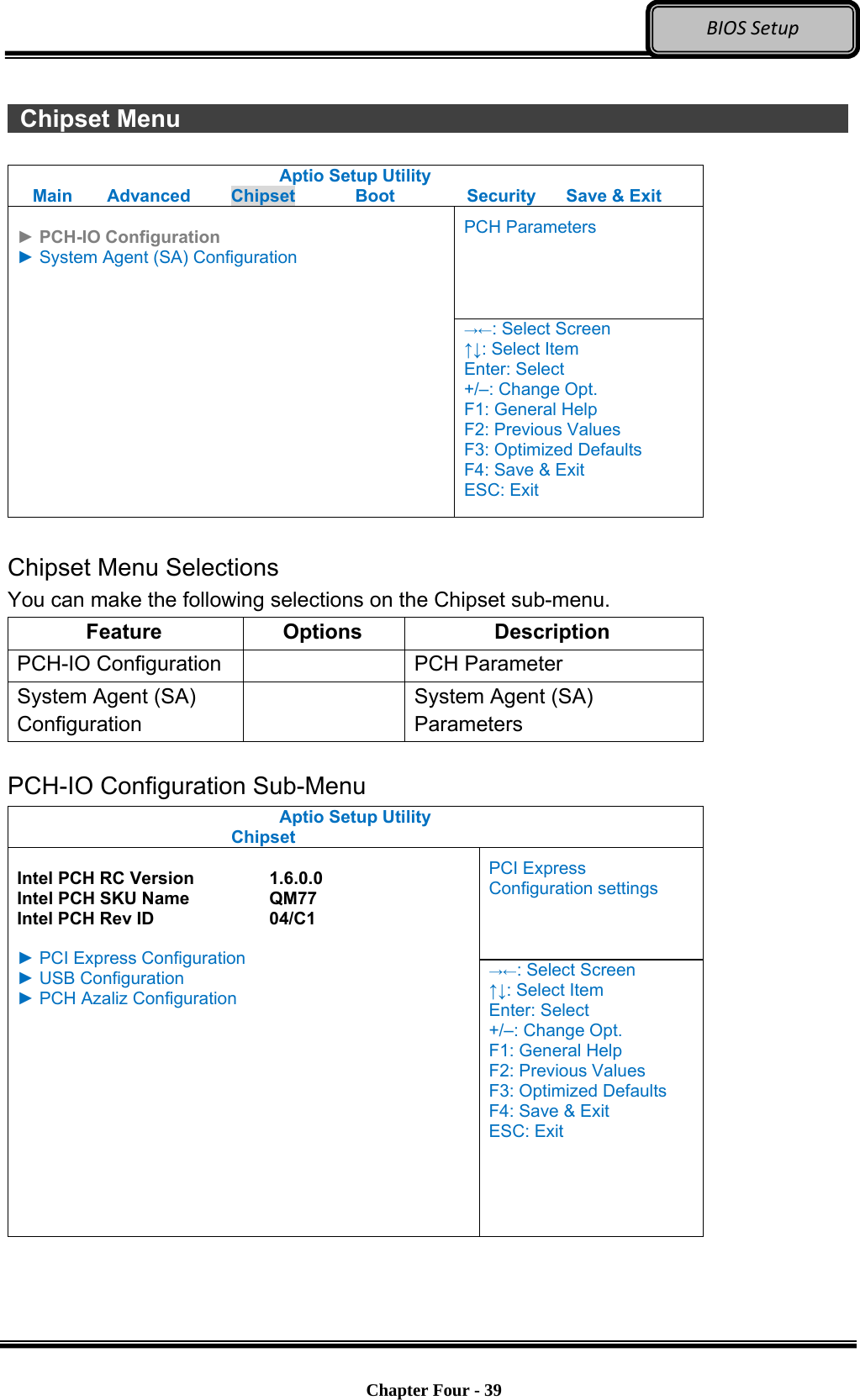
![Optional Devices Chapter Four - 36 BIOSSetup USB Configuration Sub-Menu Aptio Setup Utility Advanced Enables Legacy USB support. AUTO option disables legacy support if no USB devices are connected. Disable option will keep USB devices available only for EFI applications USB Configuration USB Devices: 1 point Legacy USB Support [Enabled] USB3.0 Support [Enabled] XHCI Hand-off [Enabled] EHCI Hand-off [Disabled] →←: Select Screen ↑↓: Select Item Enter: Select +/–: Change Opt. F1: General Help F2: Previous Values F3: Optimized Defaults F4: Save & Exit ESC: Exit USB Configuration Sub-Menu Selections You can make the following selections on the USB configuration sub-menu. Feature Options Description Legacy USB enabled Disabled Enabled Enables Legacy USB support. AUTO option disables legacy support if no USB devices are connected. DISABLE option will keep USB devices available only for EFI applications. Usn3.0 Support Disabled Enabled Enable/Disable USB3.0 (XHCI) Controller support. XHCI Hand-off Disabled Enabled This is a workaround for OSes without XHCI hand-off support. This XHCI ownership change should be claimed by XHCI driver. EHCI Hand-off Disabled Enabled This is a workaround for OSes without EHCI hand-off support. This EHCI ownership change should be claimed by EHCI driver.](https://usermanual.wiki/MilDef-Crete/DS11/User-Guide-2718096-Page-48.png)
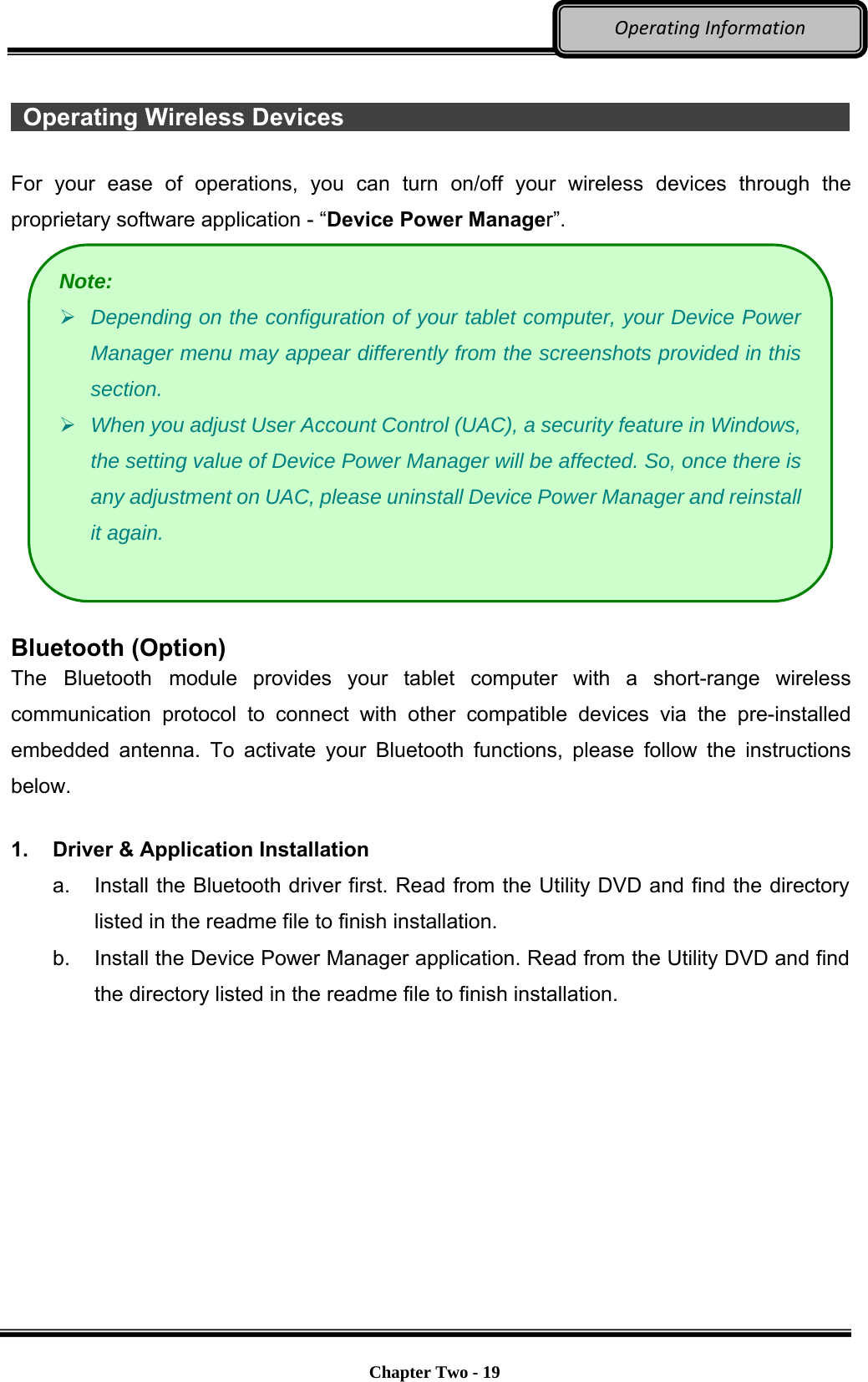
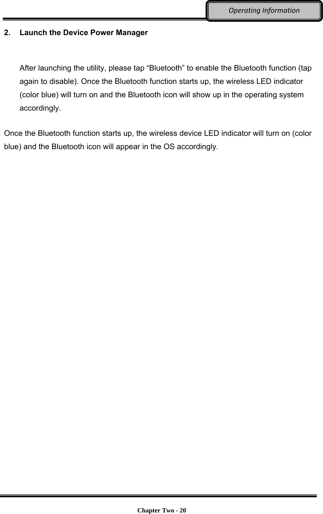
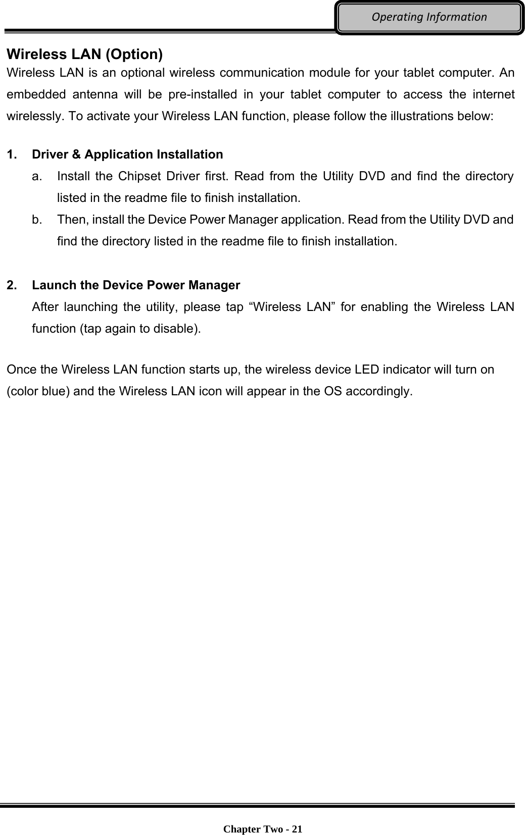
![Optional Devices Chapter Four - 37 BIOSSetupRF Device Control Configuration Sub-Menu Aptio Setup Utility Advanced RF Device Control Setting RF Device Control GPS STATUS Present GPS [Enabled] BT STATUS Present BLUETOOTH [Enabled] WLAN STATUS Present WLAN [Enabled] →←: Select Screen ↑↓: Select Item Enter: Select +/–: Change Opt. F1: General Help F2: Previous Values F3: Optimized Defaults F4: Save & Exit ESC: Exit RF Device Control Configuration Sub-Menu Selections You can make the following selections on the RF Security Control sub-menu. Feature Options Description Wireless LAN Disabled Enabled Wireless Lan Control Enabled Wireless function GPS Disabled Enabled GPS Control Enabled GPS function BlueTooth Disabled Enabled BlueTooth Control Enabled Blue Tooth function](https://usermanual.wiki/MilDef-Crete/DS11/User-Guide-2718096-Page-49.png)
![Optional Devices Chapter Four - 38 BIOSSetup EC Thermal Control Sub-Menu Aptio Setup Utility Advanced EC Thermal Control Setting EC Thermal Control User mode [Normal mode - 87 C] →←: Select Screen ↑↓: Select Item Enter: Select +/–: Change Opt. F1: General Help F2: Previous Values F3: Optimized Defaults F4: Save & Exit ESC: Exit EC Thermal Control Sub-Menu Selections You can make the following selections on the EC Thermal Control sub-menu. Feature Options Description User mode Tablet mode – 79 C Normal mode – 87 C High Performance mode – 95 C](https://usermanual.wiki/MilDef-Crete/DS11/User-Guide-2718096-Page-50.png)
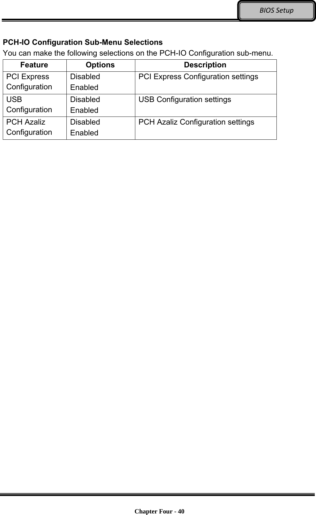
![Optional Devices Chapter Four - 41 BIOSSetup Boot Menu Aptio Setup Utility Main Advanced Chipset Boot Security Save & Exit Set boot mode LEGACY/UEFI Boot mode select [Legacy] Boot Option Priorities Boot Option #1 [Hard Disk: SATA SSD...] Boot Option #2 [CD/DVD] Boot Option #3 [USB Hard Disk] Boot Option #4 [USB CD/DVD] Boot Option #5 [USB Key] Boot Option #6 [USB Floppy] Boot Option #7 [Network] ► CSM parameters ► Hard Disk Drive BBS Priorities →←: Select Screen ↑↓: Select Item Enter: Select +/–: Change Opt. F1: General Help F2: Previous Values F3: Optimized Defaults F4: Save & Exit ESC: Exit The system will try to boot from device on top then the 2nd and so on. If there is more than one device in each category, only the device on top of sub-menu can boot up. Boot Menu Selections You can make the following selections on the Boot menu. Feature Options Description Boot mode select LEGACY UEFI Select boot mode LEGACY/UEFI Boot Option #1 Sets the system boot order Boot Option #2 Sets the system boot order CSM parameters OpROM execution, boot options filter, etc. Hard Drive BBS Priorities Set the Boot Device Priority sequence from available Hard Disk Drives](https://usermanual.wiki/MilDef-Crete/DS11/User-Guide-2718096-Page-53.png)
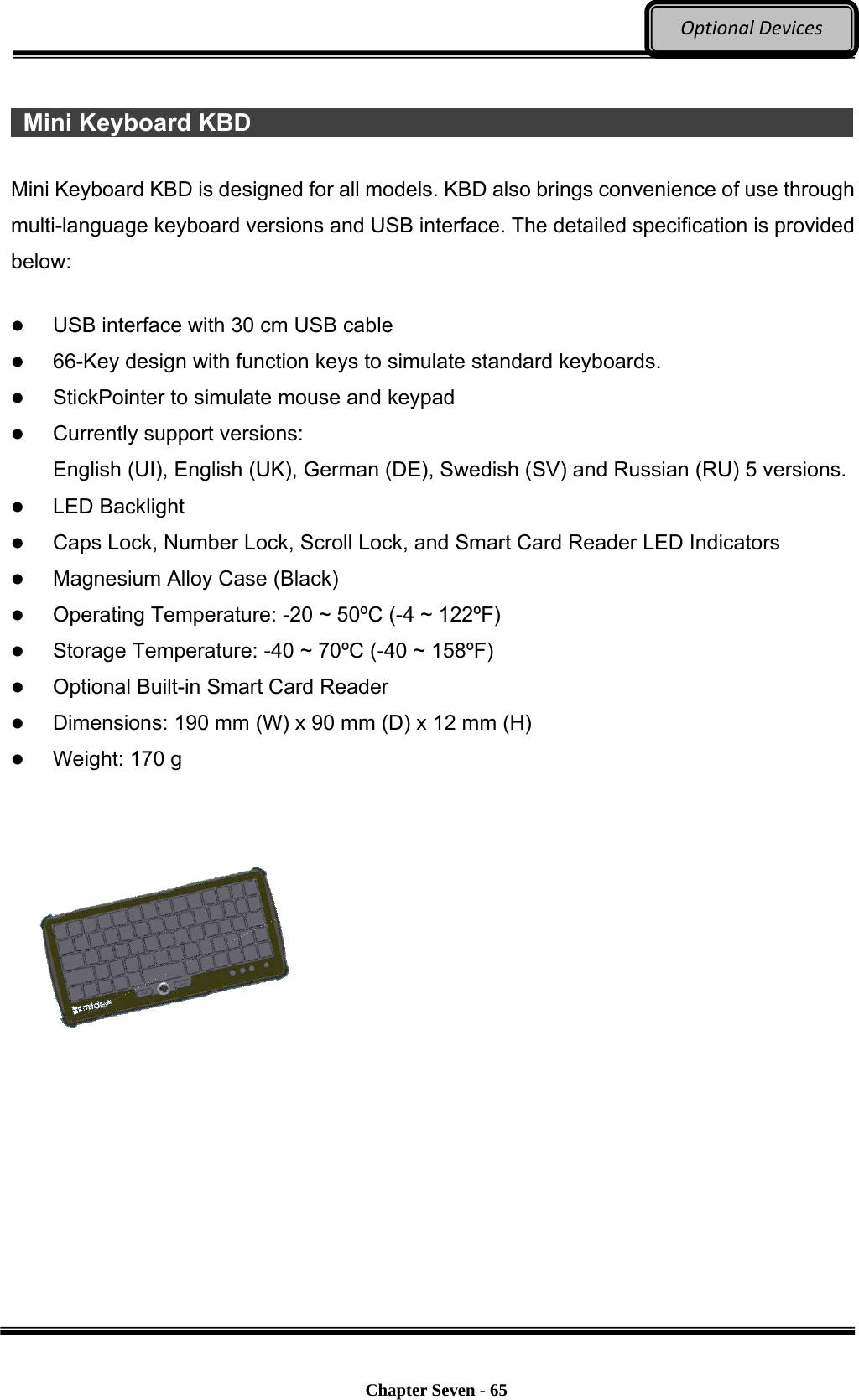
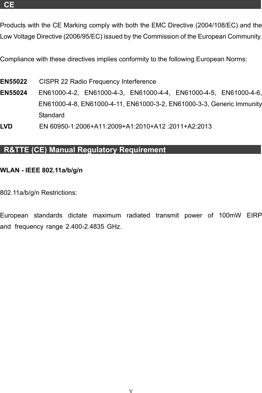
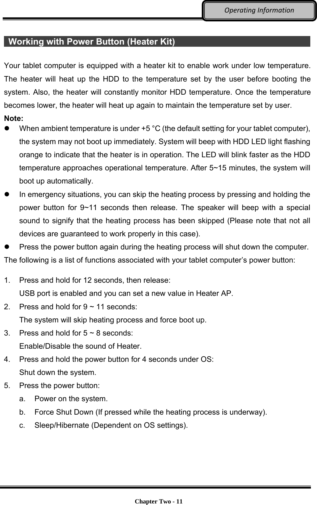
![Chapter Seven - 64 OptionalDevices External USB Keyboard An optional 89-key external USB keyboard with LED backlight and IP rating of IP54 is available for your tablet computer. The detailed specification is provided below: 89-key layout emulates 101/102-key KB Life: >1 million times, water/dust protection up to IP54 Back-light illumination (backlight device: green LED) PS/2 compatible Trackpoint and mouse buttons Dimensions: 323.4 mm (W) x 172 mm (D) x 25 mm (H) Weight: 1.1 kg Track point The track point is functionally equivalent to a mouse. Pushing the track point may move the cursor on the screen. The 2 buttons act same as mouse buttons. Backlight Press [I-O] key for approximately 1 second turns keyboard backlight ON or OFF.](https://usermanual.wiki/MilDef-Crete/DS11/User-Guide-2718096-Page-76.png)