Millennial Net URM-M-2400 MeshNode User Manual
Millennial Net MeshNode
UserManual.wiki
>
Millennial Net
>
URM M 2400 User Manual
User manual
Navigation menu
Upload a User Manual
Namespaces
Wiki Guide
HTML
PDF
Info
Views
User Manual
Discussion / Help
Navigation


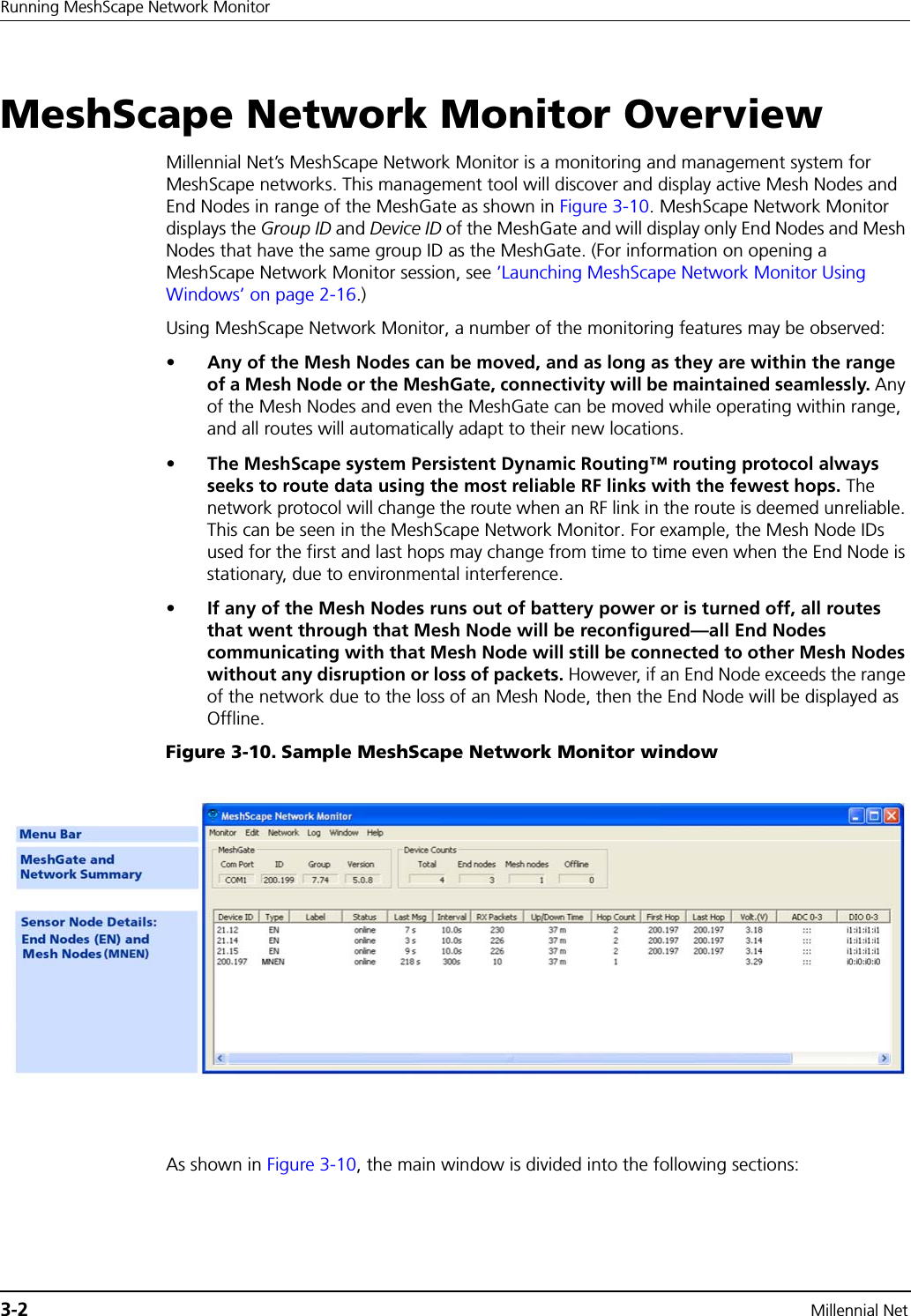

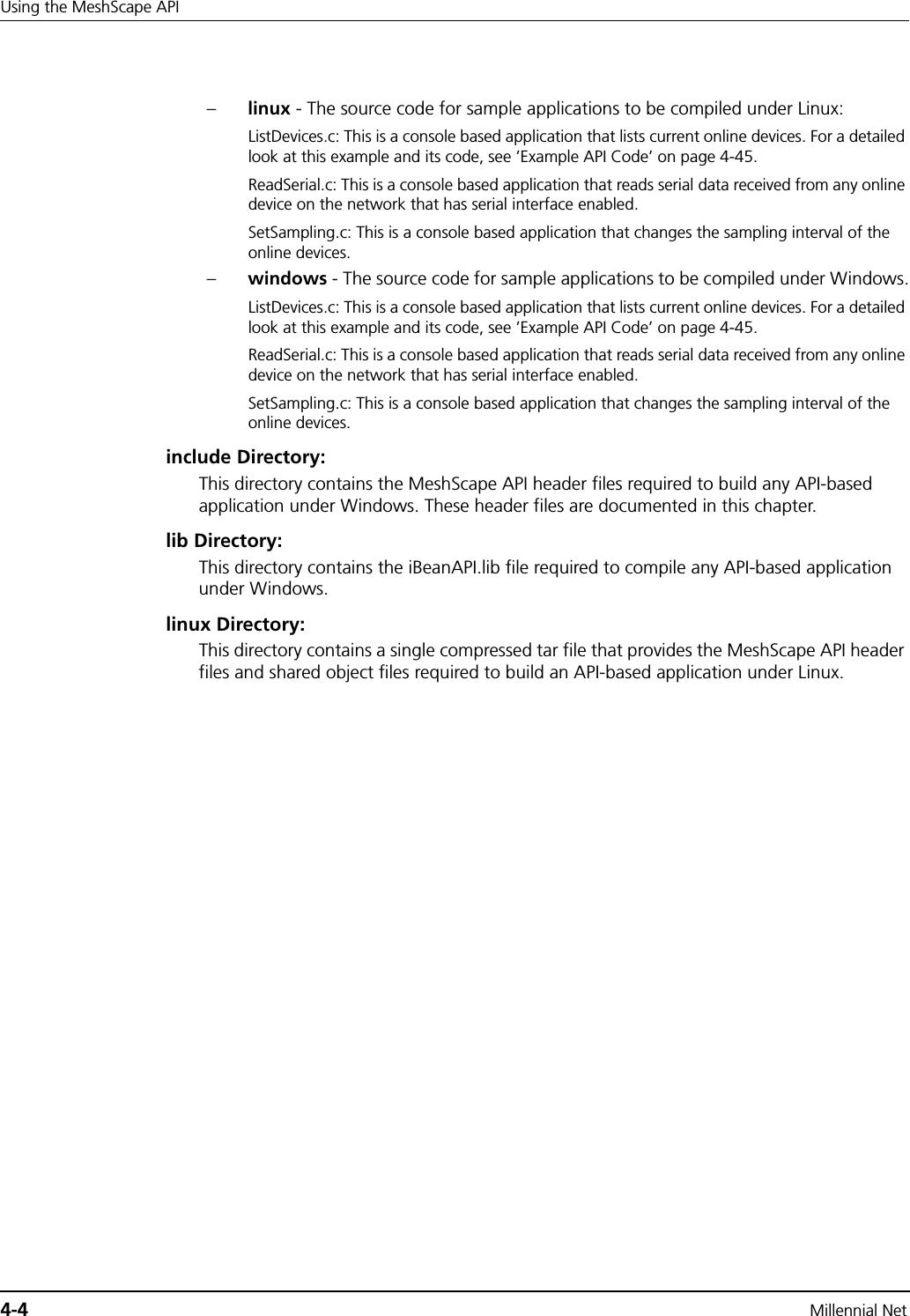
![RK-5424-5 Reference Kit User’s Guide 4-7iBeanAPI.hiBeanAPI.hData Structures1. ibApi_APIHANDLEtypedef ibApi_INT32 ibApi_APIHANDLE;This handle represents an API session. It is created by ibApi_Open() and used by most of the other API functions. 2. ibApi_RESULTtypedef ibApi_INT32 ibApi_RESULT;The API functions are standardized to return the value ibApi_RESULT, which is a signed 32-bit integer. If the integer is negative, then it is an error code such as ibApi_RESULT_ERR_INVALIDHANDLE or ibApi_RESULT_ERR_NOTPERMITTED. (See iBeanAPI.h for a full listing of error codes.) Otherwise, the result can be ibApi_RESULT_SUCCESS or a non-negative value specific to the particular function. 3. ibApi_GROUPIDstruct ibApi_GROUPID_s { ibApi_UINT8 words[ibApi_GROUPID_SIZE];};typedef struct ibApi_GROUPID_s ibApi_GROUPID;The group ID is a 32-bit address that is used to identify a specific network of i-Bean devices and is shared by all the devices within the network. (In the current implementation, each MeshScape system group can only have one MeshGate.)The API functions are standardized to return the value ibApi_RESULT, which is a signed 32-bit integer. If the integer is negative, then it is an error code such as ibApi_RESULT_ERR_INVALIDHANDLE or ibApi_RESULT_ERR_NOTPERMITTED. (See iBeanAPI.h for a full listing of error codes.) Otherwise, the result can be ibApi_RESULT_SUCCESS or a non-negative value specific to the particular function. 4. ibApi_DEVICEIDstruct ibApi_DEVICEID_s { ibApi_UINT8 words[ibApi_DEVICEID_SIZE];};typedef struct ibApi_DEVICEID_s ibApi_DEVICEID;The device ID is a 64-bit address that uniquely identifies an i-Bean network component such as end node, mesh node, or gateway.](https://usermanual.wiki/Millennial-Net/URM-M-2400/User-Guide-616713-Page-83.png)
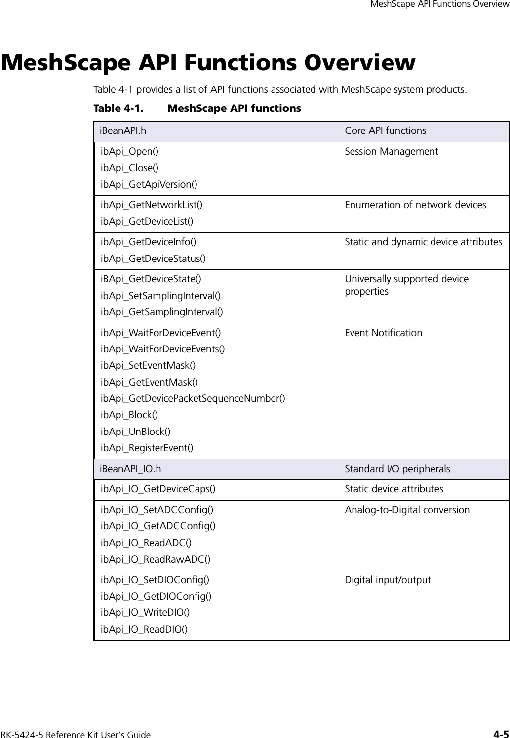
![RK-5424-5 Reference Kit User’s Guide 4-9iBeanAPI.h8. ibApi_DEVICEINFO#define ibApi_MAX_VERSION_STRLEN 32struct ibApi_DEVICEINFO_s {ibApi_UINT16 struct_size;ibApi_DEVICETYPE device_type;ibApi_CHAR hardware_version[ibApi_MAX_VERSION_STRLEN];ibApi_CHAR firmware_version[ibApi_MAX_VERSION_STRLEN];};typedef struct ibApi_DEVICEINFO_s ibApi_DEVICEINFO;This data structure is used by ibApi_GetDeviceInfo() to report static device attributes that are fixed at manufacturing time.Structure Fields:struct_size The value sizeof (ibApi_DEVICEINFO) should be assigned to this field prior to calling ibApi_GetDeviceInfo(). This allows future versions of the API to extend the struct without breaking binary compatibility.device_type The type of the device (end node, mesh node, etc.).hardware_version These two fields report the firmware and hardware version strings for firmware_version various network devices, which are useful for diagnostic purposes. An empty string may be assigned if the device does not support version reporting. 9. ibApi_DEVICESTATEenum ibApi_DEVICESTATE_e {ibApi_DEVICESTATE_OFFLINE,ibApi_DEVICESTATE_ONLINE,ibApi_DEVICESTATE_REFRESHING,};typedef ibApi_UINT16 ibApi_DEVICESTATE;These functions are used with ibApi_GetDeviceState(). When a command is issued to modify a network device, a series of network communications must occur before the change will take effect. During this time period the said to be “refreshing”, and the actual device state may be different from values visible to the API. The refresh time depends on many factors such as sampling interval, traffic level, network topology, etc.](https://usermanual.wiki/Millennial-Net/URM-M-2400/User-Guide-616713-Page-85.png)
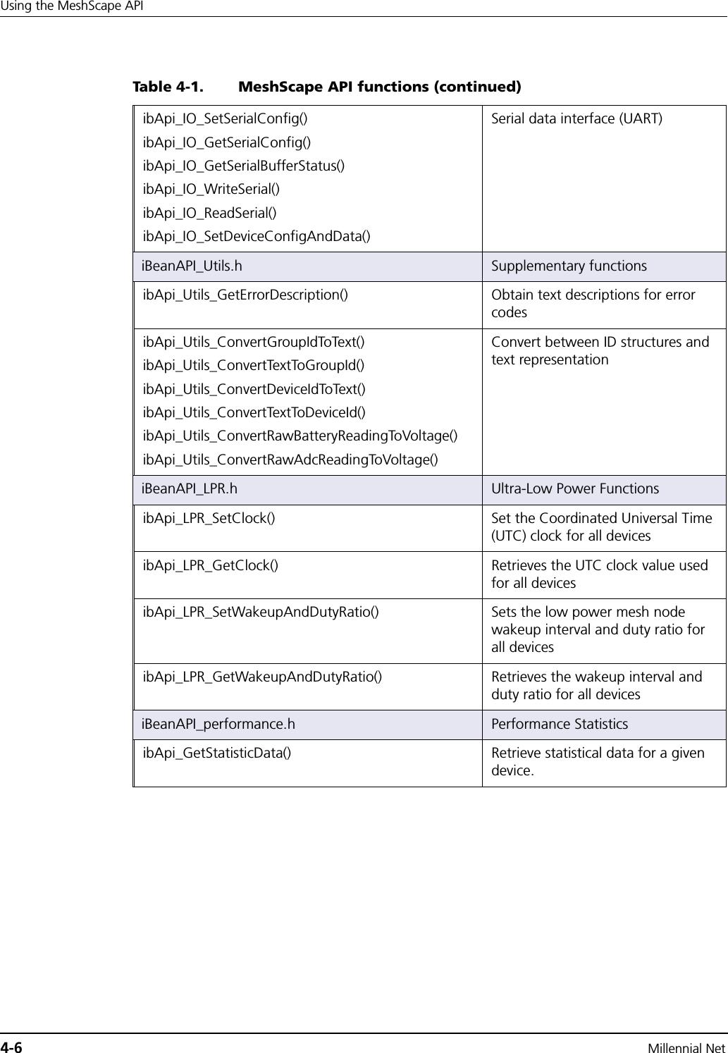
![RK-5424-5 Reference Kit User’s Guide 4-11iBeanAPI.h11. ibApi_EVENTMASKtypedef ibApi_UINT32 ibApi_EVENTMASK;#define ibApi_MAX_SERIAL_DATA_SIZE 255#define ibApi_MAX_ADC_DATA_CHANNELS 4#define ibApi_MAX_DIO_DATA_CHANNELS 4#define ibApi_UNDEFINED_FIELD_VALUE 0xFF #define ibApi_Serial_Receive_EVENT_DATA_TYPE 0x11#define ibApi_ADC_EVENT_DATA_TYPE 0x22#define ibApi_DIO_EVENT_DATA_TYPE 0x33#define ibApi_Device_State_EVENT_DATA_TYPE 0x44#define ibApi_Sampling_Interval_EVENT_DATA_TYPE 0x55#define ibApi_Battery_Level_EVENT_DATA_TYPE 0x66#define ibApi_Network_EVENT_DATA_TYPE 0x77#define ibApi_Heartbeat_EVENT_DATA_TYPE 0x88Use this structure to identify events passed to event callbacks.12. ibApi_CALLBACK_DATAtypedef ibApi_UINT8 ibApi_CALLBACK_DATA;ibApi_CALLBACK_DATA is a pointer which must be cast to one of the data types that are described in the following sections.13. ibApi_ADC_EVENT_DATAtypedef struct {ibApi_UINT8 dataType; // Must be first!ibApi_UINT8 status; // 1=enabled, 0=disabled, 0xFF=undefinedibApi_DEVICEID deviceID;ibApi_UINT8 channelMask; // 0 = no dataibApi_UINT8 reserved; // for alignmentibApi_FLOAT channelData[8];} This data structure will be passed to event callbacks to convey information about ADC events.Use the first argument ibApi_EVENTMASK to determine how to cast the callback data.](https://usermanual.wiki/Millennial-Net/URM-M-2400/User-Guide-616713-Page-87.png)
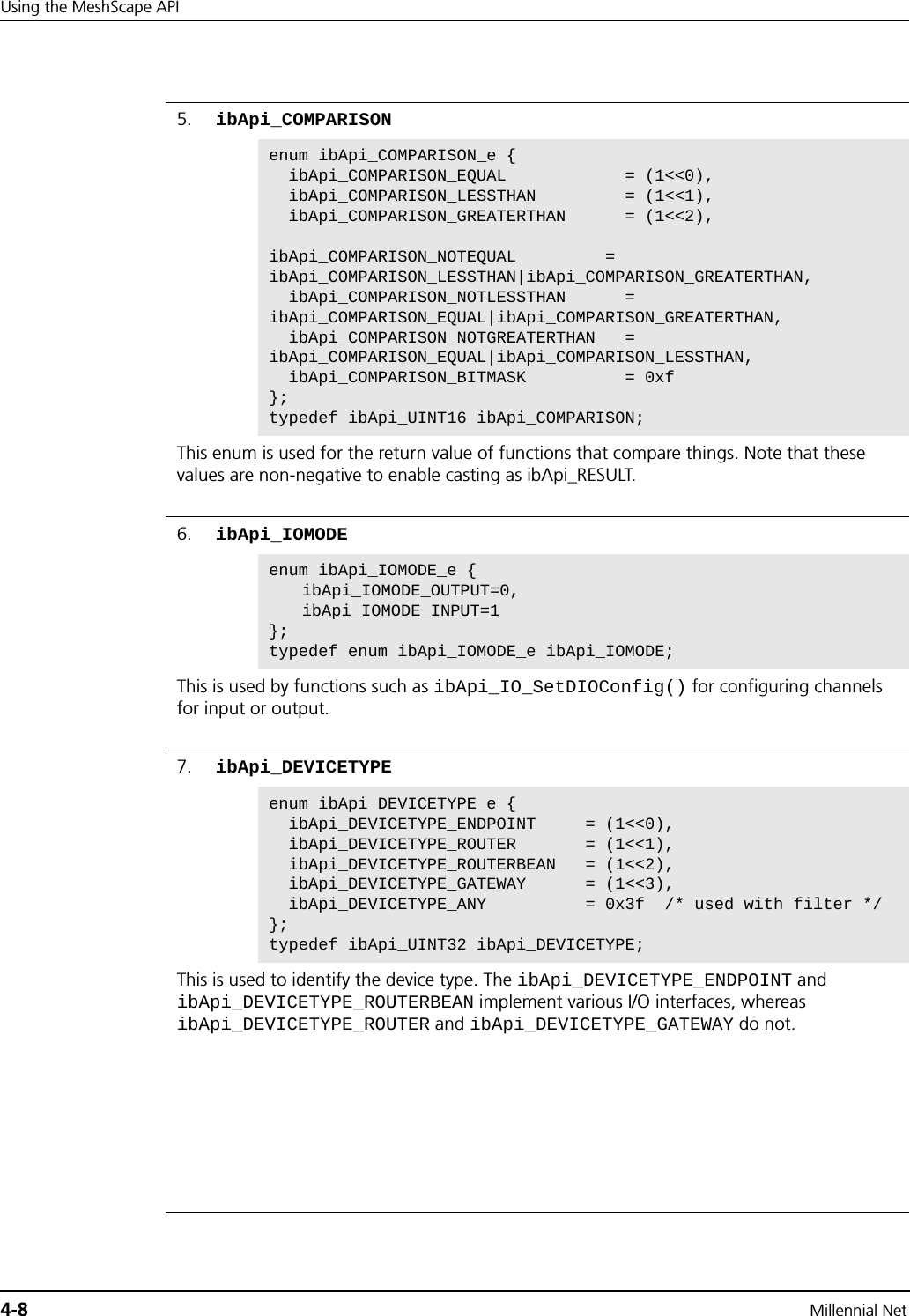
![RK-5424-5 Reference Kit User’s Guide 4-13iBeanAPI.h17. ibApi_Serial_Receive_EVENT_DATAtypedef struct {ibApi_UINT8 dataType; // Must be first!ibApi_UINT8 serialState; // 0xFF=undefinedibApi_DEVICEID deviceID;ibApi_UINT8 serialDataSize;ibApi_UINT8 serialSequence;ibApi_UINT8 serialData[ibApi_MAX_SERIAL_DATA_SIZE];} This data structure will be passed to event callbacks to convey information about serial receive events.Use the first argument ibApi_EVENTMASK to determine how to cast the callback data.18. ibApi_Battery_Level_EVENT_DATAtypedef struct {ibApi_UINT8 dataType; // Must be first!ibApi_UINT8 reserved; // for alignementibApi_DEVICEID deviceID;ibApi_FLOAT batteryLevel;} This data structure will be passed to event callbacks to convey information about battery level events.Use the first argument ibApi_EVENTMASK to determine how to cast the callback data. 19. ibApi_Network_EVENT_DATAtypedef struct {ibApi_UINT8 dataType; // Must be first!ibApi_UINT8 hopCount; ibApi_DEVICEID deviceID;ibApi_DEVICEID firstHopRouter;ibApi_DEVICEID lastHopRouter;}This data structure will be passed to event callbacks to convey information about network events.Use the first argument ibApi_EVENTMASK to determine how to cast the callback data.](https://usermanual.wiki/Millennial-Net/URM-M-2400/User-Guide-616713-Page-89.png)
![RK-5424-5 Reference Kit User’s Guide 4-15iBeanAPI.hFunctions1. ibApi_OpenibApi_FUNC ibApi_Open( ibApi_VERSION expected_version, ibApi_CONST ibApi_CHAR *server_type, ibApi_CONST ibApi_CHAR * connection_str );ibApi_Open( ) should be called to initialize the API before any other function is called. The "server_type" parameter specifies the type of connection, and connection_str contains various connection parameters that vary according to server type.Notes: For the current release, the server_type should always be "local", and the default connection string is"". These text strings are case-sensitive.You can change the default COM port and Baud rate using the "connection_str" parameters. The string format is “-p[n]|-B[baud rate]”, where n = (COM port number – 1). For example, to select COM port 2 with a baud rate of 115200, you should supply the connection_str “-p1 –B115200”. By default, the COM port is COM1 and the baud rate is 115200.Notes: The connection baud rate needs to be consistent between the host and the MeshGate gateway. The default baud rate on the gateway is 115200, so if ibApi_Open() changes the baud rate to a different number, the baud rate on the gateway also needs to be updated.To access the COM port setting on Linux platforms, you need to either have root permission or change the COM port permission to current user.Parameters:expected_version: (input) Should always be ibApi_EXPECTED_VERSION.server_type: (input) "local" (Only valid setting for this release).connection_str: (input) "" (NULL string to set to default values).Return Value:An ibApi_APIHANDLE value if successful, or an error code (<0) if not. 2. ibApi_CloseibApi_FUNC ibApi_Close( ibApi_APIHANDLE api_hdl );This disconnects from the server and releases the API resources. This should be called before your application exits to avoid resource leaks.Parameter:api_hdl: (input) API handle returned from ibApi_Open() Return Value:An ibApi_RESULT_SUCCESS if successful, error code (<0) if not.](https://usermanual.wiki/Millennial-Net/URM-M-2400/User-Guide-616713-Page-91.png)
![4-16 Millennial NetUsing the MeshScape API3. ibApi_GetApiVersion()ibApi_FUNC ibApi_GetApiVersion ();This function returns the actual software version for the API, which can differ from ibApi_EXPECTED_VERSION if DLL’s are mixed.Return Value:An IbApi_VERSION value if successful, error code (<0) if not. 4. ibApi_GetNetworkList()ibApi_FUNC ibApi_GetNetworkList( ibApi_APIHANDLE api_hdl, ibApi_GROUPID networks[], ibApi_UINT32 networks_size);This retrieves a list of group ID’s for the networks managed by the server.Parameters:param api_hdl: (input) API handle returned from ibApi_Open()networks: (output) array of group ID’s that is managed by the servernetworks_size: (input) ibApi_INT32, maximum size for the network[]Return Value:The actual number of networks (which can exceed networks_size if the written data was truncated), or an error code (<0) if unsuccessful.](https://usermanual.wiki/Millennial-Net/URM-M-2400/User-Guide-616713-Page-92.png)
![RK-5424-5 Reference Kit User’s Guide 4-17iBeanAPI.h5. ibApi_GetDeviceList()ibApi_FUNC ibApi_GetDeviceList( ibApi_APIHANDLE api_hdl, ibApi_GROUPID network, ibApi_DEVICETYPE device_type ibApi_DEVICEID devices[], ibAPI_UINT32 devices_size );This function retrieves the ID’s of the devices in the network. The device_type parameter is a bitwise OR of the ibApi_DEVICETYPE constants that filters the result. (To retrieve all devices, use ibApi_DEVICETYPE_ANY.)Parameters:param api_hdl: (input) API handle returned from ibApi_Open().network: (input) Group ID of the network.device_type: (input) Device type filter.devices: (output) Pointer to an array of device IDs.devices_size: (input) Maximum number of device IDs that the devices array can hold.Return Value:The actual number of devices (which can exceed devices_size if the written data was truncated), or an error code (<0) if unsuccessful.6. ibApi_GetDeviceInfo()ibApi_FUNC ibApi_GetDeviceInfo( ibApi_APIHANDLE api_hdl, ibApi_DEVICEID device_id, ibApi_DEVICEINFO * device_info );This function retrieves various static device attributes that are predetermined at manufacturing time. Thus, these values only need to be queried once for a particular device. See ibApi_DEVICEINFO above for details.Note: To avoid memory corruption, the size of (ibApi_DECVICEINFO) must be allocated to the “struct_size” field prior to calling this function.Parameters:api_hdl: (input) API handle returned from ibApi_Open().device_id: (input) ID of device to be accessed.device_info: (output) Pointer to variable storing the result.Return Value:An ibApi_RESULT_SUCCESS if successful, error code (<0) if not.](https://usermanual.wiki/Millennial-Net/URM-M-2400/User-Guide-616713-Page-93.png)
![RK-5424-5 Reference Kit User’s Guide 4-33iBeanAPI_IO.h13. ibApi_IO_WriteSerial()ibApi_FUNC ibApi_IO_WriteSerial ( ibApi_APIHANDLE api_hdl, ibApi_DEVICEID device_id, ibApi_UINT8 buffer[], ibApi_UINT16 buffer_size );This function writes buffer_size bytes pointed to by the buffer pointer to the specified device handle. Prior to use, the ibApi_FIELDID_USERDATAMODE field must have been configured for serial operation. The specific contents of the user data block and its maximum size are application defined but must be equal to or smaller than that the maximum payload size supported. Maximum payload size supported is returned when the function ibApi_WriteSerialData() is called with buffer_size=0.Parameters:api_hdl: (input) API handle returned from ibApi_Open().device_id: (input) ID of the device to be accessed.buffer: (input) Pointer to packet to transmit.buffer_size: (input) Number of bytes in user data packet to transmit.Return Value:Bytes sent if successful, or an error code (<0) if not.](https://usermanual.wiki/Millennial-Net/URM-M-2400/User-Guide-616713-Page-109.png)
![4-34 Millennial NetUsing the MeshScape API14. ibApi_IO_ReadSerial()ibApi_FUNC ibApi_IO_ReadSerial ( ibApi_APIHANDLE api_hdl, ibApi_DEVICEID device_id, ibApi_UINT8 buffer[], ibApi_UINT16 buffer_size, ibApi_UINT8 *seq_num );For the given device, this retrieves the user data packet that arrived most recently. The ibApi_IO_SERIALMODE setting must have been previously something other than ibApi_IO_SERIALMODE_DISABLED. The input buffer holds a single packet (i.e., an arriving packet overwrites the previous one). Lost packets can be detected by gaps in the sequence numbers, which increment whenever a packet is received. If no new data is available, then the return value is 0.Parameters:api_hdl: (input) API handle returned from ibApi_Open().device_id: (input) ID of the device to be accessed.buffer[ ]: (output) Buffer to store the incoming user data packet.buffer_size: (input) Maximum size for buffer[ ].seq_num: (output) Pointer to sequence number identifying this packet, or NULL if this information is not needed.Return Value:Error code or the actual size of the result (which could exceed buffer_size if the written data was truncated) 15. ibApi_IO_SetDeviceConfigAndData()ibApi_FUNC ibApi_IO_SetDeviceConfigAndData( ibApi_APIHANDLE api_hdl, ibApi_DEVICEID device_id, ibApi_deviceSetConfigAndData *config_data );This function is used to make several configuration and data requests to a device at one time.Parameters:api_hdl: (input) API handle returned from @link ibApi_Open()device_id: (input) the ID of the device to be accessedconfig_data: (input) User requested configuration.](https://usermanual.wiki/Millennial-Net/URM-M-2400/User-Guide-616713-Page-110.png)
![4-46 Millennial NetUsing the MeshScape API * product releases to optimize the packet size. */#define MIN_DEVICEID_WORDS 3/***************************************************************************/void WaitForKey(void) { printf("\r\nPress any key to close..."); _getch(); printf("\r\n");}/**************************************************************************** * This is a simple wrapper for detecting and reporting API error return * values. In C++, this function could throw an exception object. */ibApi_RESULT CheckResult(ibApi_RESULT result) { char error_text[256]; /* * Error codes always have a negative value. */ if (result >= 0) return result; /* * For the purposes of this example, ibApi_RESULT_ERR_TIMEOUT is not a * fatal error. */ if (result == ibApi_RESULT_ERR_TIMEOUT) return result; /* * This interprets the error code, writing the result to the error_text * variable */ ibApi_Utils_GetErrorDescription(result,error_text,sizeof(error_text)); printf("\r\nERROR: %s\r\n",error_text); /* * Technically, ibApi_Close() should be called before exiting, e.g. via * an atexit() handler. (This is omitted in the example for simplicity.) */ WaitForKey(); exit(1);](https://usermanual.wiki/Millennial-Net/URM-M-2400/User-Guide-616713-Page-122.png)
![RK-5424-5 Reference Kit User’s Guide 4-47Example API Code return 0;}/***************************************************************************/void ListDevices(ibApi_APIHANDLE api_hdl) {#define DEVICEIDS_MAX 100 ibApi_GROUPID groupid; ibApi_DEVICEID deviceids[DEVICEIDS_MAX]; int deviceids_count; char deviceid_text[256]; int sampling_interval; int i; ibApi_DEVICEINFO deviceinfo; ibApi_DEVICESTATUS devicestatus; /* * The ibApi_GetNetworkList() function returns a list of the groups * currently managed by the network. If the gateway is not properly * connected to the monitor, then this list will be empty. */ if (CheckResult(ibApi_GetNetworkList(api_hdl,&groupid,1) < 1)) { printf("The network is empty\r\n"); return; } /* * List the gateways in the group, which typically should be * only one. */ printf("\r\nGATEWAYS\r\n"); deviceids_count = CheckResult(ibApi_GetDeviceList(api_hdl, groupid, ibApi_DEVICETYPE_GATEWAY, deviceids,DEVICEIDS_MAX)); /* * If the buffer limit was exceeded, then display partial results */ if (deviceids_count > DEVICEIDS_MAX) deviceids_count = DEVICEIDS_MAX; for (i=0; i<deviceids_count; ++i) { /* * Note that the struct_size must be assigned BEFORE calling](https://usermanual.wiki/Millennial-Net/URM-M-2400/User-Guide-616713-Page-123.png)
![4-48 Millennial NetUsing the MeshScape API * ibApi_GetDeviceInfo(). This allows compatibility with future API * versions that implement additional fields. */ deviceinfo.struct_size = sizeof(deviceinfo); CheckResult(ibApi_GetDeviceInfo(api_hdl,deviceids[i],&deviceinfo)); CheckResult(ibApi_Utils_ConvertDeviceIdToText(deviceids[i], deviceid_text,sizeof(deviceid_text),MIN_DEVICEID_WORDS)); printf(" %10s fw=\"%s\" hw=\"%s\"\r\n", deviceid_text, deviceinfo.firmware_version,deviceinfo.hardware_version); } /* * List the routers. */ printf("\r\nROUTERS\r\n"); deviceids_count = CheckResult(ibApi_GetDeviceList(api_hdl, groupid, ibApi_DEVICETYPE_ROUTER|ibApi_DEVICETYPE_ROUTERBEAN, deviceids,DEVICEIDS_MAX)); if (deviceids_count > DEVICEIDS_MAX) deviceids_count = DEVICEIDS_MAX; for (i=0; i<deviceids_count; ++i) { /* * Note that the struct_size must be assigned BEFORE calling * ibApi_GetDeviceStatus(). */ devicestatus.struct_size = sizeof(devicestatus); CheckResult(ibApi_GetDeviceStatus(api_hdl,deviceids[i],&devicestatus)); CheckResult(ibApi_Utils_ConvertDeviceIdToText(deviceids[i], deviceid_text,sizeof(deviceid_text),MIN_DEVICEID_WORDS)); printf(" %10s (%i hops)\r\n", deviceid_text, devicestatus.hop_count); } /* * List the endpoints. */ printf("\r\nENDPOINTS\r\n"); deviceids_count = CheckResult(ibApi_GetDeviceList(api_hdl, groupid, ibApi_DEVICETYPE_ENDPOINT, deviceids,DEVICEIDS_MAX));](https://usermanual.wiki/Millennial-Net/URM-M-2400/User-Guide-616713-Page-124.png)
![RK-5424-5 Reference Kit User’s Guide 4-49Example API Code if (deviceids_count > DEVICEIDS_MAX) deviceids_count = DEVICEIDS_MAX; for (i=0; i<deviceids_count; ++i) { CheckResult(ibApi_Utils_ConvertDeviceIdToText(deviceids[i], deviceid_text,sizeof(deviceid_text),MIN_DEVICEID_WORDS)); sampling_interval = CheckResult(ibApi_GetSamplingInterval(api_hdl,deviceids[i])); printf(" %10s (%i ms)\r\n", deviceid_text, sampling_interval); }}/***************************************************************************/int main() { /* * This handle represents the current API session. */ ibApi_APIHANDLE api_hdl; ibApi_VERSION api_version; api_version = ibApi_GetApiVersion(); printf("\r\nInitializing API Version %i.%i.%i\r\n\r\n", ibApi_GET_VERSION_MAJOR(api_version), ibApi_GET_VERSION_MINOR(api_version), ibApi_GET_VERSION_RELEASE(api_version) ); /* * ibApi_Open() is called to begin the session. Your application * should ensure that ibApi_Close() is called to release the handle * before exiting. */ api_hdl = CheckResult(ibApi_Open(ibApi_EXPECTED_VERSION,"local","")); ListDevices(api_hdl); CheckResult(ibApi_Close(api_hdl)); WaitForKey(); return 0;}](https://usermanual.wiki/Millennial-Net/URM-M-2400/User-Guide-616713-Page-125.png)