Miller Edge MGL916 Monitored Gate Link User Manual Layout 1
Miller Edge, Inc. Monitored Gate Link Layout 1
User Manual
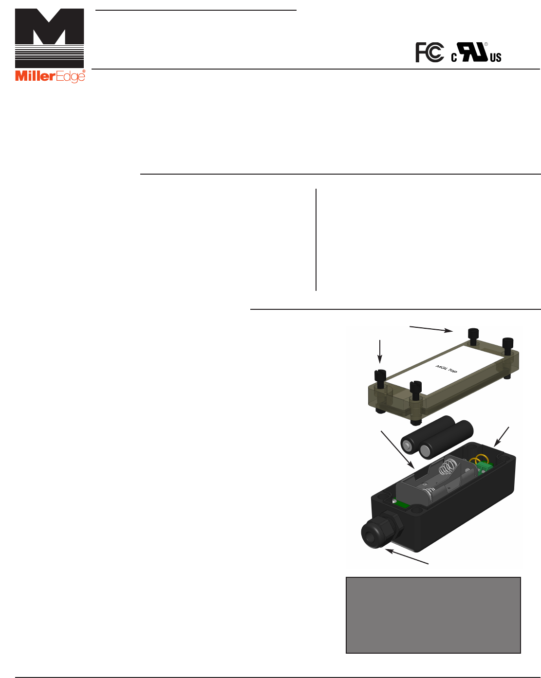
2-1. Open and unpack the antenna, batteries,
transmitter and receiver units.
2-2. Loosen screws from the top cover and
remove the lid.
2-3. Route the wires from the monitored edge
through the strain relief cable fitting for
approximately four inches.
Strip the insulation from the two wires back ¼”
and secure the wires in the terminal block
marked SE 1. (not polarized.)
2-4. Place the two AA lithium batteries in their holders
in the proper direction, paying attention to the (+)
and (-) ends.
2-5. Tuck the wires connected to the SE terminal
block neatly and pull the excess wire back
through the strain relief. Securely tighten the
cable fitting.
P.O. Box 159 • West Grove, PA 19390 • 800-220-3343 • 610-869-4422 • Fax: 610-869-4423 • www.milleredge.com
6809 South Harl Ave., Suite A • Tempe, AZ 85283 • 800-887-3343 • 480-755-3565 • Fax: 480-755-3558
MGL-K20_Inst_20151015
Model # MGL-K20
INSTALLATION INSTRUCTIONS
IMPORTANT:
READ AND UNDERSTAND ALL INSTRUCTIONS BEFORE BEGINNING INSTALLATION
Kit Contents:
1. MGL-TX20 Transmitter unit
2. MGL-RX20 Receiver unit
3. Receiver antenna
4. (2) AA lithium batteries
5. (4) #6 pan head transmitter mounting screws
1-Parts List
PART NUMBER
2-Install Transmitter and Test
The Monitored Gate Link (MGL) transmitter/receiver system is intended to provide a wireless connection between a monitored
safety edge and a motorized operator that controls the associated gate. MGL meets the UL 325-2016 requirements for
monitored devices and has been certified as a UL 325 recognized component. It is designed for use on operators that comply with
UL 325-2016 using a T2 terminated edge sensor.
Required:
1. 1/8” flat blade screwdriver
2. 1/4” flat blade screwdriver
3. T2 (10K/BLUE BAND) terminated sensing edge
Recommended:
• VOM for test purposes
• Mounting screws as required for receiver
(2-6) EDGE WIRING TO SEI
TERMINAL BLOCK
TOP LID
SCREWS
TEST BUTTON
TRANSMITTER
PCB
STRAIN RELIEF
FITTING
Monitored Gate Link
Image Pending
2-6. Momentarily press the “test” button. The green Tx data LED should flash.
2-7. Mount the Transmitter to the gate using #6 – 20 x 3/4” self-drilling screws. The mounting holes
are located under the top lid screws. Mount the transmitter with the wire strain relief facing down.
2-8. Replace the cover on the transmitter and tighten the screws taking care to align the lid.
*Note the alignment pin located in the upper left corner.
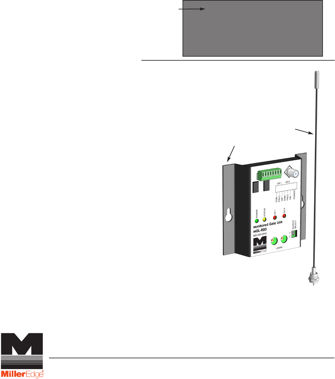
3-Install Receiver and Test
3-1. Mount the receiver inside the operator cover using
the pre-drilled mounting holes, as shown.
3-2. Attach the antenna to the receiver RF board. An
antenna extension cable may be required if the
operator chassis is metal.
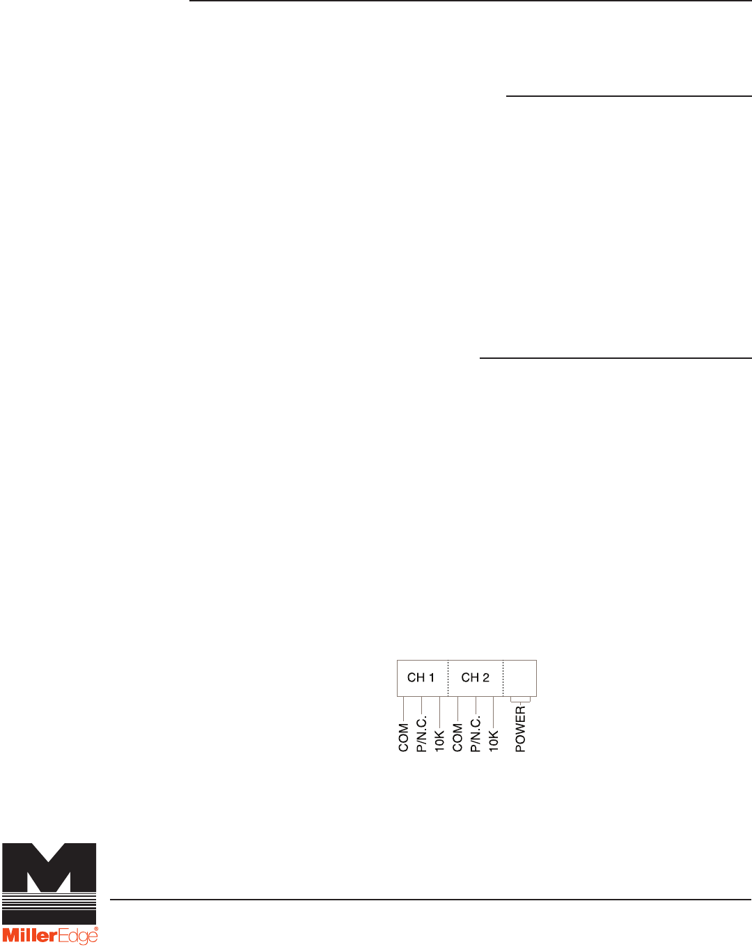
3-3. Connect your power source to the terminals
marked “power”. 12-24 VAC/DC. Your output
connections (COM and 10K or P/N.C.) will be
determined by your operator’s requirements.
The “output select” DIP switch will need to be
set accordingly: Switch 1 set to “P” for pulsed
output. Switch 1 set to “R” for N.C. (normally
closed) or 10KΩ resistor output. Switch 2 has
no function.
3-4. Confirm that the transmitter and receiver are
powered on.
3-5. Green power LED stays on; channel 2 red LED
will be blinking.
3-6. To enter “learn” mode, press CH1 (in the learn
section of the PCB). The red led remains
on and the amber status LED will blink.
3-7. Activate the transmitting edge and note the red and
amber LEDs will blink alternately rapidly. Then the
red LED will go out and the amber LED remains on.
3-8. Channel 1 is now programmed. Repeat for
Channel 2 (if desired).
3-9. To start over or erase programming, press and hold
both buttons for 3 seconds. The LEDs will
blink rapidly and then go into “fault” mode. Repeat
the programming steps above.
ANTENNA
MOUNTING
TABS (2)
RECEIVER
ENCLOSURE
(4) CORNER
MOUNTING HOLES
P.O. Box 159 • West Grove, PA 19390 • 800-220-3343 • 610-869-4422 • Fax: 610-869-4423 • www.milleredge.com
6809 South Harl Ave., Suite A • Tempe, AZ 85283 • 800-887-3343 • 480-755-3565 • Fax: 480-755-3558
Image Pending
Frequency: 916 MHz, FSK modulation
Indicator Lights—Tx: Green LED: Tx Data, Flashes upon activation and release of the
external safety device to indicate transmission
Mounting: 4 corner screws (provided)
Power Source: Batteries: 2 AA, 1.5v lithium* or alkaline
*Recommended for extended life in prolonged cold environments. Life expectancy: 2 years
Dimensions: 1.80”W x 4.78”H x 1.75”D
Test Button: Momentary push button—forces the transmission of the transmitter's address
and sensor status
5-Specifications and Controls: Transmitter Unit
6-Specifications and Controls: Receiver Unit
Power: 12-24 VAC/DC nominal (8-30V max); power may be supplied from the operator or
alternatively from an external supply
Cable Connections: Screw clamp type terminal blocks for 18-26 AWG wire
Learn Buttons: Used to associate a transmitter with the desired receiver channel
Output Selector: Select “P” for Pulsed, or “R” for Relay mode; switch 2 is not used
Dimensions: 4”W x 4.74”H x 1”D
Indicator Lights—Rx:
• Yellow LED blinks “off”; indicates reception of message with our selected address
If flashing: learn mode
• Red LED: indicates safety device is active
If flashing: rapid blinking indicates a termination fault; slow blinking indicates a
low battery condition on the associated transmitter
Connections:
Modes: Refer to your operator’s manual
• Pulsed (photo eye)
• N.C. (normally closed)
• 10KΩ resistor
4-Safety Test
4-1. While moving the gate in the desired direction, momentarily activate the Safety Edge and confirm
that the gate stops/reverses direction.
P.O. Box 159 • West Grove, PA 19390 • 800-220-3343 • 610-869-4422 • Fax: 610-869-4423 • www.milleredge.com
6809 South Harl Ave., Suite A • Tempe, AZ 85283 • 800-887-3343 • 480-755-3565 • Fax: 480-755-3558

Transmitter:
MODEL: MGL-TX20
FCC ID: OYE-MGL-916
THIS DEVICE COMPLIES WITH PART 15 OF THE FCC RULES. OPERATIONS IS SUBJECT TO THE
FOLLOWING TWO CONDITIONS:
1) THIS DEVICE MAY NOT CAUSE HARMFUL INTERFERENCE
AND
2) THIS DEVICE MUST ACCEPT ANY INTERFERENCE RECEIVED INCLUDING INTERFERENCE
THAT MAY CAUSE UNDESIRED OPERATION.
Receiver:
MODEL: MGL-RX20
This equipment has been tested and found to comply with the limits for a Class B digital device, pursuant to
Part15 of the FCC Rules.
These limits are designed to provide reasonable protection against harmful interference in a residential
installation. This equipment generates, uses and can radiate radio frequency energy and, if not installed and
used in accordance with the instructions, may cause harmful interference to radio communications. However,
there is no guarantee that interference will not occur in a particular installation. If this equipment does cause
harmful interference to radio or television reception, which may be determined by turning the equipment off
and on, the user is encouraged to try to correct the interference by one or more of the following measures:
1- Re-orient or relocate the receiver antenna
2- Increase the separation between the equipment and the receiver
3- Connect the equipment into an outlet on a circuit different from that to which the receiver is connected.
4- Consult the dealer or an experienced radio/TV technician for help.
Changes or Modifications Not Expressly Approved By The Party Responsible For Compliance Could Void
The User’s Authority To Operate The Equipment.
7-FCC Compliance
P.O. Box 159 • West Grove, PA 19390 • 800-220-3343 • 610-869-4422 • Fax: 610-869-4423 • www.milleredge.com
6809 South Harl Ave., Suite A • Tempe, AZ 85283 • 800-887-3343 • 480-755-3565 • Fax: 480-755-3558