Miller Edge MWCK02 Safety Device Transmitter / Receiver User Manual Communicator Inst 7 31 03 FINAL
Miller Edge, Inc. Safety Device Transmitter / Receiver Communicator Inst 7 31 03 FINAL
OPerational MAnual

The Communicator
Wireless Transmitter/Receiver
Installation Instructions
TO REDUCE RISK OF SEVERE INJURY OR DEATH;
READ AND FOLLOW ALL INSTALLATION INSTRUCTIONS
TO PREVENT ELECTROCUTION DISCONNECT POWER AT FUSE BOX OR CIRCUIT
BREAKER AND DOOR OPENER BEFORE WIRING PERMANENTLY.
IMPROPER WIRING COULD CAUSE ELECTROCUTION OR DAMAGE TO CIRCUITRY.
FOLLOW ALL LOCAL BUILDING CODES AND NATIONAL ELECTRICAL CODES.
WARNING!
TRANSMITTER INSTALLATION:
1- Remove lid from top of the MWCT-01 Transmitter to reveal mounting holes. Position the Transmitter near
the bottom of the door and mark the mounting hole locations.
2. Remove the Transmitter from door, drill holes and mount the Transmitter with screws supplied.
3- Loosen wire fitting nut and feed the 4-wire sensing edge leads into the Transmitter housing trimming off excess wire.
4- Attach the 4-lead wires to the large green two-part terminal block connector as White White, Black Black.
Tighten the wire fitting nut to assure water tight connection.
5- Adjust Dip Switches: 1= Channel Selector 2= Channel Selector 3= NOT USED
4= Address Selector 5= Address Selector
(SEE FIGURE 1 FOR SWITCH CONFIGURATIONS.)
5- Be sure that the battery strap is connected and insert 9 Volt battery into the lid of the unit, and replace the lid.
The Green LED light should light up indicating that the unit is functioning properly.
RECEIVER INSTALLATION:
1- Hold the MWCR-01 Receiver up near the operator, mark and drill mounting holes.
2- Attach a 24VAC (at least 200mA) source to the red & black wires. A 12-28 VDC source may also be used.
Polarity does not matter here.
3- Connect channel 1 to the white wires, channel 2 (if present) to the yellow wires, channel 3 to orange wires.
The output relays will bear a load of 1A at 24VAC and 0.5A at 110VAC. Each channel has an associated
YELLOW LED. The LED is illuminated when the channel is in a SAFE operating condition and will go out
under fault condition.
4- There is a GREEN LED located near the dip switches which indicates SIGNAL ACQUIRED. It should turn on within
a ew seconds of the transmitter contacting the receiver.
5- There is also a RED LED located in the same place, which signals MAINTENANCE REQUIRED. It will illuminate
when there is a condition such as low battery or tampering.
MILLER EDGE, INC. • P.O. Box 159 • West Grove, PA 19390 • 610-869-4422 • Fax: 610-869-4423 • 1-800-220-EDGE • www.milleredge.com
MILLER EDGE, INC. • 6809 South Harl Avenue • Suite A • Tempe, AZ 85283 • 480-755-3565 • Fax: 480-755-3558 • 1-800-887-EDGE
REV. 7-31-03
ON 5
4
3
21
RECEIVER INSTALLATION Cont.
6- Adjust Dip Switches: 1=Mode Selector 2= Mode Selector 3= NOT USED
4= Address Selector 5= Address Selector
(SEE FIGURE 1 FOR SWITCH CONFIGURATIONS.)
Modes are as follows:
Switch 1 down, Switch 2 down: Mode Selected for Signal from one (1) Transmitter
Switch 1 up, Switch 2 down: Mode Selected for Signal from two (2) Transmitters
Switch 1 up, Switch 2 up: Mode Selected for Signal from two (3) Transmitters
7- Mount the Receiver near the operator using the 2 screws supplied.
8- Attach Coax Rigid Wire antenna.
9- Test door/gate operation to see that the system is functioning properly.
OFF(0)
ON 5
4
3
21
OFF(0)
ON 5
4
3
21
OFF(0)
ON 5
4
3
21
OFF(0)
ON 5
4
3
21
OFF(0)
ON 5
4
3
21
OFF(0)
ON 5
4
3
21
OFF(0)
ON 5
4
3
21
OFF(0)
ON 5
4
3
21
OFF(0)
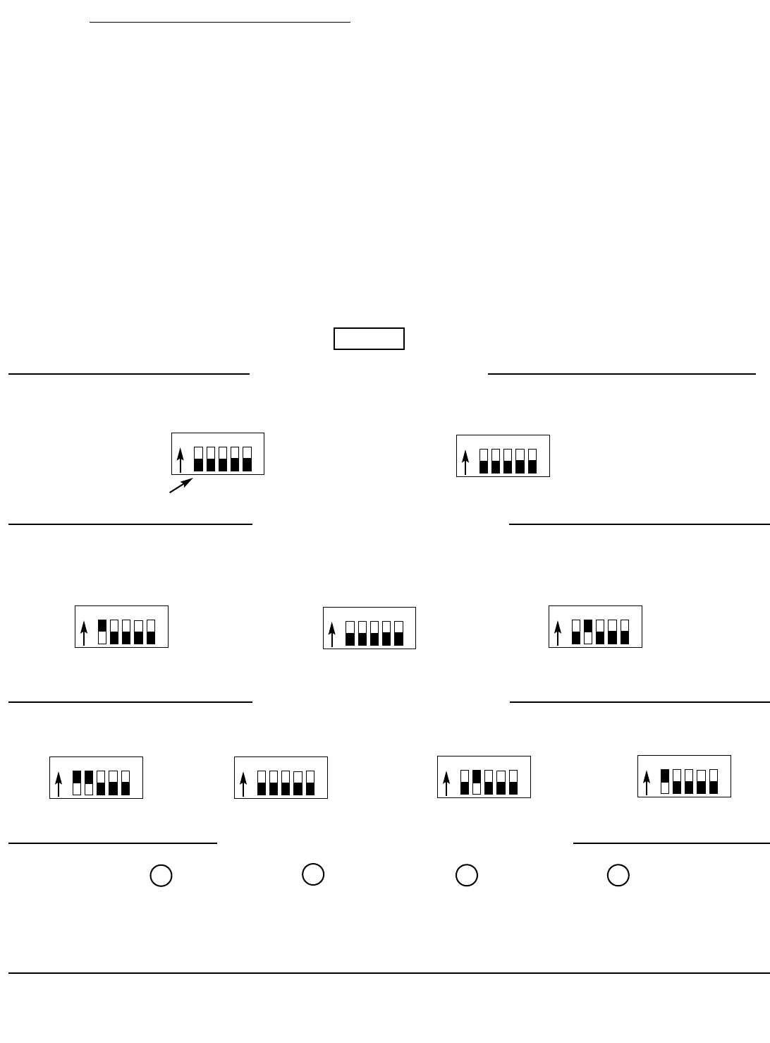
RECEIVER SWITCH SETTING TRANSMITTER SWITCH SETTING
1 RECEIVER W/ 1 TRANSMITTER
1 RECEIVER W/ 2 TRANSMITTERS
RECEIVER SWITCH SETTING TRANSMITTER #1
SWITCH SETTINGS TRANSMITTER #2
SWITCH SETTINGS
1 RECEIVER W/ 3 TRANSMITTERS
LED DIAGNOSTICS (Inside Receiver Enclosure)
SWITCH SHOWN IN
DOWN (OFF) POSITION
RECEIVER SWITCH SETTING TRANSMITTER #1
SWITCH SETTINGS
TRANSMITTER #2
SWITCH SETTINGS TRANSMITTER #3
SWITCH SETTINGS
FIGURE 1
POWER
(Green) CHANNEL 1
RELAY CHANNEL 2
RELAY
CHANNEL 3
RELAY
NOTE: RELAY LIGHTS ARE YELLOW
MILLER EDGE, INC. • P.O. Box 159 • West Grove, PA 19390 • 610-869-4422 • Fax: 610-869-4423 • 1-800-220-EDGE • www.milleredge.com
MILLER EDGE, INC. • 6809 South Harl Avenue • Suite A • Tempe, AZ 85283 • 480-755-3565 • Fax: 480-755-3558 • 1-800-887-EDGE