Miller Electric Aead 200 Le Users Manual CD1
AEAD-200-LE 76a0fd45-4c0c-4d62-84fd-51cac434075a
2015-02-02
: Miller-Electric Miller-Electric-Aead-200-Le-Users-Manual-437163 miller-electric-aead-200-le-users-manual-437163 miller-electric pdf
Open the PDF directly: View PDF ![]() .
.
Page Count: 68
- TABLE OF CONTENTS
- 1 - SAFETY PRECAUTIONS FOR SERVICING
- 2 - INSTALLATION
- 3 - OPERATING WELDING GENERATOR
- 4 - OPERATING AUXILIARY EQUIPMENT
- 5 - THEORY OF OPERATION
- 6 - TROUBLESHOOTING
- 6-1. Troubleshooting Tables
- 6-2. Troubleshooting Circuit Diagram For Welding Generator
- 6-3. Troubleshooting Circuit Diagram For Welding Generator With Optional Remote Control
- 6-4. Waveforms For Sections 6-2 And 6-3
- 6-5. Idle Control Board/Module PC1 Testing Information
- 6-6. Troubleshooting Flowcharts For Idle Control Board/Module PC1
- 6-7. Voltage Regulator Board PC2 Testing Information Prior To Serial No. KE604176
- 6-8. Voltage Regulator Board PC2 Test Point Values Prior To Serial No. KE604176
- 6-9. Voltage Regulator Board PC2 Testing Information Effective With Serial No. KE604176
- 6-10. Voltage Regulator Board PC2 Test Point Values Effective With Serial No. KE604176
- 6-11. Optional Remote Control Board PC3 Testing Information
- 6-12. Optional Remote Control Board PC3 Test Point Values
- 6-13. Optional Remote Capacitor Board PC5 Testing Information Effective With Serial No. KD346698
- 6-14. Optional Remote Capacitor Board PC5 Test Point Values Effective With Serial No. KD346698
- 6-15. Replacing Brushes And Cleaning Slip Rings
- 6-16. Checking Unit Output After Servicing
- 7 - DISASSEMBLY AND REASSEMBLY
- 8 - MAINTENANCE
- 9 - ELECTRICAL DIAGRAMS
- 10 - PARTS LIST
February 1996 Form: TM-428
Effective With Serial No. JH242114
TECHNICAL MANUAL
Service And Parts
cover_tm 4/95 – ST-140 091-E PRINTED IN USA
1996 MILLER Electric Mfg. Co.
Miller Legend
(Formerly The Legend AEAD-200LE)
CC AC/DC Welding Generator For SMAW, GMAW, GTAW Welding
Welding
Mode
Weld
Output
Range
Rated
Welding
Output
Maximum
Open-Circu
it Voltage
Auxiliary Power
Rating Fuel Capacity Engine
CC/AC 35
– 225 A
225 A, 25 V
,
100% Duty
Cycle 80 Single-Phase,
5 kVA/kW
, 42/21 A,
120/240 V AC, 60 Hz
And
7 5 gal (28 L) T
ank
Onan P218 Air-Cooled,
Two
-
Cylinder, Four
-
Cycle,
CC/DC
25 – 200 A
200 A, 25 V
,
100% Duty
Cycle 72
And
Single-Phase,
1 kVA/kW
, 9 A,
1
15 V AC, 100 Hz
7.5 gal (28 L) T
ank
T
wo-
C
y
li
n
d
er,
F
our-
C
yc
l
e,
Gasoline Engine

OM-428N 1/96 – SPM-428C 6/94
HCALL:
Miller Customer Service
Department at
414-735-4505
WHO DO I CONTACT FOR HELP?
HFAX:
800-637-2348
(in USA),
or
414-735-4136 (outside USA)
HWRITE:
Miller Electric Mfg. Co.
P
.O. Box 1079
Appleton, WI 54912 USA
Always provide Model Name and Serial or Style Number
TABLE OF CONTENTS
SECTION 1 – SAFETY PRECAUTIONS FOR SERVICING 1.
. . . . . . . . . . . . . . . . . . . . . . . . . . . . . . . . . . .
1-1. Symbol Usage 1.
. . . . . . . . . . . . . . . . . . . . . . . . . . . . . . . . . . . . . . . . . . . . . . . . . . . . . . . . . . . . . . . .
1-2. Servicing Hazards 1.
. . . . . . . . . . . . . . . . . . . . . . . . . . . . . . . . . . . . . . . . . . . . . . . . . . . . . . . . . . . . .
1-3. EMF Information 2.
. . . . . . . . . . . . . . . . . . . . . . . . . . . . . . . . . . . . . . . . . . . . . . . . . . . . . . . . . . . . . .
SECTION 2 – INSTALLATION 3.
. . . . . . . . . . . . . . . . . . . . . . . . . . . . . . . . . . . . . . . . . . . . . . . . . . . . . . . . . . . .
2-1. Installing
W
elding Generator 3.
. . . . . . . . . . . . . . . . . . . . . . . . . . . . . . . . . . . . . . . . . . . . . . . . . . . .
2-2. Dimensions,
W
eights, And Operating Angles 3.
. . . . . . . . . . . . . . . . . . . . . . . . . . . . . . . . . . . . . .
2-3. Fuel Consumption 4.
. . . . . . . . . . . . . . . . . . . . . . . . . . . . . . . . . . . . . . . . . . . . . . . . . . . . . . . . . . . . .
2-4. Engine Prestart Checks 4.
. . . . . . . . . . . . . . . . . . . . . . . . . . . . . . . . . . . . . . . . . . . . . . . . . . . . . . . .
2-5. Connecting The Battery 5.
. . . . . . . . . . . . . . . . . . . . . . . . . . . . . . . . . . . . . . . . . . . . . . . . . . . . . . . .
2-6. Connecting To Weld Output Terminals 5.
. . . . . . . . . . . . . . . . . . . . . . . . . . . . . . . . . . . . . . . . . . . .
2-7. Selecting
W
eld Cable Sizes 6.
. . . . . . . . . . . . . . . . . . . . . . . . . . . . . . . . . . . . . . . . . . . . . . . . . . . . .
2-8. Remote 14 Receptacle RC1 Information 6.
. . . . . . . . . . . . . . . . . . . . . . . . . . . . . . . . . . . . . . . . . .
SECTION
3 – OPERA
TING WELDING GENERATOR 7.
. . . . . . . . . . . . . . . . . . . . . . . . . . . . . . . . . . . . . . . .
3-1. Front Panel Controls 7.
. . . . . . . . . . . . . . . . . . . . . . . . . . . . . . . . . . . . . . . . . . . . . . . . . . . . . . . . . . .
3-2. Remote Control (Optional) 8.
. . . . . . . . . . . . . . . . . . . . . . . . . . . . . . . . . . . . . . . . . . . . . . . . . . . . . .
3-3. Duty Cycle 8.
. . . . . . . . . . . . . . . . . . . . . . . . . . . . . . . . . . . . . . . . . . . . . . . . . . . . . . . . . . . . . . . . . . . .
3-4. Volt-Ampere Curves 9.
. . . . . . . . . . . . . . . . . . . . . . . . . . . . . . . . . . . . . . . . . . . . . . . . . . . . . . . . . . .
SECTION
4 – OPERA
TING AUXILIAR
Y EQUIPMENT
10.
. . . . . . . . . . . . . . . . . . . . . . . . . . . . . . . . . . . . . . .
4-1. 100 Hz Auxiliary Power Receptacle And Circuit Breaker 10.
. . . . . . . . . . . . . . . . . . . . . . . . . . . .
4-2. AC Auxiliary Power Curve 10.
. . . . . . . . . . . . . . . . . . . . . . . . . . . . . . . . . . . . . . . . . . . . . . . . . . . . . .
4-3. 60 Hz Auxiliary Power Receptacles And Circuit Breakers 11.
. . . . . . . . . . . . . . . . . . . . . . . . . . .
SECTION 5 – THEOR
Y OF OPERA
TION 12.
. . . . . . . . . . . . . . . . . . . . . . . . . . . . . . . . . . . . . . . . . . . . . . . . . . .
SECTION 6 – TROUBLESHOOTING 15.
. . . . . . . . . . . . . . . . . . . . . . . . . . . . . . . . . . . . . . . . . . . . . . . . . . . . . .
6-1. Troubleshooting Tables 15.
. . . . . . . . . . . . . . . . . . . . . . . . . . . . . . . . . . . . . . . . . . . . . . . . . . . . . . . . .
6-2. Troubleshooting Circuit Diagram For Welding Generator 18.
. . . . . . . . . . . . . . . . . . . . . . . . . . . .
6-3. Troubleshooting Circuit Diagram For Welding Generator With Optional Remote Control 20.
.
6-4. Waveforms For Sections 6-2 And 6-3 22.
. . . . . . . . . . . . . . . . . . . . . . . . . . . . . . . . . . . . . . . . . . . .
6-5. Idle Control Board/Module PC1 Testing Information 23.
. . . . . . . . . . . . . . . . . . . . . . . . . . . . . . . .
6-6. Troubleshooting Flowcharts For Idle Control Board/Module PC1 24.
. . . . . . . . . . . . . . . . . . . . .
6-7. Voltage Regulator Board PC2 Testing Information Prior To Serial No. KE604176 26.
. . . . . . .
6-8. Voltage Regulator Board PC2 Test Point Values Prior To Serial No. KE604176 26.
. . . . . . . .
6-9. Voltage Regulator Board PC2 Testing Information Effective With Serial No. KE604176 27.
. .
6-10. Voltage Regulator Board PC2 Test Point Values Effective With Serial No. KE604176 27.
. . .
6-11. Optional Remote Control Board PC3 Testing Information 28.
. . . . . . . . . . . . . . . . . . . . . . . . . . .
6-12. Optional Remote Control Board PC3 Test Point Values 28.
. . . . . . . . . . . . . . . . . . . . . . . . . . . . .
6-13. Optional Remote Capacitor Board PC5 Testing Information Effective With
Serial No. KD346698 29.
. . . . . . . . . . . . . . . . . . . . . . . . . . . . . . . . . . . . . . . . . . . . . . . . . . . . . . . . . .
6-14. Optional Remote Capacitor Board PC5 Test Point Values Effective With
Serial No. KD346698 29.
. . . . . . . . . . . . . . . . . . . . . . . . . . . . . . . . . . . . . . . . . . . . . . . . . . . . . . . . . .
6-15. Replacing Brushes And Cleaning Slip Rings 30.
. . . . . . . . . . . . . . . . . . . . . . . . . . . . . . . . . . . . . .
6-16. Checking Unit Output After Servicing 32.
. . . . . . . . . . . . . . . . . . . . . . . . . . . . . . . . . . . . . . . . . . . . .
SECTION 7 – DISASSEMBL
Y AND REASSEMBL
Y33.
. . . . . . . . . . . . . . . . . . . . . . . . . . . . . . . . . . . . . . . . .
7-1. Disassembly Of Unit 33.
. . . . . . . . . . . . . . . . . . . . . . . . . . . . . . . . . . . . . . . . . . . . . . . . . . . . . . . . . . .
7-2. Disassembly Of Generator 34.
. . . . . . . . . . . . . . . . . . . . . . . . . . . . . . . . . . . . . . . . . . . . . . . . . . . . . .
SECTION 8 – MAINTENANCE 35.
. . . . . . . . . . . . . . . . . . . . . . . . . . . . . . . . . . . . . . . . . . . . . . . . . . . . . . . . . . . .
8-1. Routine Maintenance 35.
. . . . . . . . . . . . . . . . . . . . . . . . . . . . . . . . . . . . . . . . . . . . . . . . . . . . . . . . . .
8-2. Maintenance Label 36.
. . . . . . . . . . . . . . . . . . . . . . . . . . . . . . . . . . . . . . . . . . . . . . . . . . . . . . . . . . . .
8-3. Servicing Air Cleaner 37.
. . . . . . . . . . . . . . . . . . . . . . . . . . . . . . . . . . . . . . . . . . . . . . . . . . . . . . . . . .
8-4. Changing Engine Oil, Oil Filter, And Fuel Filter 38.
. . . . . . . . . . . . . . . . . . . . . . . . . . . . . . . . . . . .
8-5. Adjusting Engine Speed 39.
. . . . . . . . . . . . . . . . . . . . . . . . . . . . . . . . . . . . . . . . . . . . . . . . . . . . . . . .
8-6. Overload Protection 40.
. . . . . . . . . . . . . . . . . . . . . . . . . . . . . . . . . . . . . . . . . . . . . . . . . . . . . . . . . . . .
8-7. Inspecting And Cleaning Optional Spark Arrestor 40.
. . . . . . . . . . . . . . . . . . . . . . . . . . . . . . . . . .
SECTION 9 – ELECTRICAL DIAGRAMS 41.
. . . . . . . . . . . . . . . . . . . . . . . . . . . . . . . . . . . . . . . . . . . . . . . . . .
SECTION 10 – PARTS LIST 51.
. . . . . . . . . . . . . . . . . . . . . . . . . . . . . . . . . . . . . . . . . . . . . . . . . . . . . . . . . . . . . .

TM-428 Page 1
Miller Legend
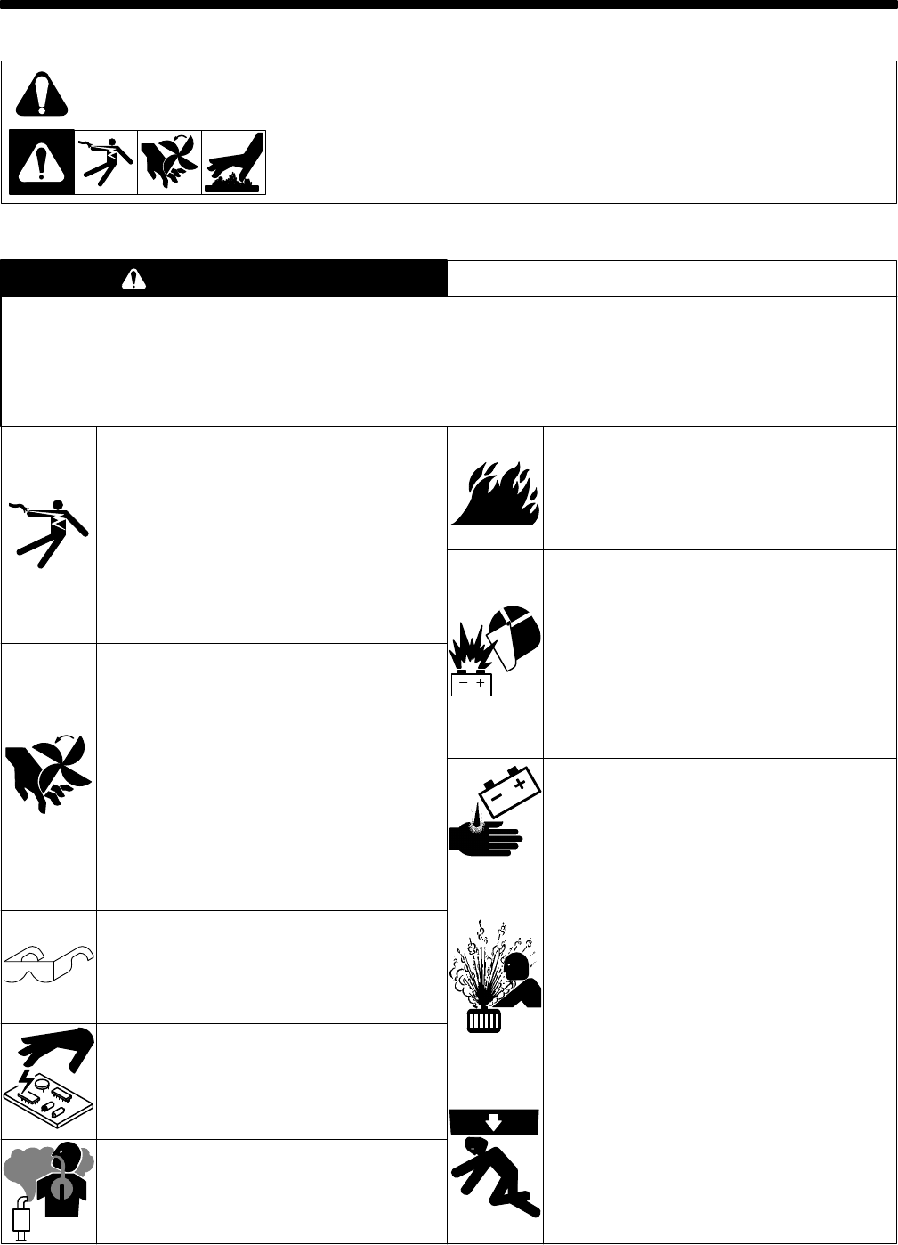
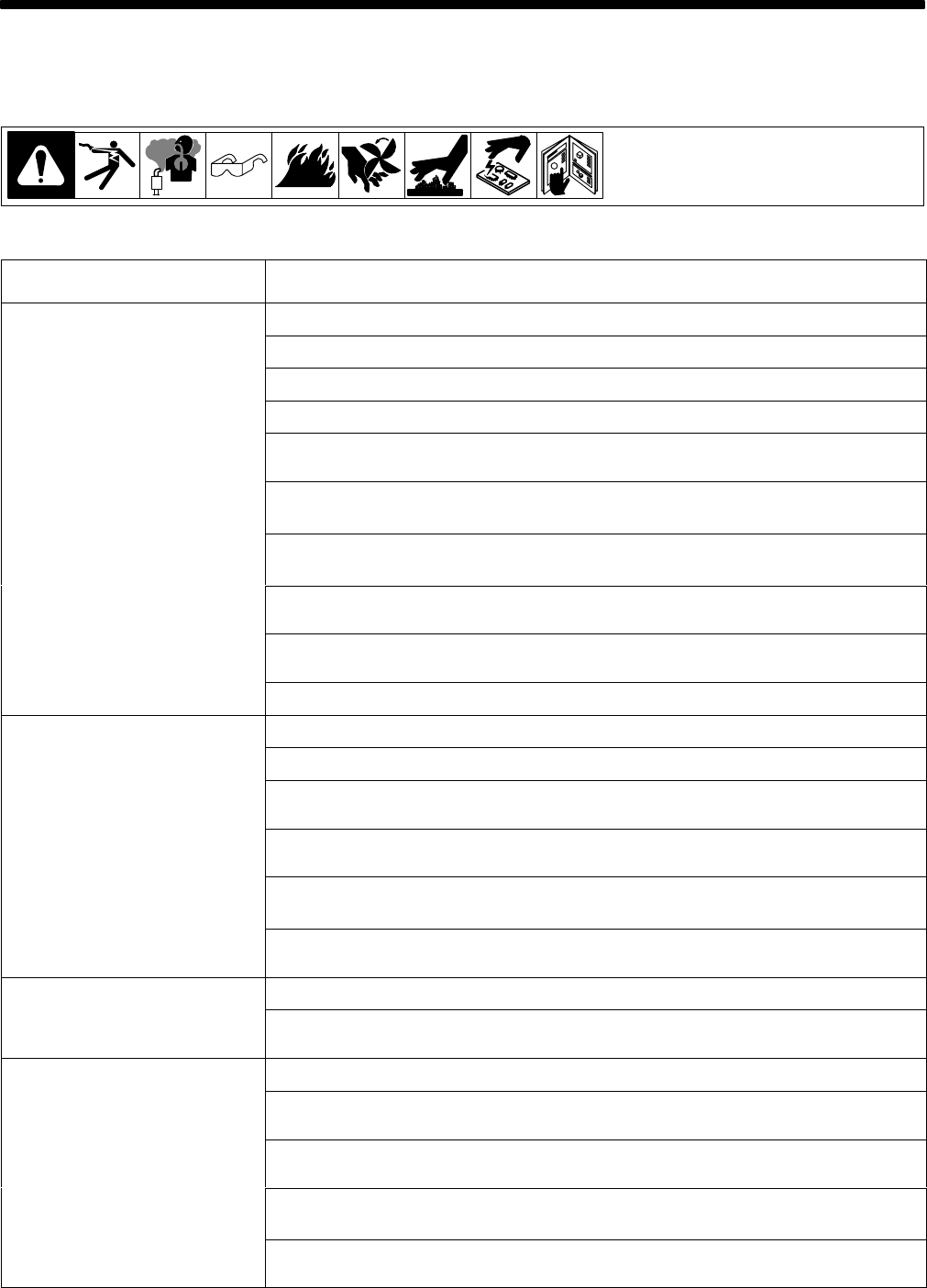
SECTION 1 – SAFETY PRECAUTIONS FOR SERVICING
safety_rtm1 4/95
1-1. Symbol Usage
Means Warning! Watch Out! There are possible hazards with this
procedure!
The possible hazards are shown in the adjoining symbols.
This group of symbols means Warning! Watch Out! possible ELECTRIC SHOCK, MOVING
PARTS,
and HOT P
AR
TS hazards. Consult symbols and related instructions below for necessary
actions
to avoid the hazards.
Y
Marks a special safety message.
.
Means NOTE; not safety related.
1-2. Servicing Hazards
ELECTRIC SHOCK can kill.
1. Do
not touch live electrical parts.
2. Stop
engine before testing or repairing unit unless
the procedure specifically requires an energized
unit.
3. Insulate yourself from ground by standing or
working on dry insulating mats big enough to
prevent
contact with the ground.
4.
Do not leave live unit unattended.
5. When
testing live unit, use
the one-hand method.
Do not put both hand inside unit. Keep one
hand
free.
MOVING
P
ARTS can cause injury.
1. Keep
away from moving
parts such as fans, belts,
and
rotors.
2. Have only qualified people remove guards or
covers for maintenance and troubleshooting as
necessary.
3. Keep hands, hair, loose clothing, and tools away
from
moving parts.
4. Before
working on generator
, remove spark plugs
or injectors to keep engine from kicking back or
starting.
5. Block
flywheel so that it will not
turn while working
on
generator components.
6.
Reinstall panels or
guards and close doors when
servicing is finished and before starting engine.
FLYING
PIECES
OF MET
AL or DIRT can
cause injury.
1. Always wear safety glasses with side shields or
face
shield during servicing.
2. Be
careful not to short metal tools, parts, or wires
together
during testing and servicing.
STATIC
ELECTRICITY
can damage parts
on circuit boards.
1. Put on grounded wrist strap BEFORE handling
boards
or parts.
2. Use proper static-proof bags to store, move, or
ship
PC boards.
ENGINE EXHAUST GASES can kill.
1. Do
not breathe exhaust fumes.
2. Use in open, well-ventilated areas, or vent
exhaust outside and away from any building air
intakes.
ENGINE FUEL can cause fire or
explosion.
1. Stop
engine before fueling.
2. Do not fuel while smoking or near sparks or
flames.
3. Do
not overfill tank; clean up any spilled fuel.
BATTERY EXPLOSION can BLIND and
INJURE.
1. Always wear a face shield when working on a
battery.
2. Stop engine before disconnecting or connecting
battery
cables.
3. Do
not allow tools to cause sparks when working
on a battery
.
4. Do
not use welder to charge batteries or jump
start
vehicles.
5. Observe
correct polarity (+ and –) on batteries.
BATTERY ACID can BURN SKIN.
1. Do
not tip.
2.
Replace damaged battery
.
3.
Flush eyes and skin immediately with water
.
STEAM AND PRESSURIZED HOT
COOLANT can burn face, eyes, and
skin.
1. Check coolant level when
engine is cold to avoid
scalding.
2. If the engine is warm and checking is needed,
follow
steps 3 and 4.
3. Wear
safety glasses and gloves and put a rag over
cap.
4. Turn cap slightly and let pressure escape slowly
before
completely removing cap.
FALLING EQUIPMENT can cause
serious personal injury and equipment
damage.
1. Use equipment of adequate capacity to lift
components.
2. Use
a lifting eye to lift unit only
,
NOT running gear
,
gas cylinders, or any other accessories.
3.
Securely attach components to lifting
equipment.
The symbols shown below are used throughout this manual to call attention to and identify possible
hazards. When you see the symbol, watch out, and follow the related instructions to avoid the hazard.
Only qualified persons should service, test, maintain, and repair this unit.
During servicing, keep everybody, especially children, away.
WARNING
TM-428 Page 2
Miller Legend
HOT PARTS can cause severe burns.
1. Allow
cooling period before servicing.
2. Wear
protective gloves and clothing when working
on
a hot engine.
ELECTRIC SHOCK HAZARD from
incorrect use of test equipment.
1. Stop engine before making or changing meter
lead
connections.
2. At
least one meter lead should be a self-retaining
spring
clip such as an alligator clamp.
3.
Read instructions for test equipment.
MAGNETIC FIELDS FROM HIGH
CURRENTS can affect pacemaker
operation.
1. Pacemaker wearers keep away from servicing
areas
until consulting your doctor
.
UNCONTROLLED TILTING OR TIPPING
OF UNIT can result in personal injury
and equipment damage.
1. Do
not put any body part under unit while lifting.
2. Use adequate blocks to support components as
needed
during job.
PINCH POINTS can injure.
1. Be careful when working on stator and rotor
assemblies.
HIGH-FREQUENCY RADIATION can
interfere with radio navigation, safety
services, computers, and
communications equipment.
1. Have only qualified persons familiar with
electronic
equipment perform this installation.
2. The user is responsible for having a qualified
electrician promptly correct any interference
problem
resulting from the installation.
3. If notified by the FCC about interference, stop
using
the equipment at once.
4. Have the installation regularly checked and
maintained.
5. Keep high-frequency source doors and panels
tightly shut, keep spark gaps at correct setting,
and use grounding and shielding to minimize the
possibility
of interference.
READ INSTRUCTIONS.
1. Use MILLER Testing Booklet (Part No. 150 853)
when
servicing this unit.
2. Consult the Owner’s Manual for welding safety
precautions.
3. Use
only genuine MILLER replacement parts.
4. Reinstall injectors and bleed air from fuel system
according to engine manual.
1-3. EMF Information
Considerations
About W
elding And The Ef
fects Of Low
Frequency
Electric
And Magnetic Fields
The
following is a quotation from the
General Conclusions Section
of
the U.S. Congress, Of
fice of T
echnology Assessment,
Biological
Effects of Power Frequency Electric & Magnetic Fields –
Background Paper
, OTA-BP-E-53 (Washington, DC: U.S.
Government Printing Office, May 1989): “. . . there is now a very
large volume of scientific findings based on experiments at the
cellular
level and from studies with
animals and people which clearly
establish that low frequency magnetic fields can interact with, and
produce
changes in, biological systems.
While most of this work is of
very high quality, the results are complex. Current scientific
understanding does not yet allow us to interpret the evidence in a
single coherent framework. Even more frustrating, it does not yet
allow us to draw definite conclusions about questions of possible
risk
or to of
fer clear science-based advice on strategies to minimize
or
avoid potential risks.”
To reduce magnetic fields in the workplace, use the following
procedures:
1. Keep
cables close together by twisting or taping them.
2.
Arrange cables to one side and away from the operator
.
3.
Do not coil or drape cables around the body
.
4.
Keep welding power source and cables as far away as
practical.
5.
Connect work clamp to workpiece as close to the weld as
possible.
About Pacemakers:
The above procedures are also recommended for pacemaker
wearers.
Consult your doctor for complete information.
TM-428 Page 3
Miller Legend
SECTION 2 – INSTALLATION
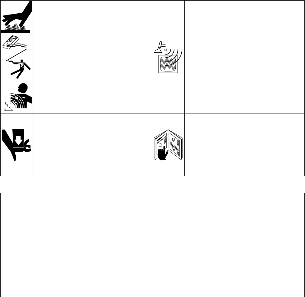
2-1. Installing Welding Generator
install1 10/95 – Ref. ST-800 652 / Ref. ST-800 477-A / ST-158 936-A / S-0854
1
2
Electrically
bond
generator frame to
vehicle frame by metal-to-metal
contact.
GND/PE
34
1 Generator Base
2
Metal V
ehicle Frame
3
Equipment Grounding
Terminal
4
Grounding Cable
Use #10 AWG or larger insulated
copper
wire.
YIf unit does not have GFCI
receptacles, use GFCI-pro-
tected
extension cord.
2
OR
18 in
(460 mm)
18 in
(460 mm)
18 in
(460 mm)
18 in
(460 mm)
18 in
(460 mm)
OR
Movement Airflow Location
Grounding
OR
YDo Not Lift Unit From End
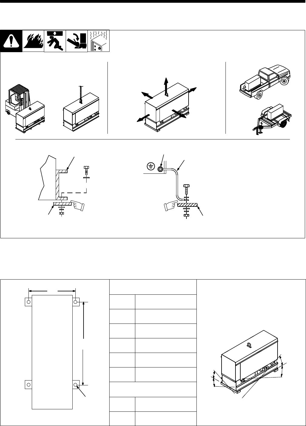
2-2. Dimensions, Weights, And Operating Angles
ADimensions
A
Height 31-5/8
in (803 mm)
YDo not exceed operating angles while
running
or engine damage will occur
.
D
t t it h it ld
Width 18
in (457 mm)
YDo
not move or operate unit where it could
tip.
Depth 45
in (1
143 mm)
BA 16-1/2
in (419 mm)
B 32-3/4
in (832 mm)
25°
C 13/16
in (21 mm) Dia.
25°
25
°
25°
Weight
25°
CNet 559
lb (254 kg)
Engine End
Ship 600
lb (272 kg)
TM-428 Page 4
Miller Legend
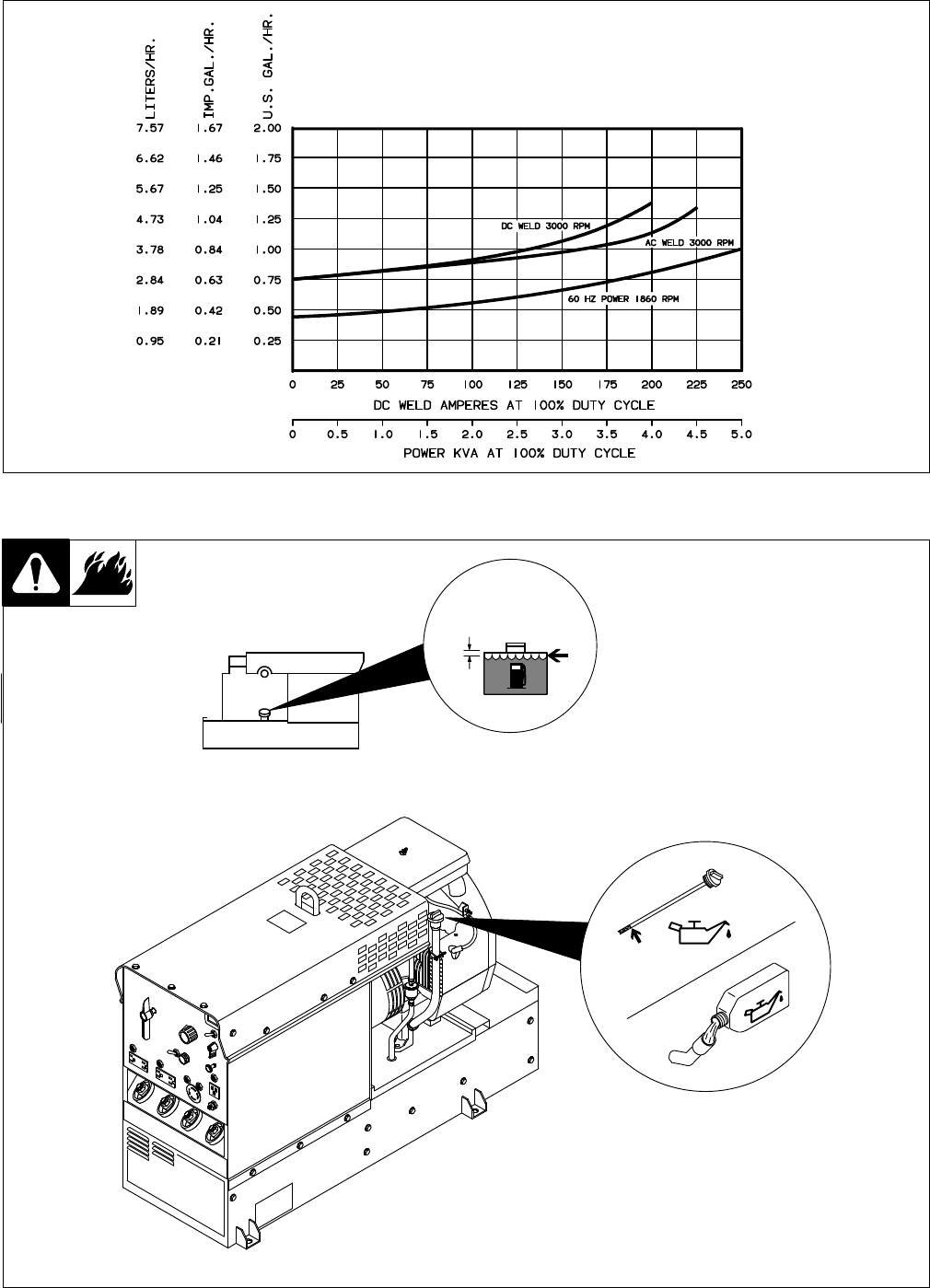
2-3. Fuel Consumption
SB-115 572
2-4. Engine Prestart Checks
ST-140 091-E / Ref. ST-151 983
Check
all fluids daily
. Engine must
be
cold and on a level surface.
Engine stops if oil pressure gets
too
low
.
1/2 in
(13 mm)
Full
Full
TM-428 Page 5
Miller Legend
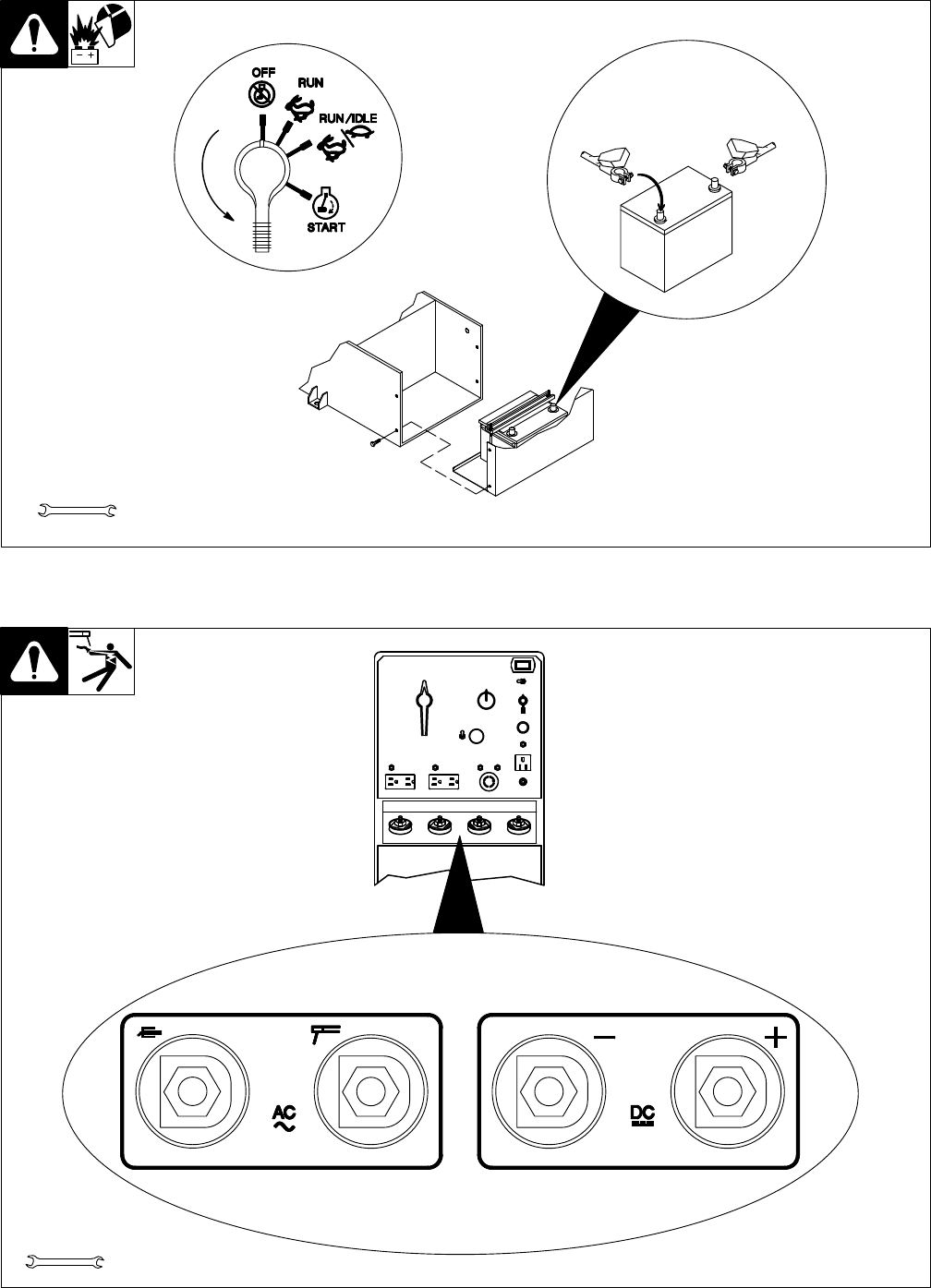
2-5. Connecting The Battery
Tools
Needed:
+–
3/8, 1/2 in
Y
Connect (–) cable last.
Ref. ST-144 839-F / Ref. ST-168 046 / Ref. S-0756-D
2-6. Connecting To Weld Output Terminals
YUse ONLY one set of termi-
nals at a time. Disconnect
weld
cables from
set of weld
output
terminals not in use.
ST-140 092-B / Ref. ST-168 046
Tools
Needed:
3/4 in
TM-428 Page 6
Miller Legend
2-7. Selecting Weld Cable Sizes
Total Cable (Copper) Length In Weld Circuit Not Exceeding
100 ft (30 m) Or Less 150 ft
(45 m) 200 ft
(60 m) 250 ft
(70 m) 300 ft
(90 m) 350 ft
(105 m) 400 ft
(120 m)
Welding
Amperes
10 – 60%
Duty Cycle
60 – 100%
Duty Cycle 10 – 100% Duty Cycle
100 4 4 4 3 2 1 1/0 1/0
150 3 3 2 1 1/0 2/0 3/0 3/0
200 3 2 1 1/0 2/0 3/0 4/0 4/0
250 2 1 1/0 2/0 3/0 4/0 2-2/0 2-2/0
300 1 1/0 2/0 3/0 4/0 2-2/0 2-3/0 2-3/0
350 1/0 2/0 3/0 4/0 2-2/0 2-3/0 2-3/0 2-4/0
Weld cable size (A
WG) is based on either a 4 volts or less drop or a current density of at least 300 circular mils per ampere.
S-0007-D
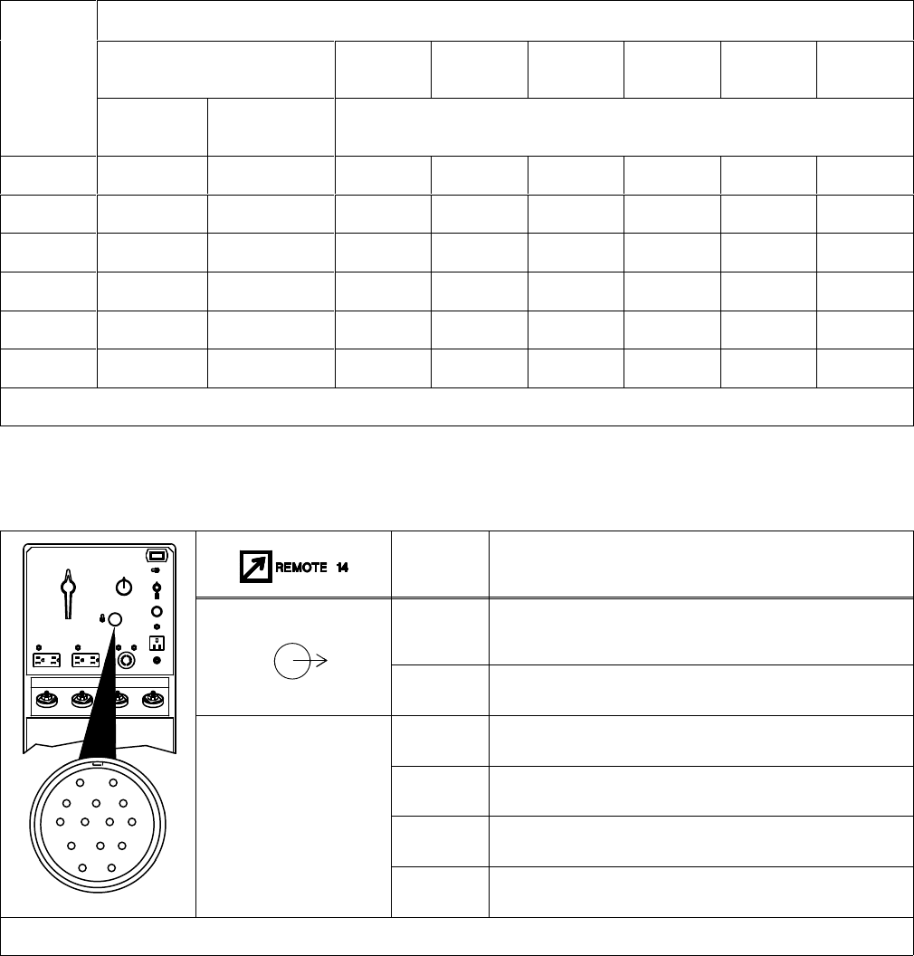
2-8. Remote 14 Receptacle RC1 Information
Socket* Socket Information
A Contact
closure to B completes 15 volts dc contactor control
circuit.
B 15 volts dc.
C +4.5
volts dc output to remote control.
AJ
B
K
I
A
DRemote
control circuit common.
B
CLNH
D
MG
E
F
A
E 0
to +4.5 volts dc input command signal from remote control.
ST-140 092-B
EFK Chassis
common.
*The remaining sockets are not used.
TM-428 Page 7
Miller Legend
SECTION 3 – OPERATING WELDING GENERATOR
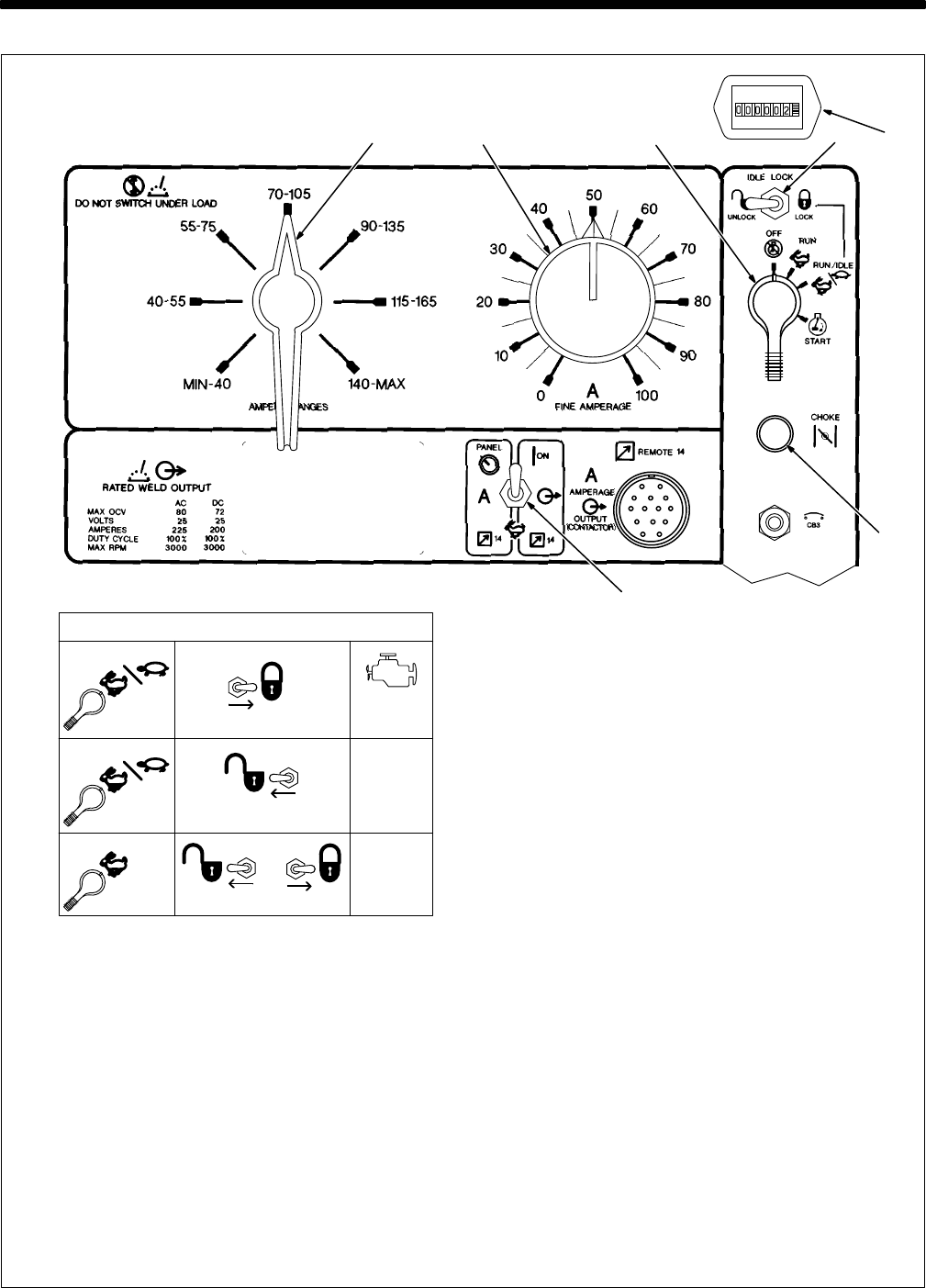
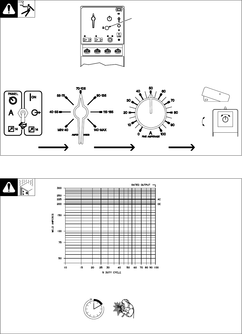
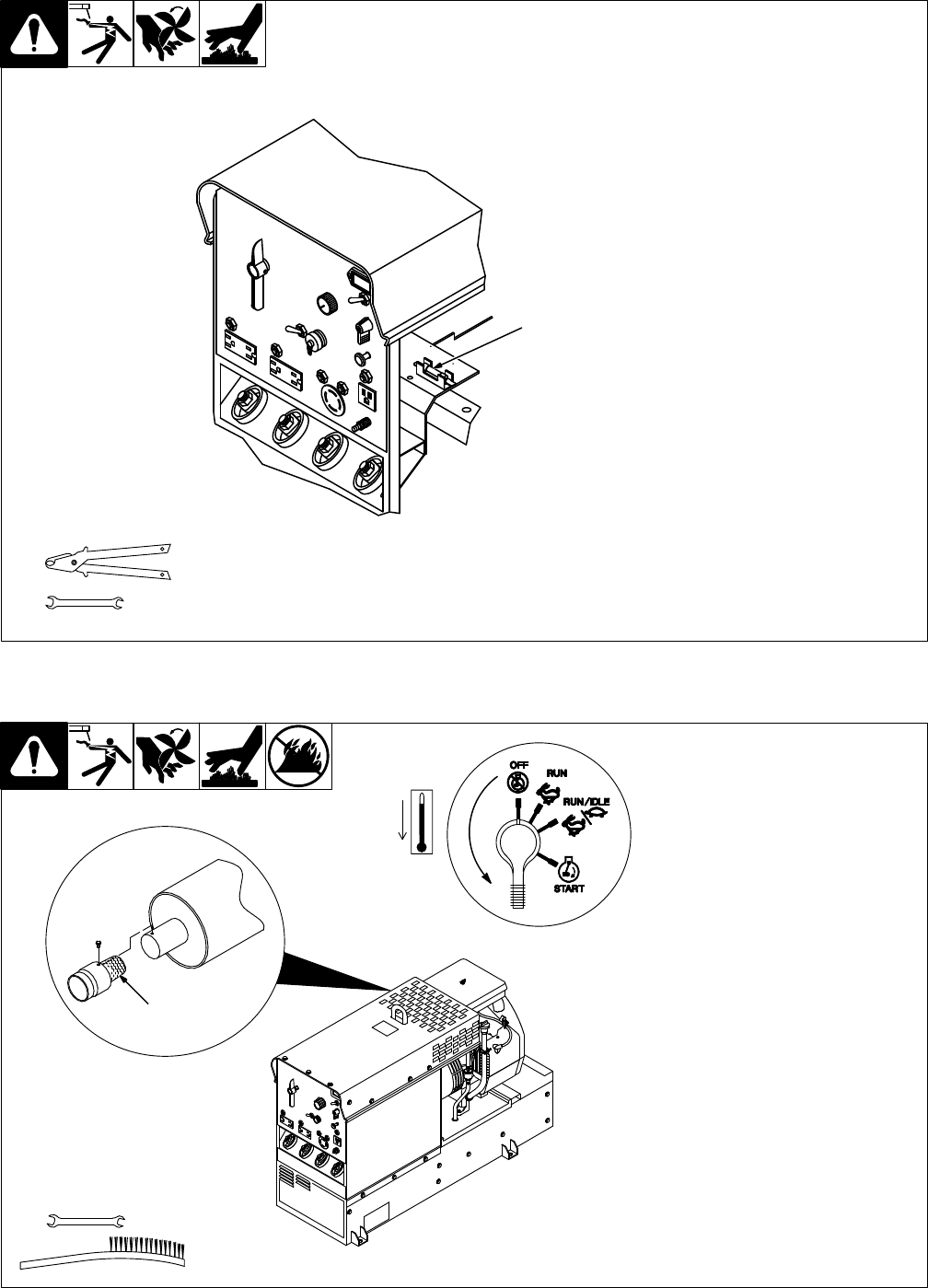
3-1. Front Panel Controls
Ref. ST-168 046
4
2
1 Engine
Control Switch S2
Use switch to start engine, select speed,
and stop engine. In Run/Idle position, en-
gine
runs at power/idle rpm at no load, and
weld/power
rpm under weld or 100 Hz auxil
-
iary
power receptacle load. In Run
position,
engine
runs at weld rpm.
2
Idle Lock Switch S1
Use switch to lock engine at power/idle
speed (see Table). In Unlock position, En-
gine Control switch and optional Remote
Control
switch determine engine speed.
3
Engine Choke Control
Use control to change engine air-fuel mix.
To Start: pull out choke and turn Engine
Control switch to Start position. Release
switch and slowly push choke in when en-
gine starts. Do not crank engine while fly-
wheel
is turning.
To Stop: turn Engine Control switch to Off
position.
4 Remote
Control Switch S4
Use switch to select front panel or remote
amperage
control (see Section 3-2).
5
Ampere Ranges Switch S5
Use
switch to select weld amperage range.
.
For best arc starts, use lowest amper-
age
range possible.
6
Fine Amperage Control R1
Use
control to select
weld amperage within
the range selected by the Ampere Ranges
switch.
Control
may be adjusted while weld
-
ing.
Scale is
for reference only
. W
eld output
would be 88 A DC with control settings as
shown
(50% of 70 to 105 A).
7
Engine Hour Meter HM
15
Using Idle Lock Switch
RUN/IDLE
LOCK
UNLOCK
1860 rpm
RUN/IDLE
OR
RUN
LOCKUNLOCK
(Power/Idle)
1860 rpm
(Power/Idle)
No Load:
3000 rpm
Load:
3000 rpm
(Weld)
6 7
3
(Weld)
TM-428 Page 8
Miller Legend
3-2. Remote Control (Optional)
YWeld output terminals are
energized when Remote
Control switch S4 is in Pan-
el/On
position and engine is
running.
1 Remote
14 Receptacle RC1
Connect
optional remote control
to
RC1
(see Section 2-8).
ST-140 092-B
1
Min (70
A DC)
Max (88
A DC)
Adjust Remote Control
Set Range
Set Percentage
Min = 70
A DC
Percentage Of Range = 50%
Max = 88
A
DC (50% of 70 to 105)
In Example:
Set Switch
3-3. Duty Cycle
SB-115 570
Duty
cycle is the percentage of 10
minutes
that unit can weld at
rated
load
without overheating.
YExceeding duty cycle can
damage unit and void war-
ranty.
Continuous
W
elding
100% Duty Cycle at 225 Amperes AC
TM-428 Page 9
Miller Legend
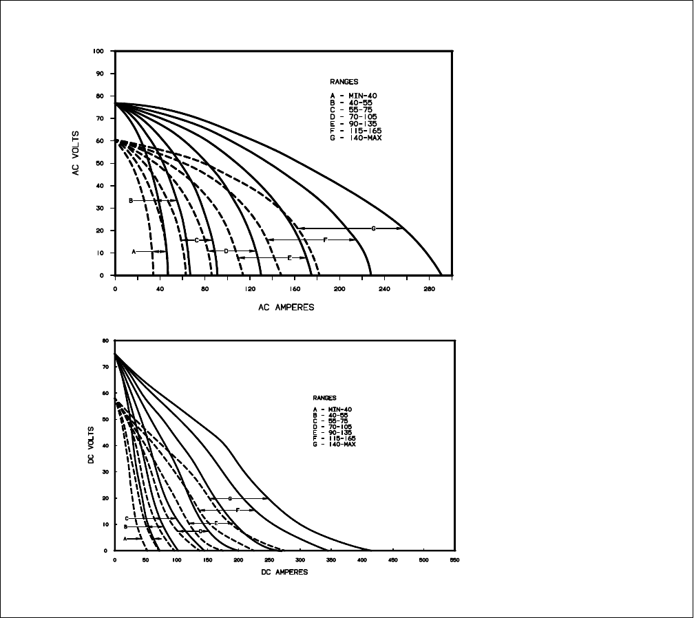
3-4. Volt-Ampere Curves
SB-115 529-A / SB-115 528-A
The volt-ampere curves show the
minimum and maximum voltage
and amperage output capabilities
of
the welding generator
. Curves of
other settings fall between the
curves
shown.
TM-428 Page 10
Miller Legend
SECTION 4 – OPERATING AUXILIARY EQUIPMENT
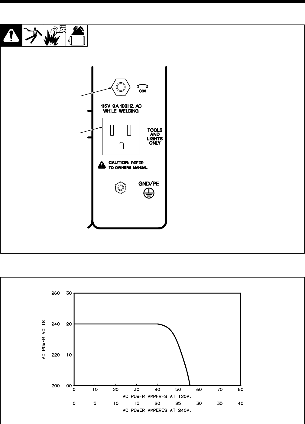
4-1. 100 Hz Auxiliary Power Receptacle And Circuit Breaker
YDo not operate 50/60 Hz or
60 Hz equipment from 100
Hz
receptacle.
11
15 V 9 A 100 Hz AC Recep
-
tacle RC4
Receptacle supplies single-phase
power at weld speed only. Total
output
available is 1 kV
A/kW.
2 Circuit Breaker CB3
CB3 protects receptacle from
overload.
If CB3 opens, receptacle
does
not work.
2
1
Ref. ST-168 046
4-2. AC Auxiliary Power Curve
SB-115 571
TM-428 Page 1
1
Miller Legend
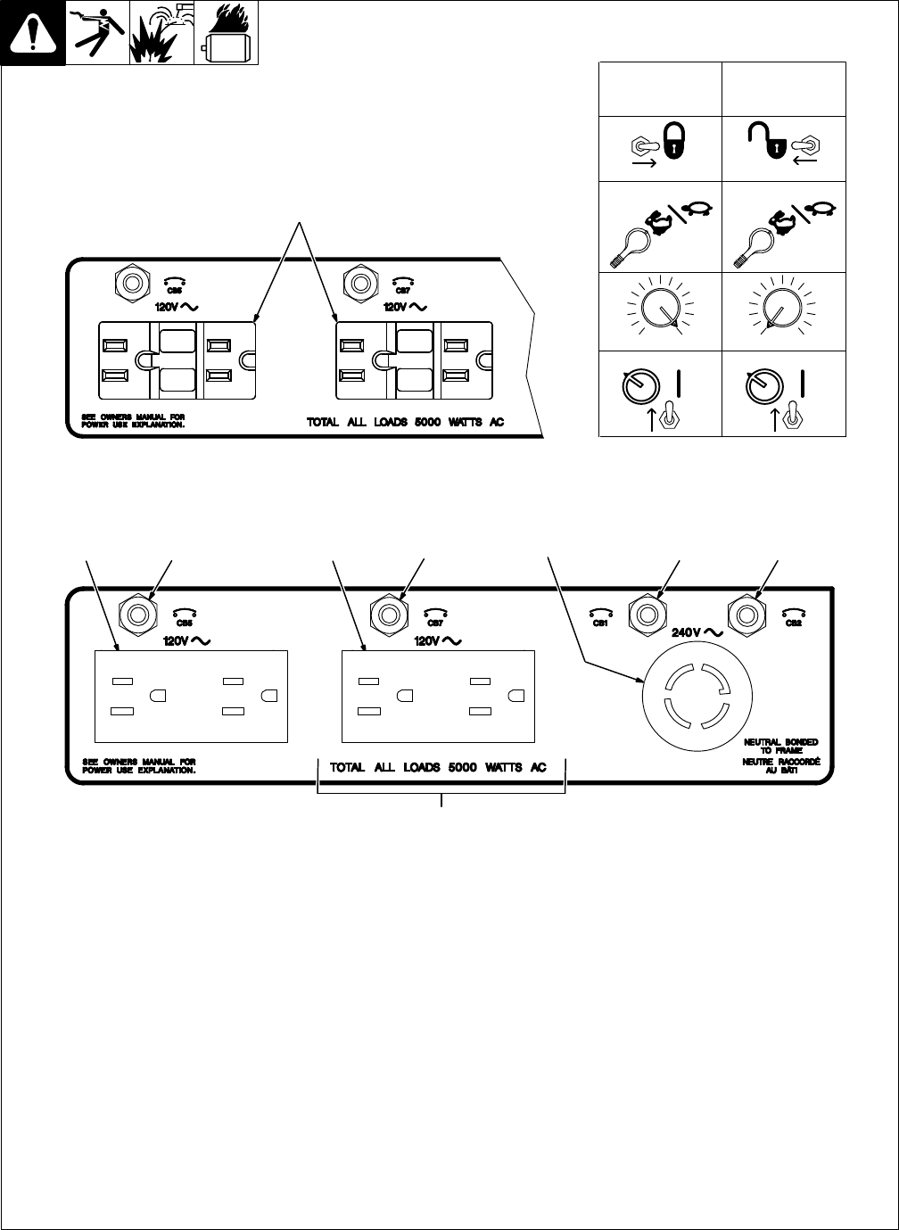
4-3. 60 Hz Auxiliary Power Receptacles And Circuit Breakers
Ref. ST-168 046
57812
9
3
4
6
YIf unit does not have GFCI recep-
tacles, use GFCI-protected exten-
sion
cord.
1 120
V 15 A AC
Duplex Receptacle RC1
2
120 V 15 A AC Duplex Receptacle RC2
3 240
V 30 A T
wistlock Receptacle RC3
Receptacles supply 60 Hz single-phase
power at power/idle speed only. Maximum
output
from each duplex receptacle
is is 2.5
kVA/kW
. Maximum output from twistlock re
-
ceptacle is 5 kVA/kW. For 60 Hz auxiliary
power,
set controls as shown in table.
4
120 V 15 A AC Duplex GFCI Recep
-
tacles GFCI1 And GFCI2 (Optional)
If
a
ground fault is detected, the GFCI recep
-
tacle Reset button pops out and the circuit
opens to disconnect the faulty equipment.
Check
for damaged tools, cords, plugs, etc.
connected
to the receptacle. Press button to
reset
receptacle and resume operation.
.
At least once a month, run engine at
power/idle
speed and press T
est
button
to verify GFCI is working properly.
5 Circuit Breaker CB5
6 Circuit Breaker CB7
CB5 protects RC1 and CB7 protects RC2
from
overload. If CB5 or CB7 opens, the re
-
ceptacle does not work. Press button to re-
set
breaker
.
7 Circuit Breaker CB1
8 Circuit Breaker CB2
CB1 and CB2 protect all the 60 Hz recep-
tacles from overload. If CB1 or CB2 opens,
the 240 volt receptacle and one of the 120
volt receptacles does not work. 120 volts
may still be present at the 240 volt recep-
tacle.
Press button to reset breaker
.
9T
otal Auxiliary Power Output
Combined output of receptacles limited to
the 5 kV
A/kW output of the generator:
EXAMPLE:
If 10 A is drawn from a 120 V du
-
plex
receptacle, only 16 A is available at the
240
V receptacle:
(120
V x 10 A) + (240 V x 16 A) = 5.0 kV
A/kW
PANEL
ON
0 100
LOCK UNLOCK
RUN/IDLE RUN/IDLE
PANEL
ON
0 100
For 60 Hz
Auxiliary Power
While W
elding
For 60 Hz
Auxiliary
Power Only
TM-428 Page 12
Miller Legend
1 Engine
Supplies force to turn revolving
fields.
2 Revolving
Fields (Rotor)
Turn
at 1860 rpm maximum for pow
-
er/idle and 3000 rpm maximum for
weld.
The speed and excitation cur
-
rent of the field coils determine volt
-
ages in stator windings.
3
Stator Windings
Supply power to exciter, auxiliary
power,
and weld circuits.
4
Fuse F1
Protects exciter excitation winding
from
overload.
5
Integrated Rectifier SR2
Changes ac output of stator wind-
ings
to dc to supply excitation current
to
the exciter revolving field.
6
Control Relay CR5
Energizes
when voltage is present in
exciter stator to disconnect field
flashing circuit.
7
Idle Module PC1 And Idle Lock
Switch S1
PC1 and S1 control engine speed.
Without
a signal from CT1, PC1 low
-
ers engine speed to power/idle rpm.
8 Throttle
Solenoid TS1
Increases
engine speed to weld rpm
when
energized.
9
Current T
ransformer CT1
Senses output from either weld or
100 Hz auxiliary power windings,
and signals PC1 to increase to or
maintain
weld rpm.
10 Control Relays CR2, CR3, CR4
CR2
energizes at weld rpm to supply
power
to throttle solenoid TS1.
CR3 energizes at power/idle rpm to
bypass
fine amperage control R1.
CR4 energizes at power/idle rpm to
provide 50/60 Hz auxiliary power
output.
11 Voltage
Regulator Board PC2
And T
ransformer T1
PC2 monitors 50/60 Hz auxiliary
power
voltage through T1, and main
-
tains
proper output by adjusting
field
current.
12 Capacitor
Board PC5, Remote
14 Receptacle RC1, Remote
Control Board PC3
PC5
protects unit from high frequen
-
cy.
RC1
connects remote amperage
and contactor control to unit through
control
board PC3.
SECTION 5 – THEORY OF OPERATION
Voltage
Regulator
Board PC2
Current
Transformer
CT1
Circuit
Breaker
CB3
100 Hz
Auxiliary Power
Receptacle RC4
Fuse
F1
Integrated
Rectifier SR2
Revolving
Fields (Rotor)
Fine
Amperage
Control R1
Remote Control
Switch S4
Remote 14
Panel
Remote
Control Board
PC3
Capacitor Board
PC5
And Remote 14
Receptacle RC1
Engine
Idle Module
Control Relays
CR2, CR3, CR4
Idle Lock
Switch S1
12
1
7
10
5
716
17
♦
13♦
12♦
4
11
9
18
2
PC1
CR3
Throttle
8
Solenoid
TS1
Control
Relay
6
CR5
♦
Voltage
Regulator 60 Hz Auxiliary
Power
Exciter
Stator Windings
3
Weld
100 Hz
Auxiliary
Power
TM-428 Page 13
Miller Legend
13
Remote Control Switch S4
Selects
Panel or remote
amperage
control.
14 Circuit Breakers CB1, CB2,
CB5, And CB7
Protect 50/60 Hz auxiliary power
receptacles RC1, RC2, and RC3
from
overload.
15
50/60 Hz Auxiliary Power Re
-
ceptacles RC1, RC2, And
RC3
Provide connection points and
power
for auxiliary equipment.
16 Circuit Breaker CB3
Protects
100 Hz auxiliary power
re
-
ceptacle
RC4 from overload.
17 100 Hz Auxiliary Power Re-
ceptacle RC4
Provides connection point and
power for auxiliary equipment
while
welding.
18
Fine Amperage Control R1
Adjusts
amperage
within range se
-
lected by Ampere Ranges switch
S5.
19 Ampere
Ranges Switch S5
Selects coarse range of weld out-
put
from weld stator
.
20 Reactor AC-Z
Tapped reactor limits weld output
and
provides coarse ranges.
21
Main Rectifier SR1
Changes ac output from weld
windings
to dc.
22
Stabilizer DC-Z
Smooths out current to dc weld
output
terminals.
23
HF Filter Board PC4
Protects unit from high frequency
.
24
Positive (+) And Negative (–)
DC W
eld Output T
erminals
Provide dc weld output.
25
Electrode And W
ork AC Weld
Output T
erminals
Provide ac weld output.
Stabilizer
Main
Rectifier
SR1
Ampere
Ranges
Switch S5
Reactor
AC-Z
DC-Z
HF Filter
Board
PC4
Positive (+)
And
Negative (–) DC
W
eld Output
Terminals
Transformer
T1
Circuit
Breakers
CB1, CB2,
50/60 Hz
Auxiliary Power
Receptacles
RC1, RC2, RC3
19
20
21
22
11
14 15
23 25
24
Electrode
And
Work AC Weld
Output
Terminals
AC Or DC Control Circuits
Mechanical Coupling
W
eld Current Circuit
Magnetic Coupling
♦Optional
CR4
CB5, CB7

TM-428 Page 14
Miller Legend
NOTES
TM-428 Page 15
Miller Legend
SECTION 6 – TROUBLESHOOTING
6-1. Troubleshooting Tables
A. Welding
.
See Sections 6-2 and 6-3 for test
points and values and Section 10
for
parts location.
Trouble Remedy
No weld output.
Check fuse F1, and replace if necessary (see Section 8-6).
Check integrated rectifier SR2, and replace if necessary
.
Check diode D4, and replace if necessary
.
Clean slip rings, and install new brushes if necessary (see Section 6-15).
Disconnect leads 21, 23, and 33 from brushes, and check continuity across slip rings. Replace rotor
if necessary.
Check resistance and connections of resistors R2 and R4; R2 and R4 are each 12 ohms
±10%.
Re
-
place resistor(s) if necessary
. Adjust R2 and R4 according to Section 6-16.
Check
resistance and connections of Fine Amperage Control
R1; R1 is 0 to 30 ohms
±
10%. Replace
R1
if necessary (see Section 3-1).
Disconnect
leads 22 and 29 from SCR/integrated rectifier SR2, and check for continuity between leads
22
and 29. Replace exciter stator if necessary
.
For
units with optional remote control, check capacitor C5 for a short or open, and check for proper con
-
nections. Replace C5 if necessary.
Check voltage regulator board PC2 and connections, and replace if necessary (see Section 6-9).
No or erratic weld output.
Clean and tighten weld connections both inside and outside unit.
Check engine speed, and adjust if necessary (see Section 8-5).
Check
to make sure Ampere Ranges switch S5 is not between positions. Check continuity of S5, and
replace if necessary.
Check
reactor AC-Z for signs of winding failure. Check continuity across windings, and check for proper
connections. Replace AC-Z if necessary.
Check
resistance and connections of Fine Amperage control R1; R1 is 0 to 30 ohms
±
10%. Replace
R1 if necessary.
Disconnect leads 21, 23, and 33 from brushes, and check continuity across slip rings. Replace rotor
if necessary.
No or erratic DC weld output only
.
Check modular main rectifier SR1, and replace if necessary
.
Check stabilizer DC-Z for signs of winding failure. Check continuity across windings, and check for
proper connections. Replace DC-Z if necessary.
Low or high weld output.
Check engine speed, and adjust if necessary (see Section 8-5).
Adjust resistor R4 slider until 128 to 132 volts ac is obtained at 100 Hz receptacle RC4 (see Section
6-16).
Adjust
resistor R2 slider until proper open-circuit-voltage is obtained at
weld output terminals (see Sec
-
tion
6-16).
Check
resistance
and connections of resistor R3 on suppressor R3, VR1 module; R3 is 1000 ohms
±
10%.
Replace R3, VR1 module if necessary
.
Check
reactor AC-Z for signs of winding failure. Check continuity across windings, and check for proper
connections. Replace AC-Z if necessary.

TM-428 Page 16
Miller Legend
B. 50 Or 60 Hz Auxiliary Power
Trouble Remedy
No auxiliary power output at recep-
tacles RC1, RC2, or RC3.
Run engine at power/idle speed.
Reset circuit breakers CB1 and CB2. Effective with Serial No. KE629034, also reset circuit breakers
CB5
and CB7 (see Section 4-3).
Check
receptacles RC1, RC2, RC3 for continuity and proper connections. Replace receptacle(s) if nec
-
essary.
Check
connections to terminal strip 1T
.
Clean slip rings, and install new brushes if necessary (see Section 6-15).
Check
coil voltage and connections of control relay CR4. Check continuity of coil and condition of
con
-
tacts. Replace CR4 if necessary.
Check diode D4, and replace if necessary
.
Check idle board/module PC1 and connections (see Section 6-5).
Check
control transformer T1 for signs of winding failure. Check continuity across windings, and check
for
proper connections. Check primary and secondary voltages. Replace T1 if necessary
.
Disconnect leads 21, 23, and 33 from brushes, and check continuity across slip rings. Replace rotor
if necessary.
Disconnect
leads 48 and 49
from voltage regulator board PC2, and check continuity between leads 48
and
49. Disconnect leads 50, 51, 52, and 53 from stator
. Check continuity between leads 50 and 51,
and 52 and 53. Replace stator if necessary
.
Low auxiliary power output.
Check connections to terminal strip 1T
.
Clean slip rings, and install new brushes if necessary (see Section 6-15).
Check integrated rectifier SR2, and replace if necessary
.
Check
coil voltage and connections of control relay CR3. Check continuity of coil and condition of
con
-
tacts. Replace CR3 if necessary.
Check voltage regulator board PC2 and connections, and replace if necessary
.
High auxiliary power output.
Check engine speed, and adjust if necessary
.
Check voltage regulator board PC2 and connections, and replace if necessary (see Section 6-9).
C. 100 Hz Auxiliary Power
Trouble Remedy
No
auxiliary power output at receptacle
RC4. Run
engine at weld speed.
Reset circuit breaker CB3 (see Section 4-1).
Check receptacle RC4 for continuity and proper connections. Replace receptacle if necessary
.
Disconnect
leads 90, 91, 92, and 93 from stator
. Check continuity between leads 90 and 91, and 92 and
93. Replace stator if necessary.
Check diode D4, and replace if necessary
.

TM-428 Page 17
Miller Legend
D. Engine
Trouble Remedy
Engine will not start.
Check fuel level (see Section 2-4).
Check battery and engine charging system according to engine manual.
Check continuity of Engine Control switch S2, and replace if necessary
.
See engine manual.
Engine starts but
stops as soon as En
-
gine Control switch S2 returns to Run
position.
Check
oil
level (see Section 2-4). Check low oil pressure shutdown switch S3 (see engine parts manual
for
location). S3 should close when engine is running.
Check
and refill crankcase with proper
viscosity oil for operating temperature, if necessary (see engine
manual).
Check
continuity of Engine Control switch S2, and replace if necessary
.
Engine stopped during normal opera-
tion. Check
oil
level (see Section 2-4). Check low oil pressure shutdown switch S3 (see engine parts manual
for
location). S3 should close when engine is running.
Check continuity of Engine Control switch S2, and replace if necessary
.
Battery discharges between uses.
Make
sure Engine Control switch
S2 is placed in the Of
f position when engine is not in use (see Section
3-1).
Prior
to Serial No. KA780044, check fuse F2 and replace if necessary
.
Clean battery, terminals and posts with baking soda solution; rinse with clear water
.
Periodically recharge battery (approximately every 3 months).
Check voltage regulator according to engine manual.
Replace battery
.
Engine idles, but does not come up to
weld
speed.
W
ait 10 seconds for throttle solenoid circuit breaker CB4 to reset (see Section 8-6).
Place Idle Lock switch S1 in Unlock position (see Section 3-1).
Check continuity and connections of current transformer CT1, and replace if necessary
.
Check continuity of Engine Control switch S2, and replace if necessary
.
Check
coil voltage and connections of control relay CR2. Check continuity of coil and condition of
con
-
tacts. Replace CR2 if necessary.
Check diode D6 in throttle solenoid TS1 circuit, and replace if necessary
.
Check resistance at throttle solenoid TS1 terminals. With plunger out, resistance is less than 1 ohm.
With plunger bottomed, resistance is 17 ohms
±10%.
Check throttle linkage for smooth, non-binding operation.
Check idle board/module PC1 and connections, and replace if necessary (see Section 6-5).
Engine does not return to idle speed.
Remove weld load.
Check continuity of Engine Control switch S2, and replace if necessary
.
Check throttle linkage for smooth, non-binding operation.
Unstable or sluggish engine speeds.
Readjust throttle linkage if necessary
.
T
une-up engine according to engine manual.
TM-428 Page 18
Miller Legend
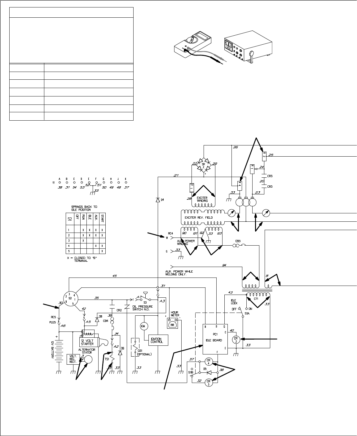
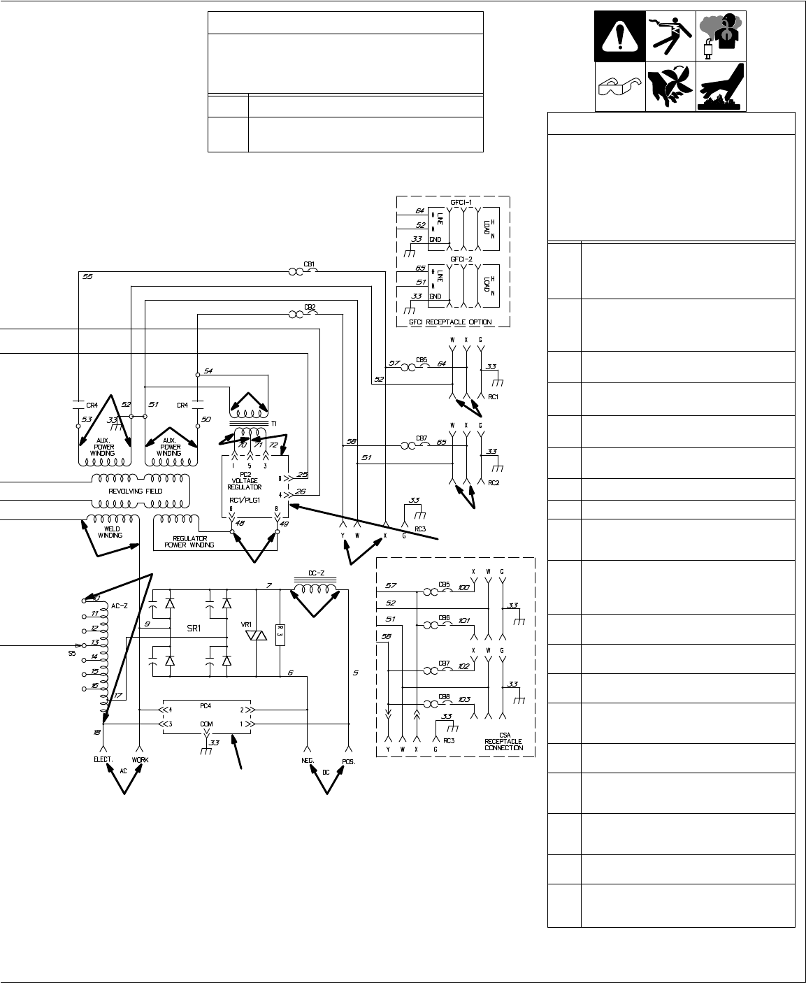
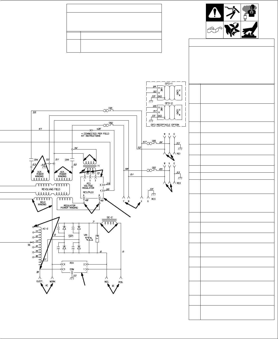
6-2. Troubleshooting Circuit Diagram For Welding Generator
Test
Equipment Needed:
Resistance Values
a) Tolerance – ±10% unless specified
b) Condition – 70°F (21°C); cold machine
(no warm-up)
c) Wiring Diagram – see Section 9
d) Stop engine before checking resistance
R1 29
ohms
R2
34 ohms
R3
35 ohms
R4
2 ohms
R5
2 ohms
R6 thru R17
Less than 1 ohm
R18
Pull: Less than 1 ohm Hold: 16.5 ohms
CR2 energized
Field current
at weld rpm
V14/R17
V15
V16/ V17/
R1 R2
I1 I2
V11,
V12,
V13/R12
V18
V19
R16 R15 R14 R13
Throttle
control relay
control relay CR3
and auxiliary power
control relay CR4
energized at
power/idle rpm
See Section
6-16 for R2 and
R4 adjustment
See Section 6-5
for PC1 data
R18
TM-428 Page 19
Miller Legend
SC-168 053-A
Amperage Readings
a) Tolerance – ±5% unless specified
b) Condition – 70°F (21°C); cold machine
(no warm-up); no load
I1 3
amps dc
I2
1.8 amps dc (R1 at min.)
3.1 amps dc (R1 at max.)
Voltage Readings
a) Tolerance – ±10% unless specified
b) Condition – 70°F (21°C); cold
machine (no warm-up); no load
c) Reference – to circuit common
(lead 33) unless noted
d) Wiring Diagram – see Section 9
V1 DC/CC
OCV at weld rpm:
58 volts dc (R1 at min.)
70 volts dc (R1 at max.)
(Do not exceed 72 volts dc)
V2 AC/CC OCV
, at weld rpm:
65 volts ac (R1 at min.)
80 volts ac (R1 at max.)
(Do not exceed 80 volts ac)
V3
At RC3 at power/idle rpm:
244 volts ac
±
5% (50 or 60 Hz)
V4
At RC2 at power/idle rpm:
122 volts ac
±
5% (50 or 60 Hz)
V5
At RC1 at power/idle rpm:
122 volts ac
±
5% (50 or 60 Hz)
V6
AC input to transformer T1: 122 volts ac
(power/idle rpm), 0 volts ac (weld rpm)
V7
AC output to PC2: 21 volts ac
±5%
V8
AC output to PC2: 21 volts ac
±5%
V9
AC output from Regulator Power
Winding (power/idle rpm)
158 volts ac
±5%
V10
AC output from W
eld Winding at
weld rpm: 65 volts ac (R1 at min.), 80
volts ac (R1 at max.) (Do not exceed 80
volts ac)
V11
At rated DC weld load: At least
1 volts ac
V12
At weld rpm and 100 watt light bulb load
applied: 3 volts ac or greater
V13 Idle Lock switch S1 in Lock:
0 volts ac at all times
V14
AC output from Exciter Winding
80 volts ac (power/idle rpm)
145 volts ac (weld rpm)
V15
At RC4 at weld speed: at least 120
volts ac (Do not exceed 132 volts ac)
V16
Auxiliary power winding at weld rpm:
at least 120 volts ac (Do not exceed
132 volts ac)
V17
Auxiliary power winding at weld rpm:
at least 120 volts ac (Do not exceed
132 volts ac)
V18
Battery output whenever engine is
running: 14 volts dc.
V19
AC Alternator output:
17 volts ac (power/idle rpm)
39 volts ac (weld rpm)
V5
V4
V3
V2/C/D V1/A/B
V9/R9
V10/R8
V7/
V8/
V6/R3
R5
R4
R10
R11
R6
R7
See Sections 6-7
thru 6-9 for PC2 data
See Section 6-4 for
waveforms A thru D
See Section 5 for
PC4 information
TM-428 Page 20
Miller Legend
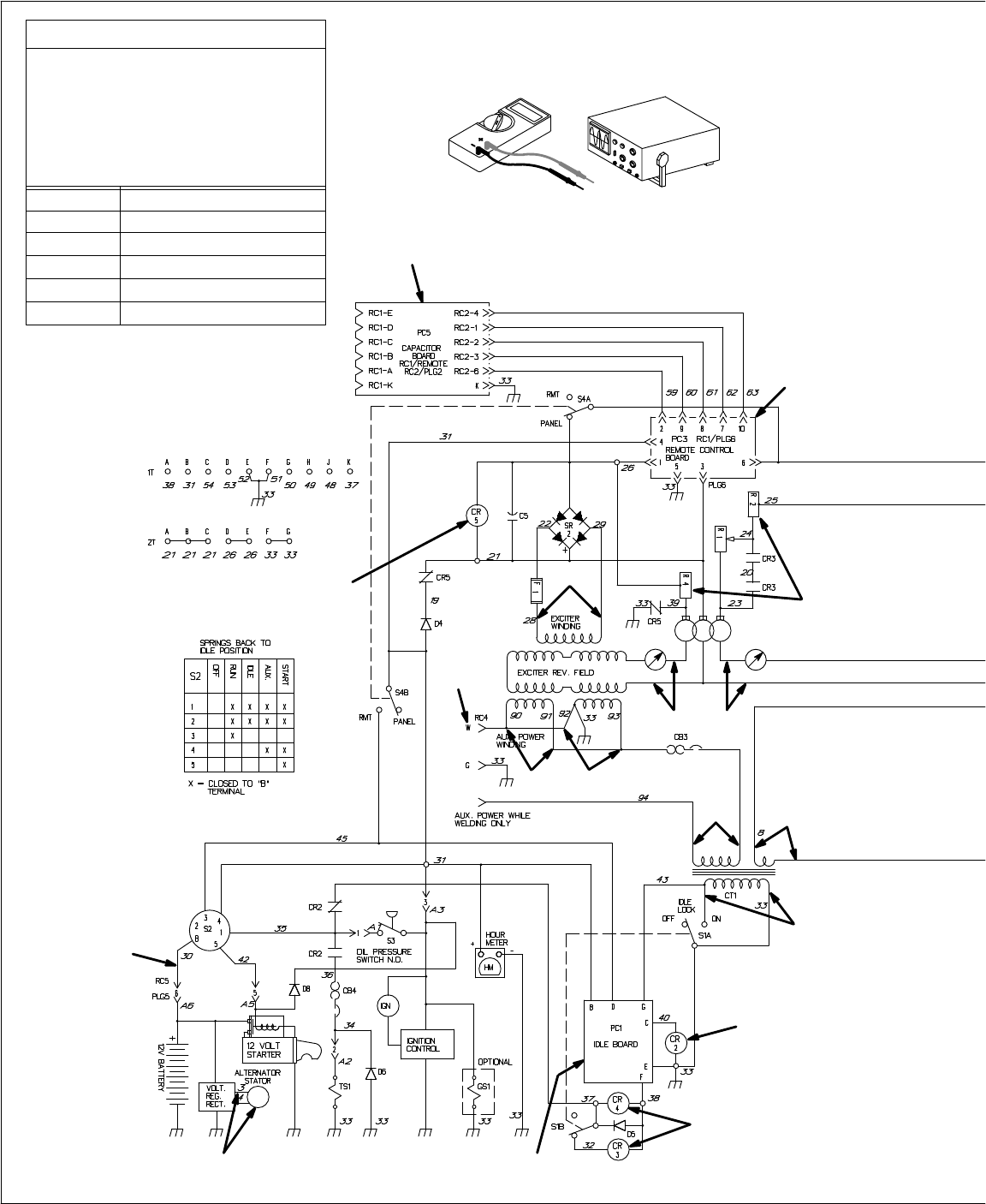
6-3. Troubleshooting
Circuit Diagram For W
elding Generator W
ith Optional Remote Control
Test
Equipment Needed:
Resistance Values
a) Tolerance
–
±
10% unless specified
b) Condition – 70°F (21°C); cold
machine (no warm-up)
c) Wiring Diagram – see Section 9
d) Stop engine before checking
resistance
R1 29
ohms
R2
34 ohms
R3
35 ohms
R4
2 ohms
R5
2 ohms
R6 thru R17
Less than 1 ohm
CR2 energized
Field current
at weld rpm
Throttle
control relay
control relay CR3
and auxiliary power
control relay CR4
energized at
power/idle rpm
V14/R17
V15
V16/ V17/
R1 R2
I1 I2
V1
1, V12,
V13/R12
V18
V19
R16 R15
R14 R13
Field flashing
disconnect relay CR5
See Section
6-11
for PC3 data
See Section 6-13
for PC5 data
See Section 6-5
for PC1 data
See Section
6-16 for R2 and
R4 adjustment
TM-428 Page 21
Miller Legend
SC-168 054-A
Amperage Readings
a) Tolerance – ±5% unless specified
b) Condition – 70°F (21°C); cold machine
(no warm-up); no load
I1 3
amps dc
I2
1.8 amps dc (R1 at min.)
3.1 amps dc (R1 at max.)
Voltage Readings
a) Tolerance – ±10% unless specified
b) Condition – 70°F (21°C); cold
machine (no warm-up); no load
c) Reference – to circuit common
(lead 33) unless noted
d) Wiring Diagram – see Section 9
V1 DC/CC
OCV at weld rpm:
58 volts dc (R1 at min.)
70 volts dc (R1 at max.)
(Do not exceed 72 volts dc)
V2 AC/CC OCV
, at weld rpm:
65 volts ac (R1 at min.)
80 volts ac (R1 at max.)
(Do not exceed 80 volts ac)
V3
At RC3 at power/idle rpm:
244 volts ac
±
5% (50 or 60 Hz)
V4
At RC2 at power/idle rpm:
122 volts ac
±
5% (50 or 60 Hz)
V5
At RC1 at power/idle rpm:
122 volts ac
±
5% (50 or 60 Hz)
V6
AC input to transformer T1: 122 volts ac
(power/idle rpm), 0 volts ac (weld rpm)
V7
AC output to PC2: 21 volts ac
±5%
V8
AC output to PC2: 21 volts ac
±5%
V9
AC output from Regulator Power
Winding (power/idle rpm)
158 volts ac
±5%
V10
AC output from W
eld Winding at
weld rpm: 65 volts ac (R1 at min.), 80
volts ac (R1 at max.) (Do not exceed 80
volts ac)
V11
At rated DC weld load: At least
1 volts ac
V12
At weld rpm and 100 watt light bulb load
applied: 3 volts ac or greater
V13 Idle Lock switch S1 in Lock:
0 volts ac at all times
V14
AC output from Exciter Winding
80 volts ac (power/idle rpm)
145 volts ac (weld rpm)
V15
At RC4 at weld speed: at least 120
volts ac (Do not exceed 132 volts ac)
V16
Auxiliary power winding at weld rpm:
at least 120 volts ac (Do not exceed
132 volts ac)
V17
Auxiliary power winding at weld rpm:
at least 120 volts ac (Do not exceed
132 volts ac)
V18
Battery output whenever engine is
running: 14 volts dc.
V19
AC Alternator output:
17 volts ac (power/idle rpm)
39 volts ac (weld rpm)
V5
V4
V3
V2/C/D V1/A/B
V9/R9
V10/R8
V7/
V8/
V6/R3
R5
R4
R10
R11
R6
R7
See Section 6-4 for
waveforms A thru D
See Section 5 for
PC4 information
See Sections 6-7
thru 6-9 for PC2 data
TM-428 Page 22
Miller Legend
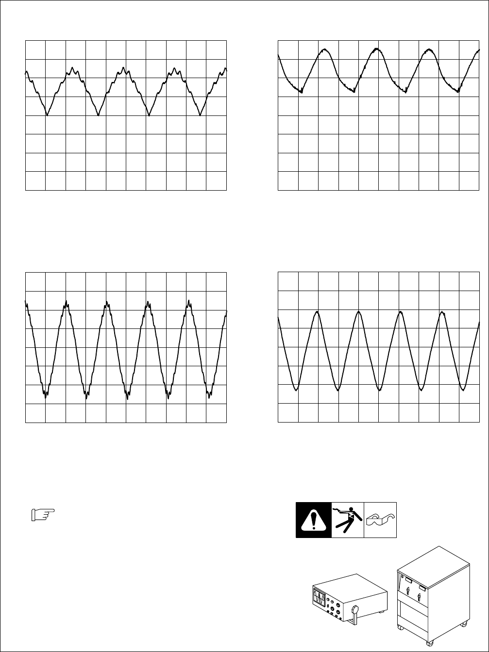
6-4. Waveforms For Sections 6-2 And 6-3
Test
Equipment Needed:
W
aveforms shown are for 60 Hertz models;
waveforms for 50 Hertz models are similar
.
2 ms 50 V
A. DC Open-Circuit
V
oltage, Ampere Ranges
Switch S5 In Max Position
2 ms 10 V
B. DC Weld Output, 25 Volts DC, 100 Am-
peres,
Ampere Range Switch S5 In
70-105
Position (Resistive Load)
5 ms 50 V
C. AC Open-Circuit Voltage, Ampere Ranges
Switch S5 In Max Position
5 ms 20 V
D. AC Weld Output, 25 Volts AC, 100 Amperes,
Ampere Range
Switch S5 In 70-105 Position
(Resistive Load)
gndgnd
gndgnd
TM-428 Page 23
Miller Legend
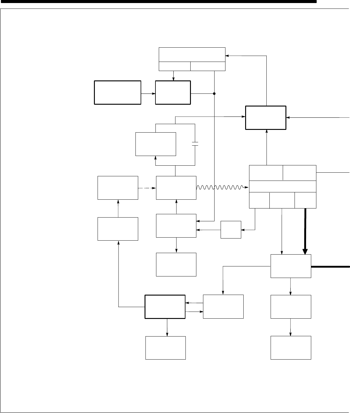
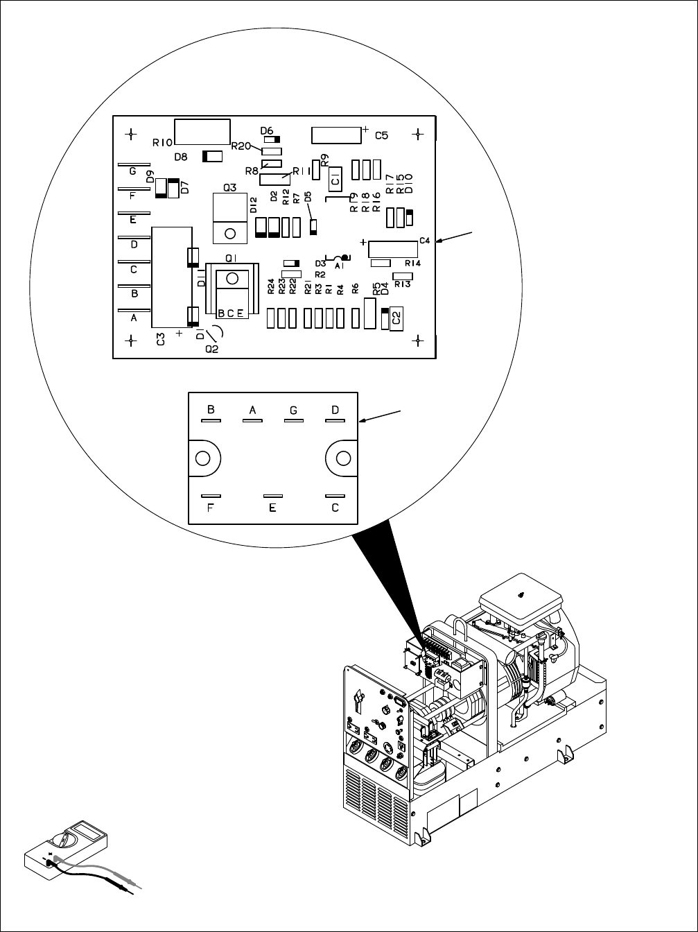
6-5. Idle Control Board/Module PC1 Testing Information
Ref. ST-800 698-A / SC-113 702-A
Be sure plugs are secure before
testing.
See Section 6-6 for specif
-
ic
values during testing.
1
Idle Control Board PC1 (Prior
T
o Serial No. JH300534)
2
Idle Module PC1 (Ef
fective
With Serial No. JH300534)
T
est Equipment Needed:
1
2
OR

TM-428 Page 24
Miller Legend
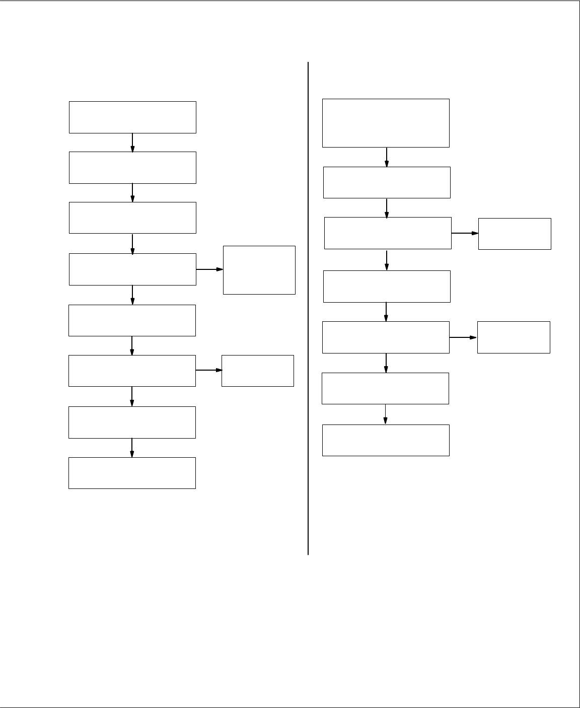
NO
NO
NO
YES
Connect meter (AC) between
terminal G and terminal E.
0 (zero) volts dc
present after 12 to 18 seconds?
Connect meter (DC) between
terminal C (+) and terminal E (–).
0 (zero) volts ac present?
YES
Reinstall cover.
Check for internal
load such as
shorted diode in
Connect a 100 watt light bulb to
100 Hz ac receptacle.
Connect meter (AC) between
terminal G and terminal E.
Minimum of 1 volt ac present?
YES
Disconnect 100 watt light bulb
and meter leads.
Connect meter (DC) between
terminal C (+) and terminal E (–).
+12 volts dc present?
YES
Reinstall cover.
Check connections
to current
transformer CT1.
Engine does not go to power/idle rpm
with no weld load applied. Engine does not go to weld rpm with
load applied.
NO
main rectifier SR1.
NO
0 (zero) volts dc present?
Connect meter (DC) between
terminal D (+) and E (–).
YES
NO
Connect meter (DC) between
terminal B (+) and terminal E (–).
YES
+12 volts dc present?
Check connections
to Engine Control
switch S2 and
ground connection
(lead 33).
Start
engine. Place Engine Control
switch S2 in Run/Idle position.
Check connections
to Engine Control
switch S2.
Start engine. Place Engine
Control switch in Run/Idle position.
Start engine. Place Engine Control
switch S2 in Run/Idle position; Idle
Lock switch S1 in Unlock position.
Check throttle solenoid TS1
linkage.
Check circuit breaker CB4, throttle
solenoid TS1 connections and
linkage, and control relay CR2.
Replace idle
board/module
PC1
Replace idle
board/module
PC1
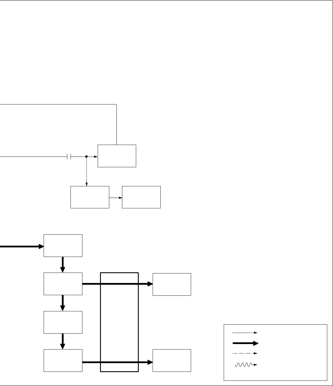
6-6. Troubleshooting Flowcharts For Idle Control Board/Module PC1
TM-428 Page 25
Miller Legend
NO
Reinstall cover.
+12 volts dc present?
YES
Engine does not go to weld rpm with
Engine Control switch S2 in Run position.
NO
YES
+12 volts dc present?
Check connections
to Engine Control
switch S2 and
ground connection
(lead 33).
Start
engine. Place Engine
Control switch S2 in Run position.
Check circuit breaker CB4, throttle
solenoid TS1 connections and
linkage, and control relay CR2.
Connect meter (DC) between
terminals D (+) and E (–).
Prior to Serial No. JH300534,
move W
eld/Power switch S1 to
W
eld position.
Control Relays CR3 and CR4 do not
energize at idle rpm (See Section 5 for
CR3 and CR4 information)
Reinstall cover.
NO
YES
+12 volts dc present?
Connect
meter (DC) between
terminal A (+) and F (–) prior to
Serial No. JH300534, or B (+) and
F (–) ef
fective with Serial No.
JH300534.
Start engine. Place Engine
Control switch in Run position.
NO
YES
0 (zero) volts dc present?
Check control relays
CR3 andCR4.
Place Engine Control switch S2
in Run/Idle position.
Replace idle
board/module
PC1
Replace idle
board/module
PC1
Replace idle
board/module
PC1
Connect meter (DC) between
terminals C (+) and E (–).
TM-428 Page 26
Miller Legend
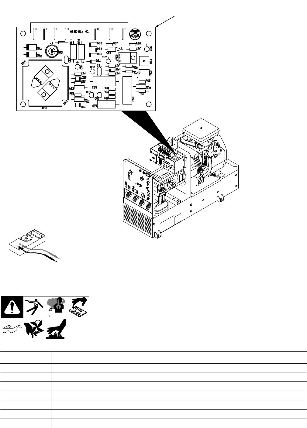
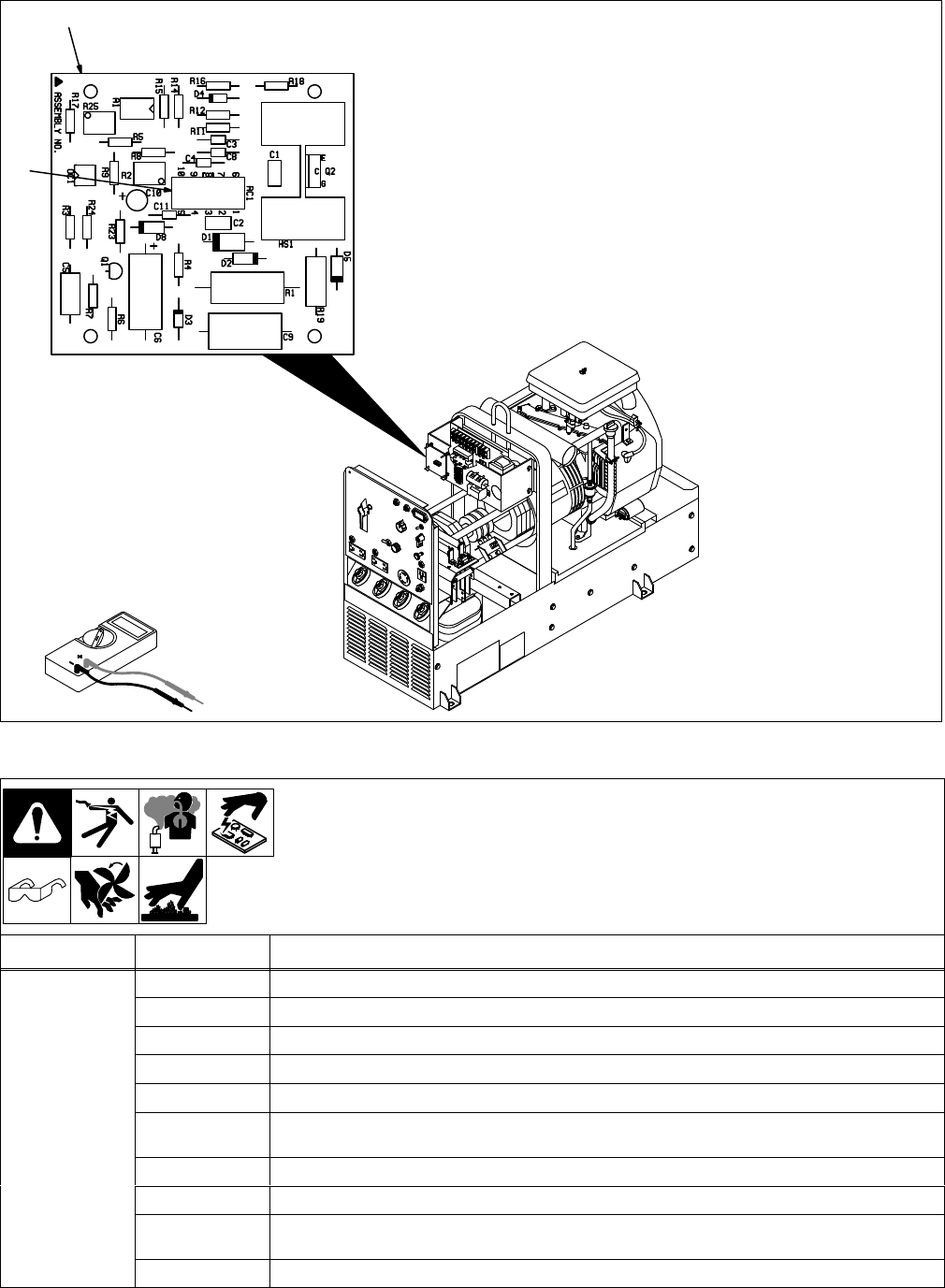
6-7. Voltage Regulator Board PC2 Testing Information Prior To Serial No. KE604176
Ref. ST-800 698-A / SA-099 497-B
Be sure plugs are secure before
testing.
See Section 6-8 for specif
-
ic
values during testing.
1V
oltage Regulator Board PC2
2T
erminals A Thru G
T
est Equipment Needed:
1
2
6-8. Voltage Regulator Board PC2 Test Point Values Prior To Serial No. KE604176
PC2 Voltage Readings
a) Tolerance – ±10% unless
specified
b) Reference
– to circuit com
-
mon
(lead 33) unless noted
Receptacle Value
A Circuit
common
B
18 volts ac input with respect to pin A
C
18 volts ac input with respect to pin A
D
Circuit common
E
130 volts ac input with respect to terminal G at power/idle rpm
F
55 volts dc output with respect to terminal D at power/idle rpm
G
130 volts ac input with respect to terminal E at power/idle rpm
TM-428 Page 27
Miller Legend
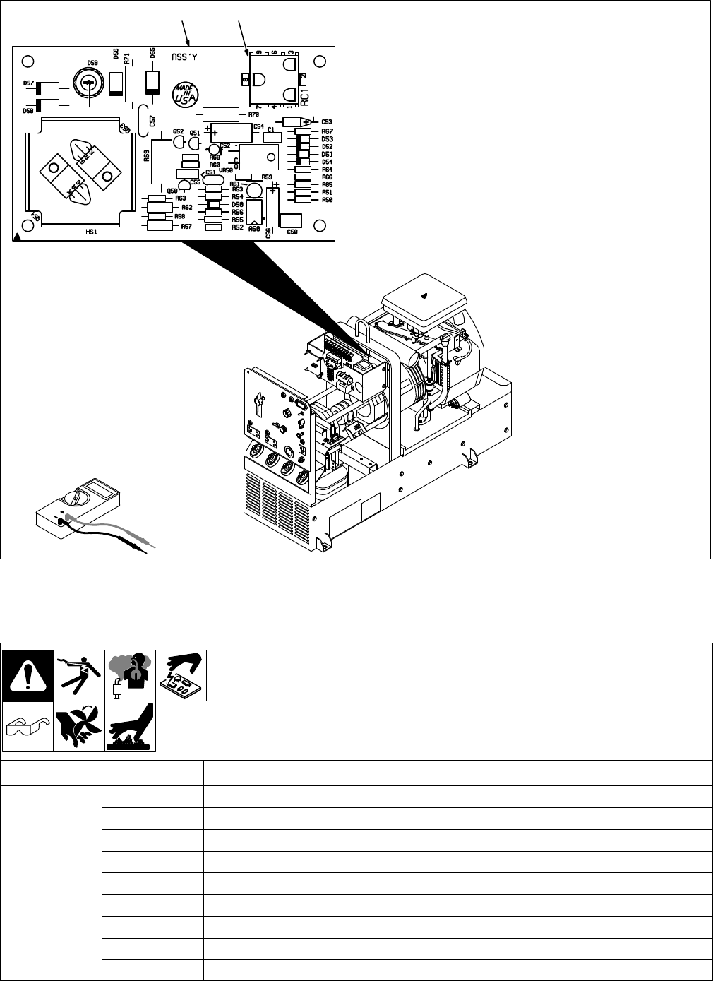
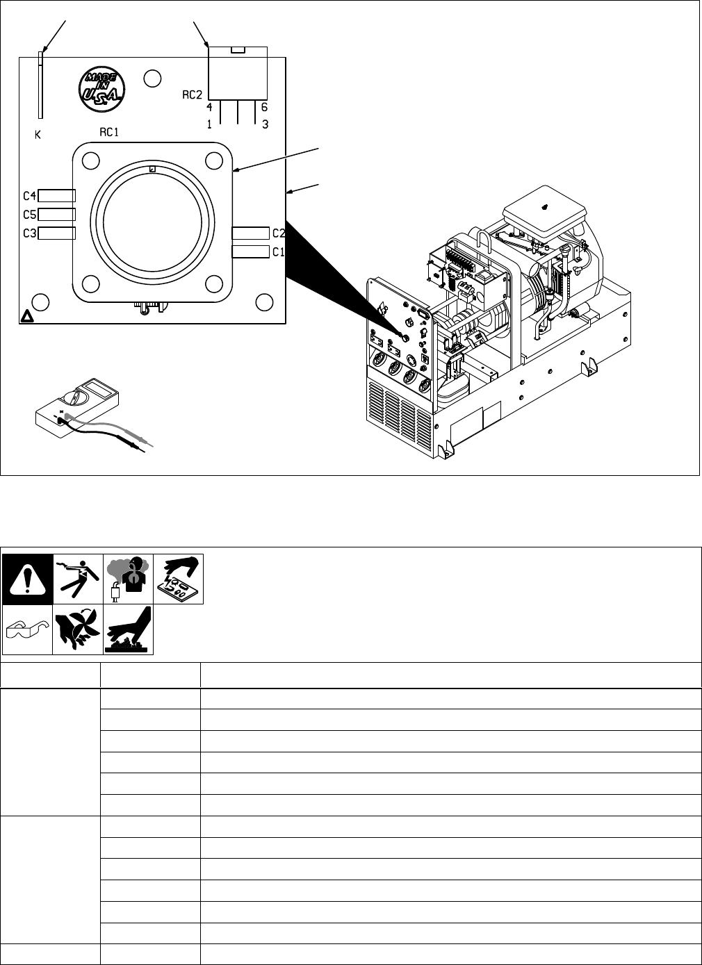
6-9. Voltage Regulator Board PC2 Testing Information Effective With Serial No.
KE604176
Ref. ST-800 698-A / SA-160 889-A
Be sure plugs are secure before
testing. See Section 6-10 for spe-
cific
values during testing.
1V
oltage Regulator Board PC2
2 Receptacle RC1
T
est Equipment Needed:
1 2
6-10. Voltage Regulator Board PC2 Test Point Values Effective With Serial No. KE604176
PC2 Voltage Readings
a) Tolerance – ±10% unless
specified
b) Reference
– to circuit com
-
mon
(lead 33) unless noted
Receptacle Pin Value
RC1 1 18
volts ac input with respect to pin 5
2
Not used
3
18 volts ac input with respect to pin 5
4
Circuit common
5
Circuit common
6
130 volts ac input with respect to pin 8 at power/idle rpm
7
Not used
8
130 volts ac input with respect to pin 6 at power/idle rpm
9
55 volts dc output with respect to pin 4 at power/idle rpm
TM-428 Page 28
Miller Legend
6-11. Optional Remote Control Board PC3 Testing Information
Ref. ST-800 698-A / ST-115 941-L / SA-138 247
Be sure plugs are secure before
testing. See Section 6-12 for spe-
cific
values during testing.
1
Remote Control Board PC3
2 Receptacle RC1
T
est Equipment Needed:
1
2
6-12. Optional Remote Control Board PC3 Test Point Values
PC3 Voltage Readings
a) Tolerance – ±10% unless
specified
b) Reference
– to circuit com
-
mon
(lead 33) unless noted
Receptacle Pin* Value
RC1 1 (A)
Circuit common
2 (B)
Circuit common
3 (C)
+50 volts dc input at power/idle rpm; 100 volts dc input at weld rpm
4 (D)
+12 volts dc input with respect to pin 5 at power/idle or weld rpm
5 (E)
Chassis ground (lead 33)
6 (F)
59 to 6.8 volts dc output with respect to pin 1 from min to max of remote control with remote contac
-
tor control switch closed, 130 volts dc output with remote contactor control switch open
7 (G)
Circuit common
8 (H)
Command reference output, +4.5 volts dc output with respect to pin 7
9 (J)
0 volts dc output with remote contactor control switch closed, +15 volts dc output with remote con
-
tactor control switch open
10 (K)
0 to +4.5 volts dc input from min to max of Fine Amperage control R1 at power/idle rpm
*Letter(s) in parenthesis ( ) is pin letter prior to Serial No. KA840710.
TM-428 Page 29
Miller Legend
6-13.
Optional Remote Capacitor Board PC5 T
esting Information Effective W
ith Serial No.
KD346698
Ref. ST-800 698-A / SA-156 026-C
Be sure plugs are secure before
testing. See Section 6-14 for spe-
cific
values during testing.
1
Capacitor Board PC5
2
Remote 14 Receptacle RC1
3 Receptacle RC2
4T
erminal K
T
est Equipment Needed:
43
1
2
6-14. Optional Remote Capacitor Board PC5 Test Point Values Effective With Serial No.
KD346698
PC5 Voltage Readings
a) Tolerance – ±10% unless
specified
b) Reference
– to circuit com
-
mon
(lead 33) unless noted
Receptacle Pin Value
RC1 A Contact
closure to pin B completes the dc contactor control circuit
B
+15 volts dc output
C
Command reference, +4.5 volts dc output
D
Remote control circuit command
E
Input command signal from potentiometer wiper
, 0 to +4.5 volts dc input
K
Chassis ground (lead 33)
RC2 1
Remote control circuit common
2
Command reference, +4.5 volts dc input
3
+15 volts dc input
4
Command signal from potentiometer wiper
, 0 to +4.5 volts dc output
5
Not used
6
Contact closure to pin 3 completes contactor control circuit
Terminal K
Chassis ground (lead 33)
TM-428 Page 30
Miller Legend
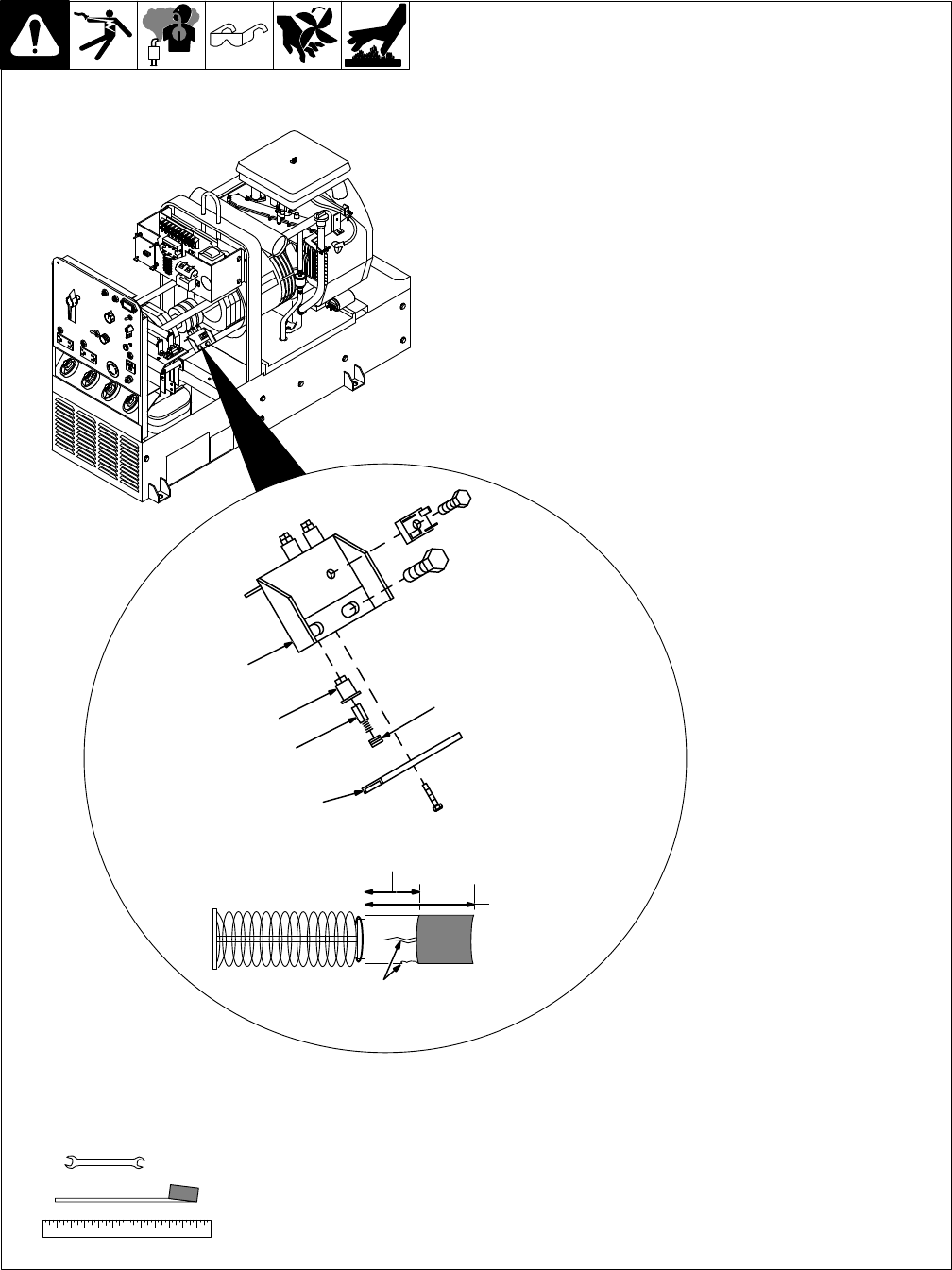
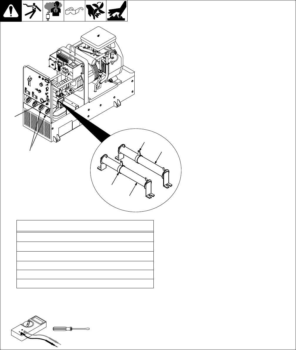
6-15. Replacing Brushes And Cleaning Slip Rings
A. Checking Brushes And Cleaning Slip Rings
ST-800 698-A / Ref. ST-115 942-F / S-0233-A
Stop
engine and allow to cool.
1
Brush Holder Retaining Bar
2 Brush Holder Bracket
Remove brush holder bracket.
Keep
hardware for reinstallation.
3
Brush Holder
4
Brush With Spring
5
Brush Holder Cap
Mark and disconnect leads at
caps, and remove brushes from
bracket.
Replace brushes if damaged, or if
brush
is
at or near minimum length.
6 Slip Rings
Inspect slip rings. Under normal
use,
rings turn dark brown.
If
slip rings are corroded or surface
is uneven, insulate brush leads,
start
engine,
and clean rings with a
commutator stone. Remove as
little
material as possible. Stop en
-
gine.
Install brushes, bracket, and re-
maining generator parts. Adjust
brushes
as shown in Section B.
Reinstall both side panels and top
cover.
Tools
Needed:
1/2 in
5/16 in. (8 mm)
Minimum Length
9/16 in. (14.3 mm)
New Length
Replace
Damaged Brushes
2
1
4
3
5
TM-428 Page 31
Miller Legend
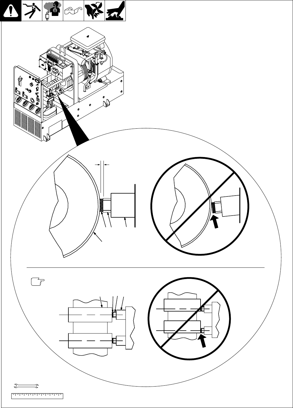
B. Adjusting Brush Position
Stop
engine.
After installing brushes, adjust
brush
position as follows:
1
Brush Holder
2 Brass Sleeve
3 Brush
4
Slip Ring
Loosen brush holder bracket
mounting
hardware. Move bracket
until brass sleeves are positioned
as
shown. T
ighten hardware.
Reinstall side panels and cover
.
If
operation is still not okay
, have a
qualified machine shop turn and
polish
slip rings.
Ref. ST-800 698-A / Ref. ST-800 677-B
T
ools Needed:
3/8, 1/2 in
2
4
1
Center
brushes on slip
rings.
Correct Brush Position
T
op V
iew
Side V
iew
Incorrect Brush Position
1234
3/32 in
(2.4 mm)
Correct
Brush Position
Incorrect
Brush Position
3
TM-428 Page 32
Miller Legend
6-16. Checking Unit Output After Servicing
Ref. ST-800 698-A / ST-800 249
Check engine speeds, and adjust
if necessary (see Section 8-5).
11
15 V
AC 100 Hz Receptacle
RC4
With no load applied and engine
running at weld rpm, there should
be 128 to 132 volts ac present at
RC4.
2 Slider
3 Resistor
R4
YStop engine before adjust-
ing
R4
If necessary, adjust slider on R4
until
128 to
132 volts ac is obtained
at RC4. Do not exceed 132 volts
ac.
4DC
W
eld Output T
erminals
Turn
Fine Amperage control R1 to
max.
With no load applied and en
-
gine running at weld rpm, there
should
be 70
to 72 volts dc present
at
dc weld terminals.
5 Resistor R2
YStop engine before adjust-
ing
R2
If
correct voltage is not present, ad
-
just slider on R2 until correct volt-
age is obtained at dc weld termi-
nals.
Do not exceed 72 volts dc.
Stop engine. Allow engine to
cool,
and
then complete pre-operational
checks
in table.
Reinstall cover and side panels.
T
ools Needed:
2
3
5
2
1
4
Pre-Operational Checks
Wipe engine surfaces clean.
Check labels; replace labels that are unreadable or damaged.
Check and correct any fluid leaks.
Clean weld output and battery terminals.
T
ighten connections.
Clean outside of entire unit.
Check fuel and oil (see Section 2-4).
TM-428 Page 33
Miller Legend
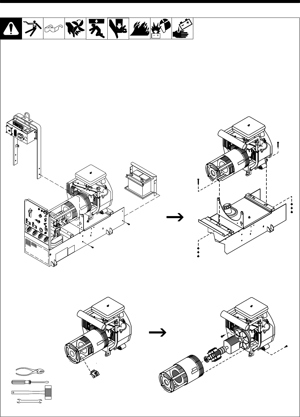
SECTION 7 – DISASSEMBLY AND REASSEMBLY
7-1. Disassembly Of Unit
Use Section 6-1 to determine if
trouble
is
in rotor
, stator
, engine or
a combination of these compo-
nents.
Remove sheet metal panels from
unit. Disconnect negative (–) bat-
tery cable from battery. Remove
spark plugs. Mark and disconnect
all
stator leads.
YDo not damage rotor or sta-
tor
during this procedure.
Use hoist and lifting strap to re-
move the engine/generator as-
sembly.
ST-800 710-A
T
ools Needed:
3/8, 7/16, 1/2, 9/16 in
TM-428 Page 34
Miller Legend
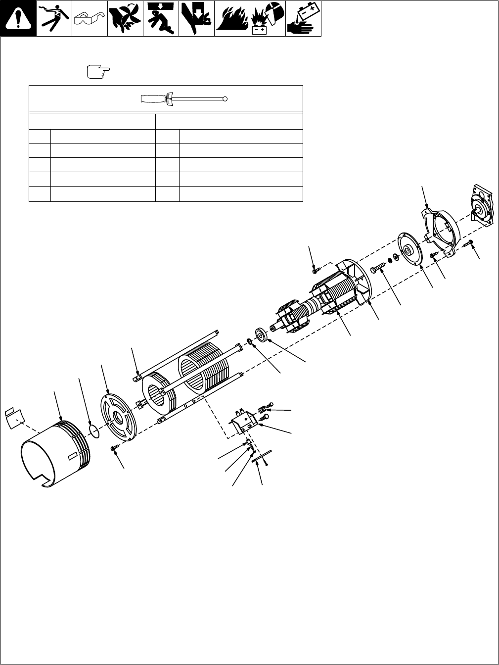
7-2. Disassembly Of Generator
ST-115 942-F
YDo
not
damage stator or rotor wind
-
ings
during this procedure.
Disassembly
With
engine properly supported with blocks,
remove
hardware securing stator to engine.
Remove
generator parts as needed:
1
Fan Guard
2 O-Ring
3 Endbell
4 Stator Assembly
5
Engine Adapter
6
Fan Rotor Adapter
7
Rotor Fan
8 Rotor
9
Ball Bearing
10
Retaining Ring
11
Integrated Rectifier SR2
12 Brush Holder Bracket
13
Brush Holder Retaining Bar
14
Brush Holder Cap
15 Brush
16
Brush Holder
Reassembly
Reinstall engine and generator parts as
needed
(see torque table).
Reconnect
fuel line, choke cable, and base
ground
cable. Reinstall spark plugs, battery
and tray
, panels, and cover
.
Use cable ties to secure leads in existing
wiring
harnesses
and away from moving or
hot
parts.
Reconnect negative (–) battery cable.
Prior T
o Serial No. KD523655
Ef
fective With Serial No. KD523655
A
15 ft lb (20 N
.m) A
15 ft lb (20 N
.m)
B
30 ft lb (41 N
.m) B
20 ft lb (27 N
.m)
C
25 ft lb (34 N
.m) C
25 ft lb (34 N
.m)
D
15 ft lb (20 N
.m) D
20 ft lb (27 N
.m)
E
15 ft lb (20 N
.m) E
15 ft lb (20 N
.m)
Torques:
Hardware may differ from that shown.
1
2
3
4
5
6
7
8
9
10
11
12
1314
15
16
D
B
A
E
C
TM-428 Page 35
Miller Legend
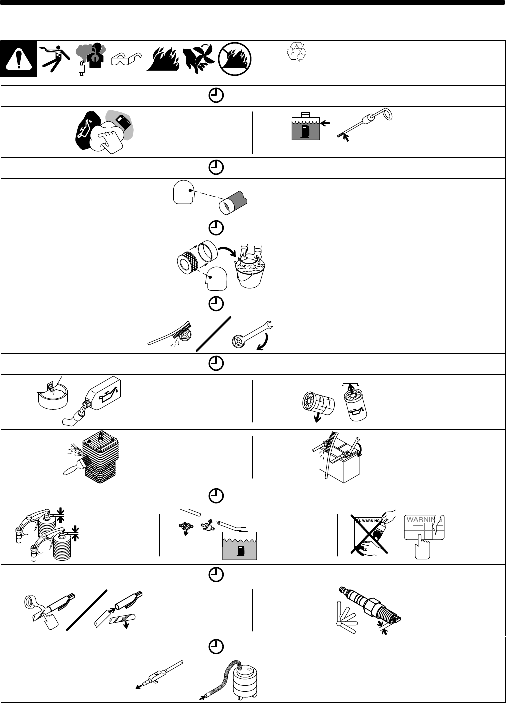
SECTION 8 – MAINTENANCE
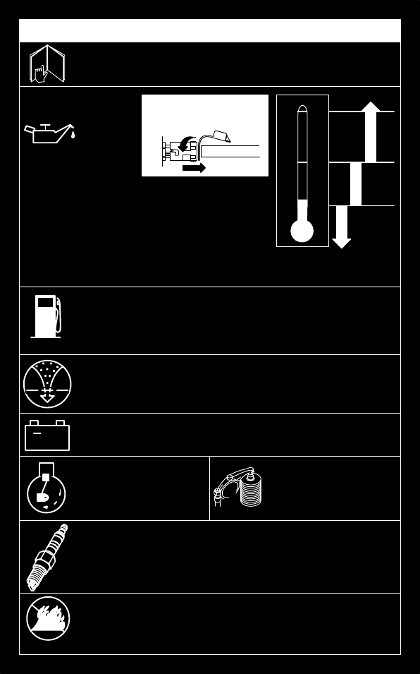
8-1. Routine Maintenance
Recycle
engine
fluids.
Y
Stop engine before maintaining.
.
See also Engine Manual and mainte-
nance
label. Service engine more
often
during
severe conditions.
8 Hours
Wipe
Up
Spills
Check Fluid
Levels.
See Section 2-4
OIL
Full
20 Hours
Check
And
Clean Spark
Arrestor Screen
25 Hours
Clean
And
Check Air
Cleaner
50 Hours
Clean
And
T
ighten W
eld
Terminals
100 Hours
Change
Oil. See
Section 8-4 And
Maintenance
Label
Change Oil Filter
. See
Section 8-4 And
Maintenance Label
Clean And
Tighten
Battery
Connections
Clean Cooling
System,
See Engine
Manual
200 Hours
Replace
Fuel
Filter
.
See Section
8-4.
Replace
Unreadable
Labels
Check
Valve
Clearance
500 Hours
Repair Or Replace
Cracked Cables
Check
Spark
Plugs
1000 Hours
Blow Out Or V
acuum Inside.
During Heavy Service,
Clean Monthly
OR
TM-428 Page 36
Miller Legend
8-2. Maintenance Label
ONAN P218 GAS ENGINE
Check
+
S-176 891
daily.
Optional
Gasoline
°C
+30
+20
+10
0
-10
-20
-30
°F
Spark
Arrestor Inspection And Service
20 operating hours -
.
see Owner’
s Manual
Fuel Grade
Regular or Unleaded
.
. . . . . . . .
Fuel
Filter
MILLER 066 1
13, Onan 149-2206-01,
.
. . . . . . . . .
Fram
G10E1
12 V
olt Battery
BCI Group 58
.
. . . . . . . . . . . . . . . . . . . . . . .
Cranking
Performance at 0
°
F (-18
°C)
430 Amps min.
.
. . .
Engine
RPM – No Load
Power
1650 (50 Hz)
.
. .
1860 (60 Hz)
Weld 3000.
. . . .
Air
Filter Service 100 hours or less – see Owner
’
s Manual
.
. . .
Air
Filter Element
MILLER 064 617, Onan 140-2522
.
. . .
Air
Filter W
rapper
MILLER 065 653, Onan 140-1496
.
. . .
Spark
Plug Gap
0.025 in. (0.6 mm)
.
. . . .
Spark
Plug
Champion RS17YX Preferred or
.
. . . . . . . .
RS14YC
Use
only resistor spark plugs and wires.
0
+40
+100
Recommended Oil
API Service Classification.
. .
SF, SG, SF/CC, SG/CE
Oil & Filter
Change .
. . . . . . . . .
dirty conditions
25 hours or less.
. .
normal conditions
100
hours
.
Oil
Filter
MILLER 065 251, Onan 122-0645
.
. . . . . . . . . . .
Oil Capacity
1.5 qt (1.4 L) or 1.75 qt (1.6 L) with filter change
.
. . . . . . .
Valve
Clearance – Cold
In.
0.005 in (0.13 mm)
.
. .
Ex. 0.013
in (0.33 mm)
.
.
See
Engine Manual for complete engine care. Give engine
Specification and Serial Number when ordering parts.
10W
5W-30
30
Push And
T
o Drain Oil:
Pull
1/2 in. ID Hose
Turn CCW
TM-428 Page 37
Miller Legend
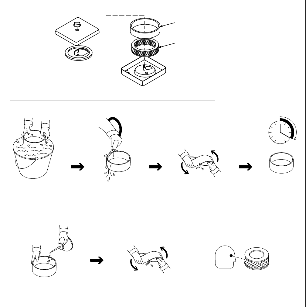
8-3. Servicing Air Cleaner
aircleaner3 1/96 – ST-156 852 / S-0759
YDo not run engine without
air cleaner or with dirty ele-
ment.
Stop
engine.
1 Precleaner
Wash precleaner with soap and
water
solution.
Allow precleaner to
air
dry completely
.
Spread 1 tablespoon SAE 30 oil
evenly into precleaner. Squeeze
out excess oil.
2 Element
Replace element if dirty or oily
.
oil
1
2
TM-428 Page 38
Miller Legend
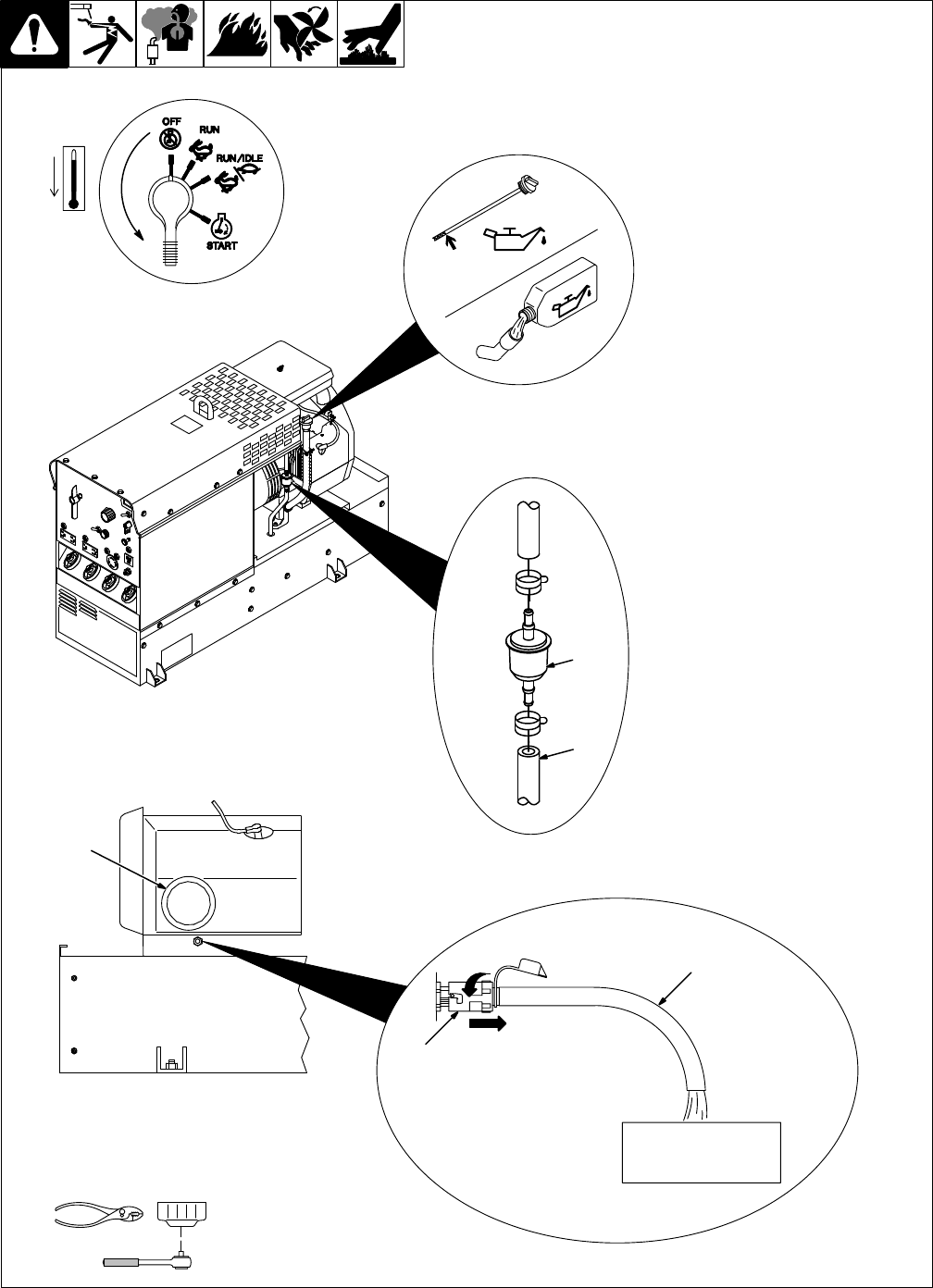
8-4. Changing Engine Oil, Oil Filter, And Fuel Filter
ST-140 091-E / ST-144 840-C Ref. ST-168 046 / ST-800 395 / S-0842
Stop
engine and allow to cool.
1
Oil Drain V
alve
2
1/2 ID x 12 in Hose
3
Oil Filter
Change engine oil and filter ac-
cording
to engine owner
’
s manual.
YClose valve and valve cap
before adding oil and run-
ning
engine.
Fill crankcase with new oil to full
mark
on dipstick
(see Section 8-2).
4 Fuel
Filter
5
Fuel Line
Replace line if cracked or worn.
Install new filter. Wipe up any
spilled
fuel.
Start engine, and check for fuel
leaks.
Stop engine, tighten connections
as necessary
, and wipe up fuel.
T
ools Needed:
1
2
3
4
5
Full
TM-428 Page 39
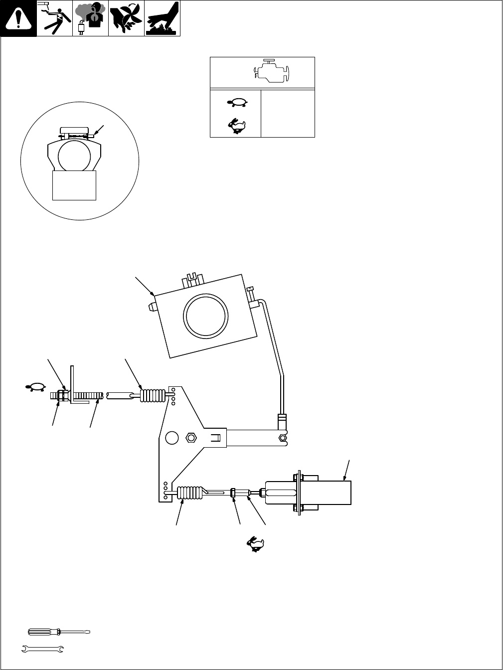
Miller Legend
After tuning engine, check engine
speeds with a tachometer. See
table for proper no load speeds. If
necessary, adjust speeds as fol-
lows:
Start engine, and place Engine
Control
switch
in Run/Idle position.
Turn Fine Amperage control to
100.
1 Carburetor
2 Throttle
Solenoid
Power/Idle Speed Adjustment
3
Power/Idle Speed Rod
4 Lock Nut
5
Adjustment Nut
Loosen
lock nut and rotate adjust
-
ment nut until engine runs at pow
-
er/idle speed. T
ighten lock nut.
W
eld Speed Adjustment
Place
Engine Control
switch in Run
position.
6 Lock
Nut
Loosen nut.
7 Hex Swivel
Turn swivel until engine runs at
weld
speed. T
ighten lock nut.
8W
eld Speed Governor Spring
9
Power/Idle Speed Governor
Spring
If a spring becomes loose or dis-
connected,
reattach as shown.
8-5. Adjusting Engine Speed
Tools
Needed:
1860 rpm
(Power/Idle)
3000 rpm
(Weld)
3/8 in,
8, 1
1 mm
ST-116 049-C
Rear V
iew
T
op V
iew
2
3
4
59
1
8
67
2
TM-428 Page 40
Miller Legend
8-6. Overload Protection
Stop
engine.
1
Circuit Breaker CB4 (Internal
– Not Shown)
CB4 protects the unit from over-
load due to an obstructed throttle
solenoid. If CB4 opens, engine
speed drops to power/idle rpm for
about
10 seconds before
automati
-
cally
resetting.
If CB4 continues to open, check
throttle solenoid TS1 and throttle
linkage.
2 Fuse
F1 (See Parts List For
Rating)
F1 protects the exciter excitation
winding
from overload.
Replace open fuse and reinstall
panel
before operating unit.
If
F1 continues to
open, check inte
-
grated
rectifier SR2 and rotor
.
T
ools Needed:
3/8 in
2
ST-152 264-A
Stop
engine and allow to cool.
1 Spark Arrestor Screen
Clean and inspect screen. Re-
place
spark arrestor if screen wires
are
broken or missing.
8-7. Inspecting And Cleaning Optional Spark Arrestor
Tools
Needed:
1/4 in
ST-140 091-E / ST-801 206 / Ref. ST-168 046
1

TM-428 Page 41
Miller Legend
SECTION 9 – ELECTRICAL DIAGRAMS
.
The
circuits in this manual can be used for troubleshooting, but there
might be minor circuit differences from your machine. Use circuit inside
machine
case or contact factory for actual circuit, if needed.
The following is a list of all diagrams for models covered by this manual. T
o order a copy, proceed as follows:
1
Know unit Model and Serial or Style Number
.
2
Use this list to find diagram number
.
3
Include your F
AX number or mailing address with your request.
4 FAX T
echnical Publications Department at 414-735-401
1 or call 414-735-4356.
Model Serial Or Style Number Circuit
Diagram Wiring
Diagram Main Reason
For Change
Miller
Legend Without Re
-
mote Control
JH2421
14 thru JH300533
SC-1
14 477-A
D-1
17 651
♦♦
JH300534 thru JJ420470
C-1
17 626-B
♦♦
D-123 101
♦♦
Changed PC1 and S1, add
-
ed D5
JJ420471 thru JK713331 C-123 087-B
♦♦
D-130 651-A
♦♦
Added D6
JK713332 thru KA780043
SC-130 929
♦♦
D-130 651-A
♦♦
Removed S1
KA780044 thru KA870083
C-135 624
♦♦
D-135 628
♦♦
Removed F2
KA870084 thru KD346697
C-137 000-A
♦♦
D-136 855-D
♦♦
Added S1
KD346698 thru KD438828
C-157 770
♦♦
D-157 767-A
♦♦
Added PC4, PC5
KD438829 thru KD548029
C-162 148
♦♦
D-162 146
♦♦
Added stator lead 33
KD548030 thru KE604175
C-166 823
♦♦
D-166 822
♦♦
Hourmeter standard
KE604176 thru KE629033
C-167 423
♦♦
D-167 422
♦♦
Changed PC2
KE629034 and following
SC-168 053-A SD-168 051-B
Added CB5, CB7, D8, GFCI
Miller Legend With Re
-
mote Control
JH2421
14 thru JH300533
SC-1
15 947-A
JH300534 thru JJ420470
C-1
18 207-A
♦♦
Changed PC1 and S1, add
-
ed D5
JJ420471 thru JK713331 C-123 088-B
♦♦
Added D6
JK713332 thru KA780043 C-130 928
♦♦
Removed S1
KA780044 thru KA870083
C-135 801
♦♦
Removed F2
KA870084 thru KD346697
C-137 003-B
♦♦
Added S1
KD346698 thru KD438828
C-157 764
♦♦
Added PC4, PC5
KD438829 thru KE604175
C-162 147
♦♦
Added stator lead 33
KE604176 thru KE629033
C-167 402
♦♦
Hourmeter standard,
changed PC2
KE629034 and following
SC-168 054-A
Added CB5, CB7, D8, GFCI
Circuit Board PC1
JH2421
14 thru JH300533
SB-1
13 710
Circuit Board PC2
JH2421
14 thru KE604175
B-049 506-C
♦♦
KE604176 and following
SB-160 891
Circuit Board PC3
♦JH2421
14 thru KA840709
B-1
15 891-A
♦♦
KA840710 and following
SB-136 249
Circuit Board PC4
KD346698 and following
SA-148 024-A
Circuit Board PC5
♦
KD346698 and following
SB-156 027
♦Optional
♦♦ Not
included in this manual
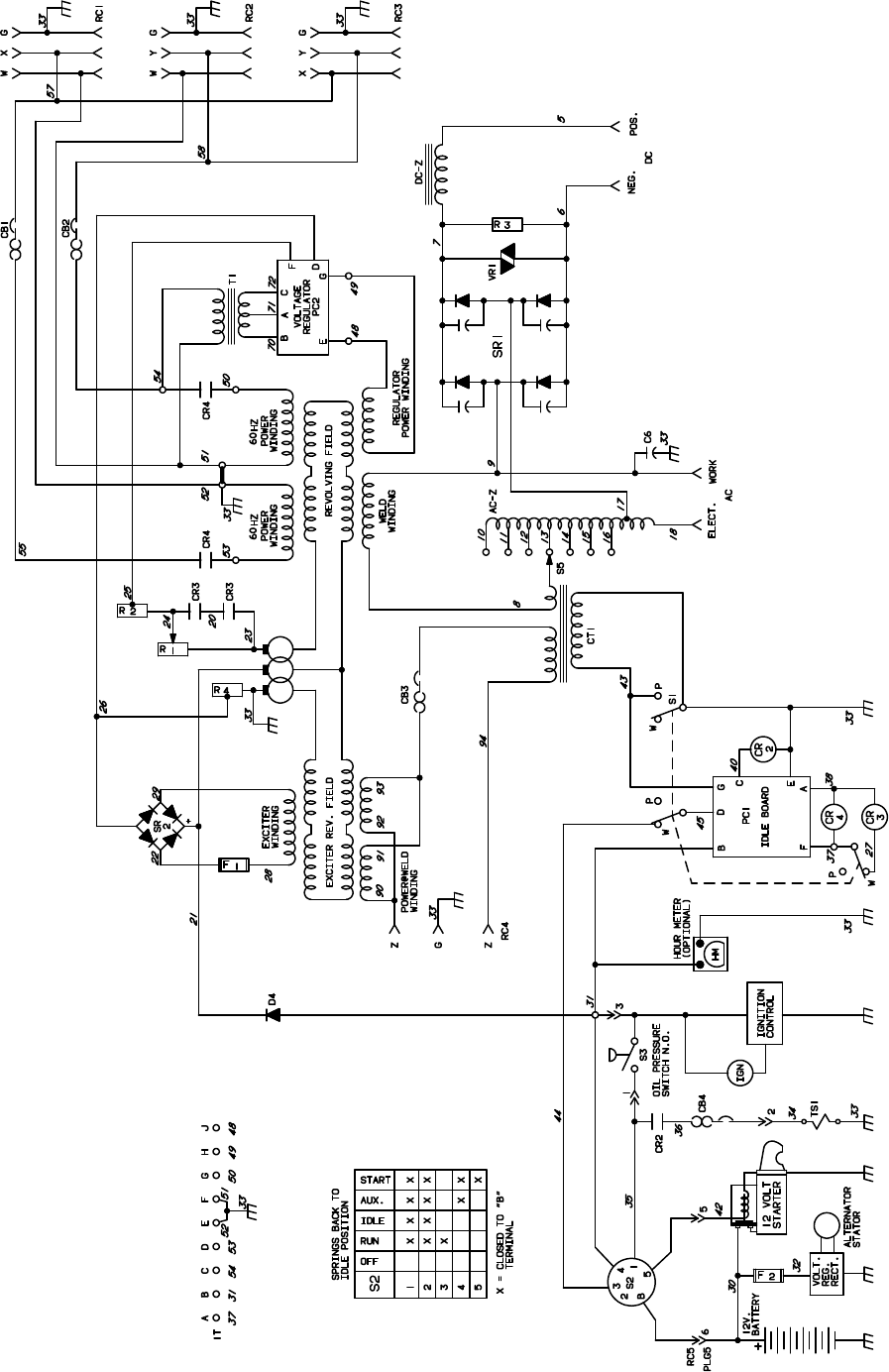
TM-428 Page 42
Miller Legend
SC-114 477-A
Figure 9-1. Circuit Diagram For Miller Legend Without Remote Control
Effective With Serial No. JH242114 Thru JH300533
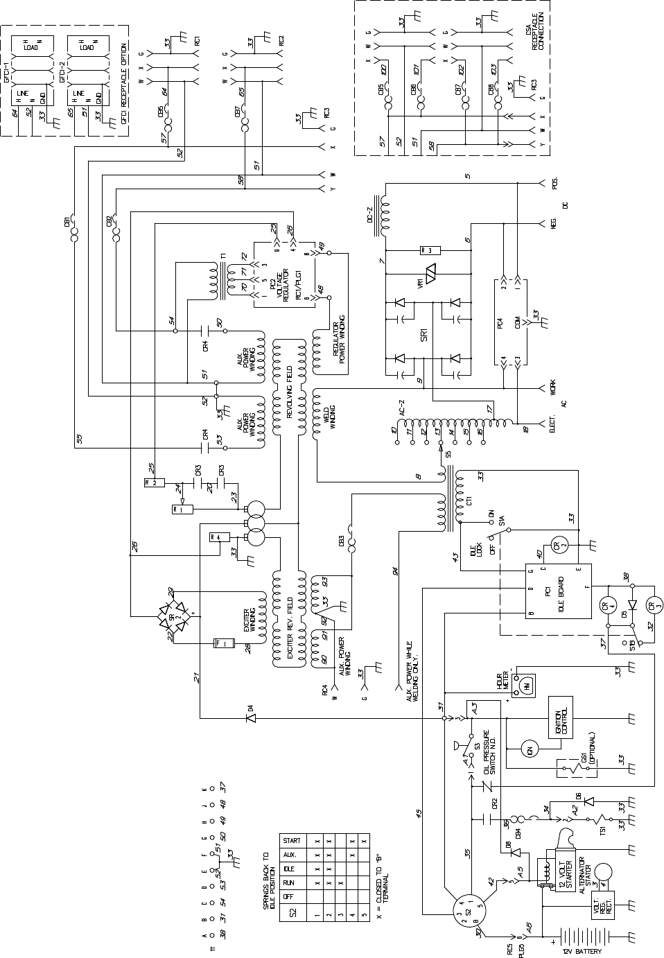
TM-428 Page 43
Miller Legend
SC-168 053-A
Figure 9-2. Circuit Diagram For Miller Legend Without Remote Control
Effective With Serial No. KE629034 And Following
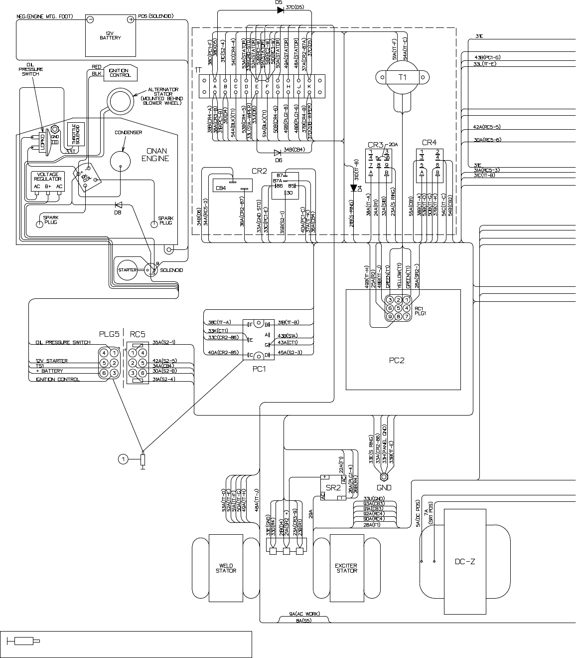
TM-428 Page 44
Miller Legend
Coat
terminals with dielectric grade, nonconductive,
electric grease (MILLER Part No. 146 557) or equivalent.
Figure 9-3.
W
iring Diagram For Miller Legend Without Remote Control
Effective With Serial No. KE629034 And Following
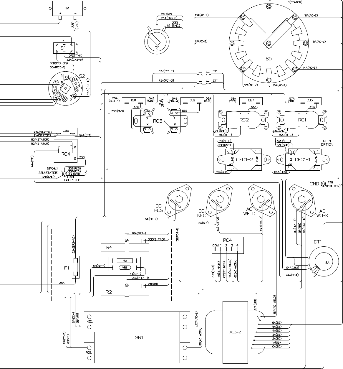
TM-428 Page 45
Miller Legend
SD-168 051-B
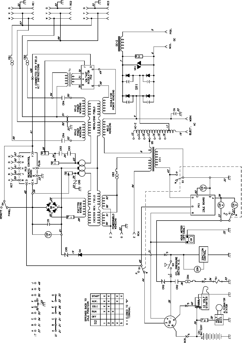
TM-428 Page 46
Miller Legend
SC-115 947-A
Figure 9-4. Circuit Diagram For Miller Legend With Remote Control
Effective With Serial No. JH242114 Thru JH300533
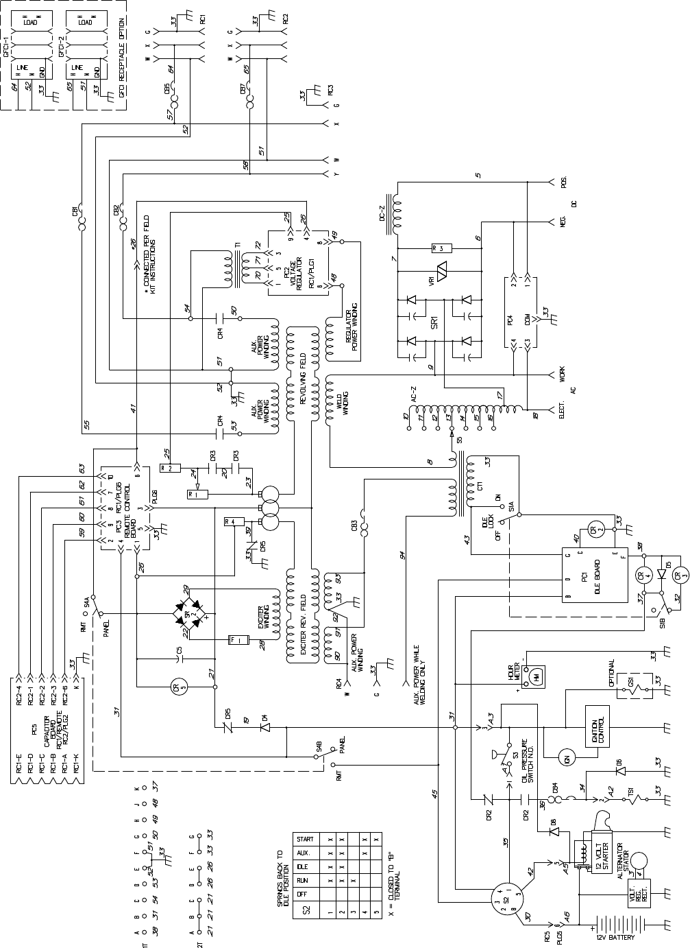
TM-428 Page 47
Miller Legend
SC-168 054-A
Figure 9-5. Circuit Diagram For Miller Legend With Remote Control
Effective With Serial No. KE629034 And Following
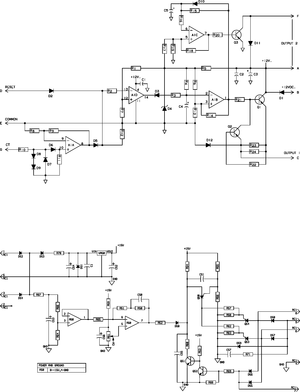
TM-428 Page 48
Miller Legend
SB-113 710
Figure 9-6. Circuit Diagram For Idle Control Board PC1
Effective With Serial No. JH242114 Thru JH300533
SB-160 891
Figure 9-7. Circuit Diagram For Voltage Regulator Board PC2
Effective With Serial No. KE604176 And Following
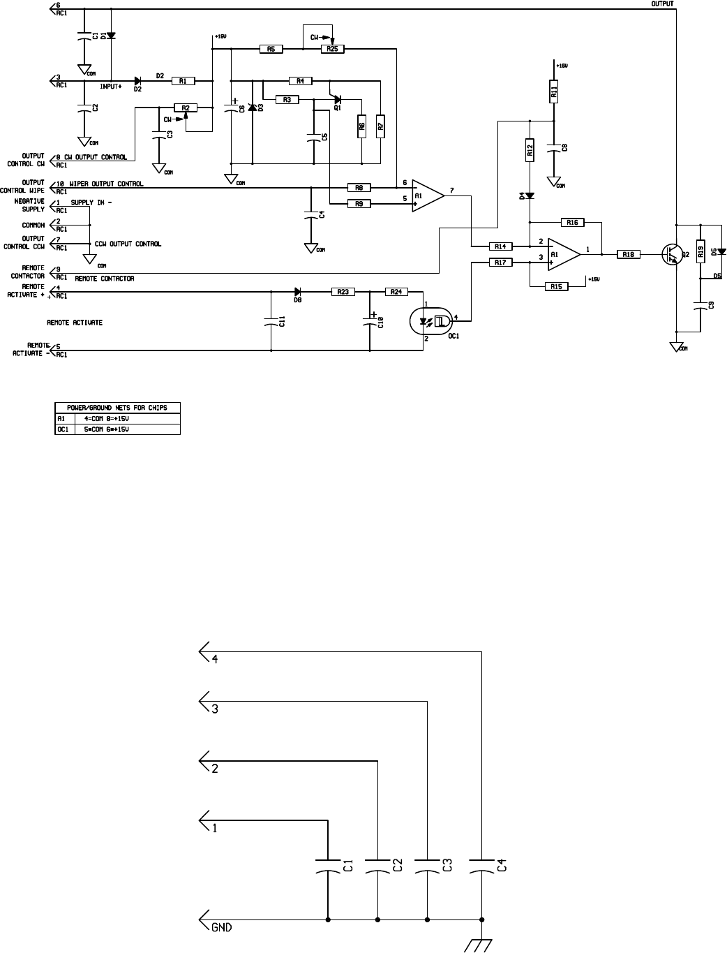
TM-428 Page 49
Miller Legend
SB-136 249
POSITIVE
SUPPLY+
OUTPUT
Figure 9-8. Circuit Diagram For Optional Remote Control Board PC3
Effective With Serial No. KA840710 And Following
SB-148 024-A
Figure 9-9. Circuit Diagram For HF Filter Board PC4
Effective With Serial No. KD346698 And Following
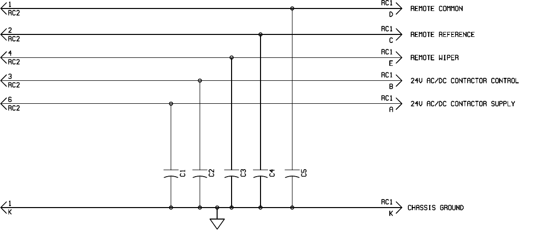
TM-428 Page 50
Miller Legend
SB-156 027
Figure 9-10. Circuit Diagram For Optional Capacitor Board PC5
Effective With Serial No. KD346698 And Following
February 1996 Form: TM-428
Effective With Serial No. JH242114
SECTION 10 – PARTS LIST
TM-428 Page 51
Miller Legend
Miller Legend
(Formerly The Legend AEAD-200LE)
CC AC/DC Welding Generator For SMAW, GMAW, GTAW Welding
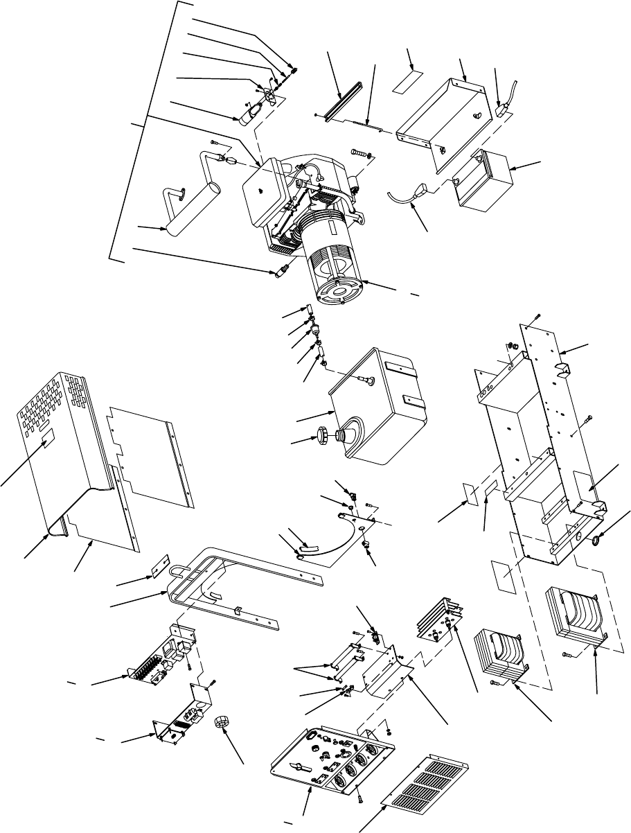
TM-428 Page 52
Miller Legend
Figure 10-5
Figure 10-1. Main Assembly
19
20 21
22 23 24 25 26
1
2
34
5
6
7
89
10 11 27
28
31
32
35
36
38
39
40
41
42
43 45 46 47
48
49
29
37
44
51
50
12 13
30
14 15 16 17 18
33
34
Figure 10-2
Figure 10-3
Figure 10-6

TM-428 Page 53
Miller Legend
Description Quantity
Part
No.
Dia.
Mkgs.
Item
No.
Figure 10-1. Main Assembly
1 ++042 132 REMOTE CONTROL, (Figure 10-6) (Prior to JK713332) 1.
. .
. . . . . . . . . . . . . . . . . . . . . . . . . . . .
1 ++042 383 REMOTE CONTROL, (Figure 10-6) (Eff w/JK713332) 1.
. .
. . . . . . . . . . . . . . . . . . . . . . . . . . . . . .
2 Figure 10-5 CONTROL
P
ANEL, w/components 1.
. .
. . . . . . . . . . . . . . . . . . . . . . . . . . . . . . . . . . . . . . . . . . . . . . .
3 113 302 UPRIGHT, base (Prior to KA780148) 1.
. .
. . . . . . . . . . . . . . . . . . . . . . . . . . . . . . . . . . . . . . . . . . . . . . . .
3 129 384 UPRIGHT, base (Eff w/KA780148 thru KA892304) 1.
. .
. . . . . . . . . . . . . . . . . . . . . . . . . . . . . . . . . . . .
3 136 057 UPRIGHT, base (Eff w/KA892305 and on) 1.
. .
. . . . . . . . . . . . . . . . . . . . . . . . . . . . . . . . . . . . . . . . . . . .
4 107 342
SEAL, lift eye
1.
. .
. . . . . . . . . . . . . . . . . . . . . . . . . . . . . . . . . . . . . . . . . . . . . . . . . . . . . . . . . . . . . . . . . . . . .
5 113 303 P
ANEL, side
2.
. .
. . . . . . . . . . . . . . . . . . . . . . . . . . . . . . . . . . . . . . . . . . . . . . . . . . . . . . . . . . . . . . . . . . . . .
6 +113 304 COVER, top (Prior to JJ365634) 1.
. .
. . . . . . . . . . . . . . . . . . . . . . . . . . . . . . . . . . . . . . . . . . . . . . . . . . .
6 +114 557 COVER, top (Eff w/JJ365634 thru KF812088) 1.
. .
. . . . . . . . . . . . . . . . . . . . . . . . . . . . . . . . . . . . . . .
6 +173 209 COVER, top (Eff w/KF812089) 1.
. .
. . . . . . . . . . . . . . . . . . . . . . . . . . . . . . . . . . . . . . . . . . . . . . . . . . . .
120 304 BLANK, snap-in nyl .250mtg hole (Eff w/JJ365634 thru KB133271) 2.
. . . . . . . . . . . . . . . . . . .
. . . . . . . .
143 397 BLANK, snap-in nyl .312mtg hole (Eff w/KB133272 thru KF812088) 2.
. . . . . . . . . . . . . . . . . . .
. . . . . . .
7 108 487 LABEL, warning falling equipment etc 1.
. .
. . . . . . . . . . . . . . . . . . . . . . . . . . . . . . . . . . . . . . . . . . . . . . .
8 113 439 PANEL, rear lower (Prior to KA780148) 1.
. .
. . . . . . . . . . . . . . . . . . . . . . . . . . . . . . . . . . . . . . . . . . . . . .
8 128 789 PANEL, rear lower (Eff w/KA780148 thru KA892304) 1.
. .
. . . . . . . . . . . . . . . . . . . . . . . . . . . . . . . . . .
8 136 059 PANEL, rear lower (Eff w/KA892305 and on) 1.
. .
. . . . . . . . . . . . . . . . . . . . . . . . . . . . . . . . . . . . . . . . .
9 095 970 STRIP, nprn wsl eng firewall 18 in 2.
. .
. . . . . . . . . . . . . . . . . . . . . . . . . . . . . . . . . . . . . . . . . . . . . . . . . . .
10 088 731 BUSHING, snap-in nyl .375 ID 1.
. .
. . . . . . . . . . . . . . . . . . . . . . . . . . . . . . . . . . . . . . . . . . . . . . . . . . . . . .
11 PLG5 HOUSING, (part of engine wiring harness).
. .
. . . . . . . . . . . . . . . . . . .
113 248 TANK, fuel (Prior to KA780148) (consisting of) 1.
. . . . . . . . . . . . . . . . . . .
. . . . . . . . . . . . . . . . . . . . . . . . . .
015 603 CAP, tank fuel 1.
. . . . . . . . . . . . . . . . . . .
. . . . . . . . . . . . . . . . . . . . . . . . . . . . . . . . . . . . . . . . . . . . . . . . . . . . . .
107 345 NECK, tank fuel 1.
. . . . . . . . . . . . . . . . . . .
. . . . . . . . . . . . . . . . . . . . . . . . . . . . . . . . . . . . . . . . . . . . . . . . . . . . .
113 685 TUBE, pick up fuel 1.
. . . . . . . . . . . . . . . . . . .
. . . . . . . . . . . . . . . . . . . . . . . . . . . . . . . . . . . . . . . . . . . . . . . . . .
010 863 CLAMP, hose 2 1/16-3 clamp dia (Prior to KA780148) 2.
. . . . . . . . . . . . . . . . . . .
. . . . . . . . . . . . . . . . . . .
107 346 HOSE, fuel tank (Prior to KA780148) 1.
. . . . . . . . . . . . . . . . . . .
. . . . . . . . . . . . . . . . . . . . . . . . . . . . . . . . . .
107 324 BRACKET, support pipe filler (Prior to KA780148) 1.
. . . . . . . . . . . . . . . . . . .
. . . . . . . . . . . . . . . . . . . . . . .
107 343 GROMMET, rubber neck filler fuel (Prior to KA780148) 1.
. . . . . . . . . . . . . . . . . . .
. . . . . . . . . . . . . . . . . .
113 486 COVER, fuel tank (Prior to KA780148) 1.
. . . . . . . . . . . . . . . . . . .
. . . . . . . . . . . . . . . . . . . . . . . . . . . . . . . . .
113 392 HOLD DOWN, fuel tank (Prior to KA780148) 1.
. . . . . . . . . . . . . . . . . . .
. . . . . . . . . . . . . . . . . . . . . . . . . . .
113 294 SUPPORT, center mtg engine (Prior to KA780148) 1.
. . . . . . . . . . . . . . . . . . .
. . . . . . . . . . . . . . . . . . . . . .
12 147 601 CAP, tank screw-on w/vent 1.
. .
. . . . . . . . . . . . . . . . . . . . . . . . . . . . . . . . . . . . . . . . . . . . . . . . . . . . . . . . .
13 130 123 TANK, fuel 7.5gal (Eff w/KA780148 thru KG037343) 1.
. .
. . . . . . . . . . . . . . . . . . . . . . . . . . . . . . . . . . .
13 177 606 TANK, fuel 7.5gal (Eff w/KG037344 and on) 1.
. .
. . . . . . . . . . . . . . . . . . . . . . . . . . . . . . . . . . . . . . . . . .
14 145 976 HOSE, nprn SAE .250 ID 1.
. .
. . . . . . . . . . . . . . . . . . . . . . . . . . . . . . . . . . . . . . . . . . . . . . . . . . . . . . . . . .
15 084 173 CLAMP, hose .460–.545clp dia 2.
. .
. . . . . . . . . . . . . . . . . . . . . . . . . . . . . . . . . . . . . . . . . . . . . . . . . . . . .
16 066 113 FILTER, fuel inline .250 (included w/engine) 1.
. .
. . . . . . . . . . . . . . . . . . . . . . . . . . . . . . . . . . . . . . . . . .
17 CLAMP, hose .460–.545clp dia (included w/engine) 2.
. .
. . . . . . . . . . . . . . . . . . . . . . . . . . . . . . . . . . . . . . . . . . .
18 HOSE, nprn SAE .250 ID (included w/engine) (order by ft) 1ft.
. .
. . . . . . . . . . . . . . . . . . . . . . . . . . . . . . . . . . . . .
19 135 627 ENGINE, gas elect start (Prior to KG037344) (consisting of) 1.
. .
. . . . . . . . . . . . . . . . . . . . . . . . . . . .
19 178 479 ENGINE, gas elect start (Eff w/KG037344) (consisting of) 1.
. .
. . . . . . . . . . . . . . . . . . . . . . . . . . . . . .
113 251 FITTING, pipe brs cap .375NPT (Prior to KF933389) 1.
. . . . . . . . . . . . . . . . . . .
. . . . . . . . . . . . . . . . . . . .
113 250 FITTING, pipe galv nipple L .375NPT (Prior to KF933389) 1.
. . . . . . . . . . . . . . . . . . .
. . . . . . . . . . . . . . . .
20 165 271 VALVE, oil drain (Eff w/KF933389) 1.
. .
. . . . . . . . . . . . . . . . . . . . . . . . . . . . . . . . . . . . . . . . . . . . . . . . . .
21 107 297 MUFFLER, exhaust engine (Prior to KF926822) 1.
. .
. . . . . . . . . . . . . . . . . . . . . . . . . . . . . . . . . . . . . .
21 164 353 MUFFLER, exhaust (Eff w/KF926822) 1.
. .
. . . . . . . . . . . . . . . . . . . . . . . . . . . . . . . . . . . . . . . . . . . . . . .
22 106 977
SOLENOID, 12VDC 20A
1.
. .
. . . . . . . . . . . . . . . . . . . . . . . . . . . . . . . . . . . . . . . . . . . . . . . . . . . . . . . . . . .
23 113 563 BRACKET, mtg solenoid (Prior to JK595850) 1.
. .
. . . . . . . . . . . . . . . . . . . . . . . . . . . . . . . . . . . . . . . . .
23 128 534 BRACKET, mtg solenoid(Eff w/JK595850) 1.
. .
. . . . . . . . . . . . . . . . . . . . . . . . . . . . . . . . . . . . . . . . . . . .
24 128 869
LINKAGE KIT
, (Prior to JJ404117) 1.
. .
. . . . . . . . . . . . . . . . . . . . . . . . . . . . . . . . . . . . . . . . . . . . . . . . . . .
24 128 431 SWIVEL, in-line .250-28 (Eff w/JJ404117) 1.
. .
. . . . . . . . . . . . . . . . . . . . . . . . . . . . . . . . . . . . . . . . . . . .
25 128 533 LINK, throttle (Eff w/JJ404117) 1.
. .
. . . . . . . . . . . . . . . . . . . . . . . . . . . . . . . . . . . . . . . . . . . . . . . . . . . . . .
26 064 646 SPRING, high speed 1.
. .
. . . . . . . . . . . . . . . . . . . . . . . . . . . . . . . . . . . . . . . . . . . . . . . . . . . . . . . . . . . . . .
137 046 TUNE-UP & FILTER KIT, (consisting of) 1.
. . . . . . . . . . . . . . . . . . .
. . . . . . . . . . . . . . . . . . . . . . . . . . . . . . . .
064 617 ELEMENT, air cleaner 1.
. . . . . . . . . . . . . . . . . . .
. . . . . . . . . . . . . . . . . . . . . . . . . . . . . . . . . . . . . . . . . . . . . . .
065 251 OIL FILTER 1.
. . . . . . . . . . . . . . . . . . .
. . . . . . . . . . . . . . . . . . . . . . . . . . . . . . . . . . . . . . . . . . . . . . . . . . . . . . . .
121 652 FILTER/CLAMPS, fuel 1.
. . . . . . . . . . . . . . . . . . .
. . . . . . . . . . . . . . . . . . . . . . . . . . . . . . . . . . . . . . . . . . . . . . .
065 709 SP
ARK PLUG
2.
. . . . . . . . . . . . . . . . . . .
. . . . . . . . . . . . . . . . . . . . . . . . . . . . . . . . . . . . . . . . . . . . . . . . . . . . . .

TM-428 Page 54
Miller Legend
Description Quantity
Part
No.
Dia.
Mkgs.
Item
No.
Figure 10-1. Main Assembly (Continued)
27 107 308 HOLD DOWN, bat (Prior to KB113874) 1.
. .
. . . . . . . . . . . . . . . . . . . . . . . . . . . . . . . . . . . . . . . . . . . . . .
27 146 697 HOLD DOWN, bat (Ef
f w/KB1
13874 thru KF959176) 1.
. .
. . . . . . . . . . . . . . . . . . . . . . . . . . . . . . . . . .
27 165 631 HOLD DOWN, bat (Eff w/KF959177 and on) 1.
. .
. . . . . . . . . . . . . . . . . . . . . . . . . . . . . . . . . . . . . . . . . .
010 493 BUSHING, snap-in nyl .625 ID x .875mtg hole (Prior to KA780148) 2.
. . . . . . . . . . . . . . . . . . .
. . . . . . . .
28 165 630 BOLT, J stl .250–20 x 6.125 (Eff w/KF959177) 1.
. .
. . . . . . . . . . . . . . . . . . . . . . . . . . . . . . . . . . . . . . . .
29 168 385 LABEL, warning battery explosion 1.
. .
. . . . . . . . . . . . . . . . . . . . . . . . . . . . . . . . . . . . . . . . . . . . . . . . . . .
115 511 BRACKET, support cover (Prior to KF812089) 2.
. . . . . . . . . . . . . . . . . . .
. . . . . . . . . . . . . . . . . . . . . . . . . .
30 107 270 DOOR, access battery (Prior to KF959177) 1.
. .
. . . . . . . . . . . . . . . . . . . . . . . . . . . . . . . . . . . . . . . . . .
30 175 887 DOOR, access battery (Eff w/KF959177) 1.
. .
. . . . . . . . . . . . . . . . . . . . . . . . . . . . . . . . . . . . . . . . . . . . .
31 088 577 CABLE, bat pos (Prior to KF959177) (consisting of) 1.
. .
. . . . . . . . . . . . . . . . . . . . . . . . . . . . . . . . . . .
31 167 731 CABLE, bat pos (Eff w/KF959177) (included w/engine) (consisting of) 1.
. .
. . . . . . . . . . . . . . . . . . .
071 970 COVER, cable bat post red 1.
. . . . . . . . . . . . . . . . . . .
. . . . . . . . . . . . . . . . . . . . . . . . . . . . . . . . . . . . . . . . . . .
32 BAT 071 678 BATTERY, stor 12V (Prior to KF959177) 1.
. .
. . . . . . . . . . . . . . . . . . . . . . . . . . . . . . . . . . . . . . .
32 BAT 168 037 BATTERY, stor 12V (Eff w/KF959177) 1.
. .
. . . . . . . . . . . . . . . . . . . . . . . . . . . . . . . . . . . . . . . . .
114 923 BOOT, insulator term post red (Prior to KA780148) 1.
. . . . . . . . . . . . . . . . . . .
. . . . . . . . . . . . . . . . . . . . . .
135 571 BOOT, insulator term post red ( Eff w/KA780148 thru KC220663) 1.
. . . . . . . . . . . . . . . . . . .
. . . . . . . . .
108 081 TERMINAL PROTECTOR, battery post mtg 2.
. . . . . . . . . . . . . . . . . . .
. . . . . . . . . . . . . . . . . . . . . . . . . . . .
020 279 CLAMP, stl cushion .750 dia x .281mtg hole (Eff w/KA780148) 2.
. . . . . . . . . . . . . . . . . . .
. . . . . . . . . . . .
33 107 753 CABLE, bat neg (Prior to KA780148) (consisting of) 1.
. .
. . . . . . . . . . . . . . . . . . . . . . . . . . . . . . . . . . .
33 023 641 CABLE, bat neg (Eff w/KA780148 thru KE668694) (consisting of) 1.
. .
. . . . . . . . . . . . . . . . . . . . . . .
33 167 730 CABLE, bat neg (Eff w/KE668695) (consisting of) 1.
. .
. . . . . . . . . . . . . . . . . . . . . . . . . . . . . . . . . . . . .
071 971 COVER, cable bat post blk 1.
. . . . . . . . . . . . . . . . . . .
. . . . . . . . . . . . . . . . . . . . . . . . . . . . . . . . . . . . . . . . . . .
34 Figure 10-2 GENERATOR 1
. . . . . . . . . . . . . . . . . . . . . . . . . . . . . . . . . . . . . . . . . . . . . . . . . . . . . . . . . . . . . . . . . . . .
35 113 298 BASE, (Prior to KA780148) 1.
. .
. . . . . . . . . . . . . . . . . . . . . . . . . . . . . . . . . . . . . . . . . . . . . . . . . . . . . . . . .
35 132 195
BASE, (Ef
f w/KA780148 thru KB113873) 1.
. .
. . . . . . . . . . . . . . . . . . . . . . . . . . . . . . . . . . . . . . . . . . . . .
35 146 710
BASE, (Ef
f w/KB1
13874 and on) 1.
. .
. . . . . . . . . . . . . . . . . . . . . . . . . . . . . . . . . . . . . . . . . . . . . . . . . . . .
36 134 792 LABEL, warning general precautionary engine etc 1.
. .
. . . . . . . . . . . . . . . . . . . . . . . . . . . . . . . . . . . . .
37 057 360 BLANK, snap-in nyl 1.375mtg hole 1.
. .
. . . . . . . . . . . . . . . . . . . . . . . . . . . . . . . . . . . . . . . . . . . . . . . . . .
38 DC-Z 113 450 STABILIZER 1.
. .
. . . . . . . . . . . . . . . . . . . . . . . . . . . . . . . . . . . . . . . . . . . . . . . . . . . . . . . . . . . . . . .
39 AC-Z 113 451 REACTOR 1.
. .
. . . . . . . . . . . . . . . . . . . . . . . . . . . . . . . . . . . . . . . . . . . . . . . . . . . . . . . . . . . . . . . . .
40 SR1 142 503 RECTIFIER, si 1ph 300A 1.
. .
. . . . . . . . . . . . . . . . . . . . . . . . . . . . . . . . . . . . . . . . . . . . . . . . . . . .
41 113 562 BRACKET, mtg resistor (Prior to JK559100) 1.
. .
. . . . . . . . . . . . . . . . . . . . . . . . . . . . . . . . . . . . . . . . . .
41 126 072 BRACKET, mtg-resistor (Eff w/JK559100) 1.
. .
. . . . . . . . . . . . . . . . . . . . . . . . . . . . . . . . . . . . . . . . . . . .
42 114 544 PANEL, front lower 1.
. .
. . . . . . . . . . . . . . . . . . . . . . . . . . . . . . . . . . . . . . . . . . . . . . . . . . . . . . . . . . . . . . . .
43 Figure 10-3 PANEL, front w/components 1.
. .
. . . . . . . . . . . . . . . . . . . . . . . . . . . . . . . . . . . . . . . . . . . . . . . . . . . . .
44 CT1 105 370 TRANSFORMER, current 1.
. .
. . . . . . . . . . . . . . . . . . . . . . . . . . . . . . . . . . . . . . . . . . . . . . . . . . . .
45 012 571 HOLDER, fuse mintr 1.
. .
. . . . . . . . . . . . . . . . . . . . . . . . . . . . . . . . . . . . . . . . . . . . . . . . . . . . . . . . . . . . . .
46 *083 596 FUSE, mintr cer 12A 250V 1.
. .
. . . . . . . . . . . . . . . . . . . . . . . . . . . . . . . . . . . . . . . . . . . . . . . . . . . . . . . .
47 R2,4 008 951 RESISTOR, WW adj 180W 12 ohm 2.
. .
. . . . . . . . . . . . . . . . . . . . . . . . . . . . . . . . . . . . . . . . . . .
48 R3,VR1 046 819 SUPPRESSOR 1.
. .
. . . . . . . . . . . . . . . . . . . . . . . . . . . . . . . . . . . . . . . . . . . . . . . . . . . . . . . . . . .
49 RC5 116 045 HOUSING PLUG & PINS, (consisting of) 1.
. .
. . . . . . . . . . . . . . . . . . . . . . . . . . . . . . . . . . . . . . .
113 633 CONNECTOR, rect univ 084 pin 20-14ga 6.
. . . . . . . . . . . . . . . . . . .
. . . . . . . . . . . . . . . . . . . . . . . . . . . . . .
50 109 994 LABEL, warning engine fuel can cause fire 1.
. .
. . . . . . . . . . . . . . . . . . . . . . . . . . . . . . . . . . . . . . . . . . .
51 013 367 LABEL, warning moving parts can cause serious injury 1.
. .
. . . . . . . . . . . . . . . . . . . . . . . . . . . . . . . .
135 475 KIT, label (Prior to KF959177) 1.
. . . . . . . . . . . . . . . . . . .
. . . . . . . . . . . . . . . . . . . . . . . . . . . . . . . . . . . . . . . .
176 908 KIT, label (Eff w/KF959177) 1.
. . . . . . . . . . . . . . . . . . .
. . . . . . . . . . . . . . . . . . . . . . . . . . . . . . . . . . . . . . . . . .
+When ordering a component originally displaying a precautionary label, the label should also be ordered.
*Recommended Spare Parts.
++Optional Parts
BE SURE T
O PROVIDE MODEL AND SERIAL NUMBER WHEN ORDERING REPLACEMENT P
ARTS.
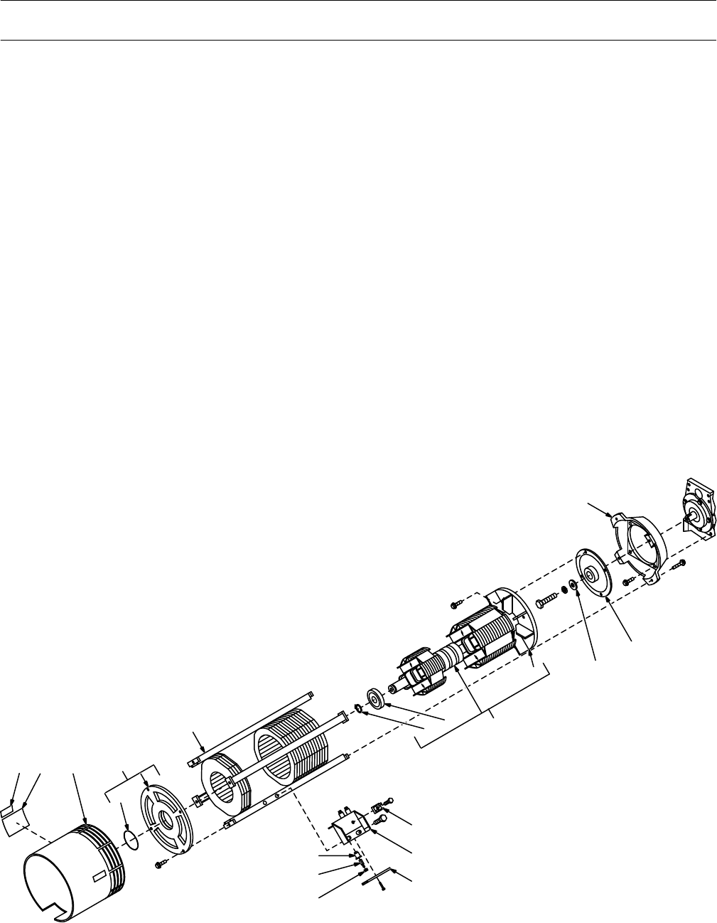
TM-428 Page 55
Miller Legend
Figure 10-2. Generator (Figure 10-1 Item 34)
Description Quantity
Part
No.
Dia.
Mkgs.
Item
No.
1 013 367 LABEL, warning fan 2.
. .
. . . . . . . . . . . . . . . . . . . . . . . . . . . . . . . . . . . . . . . . . . . . . . . . . . . . . . . . . . . . . . .
2 115 500 LABEL, engine maintenance Onan (Prior to KA780148) 1.
. .
. . . . . . . . . . . . . . . . . . . . . . . . . . . . . . .
2 134 092 LABEL, engine maintenance Onan P218 (Eff w/KA780148 thru KF959176) 1.
. .
. . . . . . . . . . . . . .
2 176 891 LABEL, engine maintenance Onan P218 (Eff w/KF959177 and on) 1.
. .
. . . . . . . . . . . . . . . . . . . . . .
3 +113 410 GUARD, fan gen 1.
. .
. . . . . . . . . . . . . . . . . . . . . . . . . . . . . . . . . . . . . . . . . . . . . . . . . . . . . . . . . . . . . . . . .
4 153 297 ENDBELL, gen (consisting of) 1.
. .
. . . . . . . . . . . . . . . . . . . . . . . . . . . . . . . . . . . . . . . . . . . . . . . . . . . . . .
5 143 220 O-RING, 2.859 ID x .139CS 1.
. .
. . . . . . . . . . . . . . . . . . . . . . . . . . . . . . . . . . . . . . . . . . . . . . . . . . . . . . . .
6 165 756 STATOR, gen 60Hz (Prior to KD438829) 1.
. .
. . . . . . . . . . . . . . . . . . . . . . . . . . . . . . . . . . . . . . . . . . . . .
6 162 138 STATOR, gen 60Hz (Eff w/KD438829) 1.
. .
. . . . . . . . . . . . . . . . . . . . . . . . . . . . . . . . . . . . . . . . . . . . . . .
6 165 755 STATOR, gen 50Hz (Prior to KD438829) 1.
. .
. . . . . . . . . . . . . . . . . . . . . . . . . . . . . . . . . . . . . . . . . . . . .
6 162 141 STATOR, gen 50Hz (Eff w/KD438829) 1.
. .
. . . . . . . . . . . . . . . . . . . . . . . . . . . . . . . . . . . . . . . . . . . . . . .
7 017 702
ADAPTER, engine
1.
. .
. . . . . . . . . . . . . . . . . . . . . . . . . . . . . . . . . . . . . . . . . . . . . . . . . . . . . . . . . . . . . . . .
003 455 KEY, woodruff .250 x .750 SAE No. 91 (part of engine) (Prior to KA780148) 1.
. . . . . . . . . . . . . . . .
. . .
8 021 934 ADAPTER, fan rotor (Prior to KA780148) 1.
. .
. . . . . . . . . . . . . . . . . . . . . . . . . . . . . . . . . . . . . . . . . . . .
8 134 981 ADAPTER, fan rotor (Eff w/KA780148) 1.
. .
. . . . . . . . . . . . . . . . . . . . . . . . . . . . . . . . . . . . . . . . . . . . . .
9 008 917 WASHER, flat stl .343 ID x 2 (part of engine) 1.
. .
. . . . . . . . . . . . . . . . . . . . . . . . . . . . . . . . . . . . . . . . .
10 049 286 ROT
OR ASSEMBL
Y, gen (consisting of) 1.
. .
. . . . . . . . . . . . . . . . . . . . . . . . . . . . . . . . . . . . . . . . . . . . .
11 017 624 FAN, rotor gen 1.
. .
. . . . . . . . . . . . . . . . . . . . . . . . . . . . . . . . . . . . . . . . . . . . . . . . . . . . . . . . . . . . . . . . . . . .
12 053 390 BEARING, ball rdl sgl row 1.37 1.
. .
. . . . . . . . . . . . . . . . . . . . . . . . . . . . . . . . . . . . . . . . . . . . . . . . . . . . .
13 024 617 RING, retaining ext 1.272 shaft 1.
. .
. . . . . . . . . . . . . . . . . . . . . . . . . . . . . . . . . . . . . . . . . . . . . . . . . . . . .
602 348 KEY, stl .250 x .250 x .750 1.
. . . . . . . . . . . . . . . .
. . . . . . . . . . . . . . . . . . . . . . . . . . . . . . . . . . . . . . . . . . . . . .
14 SR2 035 704 RECTIFIER, integ 40A 800V 1.
. .
. . . . . . . . . . . . . . . . . . . . . . . . . . . . . . . . . . . . . . . . . . . . . . . . . .
15 007 250 BRACKET, mtg brushholder 1.
. .
. . . . . . . . . . . . . . . . . . . . . . . . . . . . . . . . . . . . . . . . . . . . . . . . . . . . . . . .
16 047 878 BAR, retaining brushholder 1.
. .
. . . . . . . . . . . . . . . . . . . . . . . . . . . . . . . . . . . . . . . . . . . . . . . . . . . . . . . . .
17 161 306 CAP, brushholder 3.
. .
. . . . . . . . . . . . . . . . . . . . . . . . . . . . . . . . . . . . . . . . . . . . . . . . . . . . . . . . . . . . . . . . .
18 *126 984
BRUSH w/SPRING
3.
. .
. . . . . . . . . . . . . . . . . . . . . . . . . . . . . . . . . . . . . . . . . . . . . . . . . . . . . . . . . . . . . .
19 005 614 HOLDER, brush 3.
. .
. . . . . . . . . . . . . . . . . . . . . . . . . . . . . . . . . . . . . . . . . . . . . . . . . . . . . . . . . . . . . . . . . .
ST-115 942-F
12 3
5
4
7
8
9
10
11
12
13
14
15
16
17
18
19
6
Figure 10-2. Generator
+When ordering a component originally displaying a precautionary label, the label should also be ordered.
*Recommended Spare Parts.
BE SURE T
O PROVIDE MODEL AND SERIAL NUMBER WHEN ORDERING REPLACEMENT P
ARTS.
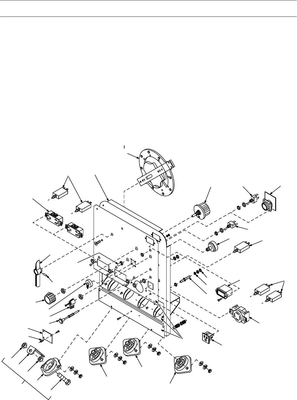
TM-428 Page 56
Miller Legend
Description Quantity
Part
No.
Dia.
Mkgs.
Item
No.
Figure 10-3. Panel, Front w/Components (Figure 10-1 Item 43)
1 RC1,2 604 176 RECEPTACLE, str dx grd 2P3W 15A 125V (Prior to KE629034) 2.
. .
. . . . . . . . . . . . . . . .
073 690 PLUG, str grd armd 2P3W 15A 125V P&S 5266 DF.
. . . . . . . . . . . . . . . . . . .
. . .
1 RC1,2 167 657 RECEPTACLE, str dx grd 2P3W 15A 125V (Eff w/KE629034) 2.
. .
. . . . . . . . . . . . . . . . . .
2 CB1,2 115 427 CIRCUIT BREAKER, man reset 1P 25A 250VAC (Prior to KE629034) 2.
. .
. . . . . . . . . . . .
2 CB5,7 168 057 CIRCUIT BREAKER, man reset 1P 20A 250V
AC (Ef
f w/KE629034) 2.
. .
. . . . . . . . . . . . . .
3 113 315 PANEL, front (Prior to JK713332) 1.
. .
. . . . . . . . . . . . . . . . . . . . . . . . . . . . . . . . . . . . . . . . . . . . . . . . . . .
3 130 352 PANEL, front (Eff w/JK713332 thru KB133271) 1.
. .
. . . . . . . . . . . . . . . . . . . . . . . . . . . . . . . . . . . . . . .
3 143 383 PANEL, front (Eff w/KB133272 thru KF790319) 1.
. .
. . . . . . . . . . . . . . . . . . . . . . . . . . . . . . . . . . . . . . .
3 170 554 PANEL, front (Eff w/KF790320 and on) 1.
. .
. . . . . . . . . . . . . . . . . . . . . . . . . . . . . . . . . . . . . . . . . . . . . .
4 S5 005 563 SWITCH, selector (Figure 10-4) 1.
. .
. . . . . . . . . . . . . . . . . . . . . . . . . . . . . . . . . . . . . . . . . . . . . . . .
5 R1 081 712 RHEOSTAT, WW 100W 30 ohm 1.
. .
. . . . . . . . . . . . . . . . . . . . . . . . . . . . . . . . . . . . . . . . . . . . . . . .
6 S4 ++011 609 SWITCH, tgl SPDT 15A 125VAC (Prior to JK713332) 1.
. .
. . . . . . . . . . . . . . . . . . . . . . . . . . .
6 S4 ++011 611 SWITCH, tgl DPDT 15A 125V (Eff w/JK713332) 1.
. .
. . . . . . . . . . . . . . . . . . . . . . . . . . . . . . . .
7 RC7 035 523 CONNECTOR, circ MS/MET 5skt sz 16S rect MS-3102A-16S-8S.
. .
. . . . . . . . . . .
Amphenol (Prior to JK713332) 1.
. . . . . . . . . . . . . . . . . . . . . . . . . . . . . . . . . . . .
22
23
24
25
26
21
1
23
4
5 6 7
8
910
11
12
14 15
16
17
18
19
20
21
27
28 29
30
31
32
33
34
35
ST-115 943-J
13
Figure 10-4
Figure 10-3. Panel, Front w/Components

TM-428 Page 57
Miller Legend
Description Quantity
Part
No.
Dia.
Mkgs.
Item
No.
Figure 10-3. Panel, Front w/Components (Figure 10-1 Item 43)
(Continued)
039 273 CONNECTOR, circ MS/MET 5 pin sz 16S MS-3106A-16S-8P Amphenol.
. . . . . . . . . . . . . . . . . . .
. . .
039 685 CONNECTOR, circ MS/MET clamp str rlf sz 16-16S AN-3057-8 Amphenol.
. . . . . . . . . . . . . . . . . . .
. . .
7 RC7 ++086 022 CONNECTOR, circ MS/MET 14skt sz 20 MS-3102A-20-27S.
. .
. . . . . . . .
(Eff w/JK713332 thru KD344393) 1.
. . . . . . . . . . . . . . . . . . . . . . . . . . . . . . . . .
109 766 CONNECTOR, circ 14 pin MS sz 20 Amphenol 97-4106A-20-27P.
. . . . . . . . . . . . . . . . . . .
. . .
109 770 CONNECTOR, circ MS pin push-in 16-22ga.
. . . . . . . . . . . . . . . . . . .
. . .
039 734 CONNECTOR, circ MS/MET clamp str rlf sz 20-22S.
. . . . . . . . . . . . . . . . . . .
. . .
Amphenol AN-3057-12
7 PC5 156 025 CIRCUIT CARD, connector/receptacle (Eff w/KD344394) 1.
. .
. . . . . . . . . . . . . . . . . . . . . . . .
C7-11 ++097 749 CAPACITOR, (Eff w/JK713332 thru KD344393) 5.
. . . . . . . . .
. . . . . . . . . . . . . . . . . . . . . . . . . .
8 S1 011 622 SWITCH, tgl 3PDT 15A 125VAC (Prior to JK713332) 1.
. .
. . . . . . . . . . . . . . . . . . . . . . . . . . . . . .
8 S1 011 611 SWITCH, tgl DPDT 15A 125V (Eff w/JK713332) 1.
. .
. . . . . . . . . . . . . . . . . . . . . . . . . . . . . . . . . .
9 S2 172 070 SWITCH, ignition 1.
. .
. . . . . . . . . . . . . . . . . . . . . . . . . . . . . . . . . . . . . . . . . . . . . . . . . . . . . . . . . . . . .
10 CB3 083 432 CIRCUIT BREAKER, man reset 1P 10A 250V 1.
. .
. . . . . . . . . . . . . . . . . . . . . . . . . . . . . . . . . .
11 601 836 NUT, brs hex jam hvy .250-20 3.
. .
. . . . . . . . . . . . . . . . . . . . . . . . . . . . . . . . . . . . . . . . . . . . . . . . . . . . . .
12 010 915 WASHER, flat brs .250 ID x .625 OD 2.
. .
. . . . . . . . . . . . . . . . . . . . . . . . . . . . . . . . . . . . . . . . . . . . . . . .
13 083 030 STUD, brs grd .250-20 x 1.750 1.
. .
. . . . . . . . . . . . . . . . . . . . . . . . . . . . . . . . . . . . . . . . . . . . . . . . . . . . .
14 ♦042 130 METER KIT, (Prior to KD548030) (consisting of) 1.
. .
. . . . . . . . . . . . . . . . . . . . . . . . . . . . . . . . . . . .
HM 032 936 METER, hour 1.
. . . . . . . . . .
. . . . . . . . . . . . . . . . . . . . . . . . . . . . . . . . . . . . . . . . . . . . . . . . . . . . . . . . . . . .
14 145 247 METER, hour 12-24VDC (Eff w/KD548030) 1.
. .
. . . . . . . . . . . . . . . . . . . . . . . . . . . . . . . . . . . . . . . . . .
15 CB1,2 144 474 CIRCUIT BREAKER, man reset 1P 25A 250V
AC (Ef
f w/KE629034) 2.
. .
. . . . . . . . . . . . . .
16 RC3 604 103 RECEPTACLE, str dx grd 2P3W 15A 250V (Prior to JH300534) 1.
. .
. . . . . . . . . . . . . . . . . . .
025 234 PLUG, str grd 2P3W 15A 250V Leviton 5443.
. . . . . . . . . . . . . . . . . . .
. . .
16 RC3 129 067 RECEPTACLE, twlk grd 3P4W 30A 125/250V (Eff w/JH300534) 1.
. .
. . . . . . . . . . . . . . . . . .
088 898 PLUG, twlk grd 3P4W 30A 125/250V.
. . . . . . . . . . . . . . . . . . .
. . .
17 RC4 034 952 RECEPTACLE, str 3P3W 15A 125V 1.
. .
. . . . . . . . . . . . . . . . . . . . . . . . . . . . . . . . . . . . . . . . . . .
073 690 PLUG, str grd armd 2P3W 15A 125V P&S 5266 DF.
. . . . . . . . . . . . . . . . . . .
. . .
18 NAMEPLATE, (order by model & serial number) 1.
. .
. . . . . . . . . . . . . . . . . . . . . . . . . . . . . . . . . . . . . . . . . . . . . .
19 POS 039 047 TERMINAL, pwr output red (consisting of) 1.
. .
. . . . . . . . . . . . . . . . . . . . . . . . . . . . . . . . . . . . . .
20 NEG 039 046 TERMINAL, pwr output black (consisting of) 1.
. .
. . . . . . . . . . . . . . . . . . . . . . . . . . . . . . . . . . . .
21 099 255 TERMINAL, pwr output neutral (consisting of) 2.
. .
. . . . . . . . . . . . . . . . . . . . . . . . . . . . . . . . . . . . . . . .
22 601 976 SCREW, cap stl hex hd .500-13 x 1.500 1.
. .
. . . . . . . . . . . . . . . . . . . . . . . . . . . . . . . . . . . . . . . . . . . . . .
23 039 049 TERMINAL BOARD, red 1.
. .
. . . . . . . . . . . . . . . . . . . . . . . . . . . . . . . . . . . . . . . . . . . . . . . . . . . . . . . . . . .
23 039 045 TERMINAL BOARD, black 1.
. .
. . . . . . . . . . . . . . . . . . . . . . . . . . . . . . . . . . . . . . . . . . . . . . . . . . . . . . . . .
23 039 040 TERMINAL BOARD, neutral 1.
. .
. . . . . . . . . . . . . . . . . . . . . . . . . . . . . . . . . . . . . . . . . . . . . . . . . . . . . . . .
24 601 880 NUT, stl hex jam .500-13 1.
. .
. . . . . . . . . . . . . . . . . . . . . . . . . . . . . . . . . . . . . . . . . . . . . . . . . . . . . . . . . . .
25 039 044 BUS BAR, term bd 1.
. .
. . . . . . . . . . . . . . . . . . . . . . . . . . . . . . . . . . . . . . . . . . . . . . . . . . . . . . . . . . . . . . . .
26 601 879 NUT, stl hex full fnsh .500-13 1.
. .
. . . . . . . . . . . . . . . . . . . . . . . . . . . . . . . . . . . . . . . . . . . . . . . . . . . . . . .
27 073 756 STAND-OFF, No. 6-32 x .625 lg x .250 hex (Eff w/KD344394) 2.
. .
. . . . . . . . . . . . . . . . . . . . . . . . . . .
153 501
HOUSING PLUG & SOCKETS, (Ef
f w/KD344394) (consisting of) 1.
. . . . . . . . . . . . . . . . . . .
. . . . . . . . .
147 995 CONNECTOR, rect univ 039skt 22-18 6.
. . . . . . . . . . . . . . . . . . .
. . . . . . . . . . . . . . . . . . . . . . . . . . . . . . . . .
28 C6 115 109 CAPACITOR, (Prior to KD344394) 1.
. .
. . . . . . . . . . . . . . . . . . . . . . . . . . . . . . . . . . . . . . . . . . . . . .
28 PC4 148 021 CIRCUIT CARD, filter HF (Eff w/KD344394) 1.
. .
. . . . . . . . . . . . . . . . . . . . . . . . . . . . . . . . . . . .
29 111 584 CONTROL, push-pull (Prior to JH283238) 1.
. .
. . . . . . . . . . . . . . . . . . . . . . . . . . . . . . . . . . . . . . . . . . . .
29 116 813 CONTROL, push-pull (Eff w/JH283238) 1.
. .
. . . . . . . . . . . . . . . . . . . . . . . . . . . . . . . . . . . . . . . . . . . . . .
30 119 014
LEVER, switch
1.
. .
. . . . . . . . . . . . . . . . . . . . . . . . . . . . . . . . . . . . . . . . . . . . . . . . . . . . . . . . . . . . . . . . . . .
31 ++108 864 CAP, dust connector 9760-16 (Prior to JK713332) 1.
. .
. . . . . . . . . . . . . . . . . . . . . . . . . . . . . . . . . .
31 ++109 993 CAP, dust connector 9760-20 (Eff w/JK713332) 1.
. .
. . . . . . . . . . . . . . . . . . . . . . . . . . . . . . . . . . . .
32 097 924 KNOB, pointer 1.
. .
. . . . . . . . . . . . . . . . . . . . . . . . . . . . . . . . . . . . . . . . . . . . . . . . . . . . . . . . . . . . . . . . . . . .
33 010 647 PIN, spring cs .156 x 1.250 1.
. .
. . . . . . . . . . . . . . . . . . . . . . . . . . . . . . . . . . . . . . . . . . . . . . . . . . . . . . . . .
34 ++021 385 BOOT, tgl switch lever 1.
. .
. . . . . . . . . . . . . . . . . . . . . . . . . . . . . . . . . . . . . . . . . . . . . . . . . . . . . . . . . .
35 115 493 HANDLE, switch range 1.
. .
. . . . . . . . . . . . . . . . . . . . . . . . . . . . . . . . . . . . . . . . . . . . . . . . . . . . . . . . . . . .
++Part of Remote Control Option
♦Effective w/KD548030 Optional Meter Kit became Standard Equipment.
BE SURE T
O PROVIDE MODEL AND SERIAL NUMBER WHEN ORDERING REPLACEMENT P
ARTS.
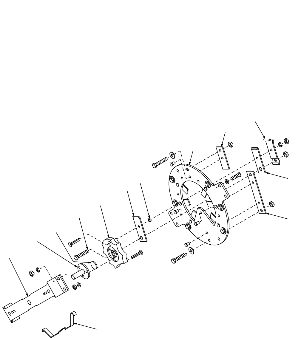
TM-428 Page 58
Miller Legend
Description Quantity
Part
No.
Item
No.
Figure 10-4. Switch, Selector (Figure 10-3 Item 4)
005 563
1 005 562 BRACKET, mtg-switch 1.
. .
. . . . . . . . . . . . . . . . . . . . . . . . . . . . . . . . . . . . . . . . . . . . . . . . . . . . . . . . . . . .
2 005 561 SHAFT, rotor 1.
. .
. . . . . . . . . . . . . . . . . . . . . . . . . . . . . . . . . . . . . . . . . . . . . . . . . . . . . . . . . . . . . . . . . . . .
3 005 564 INSULATOR, screw switch 1.
. .
. . . . . . . . . . . . . . . . . . . . . . . . . . . . . . . . . . . . . . . . . . . . . . . . . . . . . . . .
4 605 276 SCREW, cap stl hex hd .250-20 x 1.250 1.
. .
. . . . . . . . . . . . . . . . . . . . . . . . . . . . . . . . . . . . . . . . . . . .
5 005 559 CONTACT BOARD, movable switch 1.
. .
. . . . . . . . . . . . . . . . . . . . . . . . . . . . . . . . . . . . . . . . . . . . . . .
6 005 560 CONTACT, switch movable 1.
. .
. . . . . . . . . . . . . . . . . . . . . . . . . . . . . . . . . . . . . . . . . . . . . . . . . . . . . . .
7 008 485 SPACER, contact switch 1.
. .
. . . . . . . . . . . . . . . . . . . . . . . . . . . . . . . . . . . . . . . . . . . . . . . . . . . . . . . . . .
8 005 566 CONTACT BOARD, stationary switch 1.
. .
. . . . . . . . . . . . . . . . . . . . . . . . . . . . . . . . . . . . . . . . . . . . . .
9 011 644 CONTACT, stationary switch 7.
. .
. . . . . . . . . . . . . . . . . . . . . . . . . . . . . . . . . . . . . . . . . . . . . . . . . . . . . .
10 052 405 SPRING, pressure contact switch 1.
. .
. . . . . . . . . . . . . . . . . . . . . . . . . . . . . . . . . . . . . . . . . . . . . . . . . .
11 052 404 CONTACT, movable switch 1.
. .
. . . . . . . . . . . . . . . . . . . . . . . . . . . . . . . . . . . . . . . . . . . . . . . . . . . . . . .
12 005 557 BUS BAR, switch range 1.
. .
. . . . . . . . . . . . . . . . . . . . . . . . . . . . . . . . . . . . . . . . . . . . . . . . . . . . . . . . . .
13 005 558 SPRING, selector switch 1.
. .
. . . . . . . . . . . . . . . . . . . . . . . . . . . . . . . . . . . . . . . . . . . . . . . . . . . . . . . . . .
ST-097 264-A
1
2
3
4
5
6
7
8
9
10
11
12
13
Figure 10-4. Switch, Selector
BE SURE T
O PROVIDE MODEL AND SERIAL NUMBER WHEN ORDERING REPLACEMENT P
ARTS.
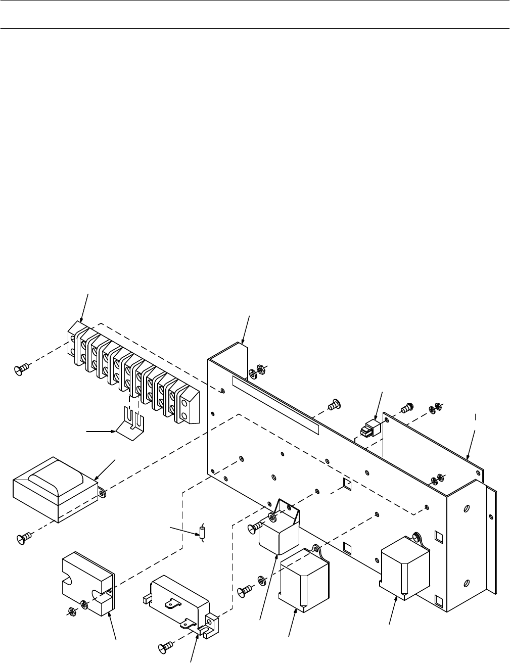
TM-428 Page 59
Miller Legend
Description Quantity
Part
No.
Dia.
Mkgs.
Item
No.
Figure 10-5. Control Panel, w/Components (Figure 10-1 Item 2)
1 1T 038 601 BLOCK, term 30A 9P (Prior to JK713332) 1.
. .
. . . . . . . . . . . . . . . . . . . . . . . . . . . . . . . . . . . . . . . .
1 1T 130 648 BLOCK, term 30A 10P (Eff w/JK713332) 1.
. .
. . . . . . . . . . . . . . . . . . . . . . . . . . . . . . . . . . . . . . . . .
2 113 682 BRACKET, mtg components (Prior to JK713332) 1.
. .
. . . . . . . . . . . . . . . . . . . . . . . . . . . . . . . . . . . . . .
2 130 649 BRACKET, mtg components (Eff w/JK713332) 1.
. .
. . . . . . . . . . . . . . . . . . . . . . . . . . . . . . . . . . . . . . . .
3 083 147 GROMMET, scr No.8/10 4.
. .
. . . . . . . . . . . . . . . . . . . . . . . . . . . . . . . . . . . . . . . . . . . . . . . . . . . . . . . . . . .
4 PC2 049 404 CIRCUIT CARD, regulator 115V (Prior to KE604176) 1.
. .
. . . . . . . . . . . . . . . . . . . . . . . . . . . .
4 PC2 160 888 CIRCUIT CARD, voltage regulator (Eff w/KE604176) (Figure 10-7) 1.
. .
. . . . . . . . . . . . . . . .
PLG1 168 071 CONNECT
OR & SOCKETS, (Ef
f w/KE604176) (consisting of) 1.
. . . . . . . . .
. . . . . . . . . . . . . . . .
114 066 CONNECTOR, rect skt 20-14ga 9.
. . . . . . . . . . . . . . . . . . .
. . . . . . . . . . . . . . . . . . . . . . . . . . . . . . . . . . . . . .
5 CR4 113 247 RELAY, encl 12VDC DPDT 1.
. .
. . . . . . . . . . . . . . . . . . . . . . . . . . . . . . . . . . . . . . . . . . . . . . . . . . .
6 CR3 044 588 RELAY, encl 12VDC 3PDT 1.
. .
. . . . . . . . . . . . . . . . . . . . . . . . . . . . . . . . . . . . . . . . . . . . . . . . . . .
7 CR2 173 069 RELAY, encl 12VDC SPDT 1.
. .
. . . . . . . . . . . . . . . . . . . . . . . . . . . . . . . . . . . . . . . . . . . . . . . . . . .
8 CB4 045 061 CIRCUIT BREAKER, auto reset 24VDC 7A 1.
. .
. . . . . . . . . . . . . . . . . . . . . . . . . . . . . . . . . . . .
9 PC1 113 492 CIRCUIT CARD, weld/idle (Prior to JH300534) 1.
. .
. . . . . . . . . . . . . . . . . . . . . . . . . . . . . . . . .
9 PC1 142 725 MODULE, pull to weld/power delay (Eff w/JH300534) 1.
. .
. . . . . . . . . . . . . . . . . . . . . . . . . . . .
10 D4 059 389 DIODE, rect 3A 1000V SP (Prior to JH300534) 1.
. .
. . . . . . . . . . . . . . . . . . . . . . . . . . . . . . . . . . .
10 D4,5 059 389 DIODE, rect 3A 1000V SP (Eff w/JH300534) 2.
. .
. . . . . . . . . . . . . . . . . . . . . . . . . . . . . . . . . . .
11 T1 116 083 TRANSFORMER, control (Prior to KE604176) 1.
. .
. . . . . . . . . . . . . . . . . . . . . . . . . . . . . . . . . . . .
11 T1 167 404 TRANSFORMER, control (Eff w/KE604176) 1.
. .
. . . . . . . . . . . . . . . . . . . . . . . . . . . . . . . . . . . . . .
12 038 620 LINK, jumper term blk 30A 1.
. .
. . . . . . . . . . . . . . . . . . . . . . . . . . . . . . . . . . . . . . . . . . . . . . . . . . . . . . . . .
D6 117 566 DIODE, rect 6A 600V 1.
. . . . . . . . . .
. . . . . . . . . . . . . . . . . . . . . . . . . . . . . . . . . . . . . . . . . . . . . . . . . . . . .
1
2
3
4
5
6
7
8
9
10
11
12
ST-114 309-B
Figure 10-7
Figure 10-5. Control Panel, w/Components
BE SURE T
O PROVIDE MODEL AND SERIAL NUMBER WHEN ORDERING REPLACEMENT P
ARTS.
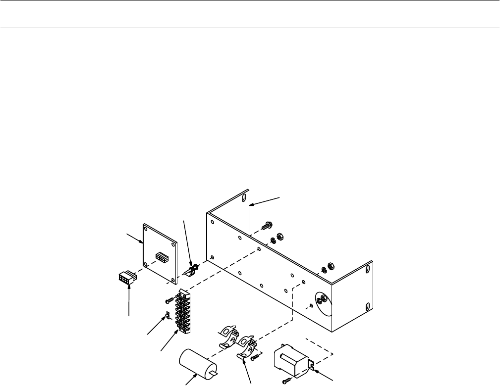
TM-428 Page 60
Miller Legend
Description Quantity
Part
No.
Dia.
Mkgs.
Item
No.
Figure 10-6. Remote Control, Option (Figure 10-1 Item 1)
+042 383
+042 132
1 PC3 136 246
CIRCUIT CARD ASSEMBL
Y, remote control 1.
. .
. . . . . . . . . . . . . . . . . . . . . . . . . . . . . . . . . . .
2 110 375 STAND-OFF SUPPORT, PC card 4.
. .
. . . . . . . . . . . . . . . . . . . . . . . . . . . . . . . . . . . . . . . . . . . . . . . . . . .
3 116 086 BRACKET, mtg remote control (Prior to JK563388) 1.
. .
. . . . . . . . . . . . . . . . . . . . . . . . . . . . . . . . . . . .
3 125 873 BRACKET, mtg remote control (Eff w/JK563388) 1.
. .
. . . . . . . . . . . . . . . . . . . . . . . . . . . . . . . . . . . . . .
4 CR5 052 603 RELAY, encl 110VDC DPDT 1.
. .
. . . . . . . . . . . . . . . . . . . . . . . . . . . . . . . . . . . . . . . . . . . . . . . . . .
5 007 532 CLAMP, capacitor 1.000dia 1.
. .
. . . . . . . . . . . . . . . . . . . . . . . . . . . . . . . . . . . . . . . . . . . . . . . . . . . . . . . . .
6 C5 059 887 CAPACITOR, polyp met film 10uf 220V 1.
. .
. . . . . . . . . . . . . . . . . . . . . . . . . . . . . . . . . . . . . . . . . .
7 2T 116 005 BLOCK, term 10A 7P 1.
. .
. . . . . . . . . . . . . . . . . . . . . . . . . . . . . . . . . . . . . . . . . . . . . . . . . . . . . . . . . .
8 108 023 LINK, jumper term blk 10A 4.
. .
. . . . . . . . . . . . . . . . . . . . . . . . . . . . . . . . . . . . . . . . . . . . . . . . . . . . . . . . .
9 PLG6 115 091 HOUSING PLUG & SOCKETS, (consisting of) 1.
. .
. . . . . . . . . . . . . . . . . . . . . . . . . . . . . . . . . .
113 746 TERMINAL, female 1skt 18-24W 10.
. . . . . . . . . . . . . . . . . . .
. . . . . . . . . . . . . . . . . . . . . . . . . . . . . . . . . . . . . .
1
2
3
4
56
7
8
9
SB-116 028
Figure 10-6. Remote Control, Option
+See Figure 10-3 for additional parts not listed
BE SURE T
O PROVIDE MODEL AND SERIAL NUMBER WHEN ORDERING REPLACEMENT P
ARTS.
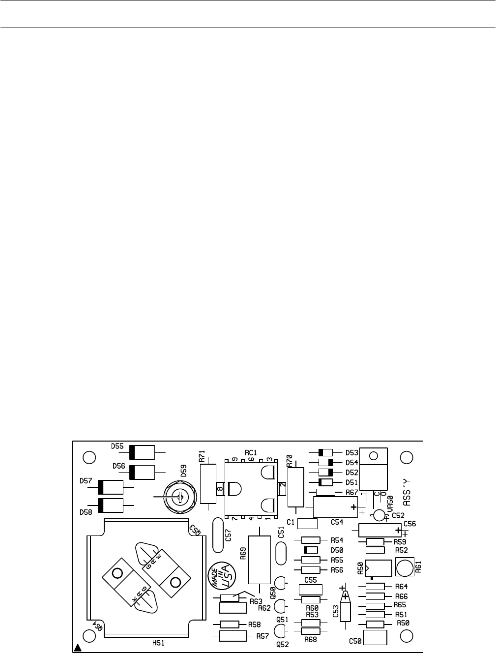
TM-428 Page 61
Miller Legend
Description Quantity
Part
No.
Figure 10-7. Circuit Card, Voltage Regulator (Figure 10-5 Item 4)
Dia.
Mkgs.
PC2 160 888
A50 165 411 IC, linear 2904 1.
. . . . .
. . . . . . . . . . . . . . . . . . . . . . . . . . . . . . . . . . . . . . . . . . . . . . . . . . . . . . . . . . . . . .
C1 003 530 CAPACITOR, cer mono 1uf 50VDC 1.
. . . . . .
. . . . . . . . . . . . . . . . . . . . . . . . . . . . . . . . . . . . . . . . . . .
C50 119 199 CAPACITOR, polye met film 1uf 50V 1.
. . . . .
. . . . . . . . . . . . . . . . . . . . . . . . . . . . . . . . . . . . . . . . . . .
C51 053 992 CAPACITOR, cer disc .001uf 1000VDC 1.
. . . . .
. . . . . . . . . . . . . . . . . . . . . . . . . . . . . . . . . . . . . . . .
C52 000 348 CAPACITOR, tantlm .47uf 35V 1.
. . . . .
. . . . . . . . . . . . . . . . . . . . . . . . . . . . . . . . . . . . . . . . . . . . . . .
C53 005 023 CAPACITOR, tantlm 2.2uf 20V 1.
. . . . .
. . . . . . . . . . . . . . . . . . . . . . . . . . . . . . . . . . . . . . . . . . . . . . .
C54 072 935 CAPACITOR, elctlt 33uf 35VDC 1.
. . . . .
. . . . . . . . . . . . . . . . . . . . . . . . . . . . . . . . . . . . . . . . . . . . . .
C55 137 463 CAPACITOR, polye met film .22uf 100VDC 1.
. . . . .
. . . . . . . . . . . . . . . . . . . . . . . . . . . . . . . . . . . .
C56 072 113 CAPACITOR, tantlm 4.7uf 35VDC 1.
. . . . .
. . . . . . . . . . . . . . . . . . . . . . . . . . . . . . . . . . . . . . . . . . . . .
C57 028 292 CAPACITOR, cer disc .005uf 1000VDC 1.
. . . . .
. . . . . . . . . . . . . . . . . . . . . . . . . . . . . . . . . . . . . . . .
D50 028 351 DIODE, sig 200mA 75V SP 1.
. . . . .
. . . . . . . . . . . . . . . . . . . . . . . . . . . . . . . . . . . . . . . . . . . . . . . . . .
D51 049 641 DIODE, zener 27V 1W 1.
. . . . .
. . . . . . . . . . . . . . . . . . . . . . . . . . . . . . . . . . . . . . . . . . . . . . . . . . . . . .
D52-54 026 202 DIODE, rect 1A 400V SP 3.
. . . .
. . . . . . . . . . . . . . . . . . . . . . . . . . . . . . . . . . . . . . . . . . . . . . . . . .
D55-58 070 250 DIODE, rect 3A 600V 4.
. . . .
. . . . . . . . . . . . . . . . . . . . . . . . . . . . . . . . . . . . . . . . . . . . . . . . . . . . .
D59 030 529 DIODE, rect 22A 600V RP 1.
. . . . .
. . . . . . . . . . . . . . . . . . . . . . . . . . . . . . . . . . . . . . . . . . . . . . . . . . .
Q50 039 355 TRANSISTOR, ujt 15mA 40V 1.
. . . . .
. . . . . . . . . . . . . . . . . . . . . . . . . . . . . . . . . . . . . . . . . . . . . . .
Q51,52 037 200 TRANSISTOR, NPN 200mA 40V 2.
. . . .
. . . . . . . . . . . . . . . . . . . . . . . . . . . . . . . . . . . . . . . . . . .
Q53,54 049 642 THYRIST
OR, SCR 8A 600V
2.
. . . .
. . . . . . . . . . . . . . . . . . . . . . . . . . . . . . . . . . . . . . . . . . . . . . .
R50 094 447 RESISTOR, MF .25W 681K ohm 1.
. . . . .
. . . . . . . . . . . . . . . . . . . . . . . . . . . . . . . . . . . . . . . . . . . . .
R51 044 789 RESISTOR, MF .25W 100K ohm 1.
. . . . .
. . . . . . . . . . . . . . . . . . . . . . . . . . . . . . . . . . . . . . . . . . . . .
R52 035 829 RESISTOR, MF .25W 1.5K ohm 1.
. . . . .
. . . . . . . . . . . . . . . . . . . . . . . . . . . . . . . . . . . . . . . . . . . . . .
R53,54,65 072 559 RESISTOR, MF .25W 22.1K ohm 3.
. .
. . . . . . . . . . . . . . . . . . . . . . . . . . . . . . . . . . . . . . . . . .
R55 115 530 RESISTOR, MF .25W 2.67K ohm 1.
. . . . .
. . . . . . . . . . . . . . . . . . . . . . . . . . . . . . . . . . . . . . . . . . . . . .
R56,64 000 885 RESISTOR, MF .25W 10K ohm 2.
. . . .
. . . . . . . . . . . . . . . . . . . . . . . . . . . . . . . . . . . . . . . . . . . .
R57,62 028 285 RESISTOR, C .5W 100 ohm 2.
. . . .
. . . . . . . . . . . . . . . . . . . . . . . . . . . . . . . . . . . . . . . . . . . . . . .
R58,63 035 823 RESISTOR, MF .25W 100 ohm 2.
. . . .
. . . . . . . . . . . . . . . . . . . . . . . . . . . . . . . . . . . . . . . . . . . . .
R59 072 559 RESISTOR, MF .25W 22.1K ohm 1.
. . . . .
. . . . . . . . . . . . . . . . . . . . . . . . . . . . . . . . . . . . . . . . . . . . .
R60 074 026 RESISTOR, C .25W 150 ohm 1.
. . . . .
. . . . . . . . . . . . . . . . . . . . . . . . . . . . . . . . . . . . . . . . . . . . . . . .
R61 138 301 POTENTIOMETER, cermet trmr 1/T .5W 25K ohm 1.
. . . . .
. . . . . . . . . . . . . . . . . . . . . . . . . . . . . .
R66 093 030 RESISTOR, MF .25W 15K ohm 1.
. . . . .
. . . . . . . . . . . . . . . . . . . . . . . . . . . . . . . . . . . . . . . . . . . . . .
R67 093 032 RESISTOR, MF .25W 26.7K ohm 1.
. . . . .
. . . . . . . . . . . . . . . . . . . . . . . . . . . . . . . . . . . . . . . . . . . . .
R68 108 437 RESISTOR, MF .25W 4.75K ohm 1.
. . . . .
. . . . . . . . . . . . . . . . . . . . . . . . . . . . . . . . . . . . . . . . . . . . .
R69 049 439 RESISTOR, C 2W 47K ohm 1.
. . . . .
. . . . . . . . . . . . . . . . . . . . . . . . . . . . . . . . . . . . . . . . . . . . . . . . . .
R70 074 099 RESISTOR, C 1W 150 ohm 1.
. . . . .
. . . . . . . . . . . . . . . . . . . . . . . . . . . . . . . . . . . . . . . . . . . . . . . . . .
R71 030 707 RESISTOR, C 1W 47 ohm 1.
. . . . .
. . . . . . . . . . . . . . . . . . . . . . . . . . . . . . . . . . . . . . . . . . . . . . . . . . .
RC1 160 892 CONNECTOR, rect 9 pin 3 row rcpt 1.
. . . . .
. . . . . . . . . . . . . . . . . . . . . . . . . . . . . . . . . . . . . . . . . .
VR50 083 772 IC, rgltr 7815 1.
. . . . .
. . . . . . . . . . . . . . . . . . . . . . . . . . . . . . . . . . . . . . . . . . . . . . . . . . . . . . . . . . . . . .
SA-160 889
Figure 10-7. Circuit Card, Voltage Regulator PC2
BE SURE T
O PROVIDE MODEL AND SERIAL NUMBER WHEN ORDERING REPLACEMENT P
ARTS.

Notes

Notes

