Miltope CAP Access Point With Two 802.11abg WLAN Cards User Manual revised manual
Miltope Corporation Access Point With Two 802.11abg WLAN Cards revised manual
UserManual.wiki
>
Miltope
>
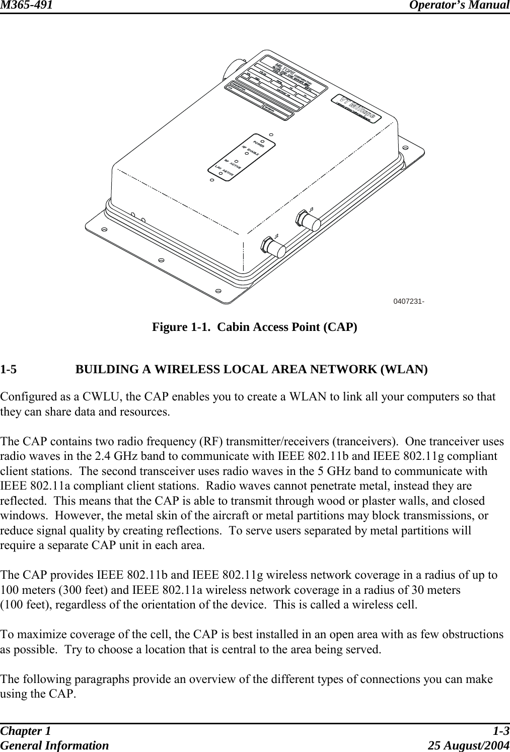
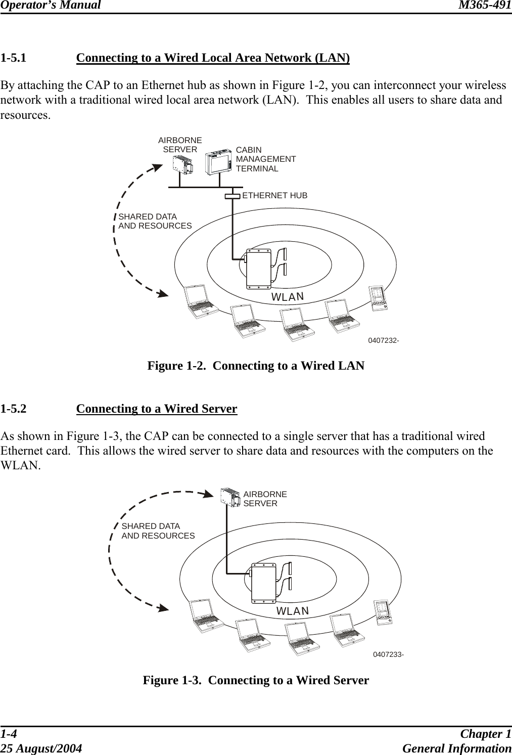
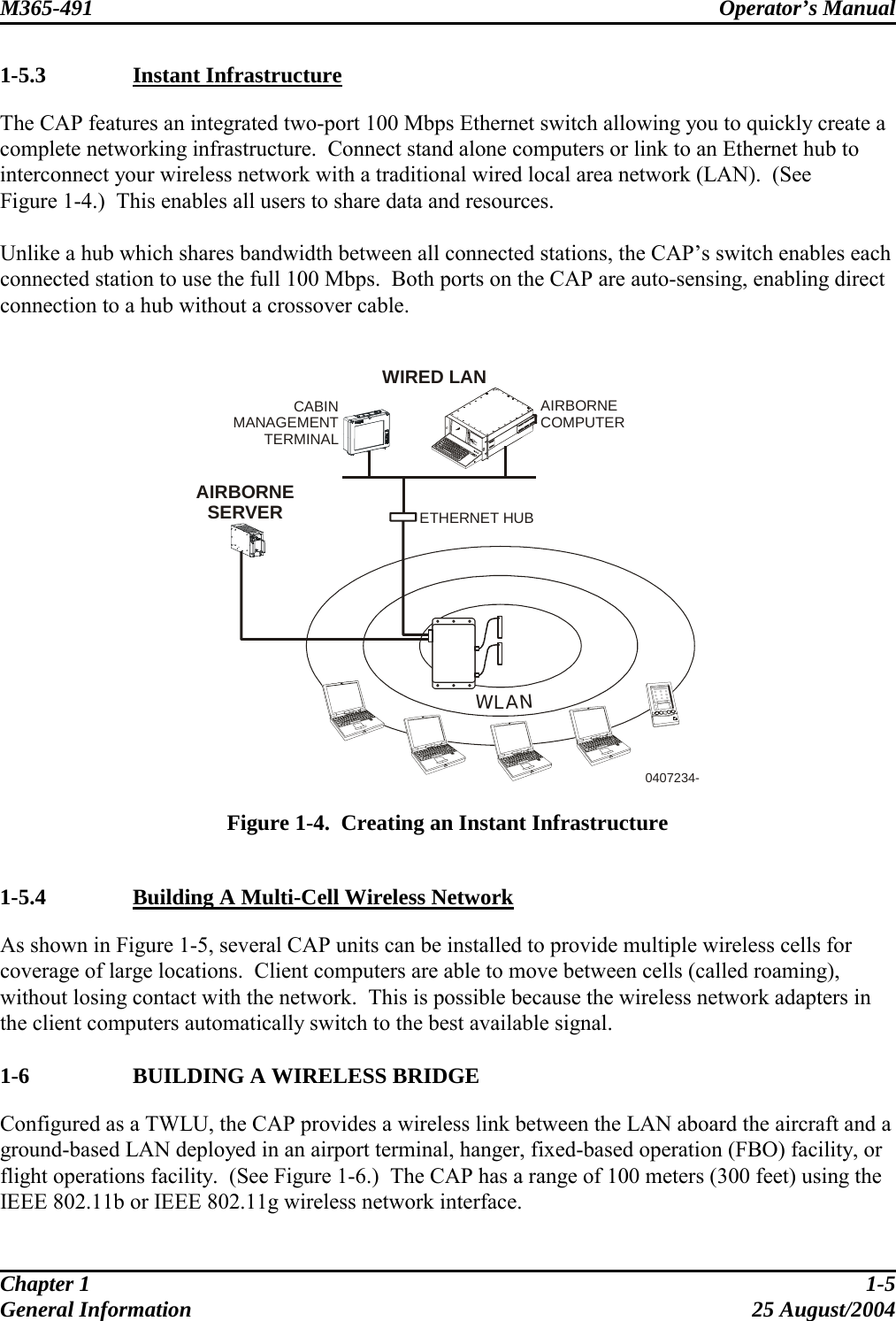
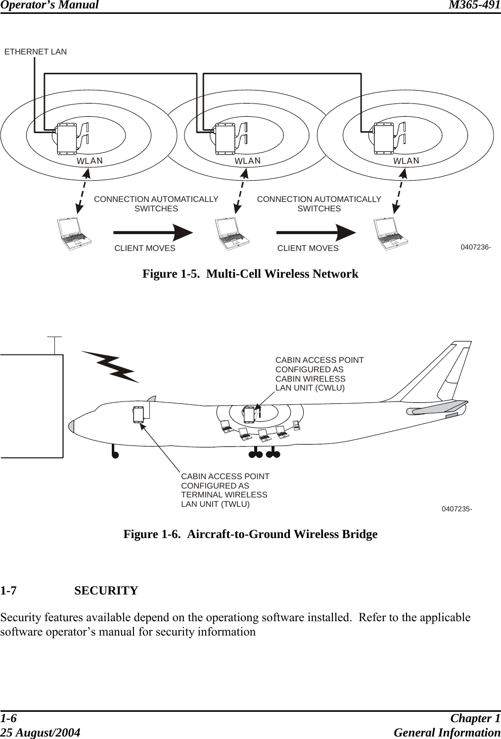
CAP User Manual
revised manual
Navigation menu
Upload a User Manual
Namespaces
Wiki Guide
HTML
PDF
Info
Views
User Manual
Discussion / Help
Navigation