Mimosa Networks 100-00018 Mimosa C5c User Manual
Mimosa Networks, Inc. Mimosa C5c Users Manual
UserManual.wiki
>
Mimosa Networks
>
100 00018 User Manual
Users Manual
Navigation menu
Upload a User Manual
Namespaces
Wiki Guide
HTML
PDF
Info
Views
User Manual
Discussion / Help
Navigation
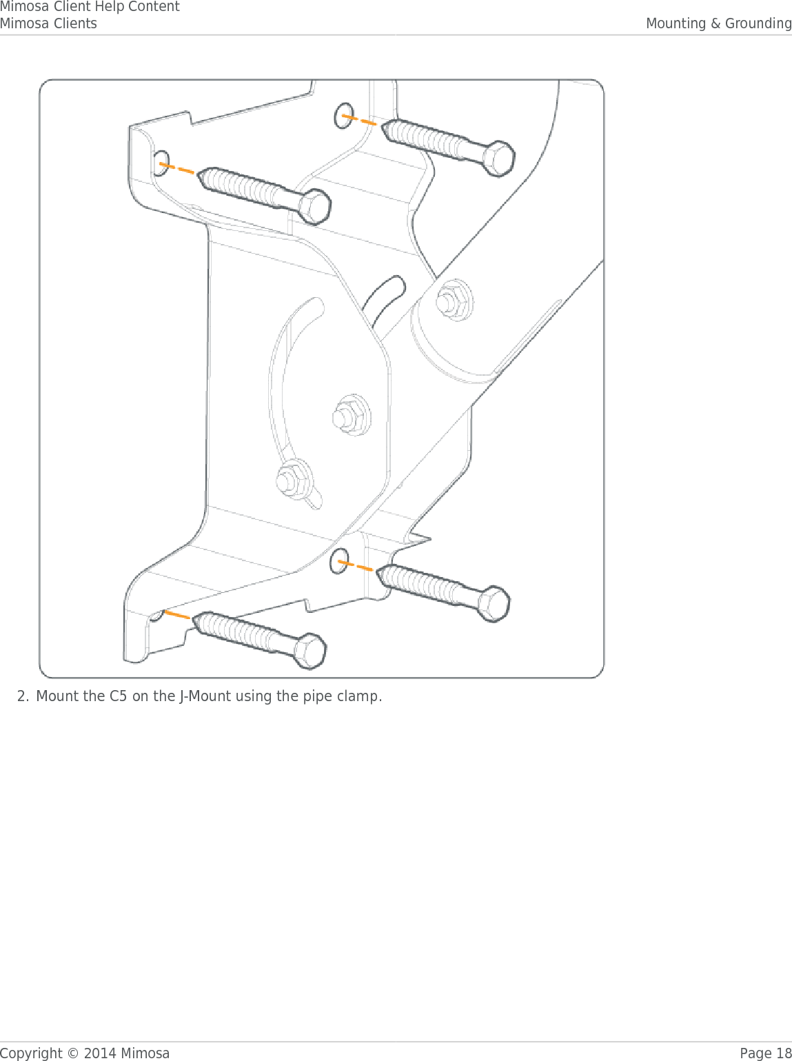
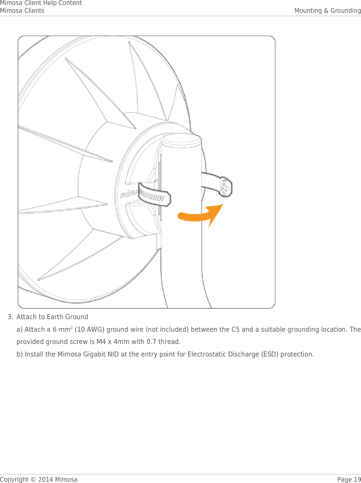
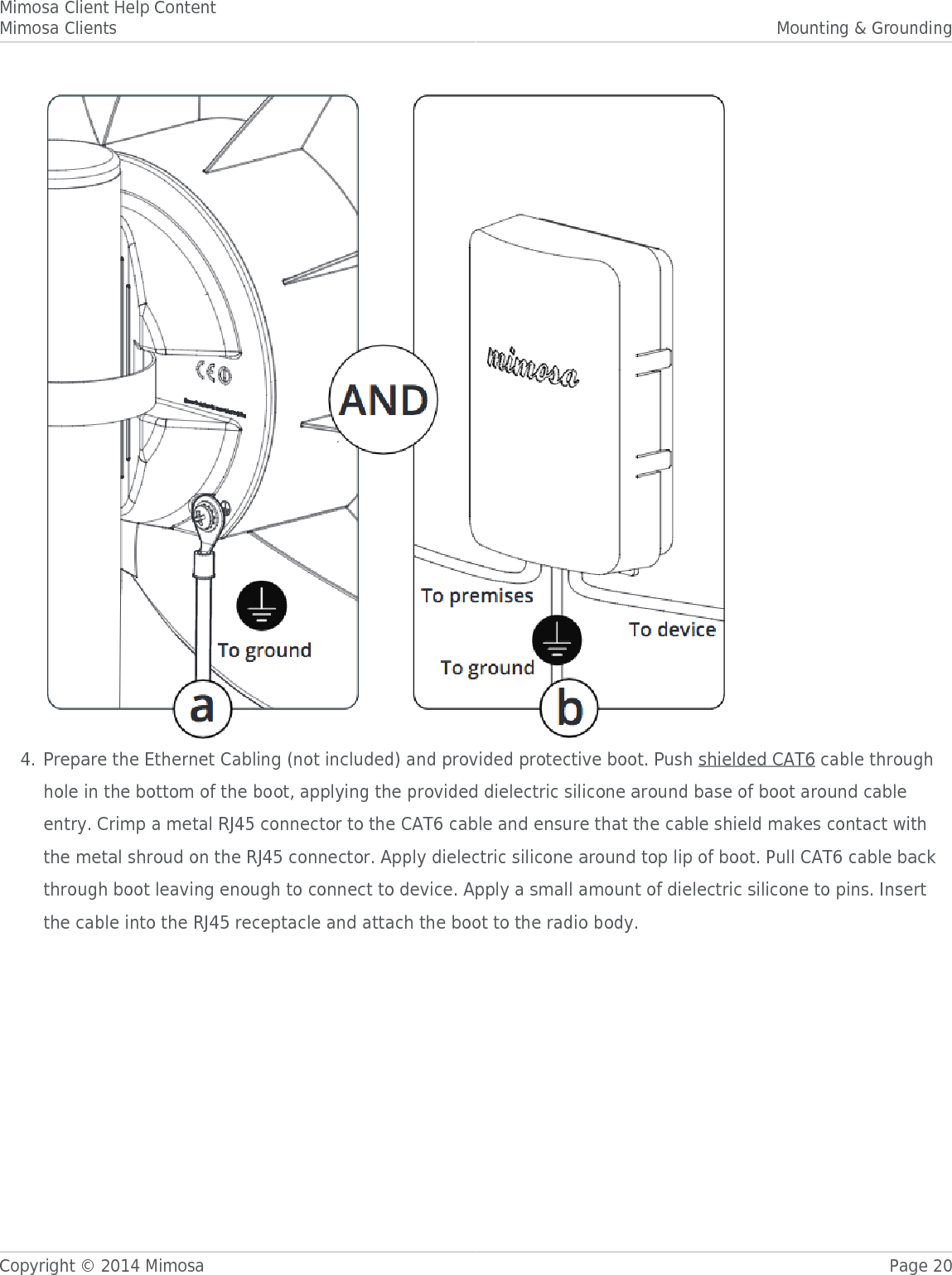
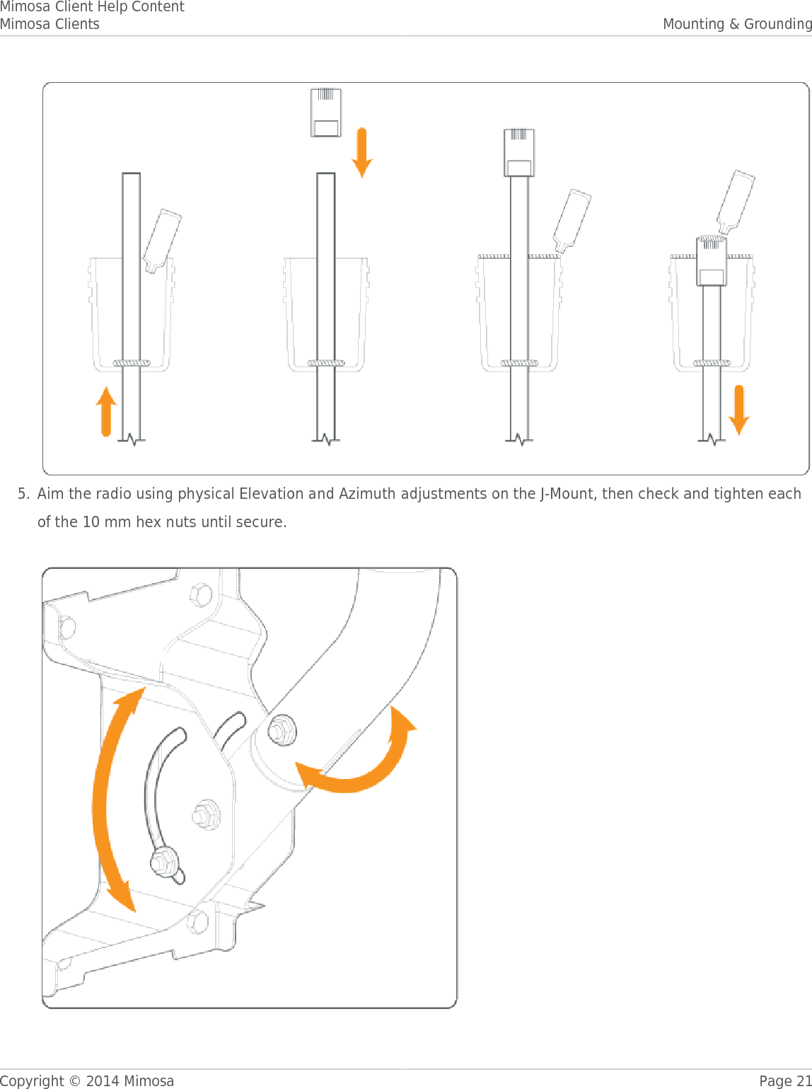

![Mimosa Client Help ContentMimosa Clients GeneralCopyright © 2014 Mimosa Page 58Setting a PasswordEnter the new password in both the New Password and Verify New Password input boxes to validate that they weretyped correctly. To finalize the change, enter the existing password and then save. The default password should bechanged during device configuration to protect your network. New Password - Enter the new password.●Verify New Password - Re-enter the new password (to confirm).●Current Password - Enter the existing password (as a security measure).●The password validation rules are as follows:It must be between 6 to 64 characters.●It can use capital (A-Z) or lower case (a-z) characters, excluding space.●Valid special characters for the password include ! " # $ % & ' ( ) * + , - . / : ; < = > ? [ ] ^ _ ` { | } ~●The password cannot be blank.●The password may not have a leading or trailing space.●There is no complexity required for the password.●](https://usermanual.wiki/Mimosa-Networks/100-00018/User-Guide-3397102-Page-62.png)