Mimosa Networks 100-00018 Mimosa C5c User Manual
Mimosa Networks, Inc. Mimosa C5c Users Manual
Users Manual
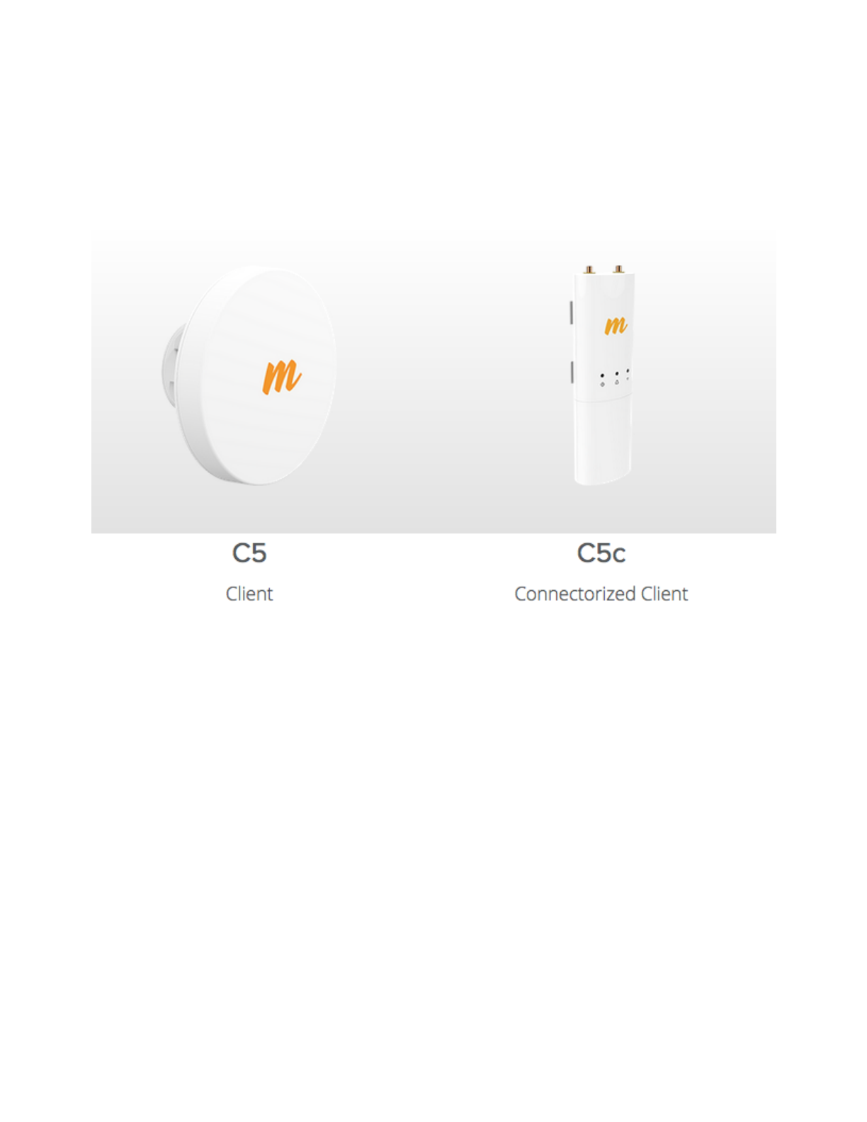
Mimosa C5/C5c Client Manual
Copyright © Mimosa. All rights reserved.
http://client.help.mimosa.co/
The information contained in this document is subject to change without notice.
This document contains proprietary information which is protected by copyright.
All rights are reserved. No part of this document may be photocopied, reproduced,
or translated to another language without the prior written consent of Mimosa.

Mimosa Client Help Content
Mimosa Clients Troubleshooting Guide
Copyright © 2014 Mimosa Page
Table of Contents
FAQ's 1 ..........................................................................................................................................................
Setup 1 ...................................................................................................................................................
Default IP Address 1 ........................................................................................................................
Reset Process 3 ...............................................................................................................................
Reset C5/C5c 3 .........................................................................................................................
Serial Number Location 6 .........................................................................................................
Performance 8 ........................................................................................................................................
SNR Required for each MCS 8 .........................................................................................................
Error Vector Magnitude (EVM) 9 ......................................................................................................
Quality of Service (Qos) 10 ..............................................................................................................
Specifications 12 ....................................................................................................................................
Receiver Sensitivity 12 ....................................................................................................................
Hardware & Materials 13 .................................................................................................................
Power over Ethernet (PoE) 14 ..........................................................................................................
Installation Guide 16 .....................................................................................................................................
Installation Overview 16 .........................................................................................................................
Mounting & Grounding 17 ......................................................................................................................
C5 Mounting and Grounding 17 .......................................................................................................
C5c Mounting and Grounding 22 .....................................................................................................
NID Details 26 .................................................................................................................................
Power & Data Connections 29 ................................................................................................................
PoE Connections 29 .........................................................................................................................
Client Setup 32 .......................................................................................................................................
Client Setup 32 ................................................................................................................................
User Guide 33 ................................................................................................................................................
Overview 33 ...........................................................................................................................................
General 33 .......................................................................................................................................
Accessing the Interface 34 ..............................................................................................................
Logging In 35 ...................................................................................................................................
User Interface Overview 36 .............................................................................................................
Dashboard 38 .........................................................................................................................................
Dashboard Overview 38 ..................................................................................................................
Signal Meter 39 ...............................................................................................................................
Performance 40 ...............................................................................................................................
Device Details 41 ............................................................................................................................
MIMO Status 43 ...............................................................................................................................
Wireless 46 .............................................................................................................................................
Channel & Power 46 ........................................................................................................................
Spectrum Analyzer 46 ..............................................................................................................
Channel & Power Settings 47 ...................................................................................................
Link 48 .............................................................................................................................................

Mimosa Client Help Content
Mimosa Clients Troubleshooting Guide
Copyright © 2014 Mimosa Page
Device Configuration 48 ...........................................................................................................
Rate Limit 49 ............................................................................................................................
Link Configuration 50 ...............................................................................................................
Location 52 ......................................................................................................................................
Local Coordinates 52 ................................................................................................................
Remote Coordinates 53 ............................................................................................................
Distance 54 ..............................................................................................................................
Site Survey 55 .................................................................................................................................
Survey Results 55 .....................................................................................................................
Preferences 56 .......................................................................................................................................
General 56 .......................................................................................................................................
Naming 56 ................................................................................................................................
Time 57 ....................................................................................................................................
Set Password 58 .......................................................................................................................
Miscellaneous 59 ......................................................................................................................
Management 60 ..............................................................................................................................
Management IP 60 ...................................................................................................................
Watchdog 61 ............................................................................................................................
Services 62 ...............................................................................................................................
Management VLAN 63 ..............................................................................................................
Miscellaneous 64 ......................................................................................................................
Notifications 65 ...............................................................................................................................
SNMP Notifications 65 ..............................................................................................................
SNMP Traps 66 .........................................................................................................................
System Log Notifications 68 .....................................................................................................
System Log Traps 69 ................................................................................................................
Firmware & Reset 70 .......................................................................................................................
Firmware Update 70 .................................................................................................................
Reset & Reboot 71 ...................................................................................................................
Backup & Restore 72 .......................................................................................................................
Backup & Restore 72 ................................................................................................................
Diagnostics 73 ........................................................................................................................................
Tests 73 ...........................................................................................................................................
Tests 73 ....................................................................................................................................
Ping 74 .....................................................................................................................................
Traceroute 75 ...........................................................................................................................
Logs 76 ............................................................................................................................................
Log Overview 76 .......................................................................................................................
SNMP Interface 77 ..................................................................................................................................
SNMP OID Reference Tables 77 .......................................................................................................
Troubleshooting Guide 82 .............................................................................................................................
Overview 82 ...........................................................................................................................................
LED Status 83 .........................................................................................................................................
Ethernet Speed 85 ..................................................................................................................................

Mimosa Client Help Content
Mimosa Clients Troubleshooting Guide
Copyright © 2014 Mimosa Page
Radios not associated 88 ........................................................................................................................
No DHCP IP Address 89 ..........................................................................................................................
Low SNR 90 ............................................................................................................................................
High PER 91 ............................................................................................................................................
Low Rx Power 92 ....................................................................................................................................
Low TCP Throughput 93 .........................................................................................................................
Throughput Testing 94 ...........................................................................................................................
Mimosa Client Help Content
Mimosa Clients Setup
Copyright © 2014 Mimosa Page 1
Default IP Address
Mimosa client radios can be accessed via the wired interface, which can either be set manually to a static IP or
changed dynamically via DHCP.
Notes: The wired Ethernet interface is configured by default to use DHCP with a static failover to the IP
Notes: The wired Ethernet interface is configured by default to use DHCP with a static failover to the IP
address in the table below.
address in the table below.
Value Wired Ethernet
IP Address 192.168.1.20
Subnet Mask 255.255.255.0
IP Address Discovery
Run the following command from the command line to discover the IP addresses of any directly connected Mimosa
devices. The string "20:B5:C6" is an Organizationally Unique Identifier (OUI), which is the first half of the MAC
address assigned to Mimosa devices. After executing the command, the IP address will be shown for each device.
Windows / DOS:
arp -a | findstr -i 20-B5-C6
Mac / Linux:
arp -a | grep -i 20:B5:C6
No CDP / LLDP Support
Mimosa radios do not respond to either CDP or LLDP at this time.
Related:
Client Setup Overview - Detailed process for configuring your device

Mimosa Client Help Content
Mimosa Clients Setup
Copyright © 2014 Mimosa Page 2
Reset Process - Explains how to recover/reset a device if needed

Mimosa Client Help Content
Mimosa Clients Reset Process
Copyright © 2014 Mimosa Page 3
Local Device Reset
Product Applicability: C5, C5c
This process is to restore the device to the factory state when the device is physically available.
This process is to restore the device to the factory state when the device is physically available.
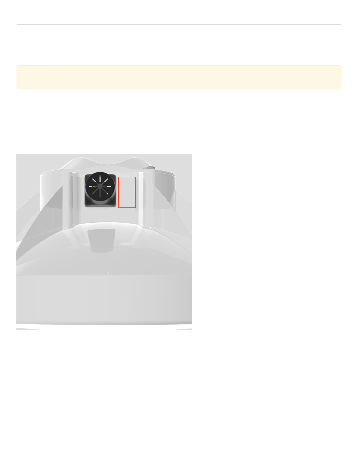
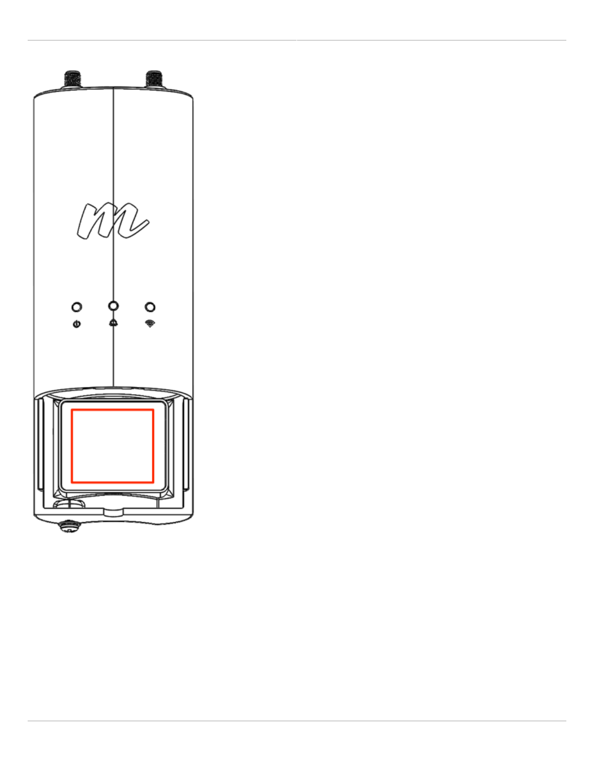
Follow these steps to reset the radio:
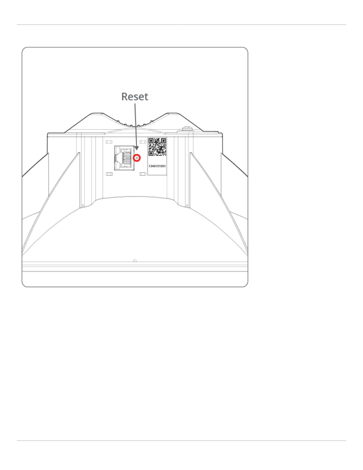
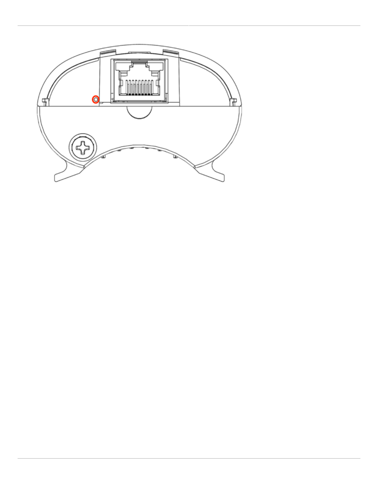
Disconnect the Ethernet cable from the radio.1.
Insert a paper clip into the hole next to the Ethernet port to depress the reset button (see image below).2.
Plug the Ethernet cable back in while holding the reset button down. The green LED will blink slowly after 23.
seconds, and then fast after 4 seconds.
Let go of the reset button when the green LED starts blinking fast.4.
The radio will then reboot for approximately 90 seconds.5.
Connect your computer to the LAN input of the PoE.6.
With a web browser, navigate to 192.168.1.20 (or address assigned by DHCP). The default password is7.
mimosa.
C5 Reset Button
Mimosa Client Help Content
Mimosa Clients Reset Process
Copyright © 2014 Mimosa Page 4
C5c Reset Button
Mimosa Client Help Content
Mimosa Clients Reset Process
Copyright © 2014 Mimosa Page 5
After factory reset, access the device with the default IP address and password, then follow the unlock process again
before reuse. It is also good practice to create a configuration backup such that it can be restored in the case of lost
passwords.
Mimosa Client Help Content
Mimosa Clients Reset Process
Copyright © 2014 Mimosa Page 6
Finding the Serial Number
The Mimosa serial number is a 10-digit number used to differentiate radios. This unique number is used as
The Mimosa serial number is a 10-digit number used to differentiate radios. This unique number is used as
part of the unlock process to ensure genuine product assurance.
part of the unlock process to ensure genuine product assurance.
There are two ways to find the Serial number on a Mimosa radio:
On the back of the radio, you can find the serial number next to the QR code (see images below).1.
Within the user interface, you can find the serial number on the Dashboard under Device Details.2.
C5 Serial Number Label
C5c Serial Number Label
Mimosa Client Help Content
Mimosa Clients Reset Process
Copyright © 2014 Mimosa Page 7

Mimosa Client Help Content
Mimosa Clients Performance
Copyright © 2014 Mimosa Page 8
SNR Required for Each MCS
The table below shows the SNR required for each MCS index as well as the modulation, coding and data rate per
stream based on channel width in MHz. Note that each channel uses up to two streams.
Examples:
2 x 80 MHz channels operating at MCS 8 with 4 streams would yield 1560 Mbps (390 Mbps * 4 streams).
●
1 x 40 MHz channel operating at MCS 6 with 2 streams would yield 270 Mbps (135 Mbps * 2 streams).
●
Modulation and Coding Scheme (MCS) PHY Data Rate (Mbps/stream)
Index Modulation Coding Required SNR (dB) 20 MHz 40 MHz 80 MHz
0 BPSK 1/2 5 7.2 15 32.5
1 QPSK 1/2 7.5 14.4 30 65
2 QPSK 3/4 10 21.7 45 97.5
3 16-QAM 1/2 12.5 28.9 60 130
4 16-QAM 3/4 15 43.3 90 195
5 64-QAM 2/3 17.5 57.8 120 260
6 64-QAM 3/4 20 65 135 292.5
7 64-QAM 5/6 22.5 72.2 150 325
8 256-QAM 3/4 25 86.7 180 390
9 256-QAM 5/6 27.5 n/a 200 433
Related:
Client FAQ: What is the sensitivity for each MCS index?

Mimosa Client Help Content
Mimosa Clients Performance
Copyright © 2014 Mimosa Page 9
Error Vector Magnitude (EVM)
The error vector magnitude or EVM describes how well the receiver can detect symbols (data) within a constellation
of symbols on the I-Q plane for a particular modulation. It is the difference in RMS power between the point where a
symbol is received and where the symbol should be. This difference is caused by noise. When analyzing EVM, the
lower the number the better.
EVM (dB) EVM (%) Assessment
0 100.0 Poor
-5 56.2 Poor
-10 31.6 Poor
-15 17.8 OK
-20 10.0 Good
-25 5.6 Good
-30 3.2 Excellent
-35 1.8 Excellent
Mimosa Client Help Content
Mimosa Clients Performance
Copyright © 2014 Mimosa Page 10
Quality of Service (QoS) Support
Mimosa radios support four different L2/L3 QoS queues for traffic prioritization. Typically, an upstream router sets
values for CoS (L2), or DSCP/TOS (L3) for specific traffic on the post-routing chain. After packets leave the router,
they enter the radio where the traffic is queued and sent according to the packet marking. While the radio does not
function as a router, it does respect packet markings assigned by the upstream router.
Note that these settings can be set or overridden by either A5 Access Control Lists or Application
Note that these settings can be set or overridden by either A5 Access Control Lists or Application
Prioritization.
Prioritization.
The table below lists the four QoS queues and corresponding prioritization values for various traffic marking
standards.
Traffic Queue IEEE P802.1p
(VLAN CoS Priority) TOS DSCP Mimosa Weighting
(% of capacity)
BE 0 0-31 0-7 20
BK 1 32-63 8-15 10
BK 2 64-95 16-23 10
BE 3 96-127 24-31 20
VI 4 128-159 32-39 30
VI 5 160-191 40-47 30
VO 6 192-223 48-55 40
VO 7 224-255 56-63 40
where,
BK = Background (lowest priority)
BE = Best Effort
VI = Video
VO = Voice (highest priority)
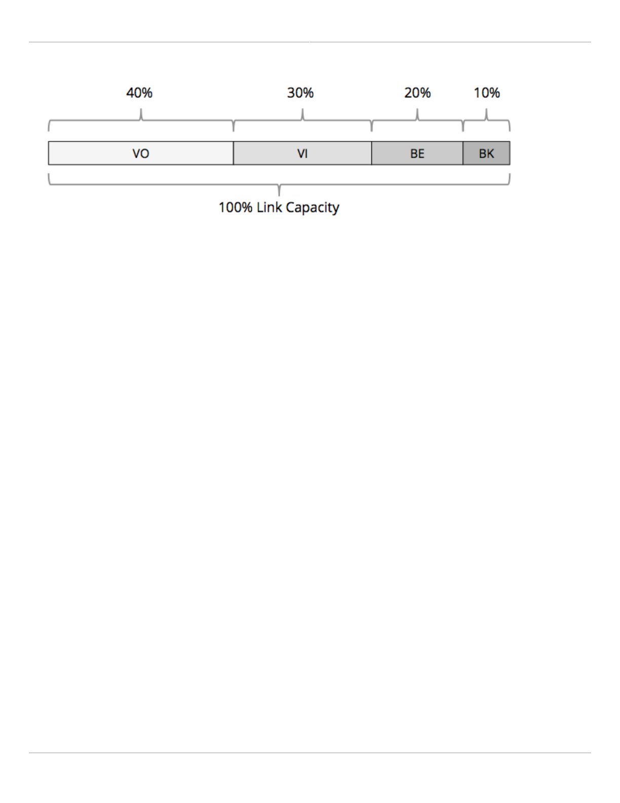
Mimosa QoS Weighting
Mimosa radios dynamically allocate link capacity by expanding or contracting each traffic queue based on the
current mix of marked traffic. If there is no traffic in a particular queue, that capacity is divided between the other
queues according to their relative weights. Unmarked traffic is processed in the Best Effort (BE) queue by default.
Mimosa Client Help Content
Mimosa Clients Performance
Copyright © 2014 Mimosa Page 11

Mimosa Client Help Content
Mimosa Clients Specifications
Copyright © 2014 Mimosa Page 12
Client Receiver Sensitivity
Product Applicability: C5, C5C
The table below shows sensitivity in dBm for each MCS index.
Channel Width
MCS Index 20 MHz 40 MHz 80 MHz
9 -70.5 -67.5 -64.5
8 -73.0 -70.0 -67.0
7 -75.5 -72.5 -69.5
6 -78.0 -75.0 -72.0
5 -80.5 -77.5 -74.5
4 -83.0 -80.0 -77.0
3 -85.5 -82.5 -79.5
2 -88.0 -85.0 -82.0
1 -90.5 -87.5 -84.5
0 -93.0 -90.0 -87.0

Mimosa Client Help Content
Mimosa Clients Specifications
Copyright © 2014 Mimosa Page 13
Enclosure Ratings
The IP is short for International Protection Marking described in IEC standard 60529. This standard classifies and
rates the degree of protection provided against the intrusion of solid objects and liquids into electrical enclosures.
The two numbers that follow are used to specify the degree of protection. The higher the number, the better the
protection. The first number refers to protection against solid objects. The second number refers to protection
against against liquids.
IP55 (C5)
The 5 rating means that the enclosure allows some dust to enter, but not in sufficient quantity to interfere with
●
satisfactory operation of the equipment.
The 5 rating means that the enclosure is protected against the effect of water projected by a nozzle (6.3 mm)
●
against the enclosure from any direction.
Mounting Hardware
Product Applicability: C5, C5c
Mounting hardware is provided standard for the C5.
The C5 hardware is made from stainless steel, including the hose clamp and ground screw.
FlexiMount and J-Mount
Both the FlexiMount and J-Mount are Steel, Zinc-plated, and powder-coated white. The included hardware is
galvanized Steel.

Mimosa Client Help Content
Mimosa Clients Specifications
Copyright © 2014 Mimosa Page 14
Power over Ethernet Specifications
Voltage Specifications
Mimosa radios require 48 volts, but they accept an input range of 44 to 57 volts on a wide variety of pin
combinations. An input voltage of -48 Vdc is also acceptable. The Mimosa PoE for C5 provides 56 volts on 2 pairs of
wires so there is less voltage drop over long cable runs up to 100 m (328 feet).
C5 radios are compatible with
C5 radios are compatible with passive
passive PoE only. Do not use an 802.3at or 802.3af PoE with C5.
PoE only. Do not use an 802.3at or 802.3af PoE with C5.
Reverse Polarity Protection
All Mimosa radios include a diode bridge circuit which corrects for reverse polarity on the power inputs, and
improves compatibility with 3rd-party PoE injectors and switches that meet the power specifications2.
Table 1 below shows valid combinations of +VE and -VE to the B5/B5c on either 2 or 4 wire pairs. All of the
combinations below will work so long as the Ethernet signal pairs are connected per the wiring standard.
Ethernet Wiring and Signals 4-Pair PoE Options 2-Pair PoE Options
Ethernet
Pin
T568A
Pair
T568B
Pair
1000BASE-T
Signal ID 1 2 3 4 5 6 1 2 3 4 5 6 7 8 9 10 11 12
1 3 2 DA+ + + + - - - + + + - NA NA - NA NA - NA NA
2 3 2 DA- + + + - - - + + + - NA NA - NA NA - NA NA
3 2 3 DB+ + - - + - + - NA NA + + + NA - NA NA - NA
4 1 1 DC+ - + - - + + NA - NA NA - NA + + + NA NA -
5 1 1 DC- - + - - + + NA - NA NA - NA + + + NA NA -
6 2 3 DB- + - - + - + - NA NA + + + NA - NA NA - NA
7 4 4 DD+ - - + + + - NA NA - NA NA - NA NA - + + +
8 4 4 DD- - - + + + - NA NA - NA NA - NA NA - + + +
Table 1 – Radio Input Voltage Polarization Compatibility
Notes:
Performance will be limited if a 10/100BASE-T PoE is used. Mimosa client radios are designed for speeds that1.
exceed the capability of these standards.
Some 3rd-party PoE injectors may not have a sufficient power budget to deliver full power to all of their ports2.
depending on how many other PoE-powered devices are installed and how much power each device draws.

Mimosa Client Help Content
Mimosa Clients Specifications
Copyright © 2014 Mimosa Page 15
Related:
Product Specifications: C5, C5c

Mimosa Client Help Content
Mimosa Clients Installation Guide
Copyright © 2014 Mimosa Page 16
Client Installation Overview
The C5 ships with this 2-page User Guide. Below are more detailed instructions for each step of the installation
process.
C5
Follow the Radio Unlock process.1.
Follow the Mounting and Grounding process.2.
Follow the POE Connection process.3.
Follow the Client Setup process.4.
C5c
Follow the Radio Unlock process.1.
Follow the Mounting and Grounding process.2.
Follow the POE Connection process.3.
Follow the Client/Station Setup process.4.

Mimosa Client Help Content
Mimosa Clients Mounting & Grounding
Copyright © 2014 Mimosa Page 17
Mounting and Grounding the C5
This process ensures that the radio is securely attached to a building or tower and is grounded to protect
This process ensures that the radio is securely attached to a building or tower and is grounded to protect
against electrical discharge.
against electrical discharge.
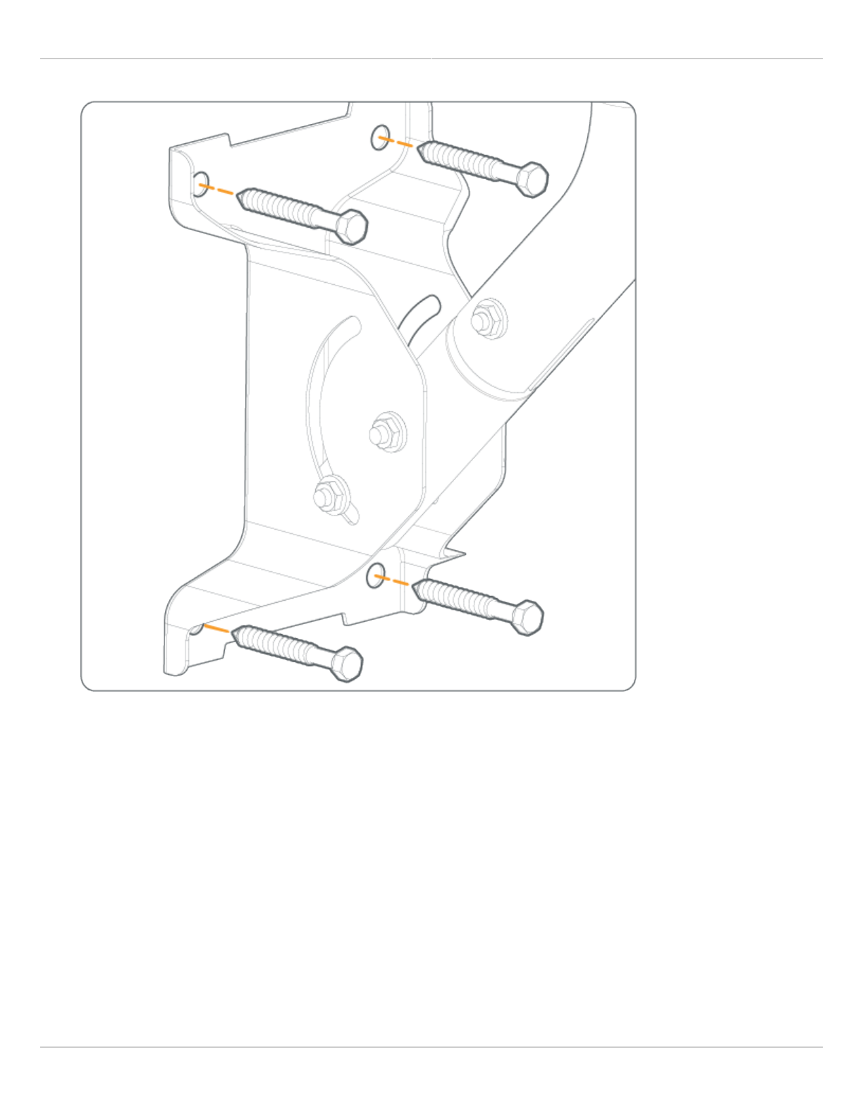
Follow these steps to mount and ground the C5 Radio.
Attach the Bracket Assembly to a solid surface with four provided bolts. The holes at each end of the Bracket1.
Assembly are spaced at 90 mm (3.54 inches) on center.
Optionally, the bottom portion of the J-mount tube can be separated from the Bracket Assembly and affixed
securely to a commercially available crossover plate with u-bolts, or a traffic camera clamp kit. The J-mount
tube is 38.1 mm (1.5 inches) in diameter.
Mimosa Client Help Content
Mimosa Clients Mounting & Grounding
Copyright © 2014 Mimosa Page 18
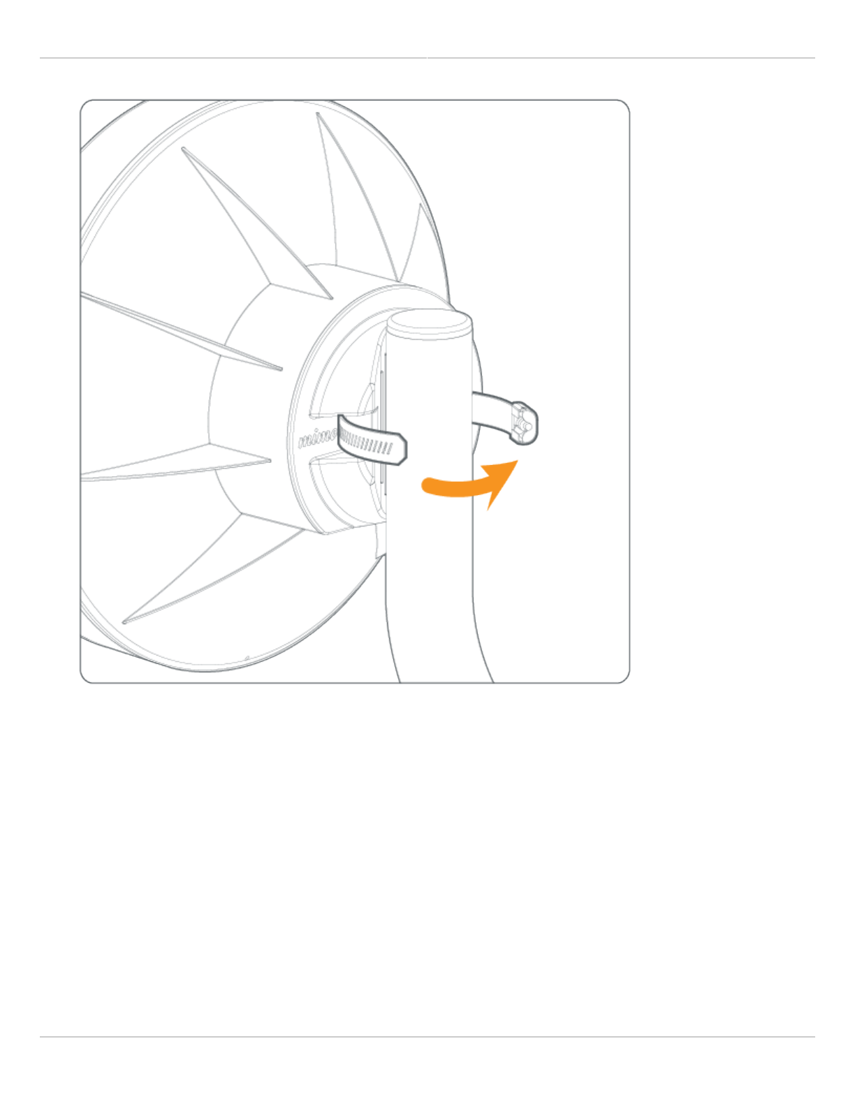
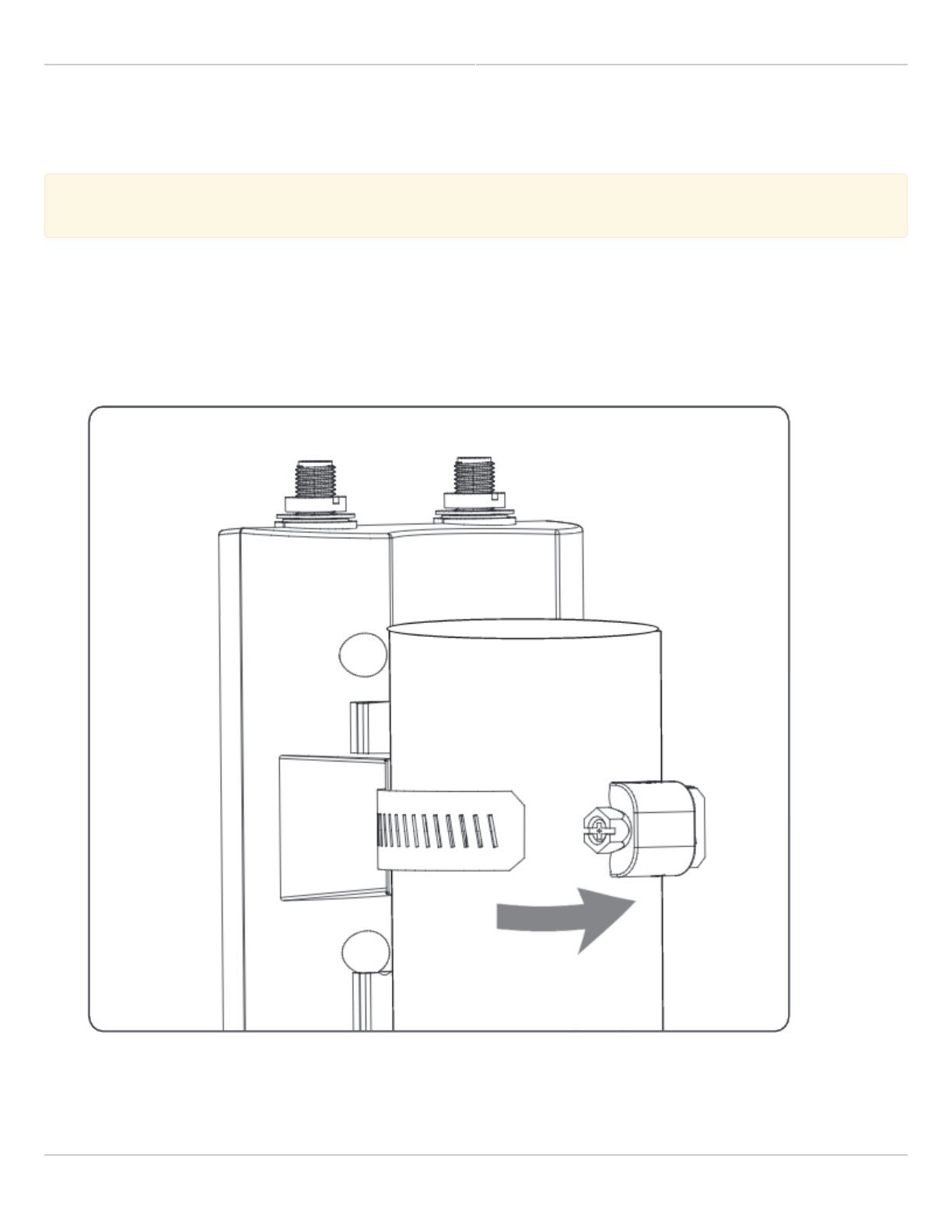
Mount the C5 on the J-Mount using the pipe clamp.2.
Mimosa Client Help Content
Mimosa Clients Mounting & Grounding
Copyright © 2014 Mimosa Page 19
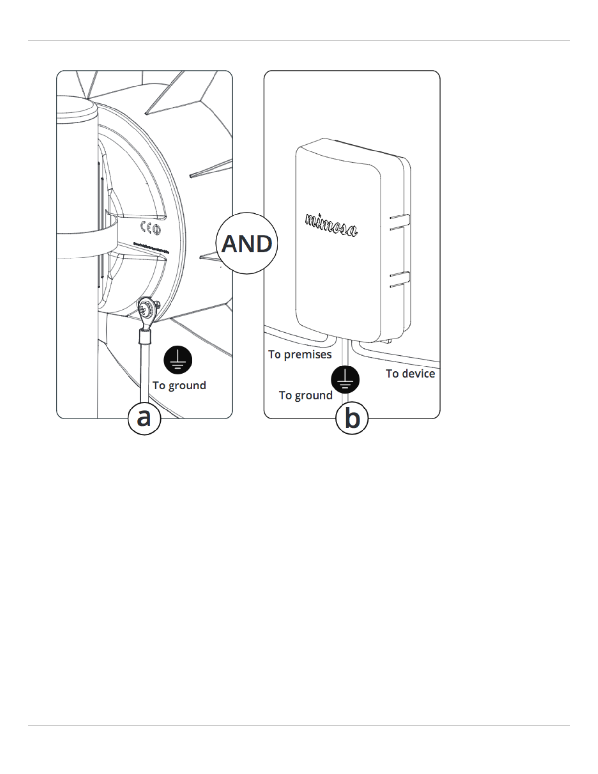
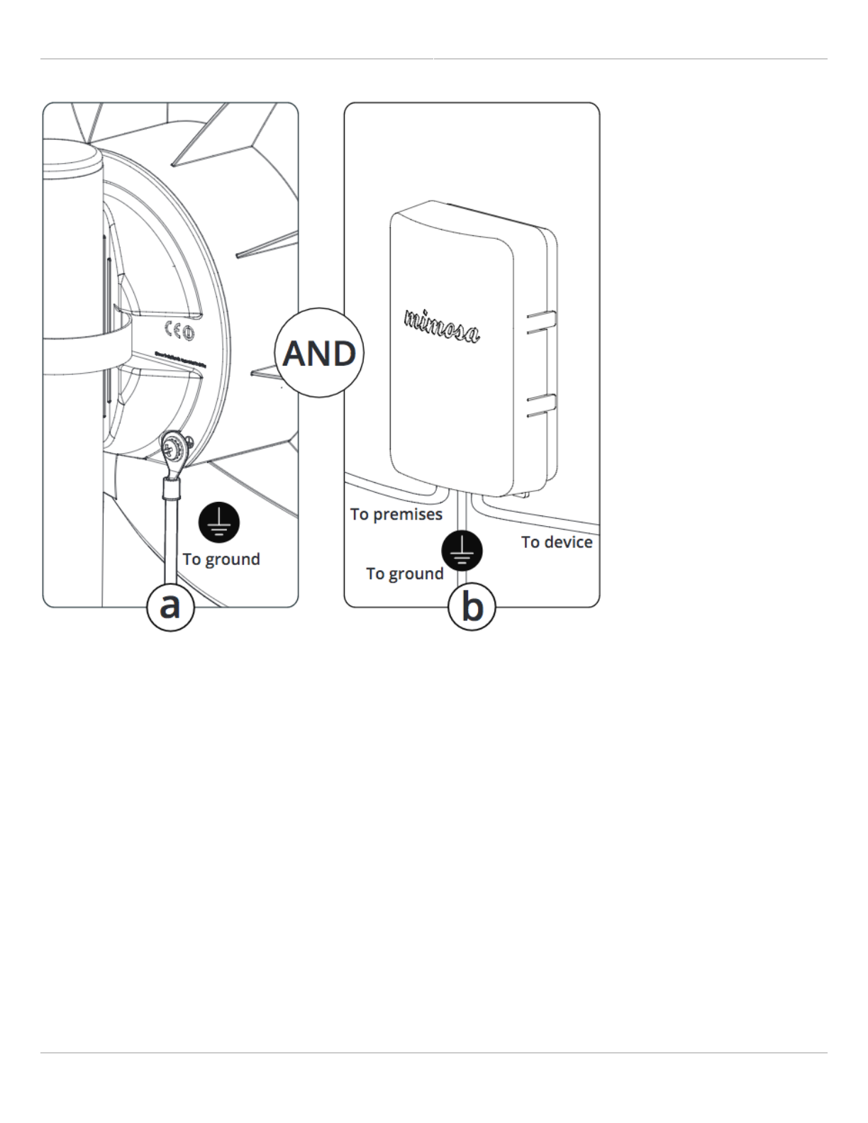
Attach to Earth Ground3.
a) Attach a 6 mm2 (10 AWG) ground wire (not included) between the C5 and a suitable grounding location. The
provided ground screw is M4 x 4mm with 0.7 thread.
b) Install the Mimosa Gigabit NID at the entry point for Electrostatic Discharge (ESD) protection.
Mimosa Client Help Content
Mimosa Clients Mounting & Grounding
Copyright © 2014 Mimosa Page 20
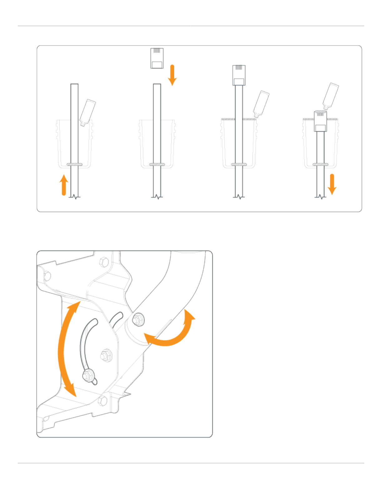
Prepare the Ethernet Cabling (not included) and provided protective boot. Push shielded CAT6 cable through4.
hole in the bottom of the boot, applying the provided dielectric silicone around base of boot around cable
entry. Crimp a metal RJ45 connector to the CAT6 cable and ensure that the cable shield makes contact with
the metal shroud on the RJ45 connector. Apply dielectric silicone around top lip of boot. Pull CAT6 cable back
through boot leaving enough to connect to device. Apply a small amount of dielectric silicone to pins. Insert
the cable into the RJ45 receptacle and attach the boot to the radio body.
Mimosa Client Help Content
Mimosa Clients Mounting & Grounding
Copyright © 2014 Mimosa Page 21
Aim the radio using physical Elevation and Azimuth adjustments on the J-Mount, then check and tighten each5.
of the 10 mm hex nuts until secure.
Mimosa Client Help Content
Mimosa Clients Mounting & Grounding
Copyright © 2014 Mimosa Page 22
Mounting and Grounding the C5c
This process ensures that the radio is securely attached and grounded to protect against electrical
This process ensures that the radio is securely attached and grounded to protect against electrical
discharge.
discharge.
Follow these steps to mount and ground the C5c Radio.
Mount the radio1.
Attach the C5c to the desired pole location using the included pole clamp, or directly snap the C5c into an
antenna supporting the integrated mount clips.
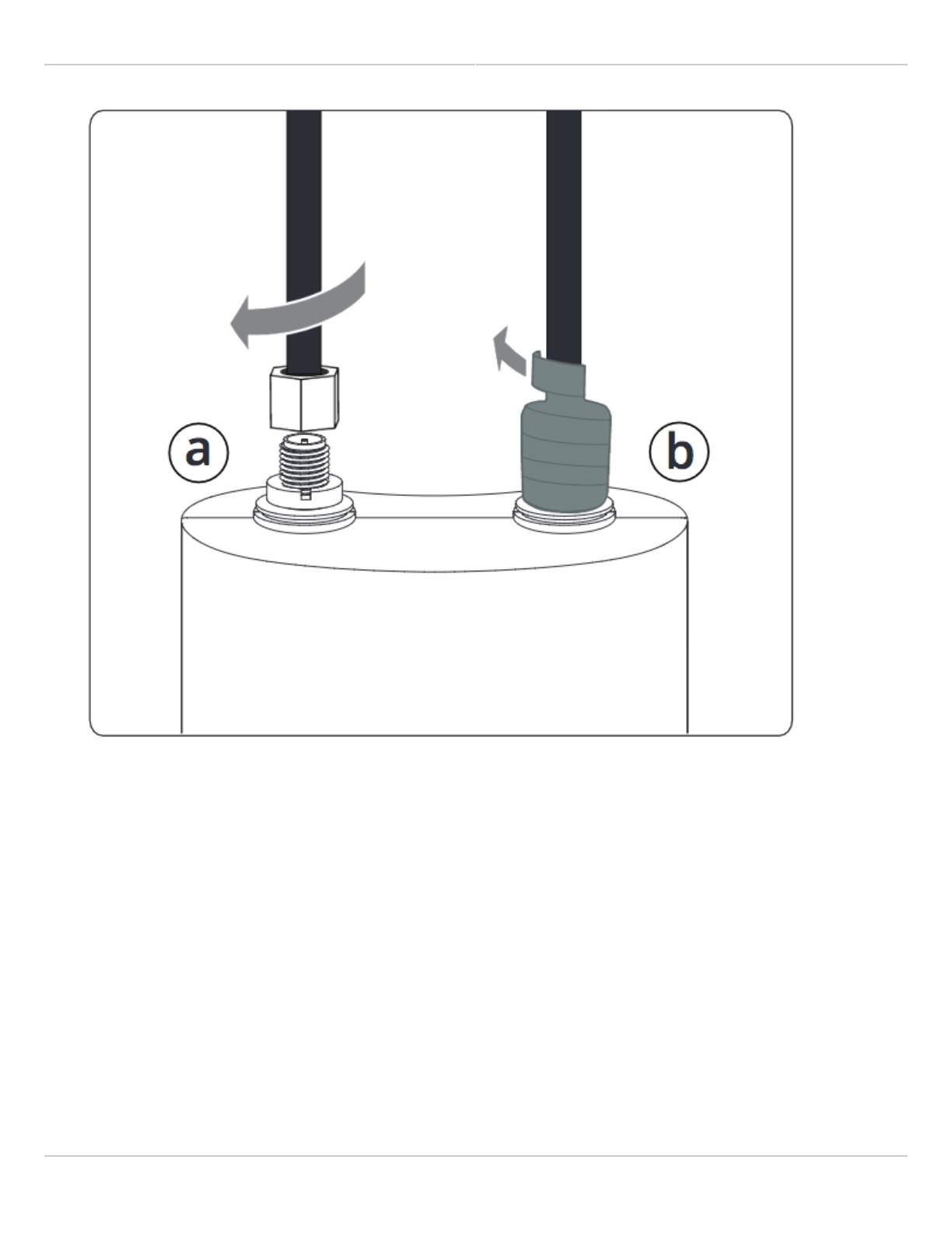
Connect Antenna Cabling2.
a) Connect both RP-SMA male type jumper cables between the chosen antenna and the C5c and tighten.
b) Using the provided strips of mastic tape, wrap both of the tightened connectors from the bottom up.
Mimosa Client Help Content
Mimosa Clients Mounting & Grounding
Copyright © 2014 Mimosa Page 23
C
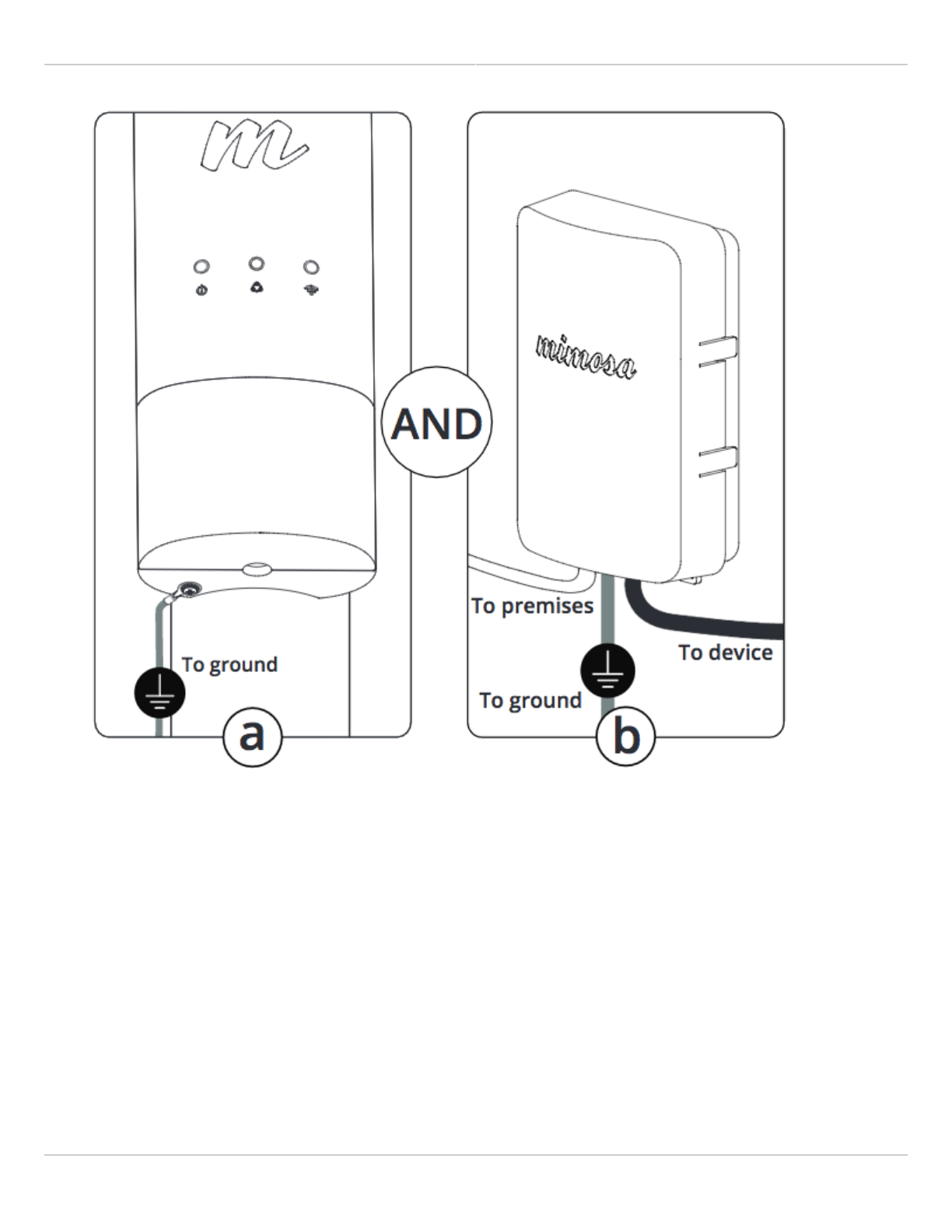
Attach to Earth Ground3.
a) Attach a 6 mm2 (10 AWG) ground wire (not included) between the C5c and a suitable grounding location.
The provided ground screw is M4 x 4mm with 0.7 thread.
b) Install the Mimosa Gigabit NID at the entry point for Electrostatic Discharge (ESD) protection.
Mimosa Client Help Content
Mimosa Clients Mounting & Grounding
Copyright © 2014 Mimosa Page 24
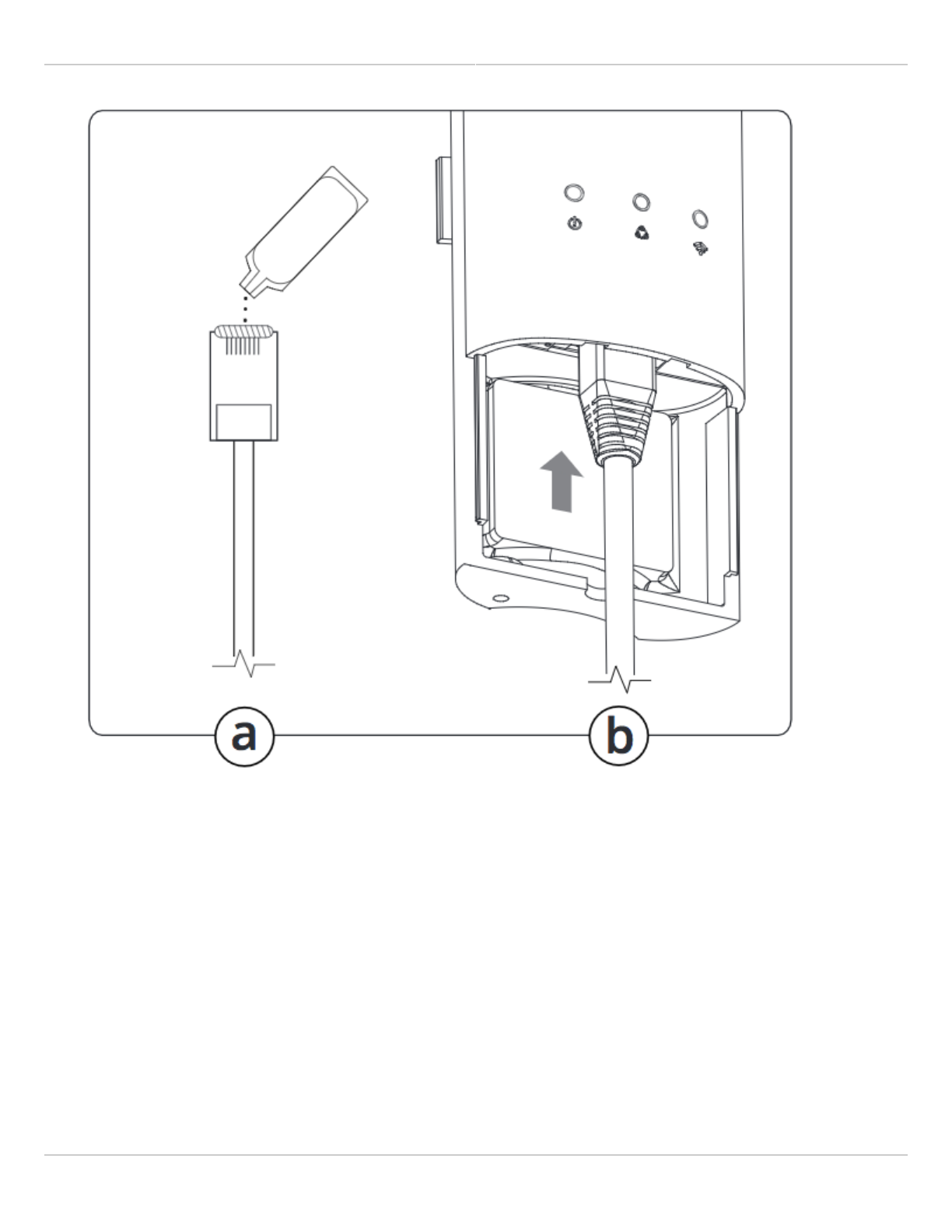
Connect Ethernet4.
a) Prepare the shielded CAT6 Cabling (not included), and apply a bead of dielectric silicone to Ethernet pins.
b) Remove the front plastic cover from the radio, connect the Ethernet cable, and then replace the cover.
Mimosa Client Help Content
Mimosa Clients Mounting & Grounding
Copyright © 2014 Mimosa Page 25
M

Mimosa Client Help Content
Mimosa Clients Mounting & Grounding
Copyright © 2014 Mimosa Page 26
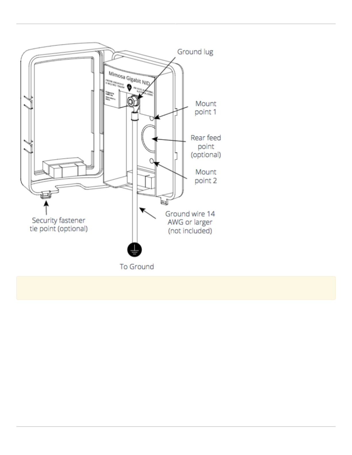
Network Interface Device (NID)
Overview
The NID serves two purposes:
It was designed first to protect against surge energy from entering a structure in compliance with electrical1.
codes. There is no surge protection on the C5, PoE or G2, and only the C5 and NID have metal shielded
Ethernet inputs. While the Ethernet cable shield can behave like a ground (and many service providers treat it
as such), it is not a code-compliant grounding solution for surge currents as the cross-sectional area does not
have the current carrying capacity of a larger ground wire that would normally be specified for building safety.
The NID also serves as a demarcation point for the external portion of service, and provides outdoor technician2.
access so that they don’t have to schedule time with a building occupant for testing or troubleshooting
between the C5 and A5. Some providers charge end users more money if the problem is inside the building
rather than outside.
Mimosa Client Help Content
Mimosa Clients Mounting & Grounding
Copyright © 2014 Mimosa Page 27
Security
A security fastener tie point is included at the bottom of the NID to thwart and provide evidence of causal
tampering. If an unauthorized party wishes to access the network, they could also cut and re-terminate the Ethernet
cable in the absence of a NID. In either case, an they would need to bring their own DHCP router and DC power
supply to access the customer’s router, which is presumably also protected by a suitable firewall. They could access
the C5 so long as they brought a passive 48V DC power supply, but they would need to know the IP address,
password and VLAN if applicable. Most operators filter and manage traffic at upstream routers using VLAN or MAC
filtering to prevent unauthorized access such as when end customers do not pay their bill.
Mimosa Client Help Content
Mimosa Clients Mounting & Grounding
Copyright © 2014 Mimosa Page 28
Mimosa always recommends using shielded CAT6 cable for performance reasons. When using the NID,
Mimosa always recommends using shielded CAT6 cable for performance reasons. When using the NID,
Mimosa recommends connecting the cable shield to metal end connectors at both ends of the cable.
Mimosa recommends connecting the cable shield to metal end connectors at both ends of the cable.

Mimosa Client Help Content
Mimosa Clients Power & Data Connections
Copyright © 2014 Mimosa Page 29
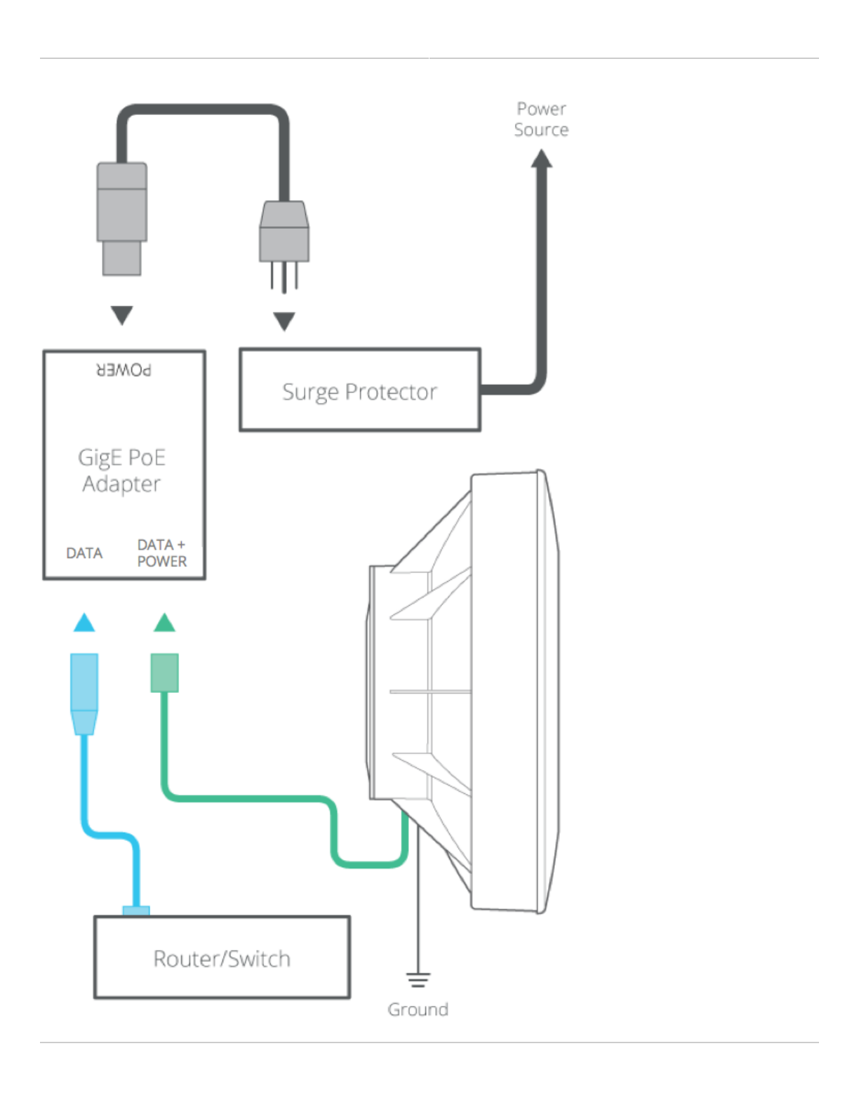
PoE Connections
This process ensures the proper PoE connection to a power source, the radio and the LAN.
This process ensures the proper PoE connection to a power source, the radio and the LAN.
Connect the provided power cable between the power over Ethernet (PoE) adapter and a power source. A1.
surge protector can be installed between the PoE and the power source, but it is not required.
Connect a shielded CAT6 Ethernet cable between the Ethernet port labeled "POE" on the GigE PoE adapter and2.
the radio.
Connect a shielded CAT6 Ethernet cable between the Ethernet port labeled "LAN" on the GigE PoE adapter and3.
the LAN side of your network, which is typically a switch or router.
Mimosa Client Help Content
Mimosa Clients Power & Data Connections
Copyright © 2014 Mimosa Page 30

Mimosa Client Help Content
Mimosa Clients Power & Data Connections
Copyright © 2014 Mimosa Page 31
Related:
LED Status Indicators - External LED behavior based on device status.

Mimosa Client Help Content
Mimosa Clients Client Setup
Copyright © 2014 Mimosa Page 32
Client Setup
This overview is intended to assist the user with preliminary radio setup prior to deployment.
Notes
Notes:
:
Internet access is required to access firmware and online help resources.
●
If the radio is connected to a DHCP server, the default IP addresses shown below will be different.
●
Download latest Firmware for your device.1.
Connect the PoE to the Radio.2.
Prepare your computer for use.3.
Connect an Ethernet cable between your computer and the PoE port labeled DATA.
●
Ensure that your computer's IP address is different from that of the radio (192.168.1.20), but in the same
●
network. The subnet mask should be the same for both devices (255.255.255.0). Consult operating system
documentation for instructions about how to change your computer's IP address.
Access the radio in a browser.4.
Open a browser and enter 192.168.1.20 in the address bar.
●
Enter a password that will be used to administer the device.
●
Install firmware image.5.
Select the firmware image from your computer downloaded in step 1 for upload. The radio will validate and
●
install the firmware, and then reboot.
Assign a friendly radio name.6.
Navigate to Preferences > General > Device Friendly Name to enter a meaningful radio name.
●
Configure the radio’s IP address.7.
Navigate to Preferences > Management > Management IP to ensure the settings match your existing
●
network configuration.
After changing the radio's IP address adjust your computer's IP address to operate on the same network.
●
Set the link details.8.
Navigate to the Wireless > Link > Link Configuration panel to set a Link Friendly Name.
●
Enter the SSID of the AP to which the Client will connect.
●
Enter the Encryption Key (Passphrase) required for the SSID.
●
Choose operating frequencies.9.
Navigate to Wireless > Channel & Power > Channel & Power Settings.
●
Choose a desired Maximum Channel Width.
●
Set Tx Power to desired level.
●

Mimosa Client Help Content
Mimosa Clients Overview
Copyright © 2014 Mimosa Page 33
General
Product Applicability: C5, C5c
FCC Compliance
This device complies with part 15 of the FCC Rules. Operation is subject to the following two conditions:
(1) This device may not cause harmful interference; and
(2) this device must accept any interference received, including interference that may cause undesired operation.
Note that user changes or modifications not expressly approved by the party responsible for compliance could void
the user's authority to operate the equipment.
RF Exposure Warning
The radiated output power of this device is below the FCC radio frequency exposure limits. Nevertheless, the device
should be used in such a manner that the potential for human contact during the normal operation is minimized. In
order to avoid the possibility of exceeding the FCC radio frequency exposure limit, human proximity to the access
point should be more than 20 cm.
Industry Canada Compliance
This device complies with Industry Canada’s license-exempt RSSs. Operation is subject to the following two
conditions:
(1) This device may not cause interference; and
(2) This device must accept any interference, including interference that may cause undesired operation of the
device.
Follow all safety precautions as dictated by your local regulator in installation.

Mimosa Client Help Content
Mimosa Clients Overview
Copyright © 2014 Mimosa Page 34
Accessing the Graphical User Interface
Accessing the graphical user interface (GUI) requires that the radio first be connected to power. The Power over
Ethernet (PoE) connection process describes the steps to do this. Note that the GUI will be available approximately
one minute after applying power.
The GUI can be accessed in two ways to facilitate set-up and management.
Through the local Ethernet interface (LAN)1.
Remotely through the AP wireless link2.
Via Ethernet interface or in-band through the AP link
By default, the device IP address is 192.168.1.20 and can be accessed via the Ethernet port using this IP address in
any standard Web browser. To access the device via a locally connected computer initially (on the same LAN or
directly to the Ethernet port), the computer’s IP address must be on the same subnet as the above address. Once
you have modified the IP address (static or is DHCP) of the device for remote management purposes (in-band over
wireless or over the Ethernet interface), the new specified IP address must be used to access the device.

Mimosa Client Help Content
Mimosa Clients Overview
Copyright © 2014 Mimosa Page 35
Logging In
After connecting via one of the access methods, the GUI will prompt you to log-in with a password. The default
password is "mimosa", and should be changed immediately after login to protect your network since it gives the
user read / write privileges. The password can be changed within the Preferences > General > Set Password panel
of the GUI.
If you are looking for the Mimosa Cloud Log In process, please see Manage User Guide: Logging In.
If you are looking for the Mimosa Cloud Log In process, please see Manage User Guide: Logging In.
Mimosa Client Help Content
Mimosa Clients Overview
Copyright © 2014 Mimosa Page 36
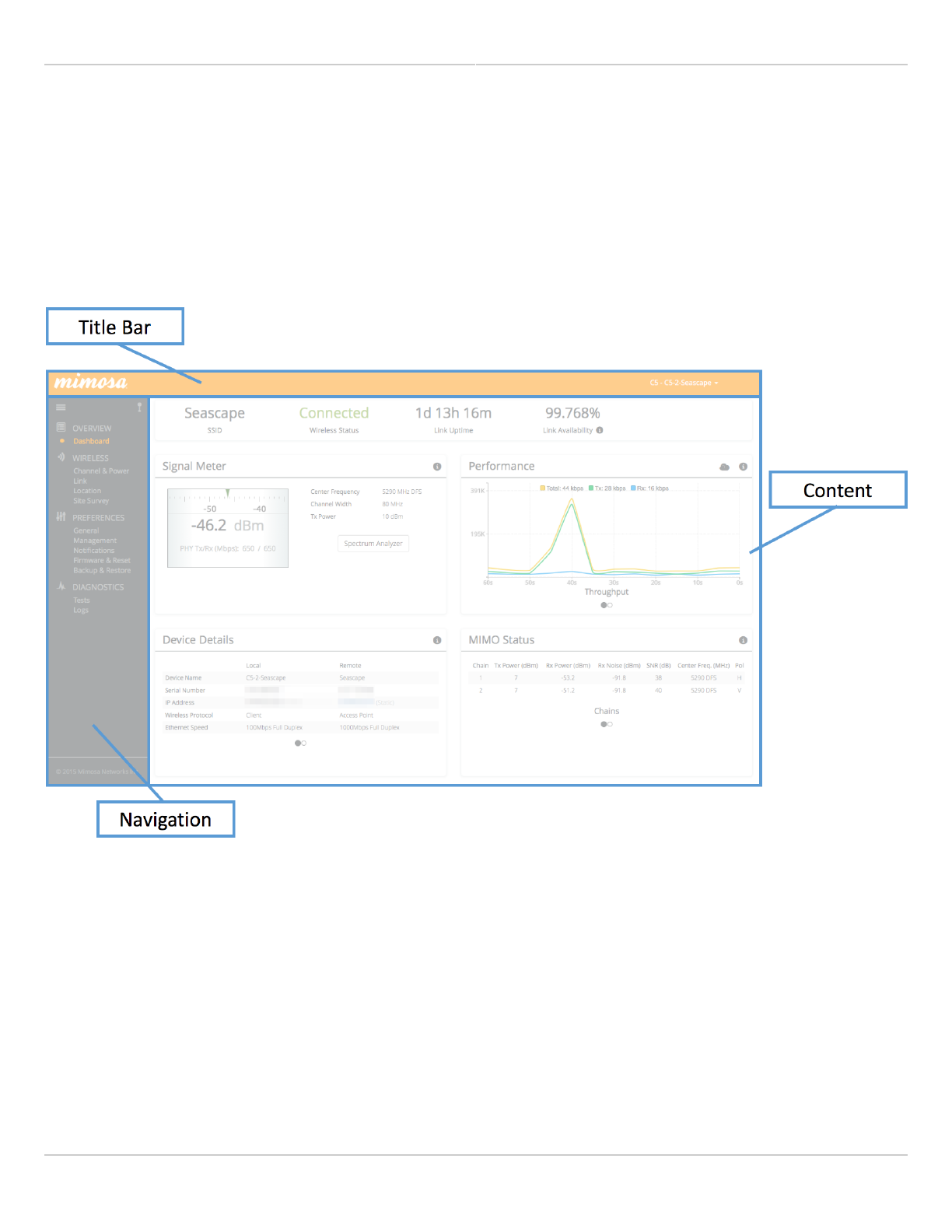
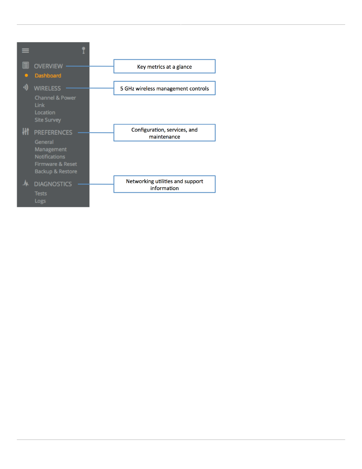
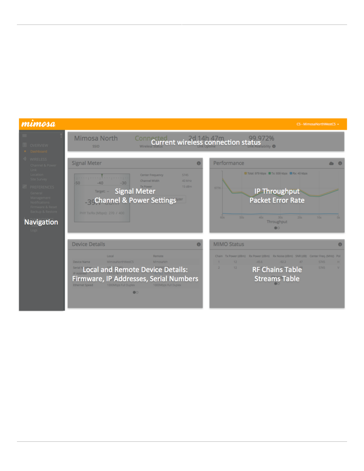
User Interface Overview
When you first log in, you’ll notice that there is a title bar with the device name shown in the top-right corner, a
navigation pane on the left, and a large content pane on the right. The default page shown in the content pane is
the Dashboard, which shows a summary of overall performance at a glance, and highlights both radio and link
parameters that affect link health.
On the left navigation pane, there are four prominent sections: Overview, Wireless, Preferences, and Diagnostics.
Each of these sections contains one or more links to pages containing task-related data, controls, and tools used to
administer the radio…and you can return the Dashboard at any time by clicking on the Dashboard link in the
Overview section.
The pin in the top corner of the left navigation pane allows you to "pin" open the navigation menu for easier access.
Else, the menu contracts to provide more workspace within the GUI.
Mimosa Client Help Content
Mimosa Clients Overview
Copyright © 2014 Mimosa Page 37
Mimosa Client Help Content
Mimosa Clients Dashboard
Copyright © 2014 Mimosa Page 38
The Dashboard
The Dashboard contains several panels used to group related items. The status panel at the top of the page shows
the link SSID, the link status, Link Uptime since association, and Link Availability since the last reboot. Two of the
values on this panel contain an information icon that shows more information when you click or hover over it with
your mouse cursor. On other panels, detailed help text can be found by clicking on the information icon in the upper
right hand corner.
Mimosa Client Help Content
Mimosa Clients Dashboard
Copyright © 2014 Mimosa Page 39
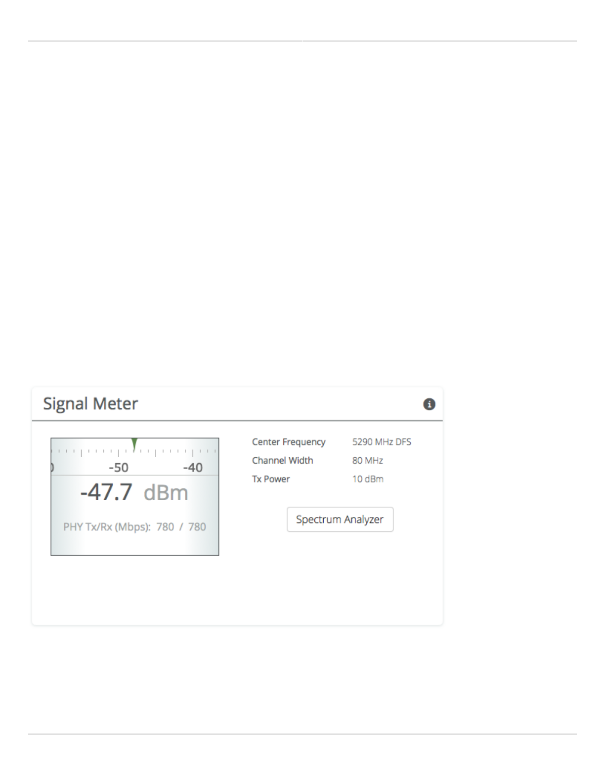
Reading the Signal Meter
Connected Link
Received signal strength is shown in large text in the center of the control, and as a green indicator in the top dial.
The objective is to align the green indicator with the blue bar as a guideline during antenna aiming.
The resulting half-duplex PHY rates shown at the bottom of the Signal Meter control are correlated with the MCS,
and represent raw data across the link without protocol overhead.
The following settings and values that affect link quality are listed for reference:
Center Frequency - True center of the first frequency range (no offset)
●
Channel Width - The selected channel width (20, 40 or 80 MHz)
●
Tx Power - Total transmit power level (dBm)
●
Click the Spectrum Analyzer button to access the Spectrum Analyzer, which can also be found on the Channel &
Power page. This will not disturb the link.
When a link is not associated, the signal strength and PHY rates are replaced by an indicator of "Disconnected".
Mimosa Client Help Content
Mimosa Clients Dashboard
Copyright © 2014 Mimosa Page 40
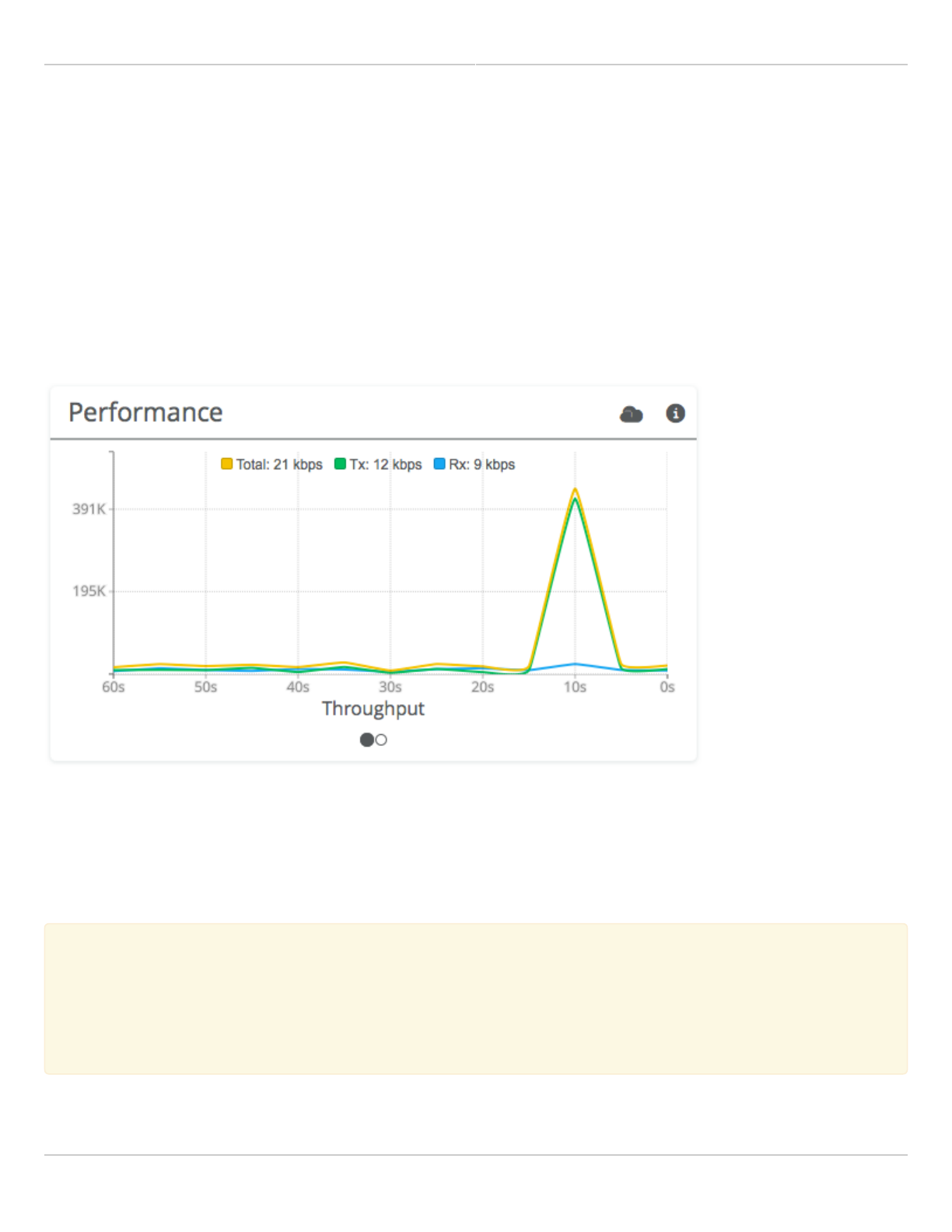
Reading the Performance Charts
IP Throughput and Packet Error Rate (PER) are charted over 60 seconds in 5-second intervals. The newest data
shows up on the right and scrolls to the left over time. You can toggle between the charts by clicking on the
navigation circles at the bottom of the panel. If enabled, click on the cloud icon to view historical data within the
Manage application.
The IP Throughput graph plots three lines representing transmit, receive, and aggregate (summed) throughputs at
Layer 2. The results here may differ from those measured using speed test tools, due to protocol overhead and
encapsulation. Note that internal Bandwidth test results are excluded.
The Packet Error Rate (PER) is the number of packets with errors divided by the total number of packets sent within
a 5-second period. Lower values result in higher modulation, while higher values indicate the presence of
interference and result in lower modulation. Tx PER is an indication that the local radio did not receive an ACK from
the remote radio, so is forced to retransmit the same information again.
Note: PER will be higher upon initial association, and will usually settle within 30-60 seconds. This is
Note: PER will be higher upon initial association, and will usually settle within 30-60 seconds. This is
because association requires that the radios “listen” more carefully for their link partner until they are
because association requires that the radios “listen” more carefully for their link partner until they are
linked, and this listening period is subject to more interference until Automatic Gain Control (AGC) and
linked, and this listening period is subject to more interference until Automatic Gain Control (AGC) and
Rate Adaptation (RA) adjust parameters to accommodate the conditions. PER values are exchanged
Rate Adaptation (RA) adjust parameters to accommodate the conditions. PER values are exchanged
between radios asynchronously, so the values may not match exactly when referencing both radios at the
between radios asynchronously, so the values may not match exactly when referencing both radios at the
same time.
same time.
Mimosa Client Help Content
Mimosa Clients Dashboard
Copyright © 2014 Mimosa Page 41
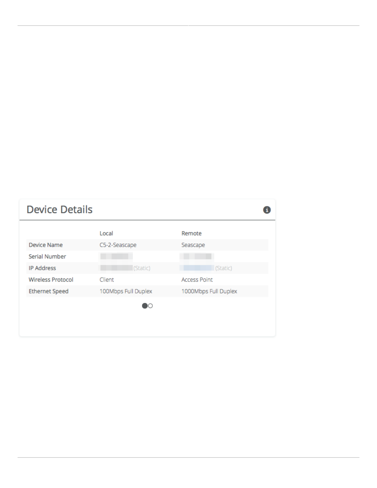
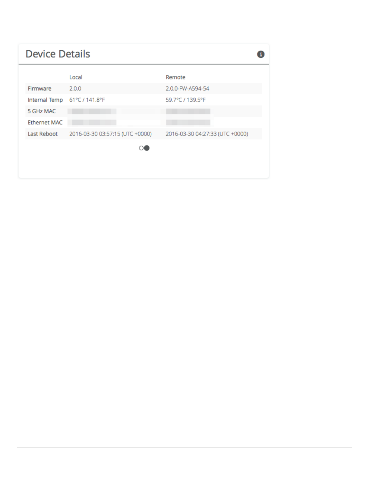
Reading Device Details
The Device Details panel shows two summary tables for the local and remote device configurations and their status.
Click on the navigation circles at the bottom of the panel to toggle between the two tables.
The table shows the following for both Local and Remote devices:
Device Name - The friendly name given to each device. (Set in Preferences > General > Naming)
●
Serial Number - The unique identifier for the device assigned at the factory.
●
IP Address - The IP address of each device and how it was assigned. (Set in Preferences > Management)
●
Wireless Mode - Client or Access Point.
●
Ethernet Speed - Data rate and duplex mode of the wired Ethernet interface.
●
Firmware - The latest firmware version applied to each device. (Set in Preferences > Update & Reboot)
●
CPU Temp - Temperature on the device CPU (operating range: -40 °C to +110 °C).
●
5 GHz MAC - The unique identifier for the 5 GHz radio.
●
Ethernet MAC - The unique identifier for the physical Ethernet interface.
●
Last Reboot - The date and time at which each device last rebooted.
●
Mimosa Client Help Content
Mimosa Clients Dashboard
Copyright © 2014 Mimosa Page 42
Mimosa Client Help Content
Mimosa Clients Dashboard
Copyright © 2014 Mimosa Page 43
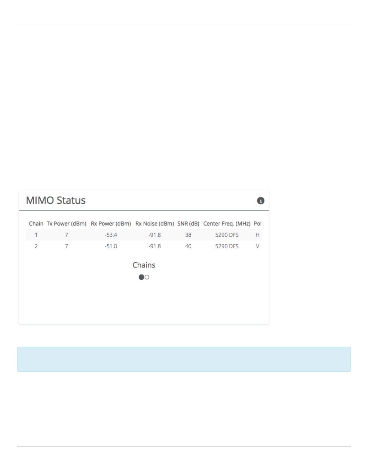
Reading MIMO Status Tables
The MIMO Status panel contains two tables: Chains and Streams. Chains represent the physical medium (RF Tx/Rx
values), while Streams represent data. Chains and Streams are not necessarily correlated one to one because the
Rate Adaptation algorithm may periodically increase or decrease the number of data streams sent over the physical
medium when reacting to interference.
The Chains table describes each chain's power, noise, SNR, frequency and polarization.
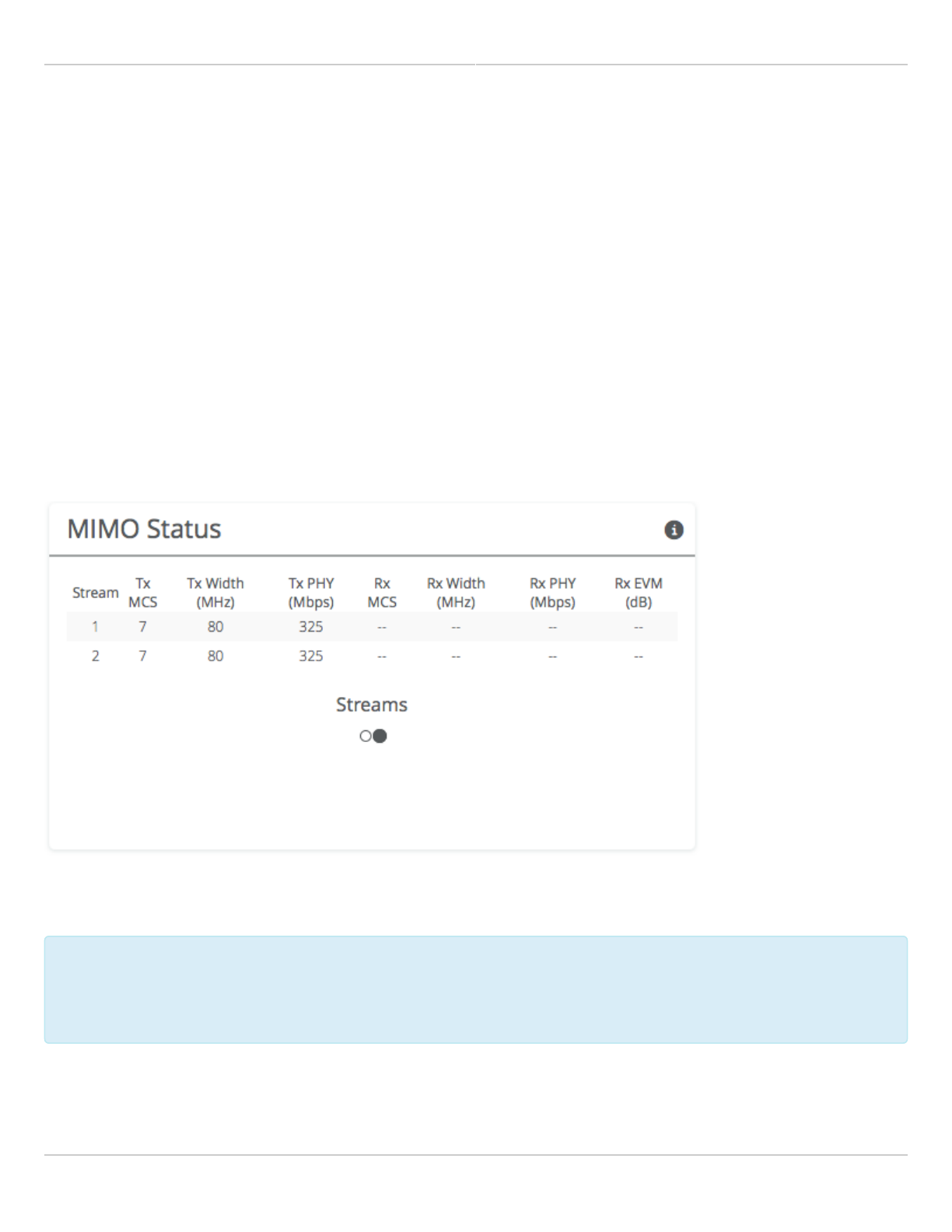
The Streams table describes each stream's MCS index, PHY rates and Rx Error Vector Magnitude (EVM).
Each table can be selected by clicking on the navigation circles at the bottom of the panel.
Chains Table
The Chains table contains 6 values: Tx Power, Rx Power, Rx Noise, SNR, Center Frequency and Polarization
(horizontal and vertical).
Tx Power is the amount of power applied to each of the MIMO chains.
Tx power is divided evenly per chain. Example: 15 dBm Tx power for the Channel results in 12 dBm on
Tx power is divided evenly per chain. Example: 15 dBm Tx power for the Channel results in 12 dBm on
each on chain. Since power is expressed in dBm, subtract 3 to divide the total power in half.
each on chain. Since power is expressed in dBm, subtract 3 to divide the total power in half.
Rx Power is the incoming signal level from the remote radio. Larger values are better (e.g. -50 dBm is better than -
60 dBm).
Rx Noise is a combination of the thermal noise floor plus interference detected by the local radio. Smaller values are
better (e.g. -90 dBm is better than -80 dBm). Noise sources can be either in close proximity to the local radio, or
they can be remote transmitters pointed back at the local radio.
Mimosa Client Help Content
Mimosa Clients Dashboard
Copyright © 2014 Mimosa Page 44
The signal-to-noise ratio (SNR) is the difference between the Rx Power and Rx Noise, and is a measure of how well
the local receiver can detect signals from the remote transmitter and clearly discern them from noise. Higher
values are better (e.g. 30 dB is better than 10 dB).
If two channels are selected, you may observe that SNR is much lower on one channel than the other. This could be
because the Tx Power is set lower on the remote transmitter, or because of higher interference levels on the
channel. To resolve this, increase Tx Power or change the channel that has lower SNR.
Chain 1 has horizontal polarization, while Chain 2 has vertical polarization.
Streams Table
The Streams table contains the Tx MCS index, Tx PHY rate, Rx MCS index, Rx PHY rate, and the Rx EVM for each
stream.
The Tx MCS is an indicator of how well the remote radio can receive data from the local transmitter. The Rx MCS
indicates how well the local radio is receiving data from the remote transmitter.
The Modulation Coding Scheme (MCS) represents how much data can be sent at a time, so directly affects
The Modulation Coding Scheme (MCS) represents how much data can be sent at a time, so directly affects
potential throughput represented by the PHY rate. The higher the MCS index (ranging from 0-9), the more
potential throughput represented by the PHY rate. The higher the MCS index (ranging from 0-9), the more
data that can be sent per transmission. A disadvantages of higher MCS indices is that they require higher
data that can be sent per transmission. A disadvantages of higher MCS indices is that they require higher
SNR since they are more vulnerable to noise.
SNR since they are more vulnerable to noise.
The Error Vector Magnitude (EVM) indicates the difference between the actual and expected amplitude and phase of
an incoming signal. Smaller values are better (e.g. -30 dB is better than -10 dB).

Mimosa Client Help Content
Mimosa Clients Dashboard
Copyright © 2014 Mimosa Page 45
Rate Adaptation dynamically adjusts both the MCS and the number of streams depending on RF conditions. Poor RF
conditions (i.e. interference) causes PER to increase. PER and MCS are inversely correlated meaning that as PER
increases, MCS decreases and vice versa.
The radio usually uses 2 streams, but it may drop to one stream if RF conditions are poor. You may also see the
number of streams change periodically because of tests that Rate Adaptation performs to optimize performance.
This is expected and normal.
Related:
Client FAQ: What SNR is required for each MCS?
Client FAQ: What is the sensitivity for each MCS index?
Client FAQ: What's a good EVM?
Mimosa Client Help Content
Mimosa Clients Channel & Power
Copyright © 2014 Mimosa Page 46
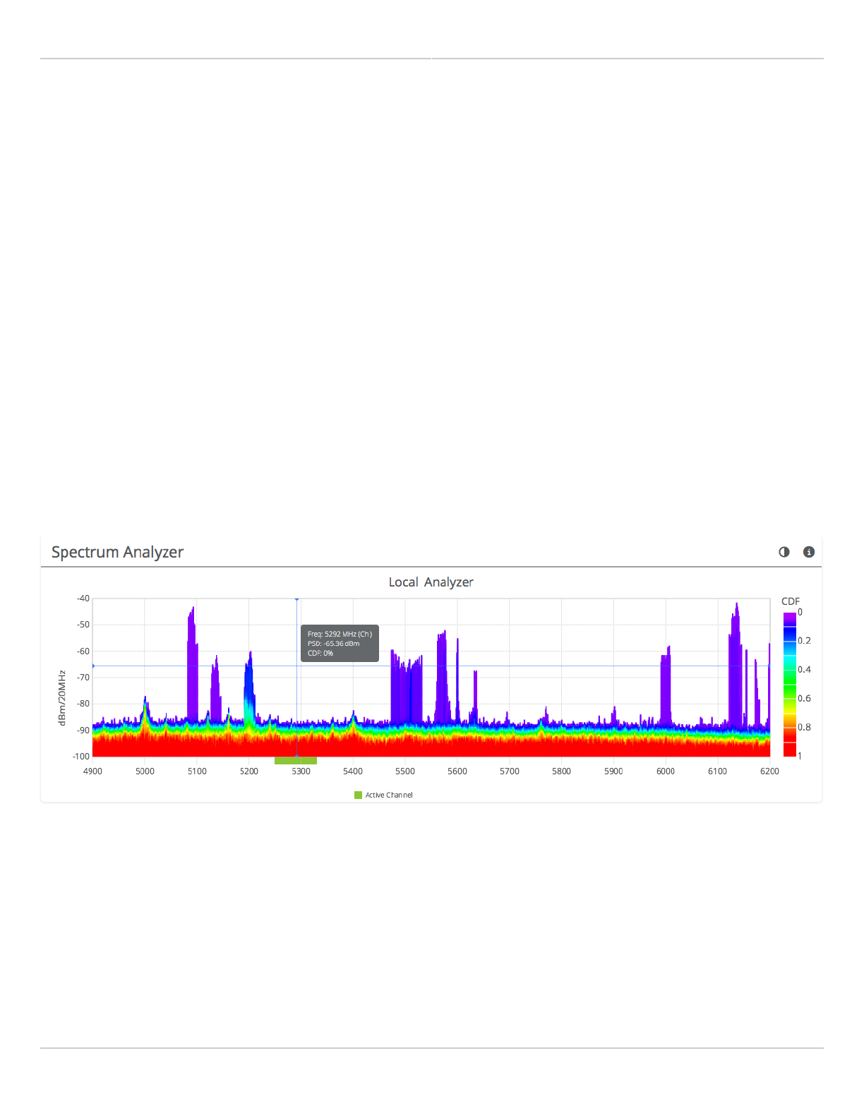
Reading the Spectrum Analyzer
The Spectrum Analyzer actively scans the spectrum in the background to report on interference sources that may
impact link performance. Click on the half circle icon in the upper right to toggle the graph's background color
between black and white.
Channels in use have higher Power Spectral Density (PSD), or amplitude, on the vertical axis, and are shaded in
different colors to represent how often the signals are likely to be on the same frequency at the same amplitude.
The legend to the right of the graph explains the color code for the Cumulative Distribution Function (CDF). The
color red suggests the highest probability (1 = 100%), while purple represents the lowest probability (0 = 0%).
Cross hairs appear on the graph beneath the mouse pointer along with an information box containing the frequency
(channel), PSD, and CDF values.
There are three types of markings, or bars, immediately beneath the graph’s horizontal axis that indicate frequency
ranges that are restricted, manually excluded, or in active use by this link. Note that traffic from the Active Channel
is excluded from the display so that noise can be detected.
Mimosa Client Help Content
Mimosa Clients Channel & Power
Copyright © 2014 Mimosa Page 47
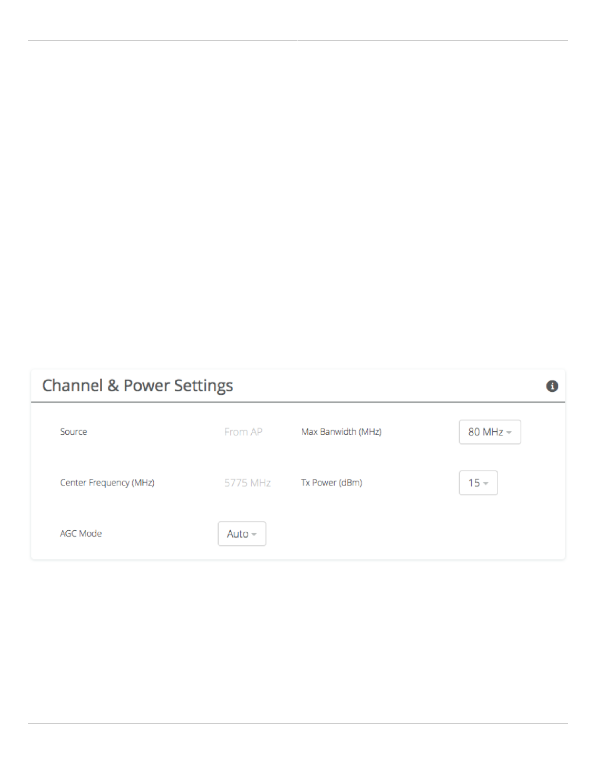
Managing Channel & Power Settings
The Channel and Power Settings panel allows for either automatic or manual changes to frequency, channel width,
and power. When SRS (TDMA) is selected as the Wireless Protocol on the Link page, only the Power Override control
is available.
Source - The values on this page are inherited from the AP through wireless beacons.
●
Max Channel Width (MHz) - Select the maximum channel width (20, 40, or 80 MHz).
●
Center Frequency (MHz) - The center frequency of the channel used on the link. The center frequency
●
represents the absolute center of the selected channel width without any offset, and the center can be moved
in 5 MHz increments. The Channel will be automatically set by the AP, and not editable.
Tx Power (dBm) - Set the desired transmit power level. The allowed options are determined by a combination of
●
country and chosen frequency. If Auto Everything is set to On, the Channel & Tx Power will be automatically set,
and not editable.
Power Override - Allows Tx power changes from the value set by the AP through beacons.
●
AGC Mode - Use this feature to set the signal level below which the radio ignores incoming RF signals. The
●
choices are Off, Auto, or Manual.
AGC Minimum Rx Power (dBm) - In Manual mode, select an Rx power level below your expected signal, but
●
above other interference (-90 to -10 dBm).
Regulatory Domain - The country in which the device has been configured to run.
●
Note: Tx power selections may be limited based on your regulatory domain.
Mimosa Client Help Content
Mimosa Clients Link
Copyright © 2014 Mimosa Page 48
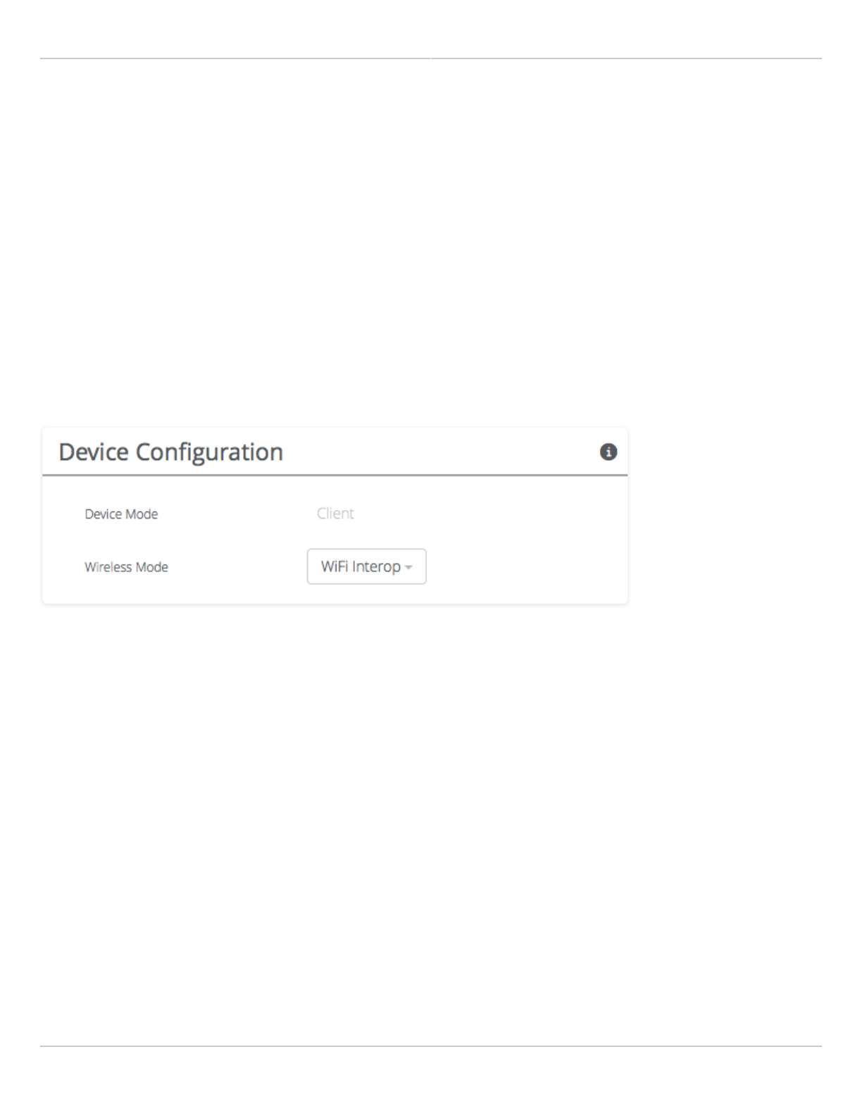
Device Configuration
The Device Configuration panel shows the wireless mode for the device and contains controls to select supported
wireless protocols.
Wireless Mode - The C5 is a client of an Access Point, and this value cannot be changed. The C5c operates as
●
client or station device depending on the selected band. In U-NII-1 and U-NII-4 bands, the C5c is a PTP client
device. In U-NII-2 and U-NII-3 bands, the C5c is a PTMP station device.
Wireless Protocol - Select an option compatible with the Access Point.
●
WiFi Interop (CSMA) - Select for compatibility with newer 3rd party Access Points.
●
SRS (TDMA) - Mimosa proprietary TDMA protocol for fixed Clients.
●
Auto - Follow the Wireless Protocol setting on the AP.
●
Gender - Traffic Split - When GPS-Sync is selected, clients are set to gender B by default, and are configured to
●
allocate bandwidth symmetrically (50/50).
TDMA Window - When GPS-Sync is selected, this value represents the length of the time slot in milliseconds.
●
Mimosa Client Help Content
Mimosa Clients Link
Copyright © 2014 Mimosa Page 49
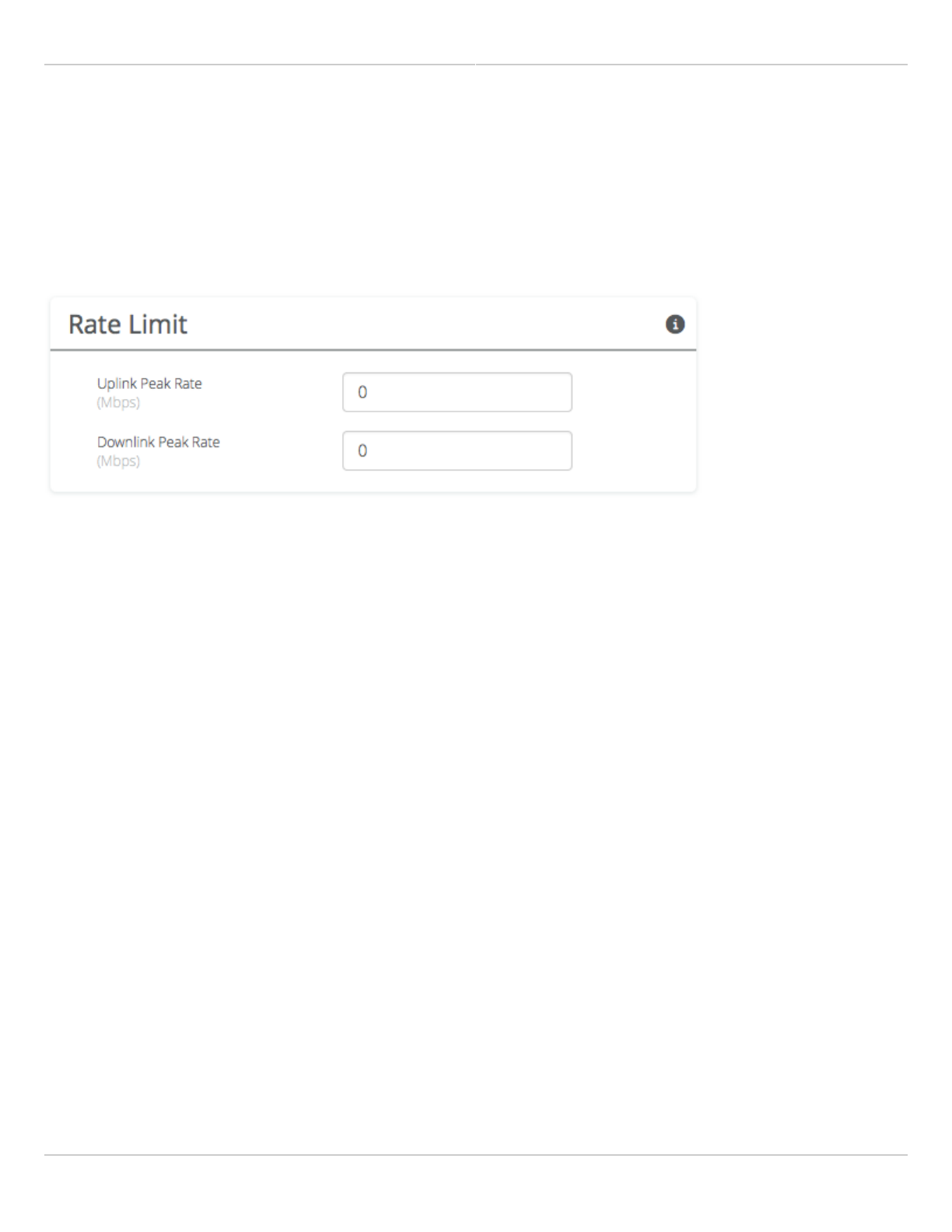
Rate Limit
The Rate Limit panel contains controls to limit upstream and downstream throughput.
Upstream Peak Rate (Mbps) - Enter the maximum throughput allowed for upstream traffic. Enter 0 to remove
●
limits.
Downstream Peak Rate (Mbps) - Enter the maximum throughput allowed for downstream traffic. Enter 0 to
●
remove limits.

Mimosa Client Help Content
Mimosa Clients Link
Copyright © 2014 Mimosa Page 50
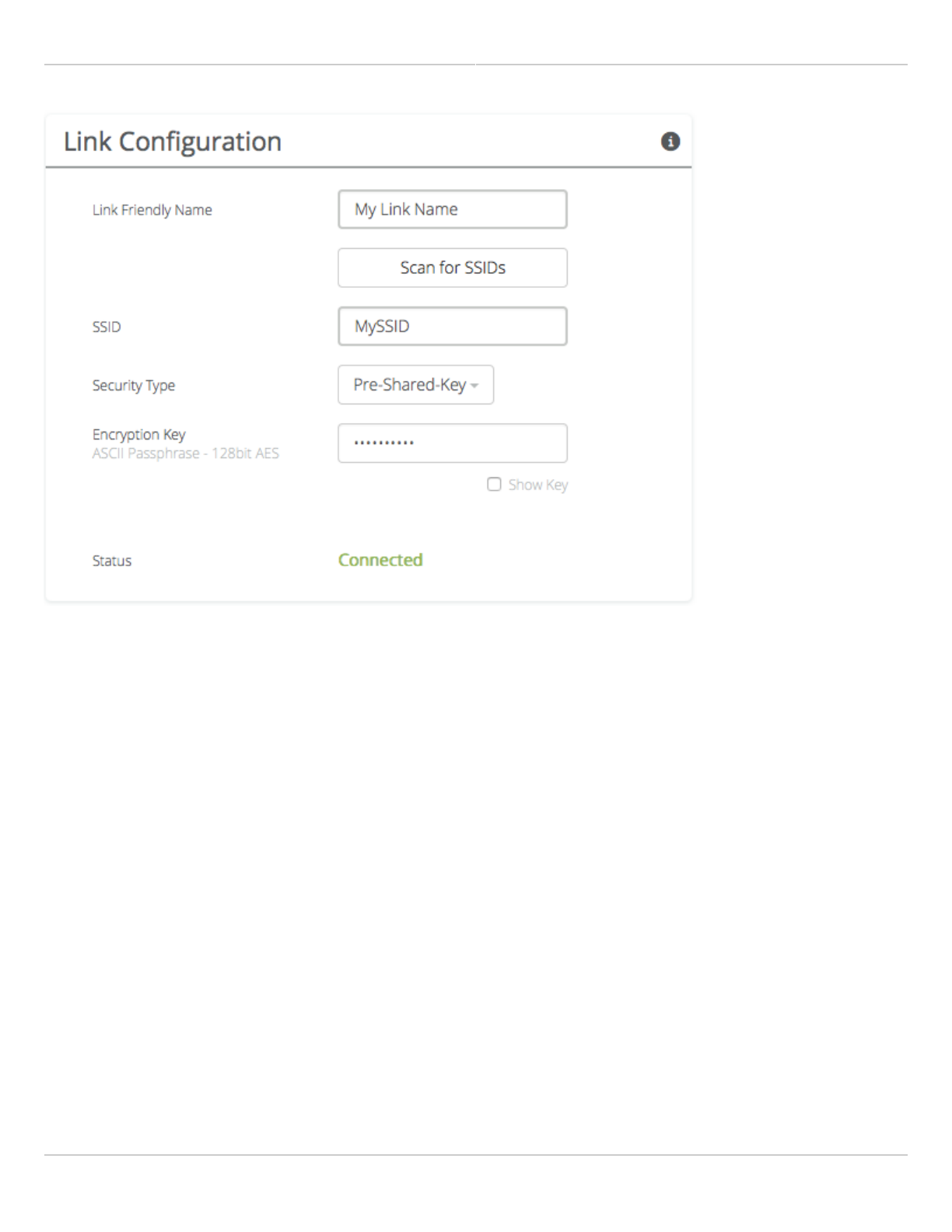
Link Configuration Settings
The Link Configuration panel includes controls to define the 5 GHz SSID and passphrase between radios:
Link Friendly Name - A friendly name to describe the link between the Access Point (AP) and Client/Station. This
●
name is used to differentiate amongst other links.
Scan for SSID - Click this button to display a list of Access Point SSIDs.
●
SSID - The wireless link name used by both radios. Both AP and Station must use the same SSID to associate
●
with each other.
Security Type - Select from the following security options:
●
Open - No authentication or encryption is used. This operational mode is not secure.
●
Pre-Shared Key - There is no user authentication but the link is encrypted using a pre-shared key.
●
Encryption Key - Enter the ASCII Passphrase to connect with the broadcasted SSID. Select "Show Key" to
●
see passphrase in plain text. Enter any combination of printable characters. The passphrase should be
between 8 to 63 characters in length. The Encryption Key must be the same on both the Access Point and
Station for them to communicate with each other.
Enterprise - Users are authenticated and encrypted using radius.
●
Username - This field is shown if the Enterprise option is selected in the Security field. Enter the username
●
for the authentication server.
Password - This field is shown if the Enterprise option is selected in the Security field. Enter the password
●
for the authentication server.
Status - Indicates whether the AP and Station are "Connected" (associated) or "Not Connected" (disassociated).
●
Please ensure that the SSID, Encryption Key, and firmware versions are the same. Additionally, ensure that the IP
addresses are different, and on the same subnet.
Mimosa Client Help Content
Mimosa Clients Link
Copyright © 2014 Mimosa Page 51
Mimosa Client Help Content
Mimosa Clients Location
Copyright © 2014 Mimosa Page 52
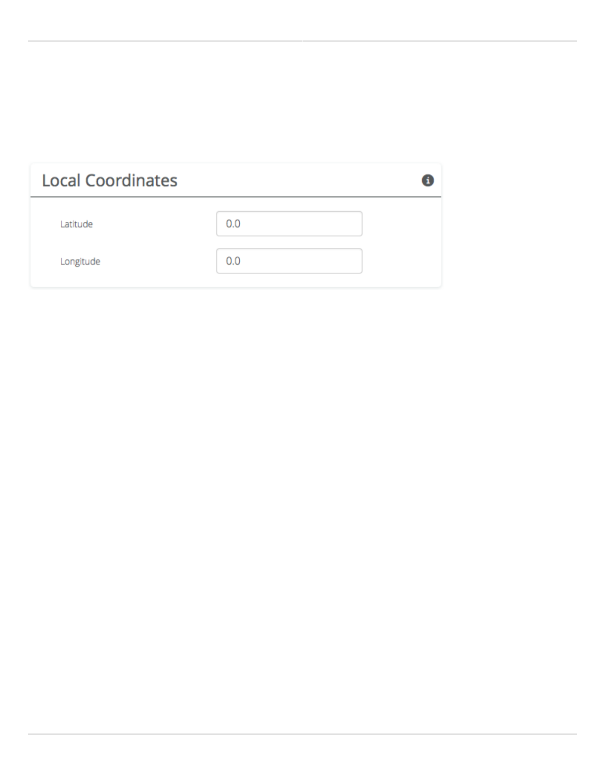
Local Coordinates
Enter the latitude and longitude of the local radio in signed decimal degrees with four digits after the decimal point
(e.g. ##.####). These values are used to display the radio on a map within Mimosa cloud applications.
Mimosa Client Help Content
Mimosa Clients Location
Copyright © 2014 Mimosa Page 53
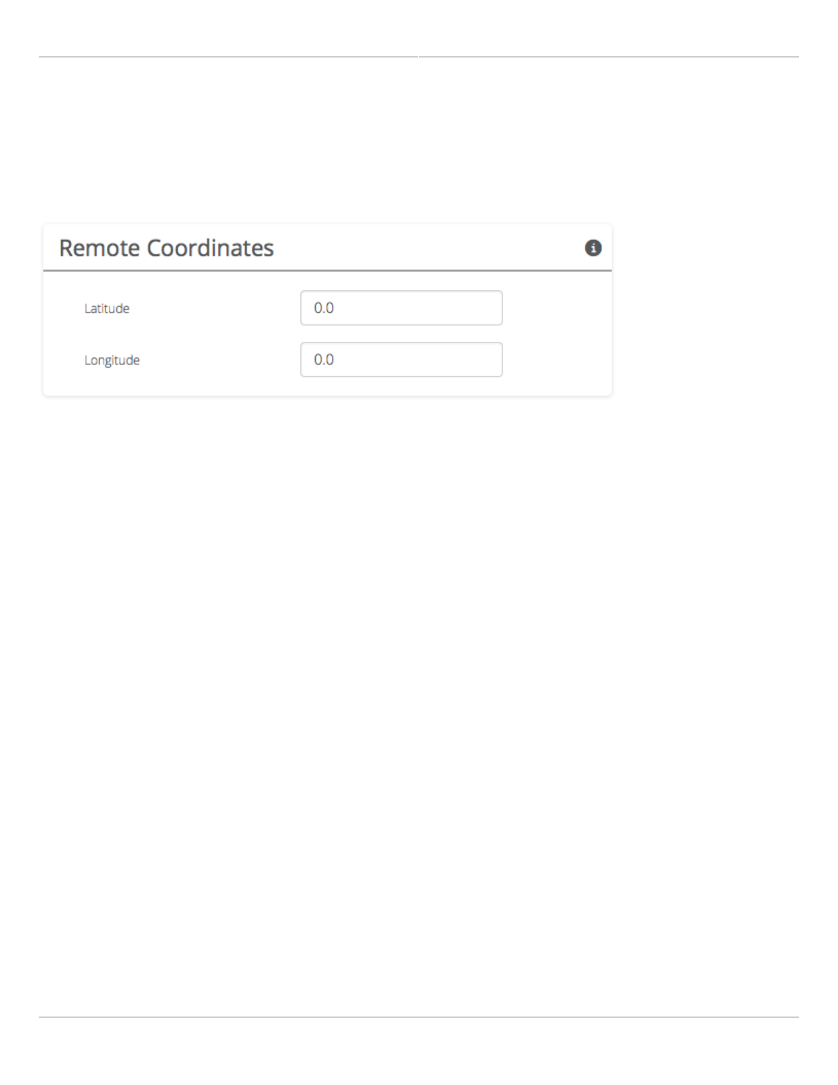
Remote Coordinates
Enter the latitude and longitude of the remote radio in signed decimal degrees with four digits after the decimal
point (e.g. ##.####). These values are used to display the radio on a map within Mimosa cloud applications.
Mimosa Client Help Content
Mimosa Clients Location
Copyright © 2014 Mimosa Page 54
Distance
The calculated distance between radios based on the local and remote coordinates.
Mimosa Client Help Content
Mimosa Clients Site Survey
Copyright © 2014 Mimosa Page 55
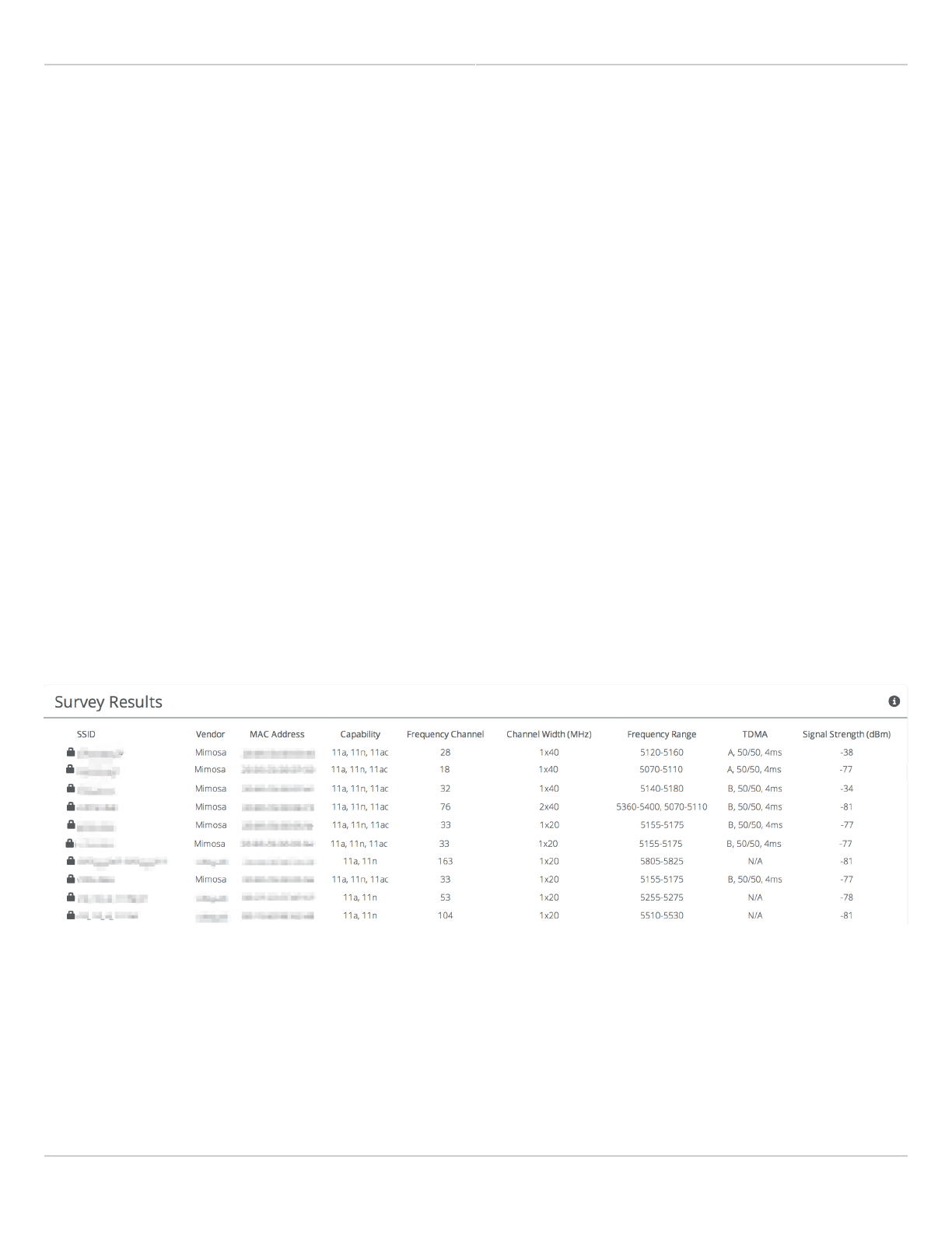
Reading Site Survey Results
The Survey Results status table summarizes the results of a site survey, including the SSIDs broadcast by other
devices, their configuration and capabilities. Note that the Site Survey function is only available on radios configured
as a Station (versus AP).
The table provides the following data per device found:
SSID - The wireless link name advertised by each detected AP.
●
Vendor - The name of the device manufacturer (if known).
●
MAC Address - The device's unique identifier.
●
Capability - Indicates which 802.11 (Wi-Fi technology standard) is support by the device. Options include A, G,
●
N, AC.
Frequency Channel - Lists the channel on which the device operates.
●
Channel Width (MHz) - The size of the channel on which the device operates.
●
Frequency Range - The specific frequency range (in MHz) within the channel that the device operates.
●
GPS-Sync - Displays the TDMA settings for Mimosa radios.
●
Signal Strength (dBm) - The received power level (in dBm) from each detected AP.
●
Note: The Site Survey will temporarily interrupt your link. Once started, this process cannot be stopped until
complete.
Use the Start Survey button to place the radio into the scan mode to search for 802.11-compatible access points.
The Last Updated field indicates (down to the second) when the last Site Survey was requested.
It is important to note that running a site survey will temporarily take down your link. Once activated, this process
cannot be stopped until complete. Please plan accordingly.
Mimosa Client Help Content
Mimosa Clients General
Copyright © 2014 Mimosa Page 56
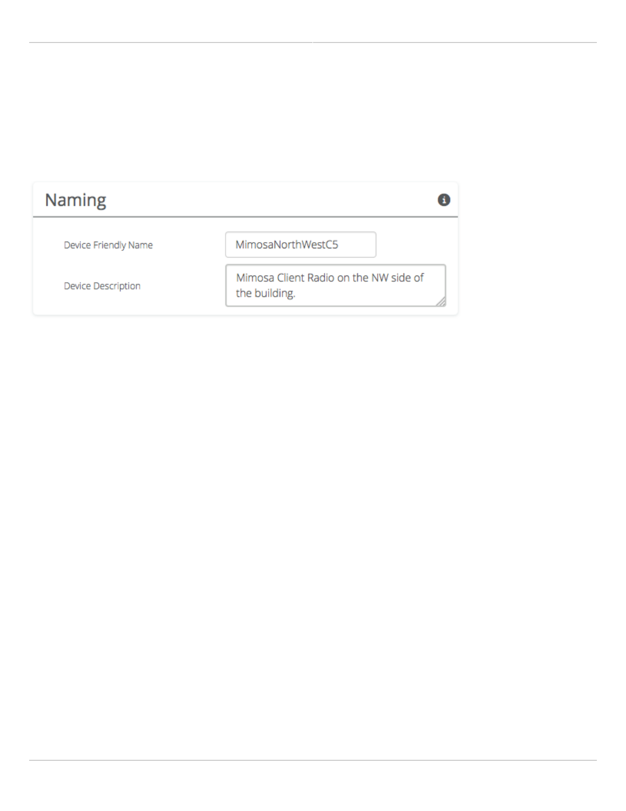
Setting a Device Name and Description
The device name and description are local identifiers for administrative purposes, and are not used as part of the
wireless link.
Device Friendly Name - Name for the local device displayed on the Dashboard.
●
Device Description - A more detailed device description (up to 150 characters) for administrative purposes.
●
Mimosa Client Help Content
Mimosa Clients General
Copyright © 2014 Mimosa Page 57
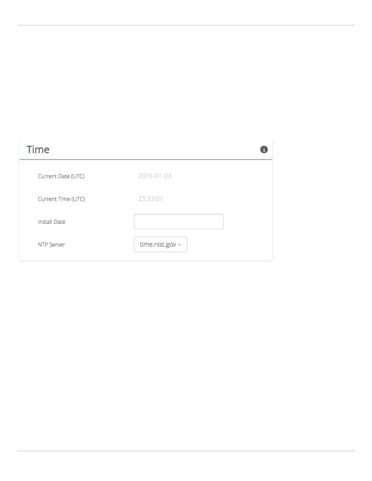
Reading the Date/Time & Setting the Install Date
The Time panel shows the current date and time in Coordinated Universal Time (UTC). The Install Date input box can
be used for administrative purposes, but it is optional and has no other effect.
Current Date (UTC) - Current date as set by the NTP Server
●
Current Time (UTC) - Current time as set by the NTP Server
●
Install Date - Used to track the date that the device was installed
●
NTP Server - Domain name or IP address of network time server
●
Mimosa Client Help Content
Mimosa Clients General
Copyright © 2014 Mimosa Page 58
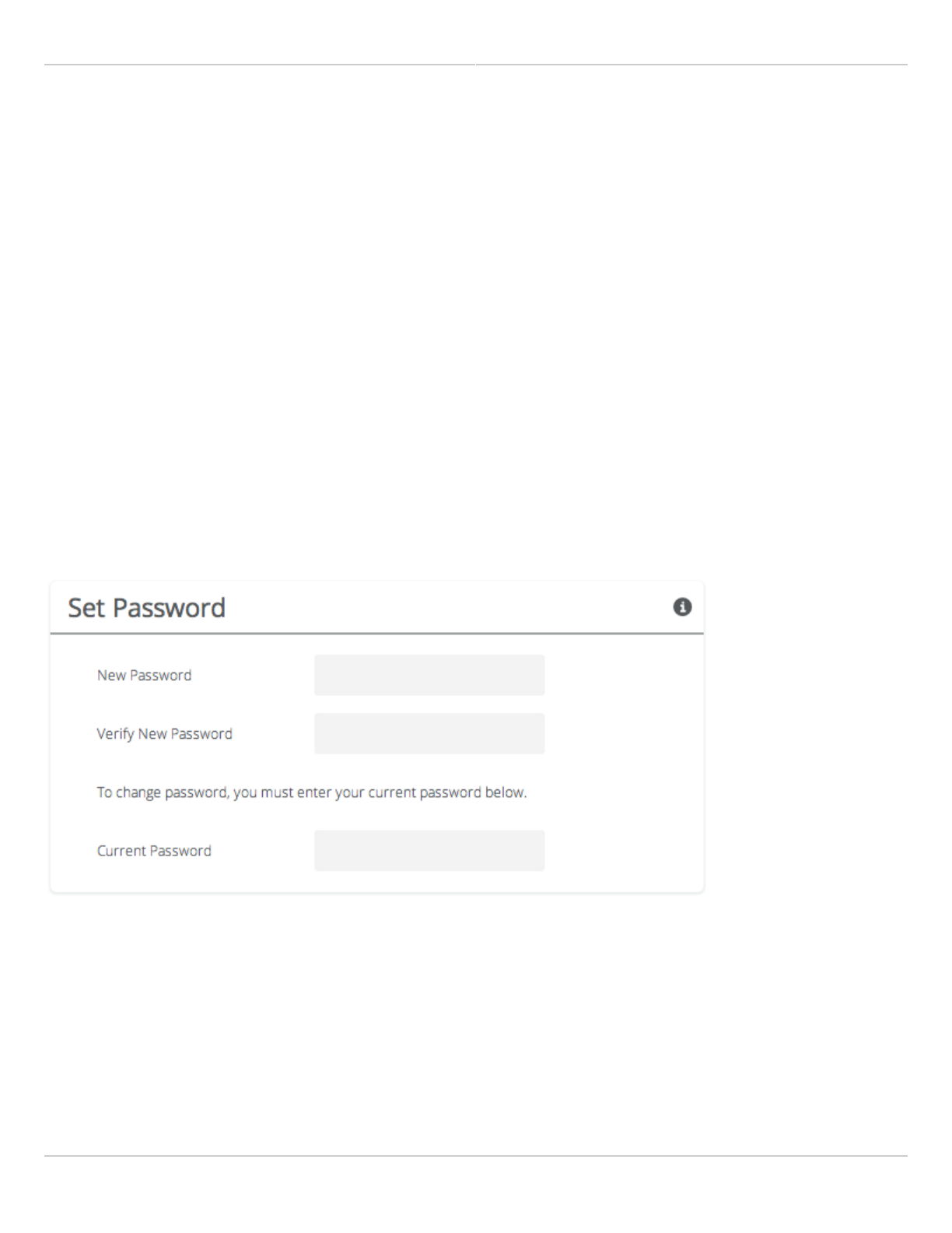
Setting a Password
Enter the new password in both the New Password and Verify New Password input boxes to validate that they were
typed correctly. To finalize the change, enter the existing password and then save. The default password should be
changed during device configuration to protect your network.
New Password - Enter the new password.
●
Verify New Password - Re-enter the new password (to confirm).
●
Current Password - Enter the existing password (as a security measure).
●
The password validation rules are as follows:
It must be between 6 to 64 characters.
●
It can use capital (A-Z) or lower case (a-z) characters, excluding space.
●
Valid special characters for the password include ! " # $ % & ' ( ) * + , - . / : ; < = > ? [ ] ^ _ ` { | } ~
●
The password cannot be blank.
●
The password may not have a leading or trailing space.
●
There is no complexity required for the password.
●

Mimosa Client Help Content
Mimosa Clients General
Copyright © 2014 Mimosa Page 59
General Miscellaneous Settings
The Miscellaneous panel contains general functionality not described elsewhere.
Unlock Code - Displays the code used to unlock the device.
●
Mimosa Client Help Content
Mimosa Clients Management
Copyright © 2014 Mimosa Page 60
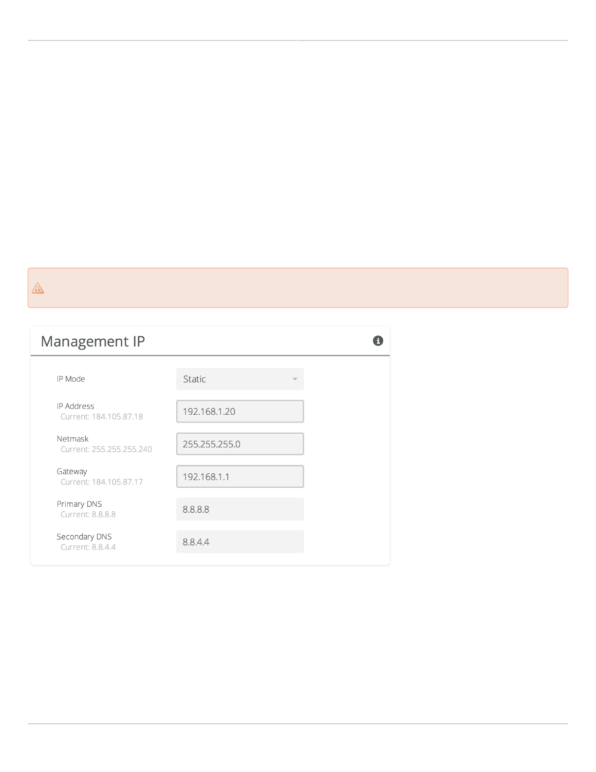
Setting the Management IP Address
The Management IP panel contains controls for setting the device's network address, subnet, gateway and DNS
servers.
IP Mode - Select the preferred mode of network addressing: Static or DHCP+Static Failover. If Static is chosen,
●
the device will always use the IP address that has been assigned. If DHCP+Static Failover is chosen, and a
DHCP server is available, then the addresses are automatically assigned by the DHCP server. If a DHCP server is
unavailable, the device will use the static IP address listed below.
IP Address - The network address used to manage the device.
●
Netmask - The subnet mask that defines the network subnet.
●
Gateway - The gateway address for the subnet.
●
Primary DNS - The first DNS server IP Address. Default is 8.8.8.8.
●
Secondary DNS - The backup DNS server IP Address. Default is 8
●
Note that the wired Ethernet interface is configured by default to use DHCP with a static failover to the IP
Note that the wired Ethernet interface is configured by default to use DHCP with a static failover to the IP
address in the table below.
address in the table below.
Mimosa Client Help Content
Mimosa Clients Management
Copyright © 2014 Mimosa Page 61
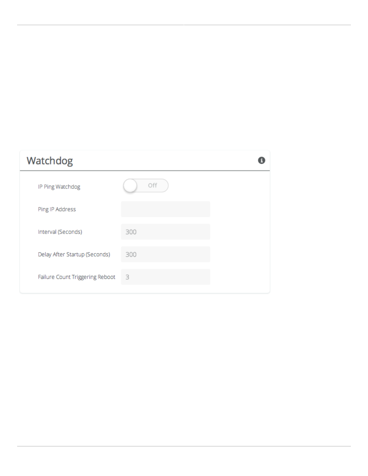
Enabling Watchdog
The Watchdog panel contains controls to monitor a remote host and reboot the local device under configurable
failure conditions.
IP Ping Watchdog - Enables the IP Ping Watchdog feature, which resets the device if it cannot ping a certain IP
●
after a number of retry attempts.
Ping IP Address - Enter the IP address of the device to ping.
●
Interval (Seconds) - Set the number of seconds (1-3600) between ping attempts.
●
Delay After Startup (Seconds) - Set the delay (1-3600) between device start up and the first ping attempt.
●
Failure Count Triggering Reboot - Set the number of failed ping attempts (1-100) before rebooting the device.
●
WARNING: rebooting will take the device offline.
Mimosa Client Help Content
Mimosa Clients Management
Copyright © 2014 Mimosa Page 62
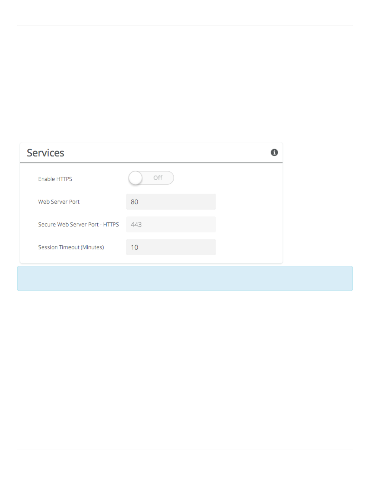
Management Services
The Services panel holds controls to secure management traffic by specifying how it should be served over the
network.
Enable HTTPS - Use SSL to access the web interface of this device.
●
Web Server Port - Indicate which TCP port will be used for the web server. This web server is for the web
●
interface.
Secure Web Server Port - Indicate which TCP port will be used for the secure web server.
●
Session Timeout - Set the number of minutes (0-60) of inactivity that will be allowed on the interface before
●
automatic log-out for sessions. If set to "0", the session will have no timeout.
Following an automatic session timeout, logging back into the device will take you to the Dashboard
Following an automatic session timeout, logging back into the device will take you to the Dashboard
screen.
screen.
Mimosa Client Help Content
Mimosa Clients Management
Copyright © 2014 Mimosa Page 63
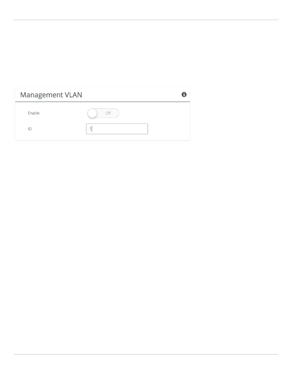
VLAN Management
The VLAN Management panel allows the administrator to enable a VLAN (Virtual Local Area Network) for
management traffic. When enabled, all Web Management traffic must originate from a device on that VLAN.
Enable - Use the slider control to turn VLAN Management on or off.
●
ID - The VLAN ID tag.
●
Mimosa Client Help Content
Mimosa Clients Management
Copyright © 2014 Mimosa Page 64
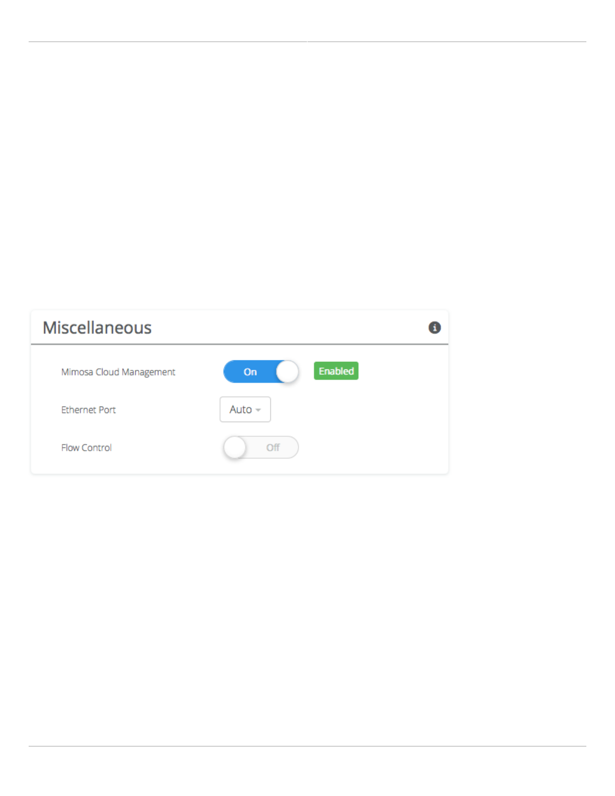
Management Miscellaneous Settings
The Miscellaneous panel contains controls to enable Mimosa Cloud Management and to select the Ethernet Port data
rate, either automatically or manually.
Mimosa Cloud Management - Enables the device to use Mimosa Cloud Management tools. Data will be collected
●
and stored the Mimosa Cloud.
Ethernet Port - Set the Ethernet port transfer rate or allow it to be automatically determined. Manually
●
selectable options are 10, 100, or 1000BaseT at either full or half duplex. Note that Auto or 1000BaseT/Full is
recommended so that the Ethernet port does not create a bottleneck.
Autoneg Mode - Select an autonegotiation mode for Ethernet: Auto, Manual Slave, Manual Master, Preferred
●
Slave, Preferred Master. Auto mode is recommended. Manual options may improve interoperability with some
routers and switches.
Flow Control - Enables PAUSE frames (part of 802.3x standard) to manage the transmission rate between
●
upstream senders and the Ethernet Interface.

Mimosa Client Help Content
Mimosa Clients Notifications
Copyright © 2014 Mimosa Page 65
Enabling SNMP Notifications
Enable the SNMP service to allow SNMP requests and enable push notifications to a remote server.
SNMP - Enable or disable SNMP service on the local device.
●
SNMP Community String - Enter a string for use during client authentication.
●
Contact - Specify an (optional) administrative contact for the SNMP system.
●
Location - Specify the (optional) physical location for the SNMP system.
●
Trap Server - Define the server to receive the notifications.
●
Related:
SNMP Usage Examples: Get / Walk / Table - Sample commands for retrieving values
SNMP Object Names - Query values using SNMP Object Names defined within the Mimosa MIB file
SNMP Traps - Configure outgoing notifications for specific events
SNMP MIB Download - Available values in standard Management Information Base (MIB) format
SNMP OID Reference - Summarized list of available values and where to find them on the GUI
Mimosa Client Help Content
Mimosa Clients Notifications
Copyright © 2014 Mimosa Page 66
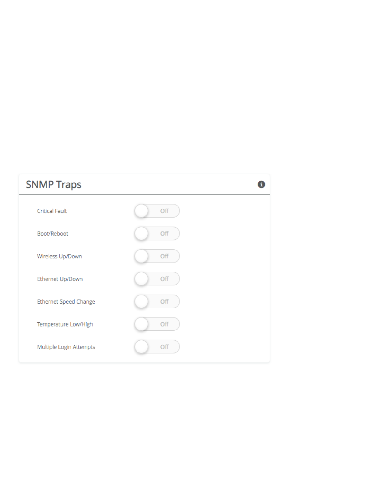
Configuring SNMP Traps
Define which traps (or notifications) are sent to the remote SNMP server.
Critical Fault - Notification created if the device is forced to reboot.
●
Boot/Reboot - Notification created if the system boots or reboots.
●
Wireless Up/Down - Notification created if the device connects to (Wireless Up) or disconnects from (Wireless
●
Down) another device.
Ethernet Up/Down - Notification created if the Ethernet Port is connected (Ethernet Up) or disconnected
●
(Ethernet Down).
Ethernet Speed Change - Notification created when the Ethernet port changes from one speed (10, 100, or
●
1000BaseT) to another.
Temperature Low/High - Notification created if the temperature falls outside of the safe range for the product.
●
Multiple Login Attempts - Notification created if multiple failed login attempts are made from the same IP
●
Address.
Related:
SNMP Usage Examples: Get / Walk / Table - Sample commands for retrieving values
SNMP Object Names - Query values using SNMP Object Names defined within the Mimosa MIB file
SNMP Notifications - Enabling SNMP on Mimosa products
SNMP MIB Download - Available values in standard Management Information Base (MIB) format

Mimosa Client Help Content
Mimosa Clients Notifications
Copyright © 2014 Mimosa Page 67
SNMP OID Reference - Summarized list of available values and where to find them on the GUI
Mimosa Client Help Content
Mimosa Clients Notifications
Copyright © 2014 Mimosa Page 68
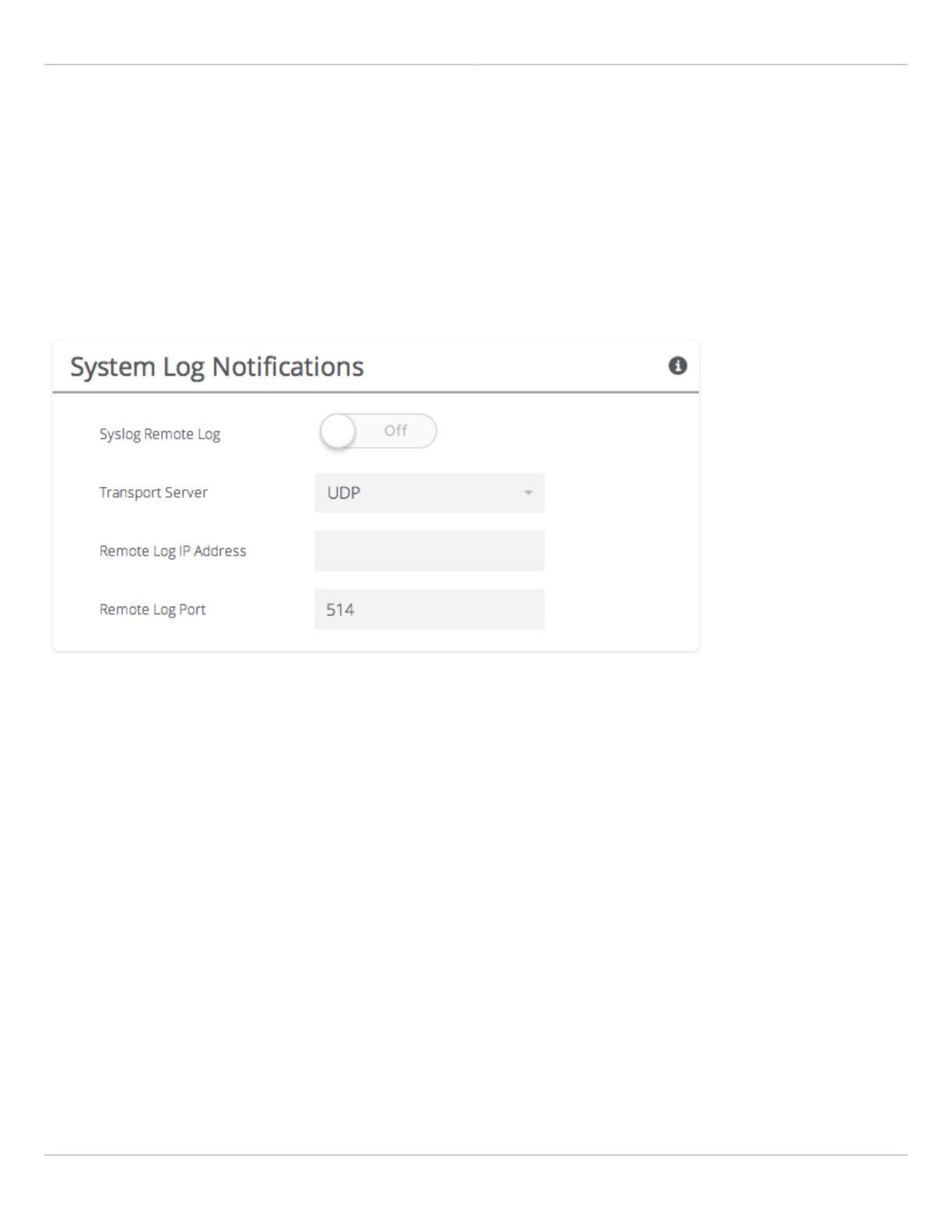
Enabling System Log Notifications
Enable Syslog service on the local device to send traps to a remote Syslog server.
Syslog Remote Log - Enable or disable Syslog service on the local device.
●
Transport Protocol - Choose the desired protocol for the Syslog connection. Note that most devices send UDP
●
messages by default. UDP is an unreliable transmission protocol, thus messages may get lost. Choose TCP for
higher reliability if any message loss is unacceptable.
Remote Log IP Address - List the IP Address of the remote Syslog server to which Notifications will be sent.
●
Remote Log Port - List the Port on the remote Syslog server to which Notifications will be sent.
●
Mimosa Client Help Content
Mimosa Clients Notifications
Copyright © 2014 Mimosa Page 69
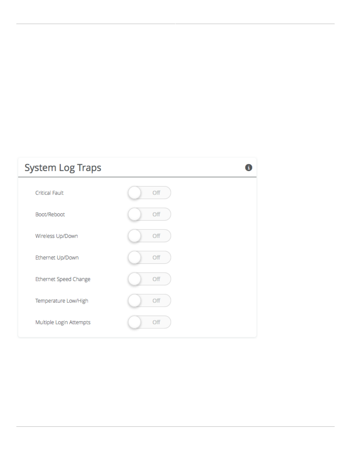
Configuring System Log Traps
Define which traps (or notifications) are sent to the remote server for the System Log.
Critical Fault - Notification created if the device is forced to reboot.
●
Boot/Reboot - Notification created if the system boots or reboots.
●
Wireless Up/Down - Notification created if the device connects to (Wireless Up) or disconnects from (Wireless
●
Down) another device.
Ethernet Up/Down - Notification created if the Ethernet Port is connected (Ethernet Up) or disconnected
●
(Ethernet Down).
Ethernet Speed Change - Notification created when the Ethernet port changes from one speed (10, 100, or
●
1000 BaseT) to another.
Temperature Low/High - Notification created if the temperature falls outside of the safe range for the product.
●
Multiple Login Attempts - Notification created if multiple login attempts are made from the same IP Address.
●
Mimosa Client Help Content
Mimosa Clients Firmware & Reset
Copyright © 2014 Mimosa Page 70
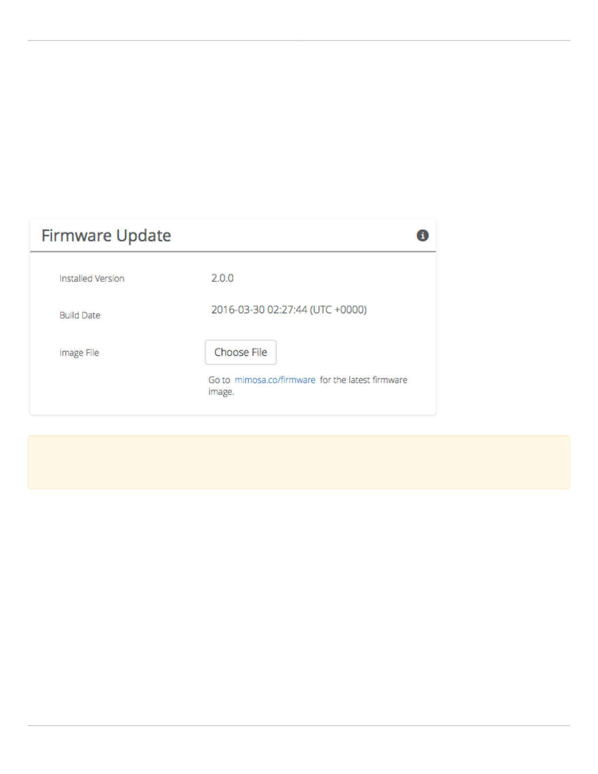
Performing a Firmware Update
The Firmware Update panel displays the current firmware version and date, and allows the user to upload a new
firmware image. The latest firmware image may be downloaded http://mimosa.co/firmware. Alternately, firmware
can be pushed to the device automatically through the Manage application at manage.mimosa.co.
Installed Version - The currently installed firmware version.
●
Build Date - The date that the installed firmware was created.
●
Image File - Update to the latest firmware. Click the Choose File button to select a file for upload the file.
●
When performing a Firmware upgrade, it is advisable to reboot and then upgrade the remote side of the
When performing a Firmware upgrade, it is advisable to reboot and then upgrade the remote side of the
link before the local side. If there is a problem during the upgrade you will still have access to one of the
link before the local side. If there is a problem during the upgrade you will still have access to one of the
radios within the link and can manage the link details.
radios within the link and can manage the link details.
The firmware update process occurs in three phases:
Upload - Selecting a firmware image and uploading to the radio1.
Verification and upgrade - Ensuring that the firmware image is complete and without errors, and then writing2.
to flash memory
Reboot - Restarting with the new firmware image (~90 seconds)3.
The Mimosa Manage application offers a parallel upgrade feature which sends the firmware image to all connected
C5/C5c clients in batches of 5.
Mimosa Client Help Content
Mimosa Clients Firmware & Reset
Copyright © 2014 Mimosa Page 71
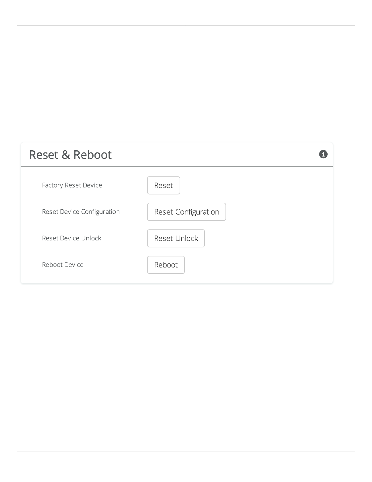
Reset & Reboot the Device
Reboot the device or reset it to its original factory settings.
Factory Reset Device - Clears all configuration settings and locks the device. WARNING: This will delete ALL
●
saved configuration settings and return the device to the locked factory state. You will be required to re-enter
your unlock key upon device reset. The current version of firmware will remain, however.
Reset Device Configuration - Clears all configuration settings. The device will remain unlocked.
●
Reset Device Unlock - Locks the device and resets the country code. WARNING: You will be required to re-enter
●
your unlock key upon reset.
Reboot Device - Restarts the device.
●
Mimosa Client Help Content
Mimosa Clients Backup & Restore
Copyright © 2014 Mimosa Page 72
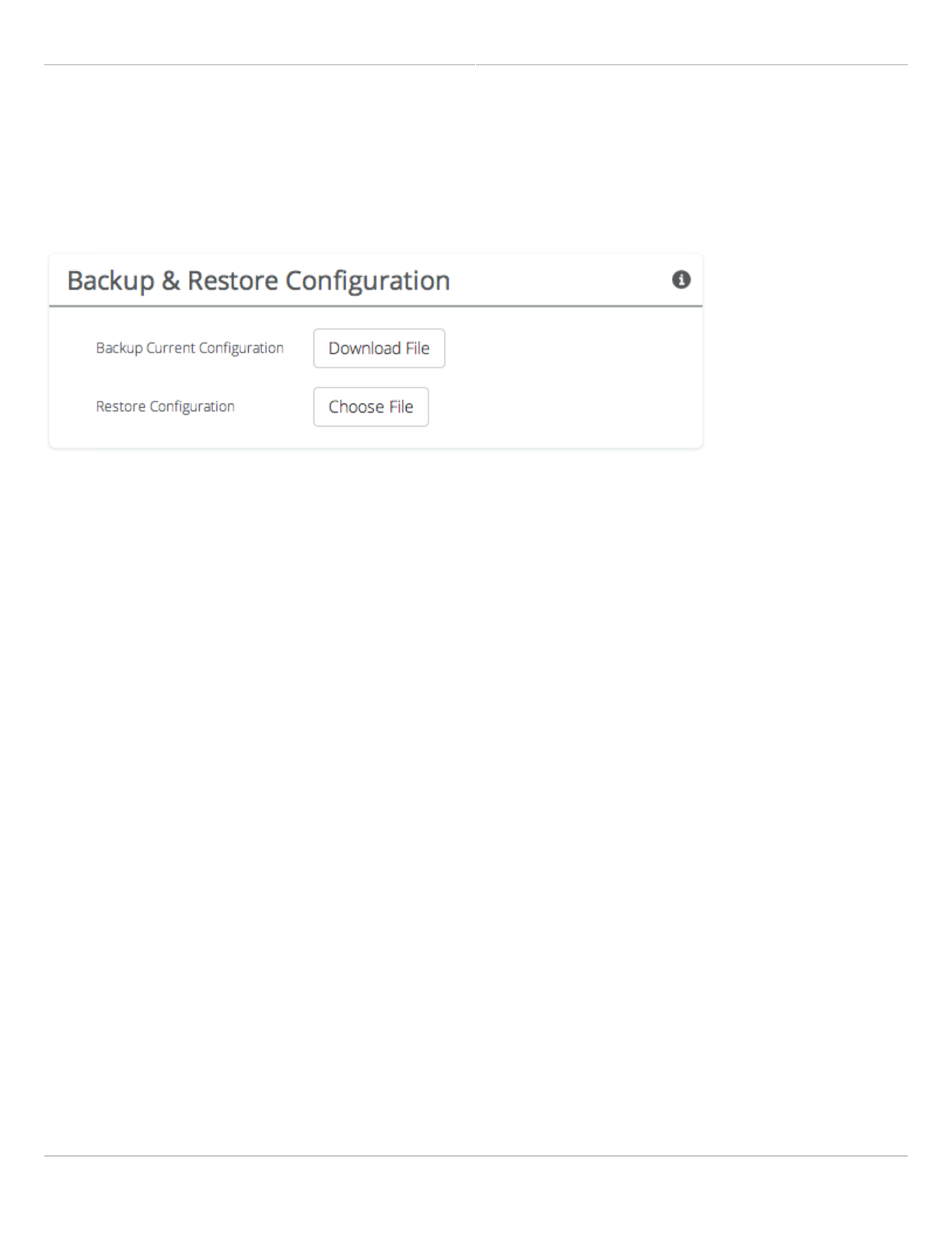
Backup or Restore Configuration Settings
The Backup and Restore Configuration panel contains controls for managing configuration settings files.
Backup Current Configuration - Perform a configuration backup by downloading the mimosa.conf file.
●
Restore Configuration - Click the Choose File button to upload a previously saved mimosa.conf file.
●

Mimosa Client Help Content
Mimosa Clients Tests
Copyright © 2014 Mimosa Page 73
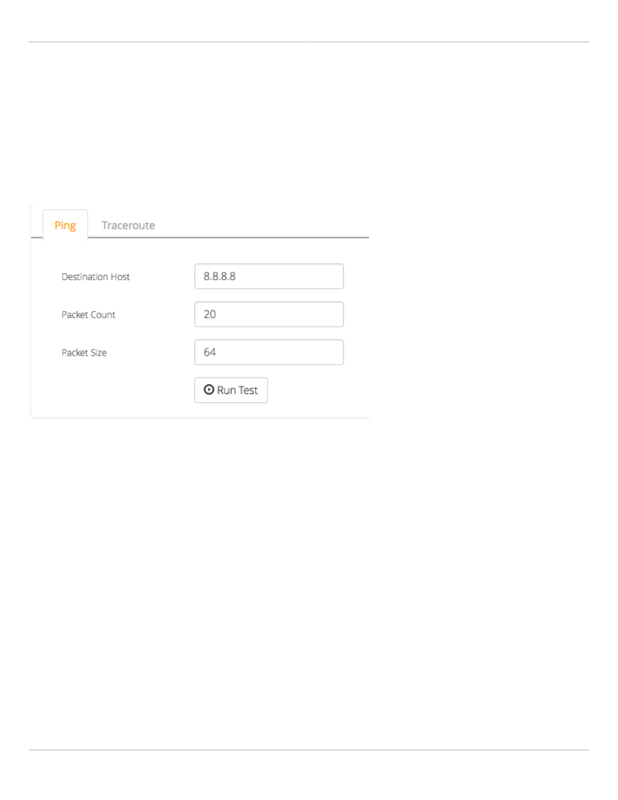
Diagnostic Tests
Three types of tests are available within the Diagnostics section: Ping and Traceroute.
Ping Test
A low level ICMP test which indicates whether the target host is reachable from the local device.
Destination Host - The destination IP Address of the device to ping.
●
Packet Count - The number of packets to transmit during a ping.
●
Packet Size (bytes) - The size of each packet to transmit during a ping.
●
Run Test - Click on the Run Test button to ping the destination IP address. Results are shown in the
●
corresponding table.
Traceroute Test
A network utility used to display the path and transit delay between the local device and a given destination across
an IP network.
Destination Host - The destination IP address for traceroute to send packets.
●
Max Number of Hops - Choose the maximum number of intermediate devices (e.g. routers) through which
●
packets must pass between source and destination.
Run Test - Click on the Run Test button to begin the traceroute test. Results are shown in the corresponding
●
table.
Mimosa Client Help Content
Mimosa Clients Tests
Copyright © 2014 Mimosa Page 74
Running a Ping Test
A low level ICMP test which indicates whether the target host is reachable from the local device.
Destination Host - The destination IP Address of the device to ping.
●
Packet Count - The number of packets to transmit during a ping.
●
Packet Size (bytes) - The size of each packet to transmit during a ping.
●
Run Test - Click on the Run Test button to ping the destination IP address. Results are shown in corresponding
●
table.
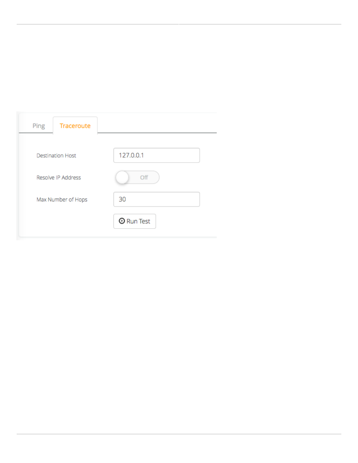
Mimosa Client Help Content
Mimosa Clients Tests
Copyright © 2014 Mimosa Page 75
Running a Traceroute Test
A network utility used to display the path and transit delay between the local device and a given destination across
an IP network.
Destination Host - The destination IP address for traceroute to send packets.
●
Max Number of Hops - Choose the maximum number of intermediate devices (e.g. routers) through which
●
packets must pass between source and destination.
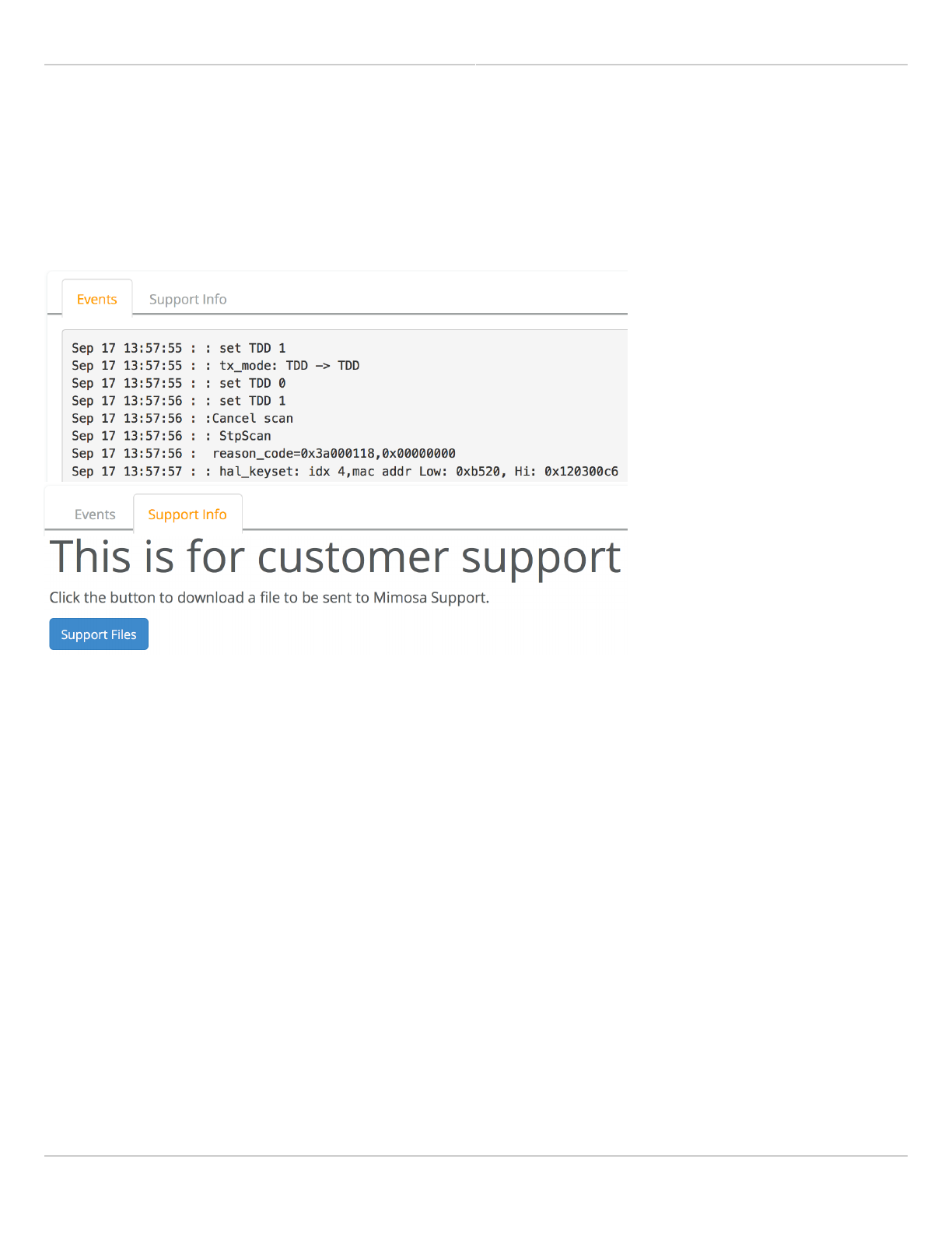
Mimosa Client Help Content
Mimosa Clients Logs
Copyright © 2014 Mimosa Page 76
Diagnostic Logs
View Events and download diagnostic information to share with Mimosa Support.
Event Log - This is a persistent (non-volatile) log of all significant events that occur.
●
Support Info - Download a single file containing all information required by Mimosa Support to help with
●
troubleshooting.

Mimosa Client Help Content
Mimosa Clients SNMP Interface
Copyright © 2014 Mimosa Page 77
SNMP OID Reference
Many SNMP implementations simply provide a MIB which requires a fair amount of study to locate specific values.
We took it a step further and summarized them below for easy reference. Each table shows what values are
available and where to find them within the GUI for comparison.
General Information
OID Object Output Example UI Location
1.3.6.1.4.1.43356.2.1.2.1.1.0 mimosaDeviceName.0 STRING: My C5 AP Preferences > General >
Naming > Device Friendly
Name
1.3.6.1.4.1.43356.2.1.2.1.2.0 mimosaSerialNumber.0 STRING:
1000123456
Overview > Dashboard >
Device Details > Serial
Number (Local)
1.3.6.1.4.1.43356.2.1.2.1.3.0 mimosaFirmwareVersion.0 STRING: 1.2.0 Overview > Dashboard >
Device Details > Firmware
(Local)
1.3.6.1.4.1.43356.2.1.2.1.4.0 mimosaFirmwareBuildDate.0 STRING: 2015-04-
17 18:29:26 (UTC -
0700)
Preferences > Firmware &
Reset > Firmware Update
> Build Date
1.3.6.1.4.1.43356.2.1.2.1.5.0 mimosaLastRebootTime.0 STRING: 2015-04-
18 19:54:42 (UTC
+0000)
Overview > Dashboard >
Device Details > Last
Reboot (Local)
1.3.6.1.4.1.43356.2.1.2.1.6.0 mimosaUnlockCode.0 STRING:
8MEDWLWMN
Preferences > General >
Miscellaneous > Unlock
Code
1.3.6.1.4.1.43356.2.1.2.1.8.0 mimosaInternalTemp.0 INTEGER: 38.2 C Overview > Dashboard >
Device Details > Internal
Temp or CPU Temp (Local)
1.3.6.1.4.1.43356.2.1.2.1.9.0 mimosaRegulatoryDomain.0 STRING: United
States
Wireless > Channel &
Power > Exclusions &
Restrictions > Regulatory
Domain
TDMA Settings
OID Object Output Example UI Location

Mimosa Client Help Content
Mimosa Clients SNMP Interface
Copyright © 2014 Mimosa Page 78
1.3.6.1.4.1.43356.2.1.2.4.1.0 mimosaWirelessMode.0 INTEGER: ap(1) Wireless > Link > TDMA
Configuration > Wireless
Mode
1.3.6.1.4.1.43356.2.1.2.4.2.0 mimosaWirelessProtocol.0 INTEGER: tdma(1) Wireless > Link > TDMA
Configuration > Wireless
Protocol
1.3.6.1.4.1.43356.2.1.2.4.3.0 mimosaTDMAMode.0 INTEGER: A(1) Wireless > Link > TDMA
Configuration > Gender -
Traffic Split
1.3.6.1.4.1.43356.2.1.2.4.4.0 mimosaTDMAWindow.0 INTEGER: 4 ms Wireless > Link > TDMA
Configuration > TDMA
Window
1.3.6.1.4.1.43356.2.1.2.4.5.0 mimosaTrafficSplit.0 INTEGER:
symmetric(1)
Wireless > Link > TDMA
Configuration > Gender -
Traffic Split
Channel & Power Settings
OID Object Output Example UI Location
1.3.6.1.4.1.43356.2.1.2.6.1.7 mimosaTargetSignalStrength INTEGER:
-11.7 dBm
GUI -> Dashboard
1.3.6.1.4.1.43356.2.1.2.6.1.6 mimosaChannelRxPower.1 INTEGER: -15
dBm
Wireless > Channel & Power >
Channel & Power Settings > 5
GHz > Channel Width (MHz)
1.3.6.1.4.1.43356.2.1.2.6.1.5 mimosaChannelTxPower.1 INTEGER: 4.0
dBm
Wireless > Channel & Power >
Channel & Power Settings > 5
GHz > Tx Power (dBm)
1.3.6.1.4.1.43356.2.1.2.6.1.1 mimosaChannelCenterFreq.1 INTEGER: 5500
MHz
Wireless > Channel & Power >
Channel & Power Settings > 5
GHz > Center Frequency (MHz)
Location Information
OID Object Output Example UI Location
1.3.6.1.4.1.43356.2.1.2.2.1.0 mimosaLongitude.0 INTEGER: -121.943684 Wireless > Location > Location
Data > Latitude (Local)
1.3.6.1.4.1.43356.2.1.2.2.2.0 mimosaLatitude.0 INTEGER: 37.28529 Wireless > Location > Location
Data > Longitude (Local)

Mimosa Client Help Content
Mimosa Clients SNMP Interface
Copyright © 2014 Mimosa Page 79
WAN Information
OID Object Output Example UI Location
1.3.6.1.4.1.43356.2.1.2.3.2.0 mimosaWanMac.0 Hex-STRING: 20 B5 C6 00
00 01
Overview > Dashboard >
Device Details > 5 GHz
MAC (Local)
1.3.6.1.4.1.43356.2.1.2.3.3.0 mimosaWanStatus.0 INTEGER: connected(1) Overview > Dashboard >
Wireless Status
1.3.6.1.4.1.43356.2.1.2.3.4.0 mimosaWanUpTime.0 Timeticks: (18571300) 2
days, 3:35:13.00
Overview > Dashboard >
Link Uptime
Performance Information
OID Object Output Example UI Location
1.3.6.1.4.1.43356.2.1.2.7.1.0 mimosaPhyTxRate.0 INTEGER: 940.81
kbps
Overview > Dashboard >
Performance > Throughput > Tx
1.3.6.1.4.1.43356.2.1.2.7.2.0 mimosaPhyRxRate.0 INTEGER: 764.06
kbps
Overview > Dashboard >
Performance > Throughput > Rx
1.3.6.1.4.1.43356.2.1.2.7.3.0 mimosaPerTxRate.0 INTEGER: .27 % Overview > Dashboard >
Performance > PER > Tx
1.3.6.1.4.1.43356.2.1.2.7.4.0 mimosaPerRxRate.0 INTEGER: .73 % Overview > Dashboard >
Performance > PER > Rx
Management Information
OID Object Output Example UI Location
1.3.6.1.4.1.43356.2.1.2.5.8.0 mimosaLocalIpAddr.0 IpAddress:
192.168.1.20
Preferences > Management
> Management IP > IP
Address
1.3.6.1.4.1.43356.2.1.2.5.9.0 mimosaLocalNetMask.0 IpAddress:
255.255.255.0
Preferences > Management
> Management IP >
Netmask
1.3.6.1.4.1.43356.2.1.2.5.10.0 mimosaLocalGateway.0 IpAddress:
192.168.1.1
Preferences > Management
> Management IP >
Gateway

Mimosa Client Help Content
Mimosa Clients SNMP Interface
Copyright © 2014 Mimosa Page 80
1.3.6.1.4.1.43356.2.1.2.5.11.0 mimosaFlowControl.0 INTEGER: disabled(2) Preferences > Management
> Miscellaneous > Flow
Control
Services Information
OID Object Output Example UI Location
1.3.6.1.4.1.43356.2.1.2.8.1.0 mimosaHttpsEnabled.0 INTEGER:
disabled(2)
Preferences >
Management > Services
> Enable HTTPS
1.3.6.1.4.1.43356.2.1.2.8.2.0 mimosaMgmtVlanEnabled.0 INTEGER:
disabled(2)
Preferences >
Management >
Management VLAN >
Enable
1.3.6.1.4.1.43356.2.1.2.8.3.0 mimosaMgmtCloudEnabled.0 INTEGER:
enabled(1)
Preferences >
Management >
Miscellaneous > Mimosa
Cloud Management
1.3.6.1.4.1.43356.2.1.2.8.4.0 mimosaRestMgmtEnabled.0 INTEGER:
enabled(1)
Preferences >
Management > REST
Services > REST
Management
1.3.6.1.4.1.43356.2.1.2.8.5.0 mimosaPingWatchdogEnabled.0 INTEGER:
disabled(2)
Preferences >
Management >
Watchdog > IP Ping
Watchdog
1.3.6.1.4.1.43356.2.1.2.8.6.0 mimosaSyslogEnabled.0 INTEGER:
disabled(2)
Preferences >
Notifications > System
Log Notifications >
Syslog Remote Log
1.3.6.1.4.1.43356.2.1.2.8.7.0 mimosaNtpMode.0 INTEGER:
standard(2)
Preferences > General >
Time > NTP Mode
1.3.6.1.4.1.43356.2.1.2.8.8.0 mimosaNtpServer.0 STRING:
time.nist.gov
Preferences > General >
Time > NTP Server
Related:
SNMP Usage Examples: Get / Walk / Table - Sample commands for retrieving values
SNMP Object Names - Query values using SNMP Object Names defined within the Mimosa MIB file

Mimosa Client Help Content
Mimosa Clients SNMP Interface
Copyright © 2014 Mimosa Page 81
SNMP Notifications - Enabling SNMP on Mimosa products
SNMP Traps - Configure outgoing notifications for specific events
SNMP MIB Download - Available values in standard Management Information Base (MIB) format

Mimosa Client Help Content
Mimosa Clients Troubleshooting Guide
Copyright © 2014 Mimosa Page 82
Troubleshooting Overview
Power / Ethernet
C5 LED Status Indicators
●
Port flapping between 100/1000BaseT
●
Association (Link)
Radios not associated
●
Intermittent Ping/GUI Access
Intermittent Access
●
RF Tuning
High PER
●
Low SNR
●
Low Rx Power
●
Throughput
Low TCP Throughput
●
Reset Procedure
C5
●
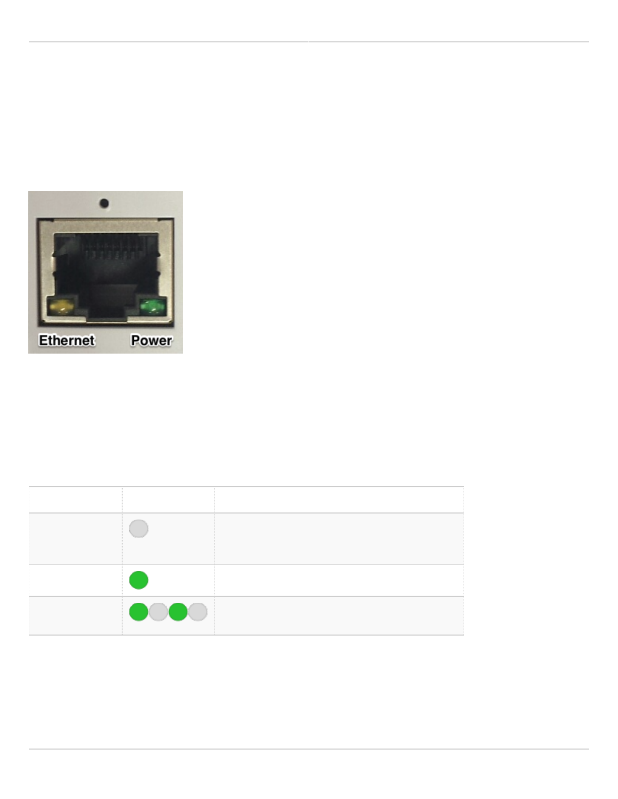
Mimosa Client Help Content
Mimosa Clients Troubleshooting Guide
Copyright © 2014 Mimosa Page 83
LED Status Indicators
Product Applicability: C5, C5c
Two LED indicators are located on the RJ-45 jack to communicate operational status: Ethernet (Yellow) and
Power/Wireless (Green).
The tables below describe the meaning of each LED's state: Off, On (solid), On (blinking), and Color.
Power / Rx Signal Status LED Table
The Power / Rx Signal Status LED indicates the presence of power, and communicates Rx signal strength.
State LED Description
Off No Power to Device / Error1
Note that if the yellow Ethernet Status LED is on,
this does not apply.
Solid Green Power On
Blinking Green Associated; Blink rate proportional to signal
strength2
1 Please check wiring, cycle power, and then contact Mimosa Support if necessary.
2 Ranges from 1 Hz (one blink per second at -90 dBm or less) to 10 Hz (one blink per 100 ms at -50 dBm or greater).
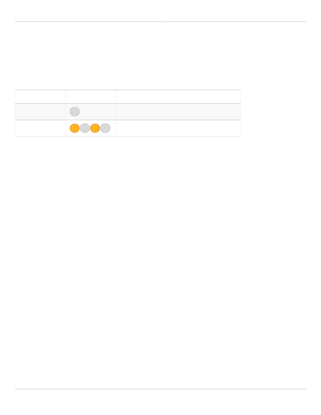
Mimosa Client Help Content
Mimosa Clients Troubleshooting Guide
Copyright © 2014 Mimosa Page 84
Ethernet Status LED Table
The Ethernet Status LED indicates activity for the wired network connection. The device is designed to perform best
with a 1000BASE-T connection. While other port speeds are possible, they are not recommended because they
create a data bottleneck that reduces end-to-end throughput.
State LED Description
Off No Ethernet Connection / No Activity
Blinking Yellow Ethernet Activity

Mimosa Client Help Content
Mimosa Clients Troubleshooting Guide
Copyright © 2014 Mimosa Page 85
Ethernet Troubleshooting
Most Ethernet problems we see are related to cabling. The 1000BaseT standard is far more sensitive to coupled
noise than 100BaseT, which is why we highlight in our documentation that shielded CAT6 is required for reliable
operation. The cable shield should make contact with the metal Ethernet connector, and the metal Ethernet
connector should make contact with the metal PoE receptacle (if applicable).
CAT6 cable is not included with the Mimosa radio since Mimosa does not know the required length for each
installation, and many installers have specific cable brand and type preferences.
No Ethernet
If you are unable to establish an Ethernet connection between the radio and another device, please review the LED
External Status Indicators page.
Port Flapping (alternating between Link Down and Link Up)
Repeated link down and link up messages in the Event Log (Diagnostics > Logs > Events) indicate a power or
cabling problem.
Example Event Log Messages
MIMO_EVENT ethernet link down
MIMO_EVENT ethernet link up (1000/Full)
MIMO_EVENT ethernet link down
MIMO_EVENT ethernet link up (1000/Full)
Troubleshooting Steps:
Ensure that the AC cable is secure at the PoE and AC outlet. If AC power fluctuations are expected, install a1.
UPS with power conditioning to ensure a clean source of power to the PoE.
Ensure that high quality shielded CAT6 cable is installed between the Mimosa PoE and Mimosa radio, and that2.
the total cable length is 100 meters (328 feet) or less. Test continuity of the cable with an Ethernet cable
tester.
If possible, replace the PoE Injector in order to determine if the port flapping issue is with the Radio or the PoE3.
Injector.

Mimosa Client Help Content
Mimosa Clients Troubleshooting Guide
Copyright © 2014 Mimosa Page 86
Port Flapping (alternating between 100BaseT and 1000BaseT)
It is possible for FM interference on a radio tower to couple into the cable on unshielded cable. If the cable shield is
not connected properly on both sides, the shield can act like an antenna and introduce noise into the circuit. Router
firmware incompatibilities can also affect Ethernet negotiation at 1000BaseT.
Example Event Log Messages
MIMO_EVENT ethernet link down
MIMO_EVENT ethernet link up (1000/Full)
MIMO_EVENT ethernet link down
MIMO_EVENT ethernet link up (100/Full)
Troubleshooting Steps:
Ensure that high quality shielded CAT6 cable is installed between the Mimosa PoE and Mimosa radio, and that1.
the total cable length is 100 meters (328 feet) or less.
Ensure that no additional Ethernet surge protection devices are installed between the PoE and Mimosa radio.2.
Protection is already included in the Mimosa Radio and PoE. Additional hardware may increase capacitance
and cause instability.
Ensure that the electrical ground between radio and tower, and the ground from tower to earth have <53.
ohms resistance in total.
Test continuity of the CAT6 cable shield from one end of the cable to the other with a digital multimeter.4.
Ensure that the cable shield makes contact with both the radio's Ethernet input and PoE output connector5.
shells.
Ensure that the IP67 Ethernet gland is installed to prevent moisture from entering the cable.6.
Test cable wiring integrity with an Ethernet cable tester, and/or use a second cable to rule out an internal7.
cable issue.
Ensure that the bend radius of the cable does not exceed the manufacturer's specifications. Sharps bends or8.
kinks can damage the cable or change the isolation between wire pairs within the cable which can degrade
performance.
Repeat the test indoors from router to PoE to the Mimosa radio exhibiting the problem.9.
Test for ground loops indoors by installing an EMI filter and/or non-grounded AC adapter between the PoE10.
power connector and AC receptacle.
Repeat the test indoors from router to PoE to a different Mimosa radio to rule out an Ethernet hardware11.
failure if step above fails.
Connect a laptop with a 1000BaseT Ethernet port to the PoE to determine if the connection rate is dependent12.
upon the connected router. Alternately, connect another switch between the router and PoE

Mimosa Client Help Content
Mimosa Clients Troubleshooting Guide
Copyright © 2014 Mimosa Page 87
Try changing to the same static values on both router and Mimosa radio (e.g. force 100BaseT or 1000BaseT13.
on both sides). The Ethernet port speed setting is located on the Management Miscellaneous Settings page.
If possible, try replacing the PoE Injector in order to determine if the port negotiation issue is with the Radio14.
or the PoE Injector.

Mimosa Client Help Content
Mimosa Clients Troubleshooting Guide
Copyright © 2014 Mimosa Page 88
Troubleshooting Radio Association
Radios may not associate for a number of reasons. Most commonly, because they are configured incorrectly or
because of insufficient SNR.
Note
Note: Mimosa radios must be unlocked before operation. For help with the unlock process, click here.
: Mimosa radios must be unlocked before operation. For help with the unlock process, click here.
Check the Radio Configuration on Both Sides of the Link
Log into the radio GUI and click Wireless > Link.1.
Ensure that the SSID and Encryption Key are the same on both sides of the radio link.2.
Ensure that the same wireless protocol is selected: WiFi Interop or SRS (formerly, GPS-Sync).3.
Ensure that the same firmware is installed on both sides of the radio link.4.
If indoors, point the radios away from each other and turn down the power.
While testing inside a room, point the radios toward the ceiling and set Tx power to the lowest possible1.
setting. This will prevent the receivers from saturating.
Check for interference on the Spectrum Analyzer
Log into the radio GUI and click Wireless > Channel & Power.1.
Look for interference that overlaps the selected center frequencies.2.
If interference is found, there are two options:3.
a) click on the Auto Channel dropdown to enable automatic channel selection and/or channel width
adjustment; or
b) change the channel manually to avoid the interference.
Check for interference on PER Graph
Log in the C5 GUI and click on Overview > Dashboard.1.
On the Performance Graph, click on the navigation circles at the bottom to display "PHY PER".2.
Look for persistent PER above 5%.3.
If PER is greater than 5% for either side of the link, there are two options that you can take at the AP:4.
a) click on the Auto Channel dropdown to enable automatic channel selection and/or channel width
adjustment; or
b) change the channel manually to avoid the noise.

Mimosa Client Help Content
Mimosa Clients Troubleshooting Guide
Copyright © 2014 Mimosa Page 89
Troubleshooting Client DHCP
Client radios may not receive a DHCP IP address for a number of reasons listed below.
Check DHCP Server Reachability
If no clients have DHCP assigned addresses, log into either the A5 or C5 and ping the DHCP server1.
(Diagnostics > Tests > Ping).
If the DHCP server does not respond, proceed to the next step 2.
Check Rogue DHCP Server Protection Settings
Log into the A5 radio GUI and click Preferences > Management.1.
If Rogue DHCP Server Protection is enabled, ensure that your DHCP server IP address is listed. If not, click the2.
plus "+" button to enter it's IP address. If Rogue DHCP Server Protection is not enabled, proceed to the next
step.
Turn on VLAN Passthrough
Log into the A5 radio GUI and click Preferences > Management.1.
If Management VLAN is enabled, ensure that VLAN Passthrough is also enabled.2.
Check the C5 IP Mode settings
Log into the C5 GUI and ensure that the IP mode is set to "DHCP + Static Failover" (Preferences >1.
Management).
Ensure there is no firmware mismatch between A5 and C5
Log into the A5 and C5 individually. Configure your computer to an IP address within the range of the radio's1.
static fallback IP address to access it locally.
Ensure the reported firmware version is the same (Preferences > Firmware & Reset) on both A5 and C5.2.

Mimosa Client Help Content
Mimosa Clients Troubleshooting Guide
Copyright © 2014 Mimosa Page 90
Low Signal-to-Noise Ratio (SNR)
The signal-to-noise ratio (SNR) is the single most important indicator of link health. It represents the magnitude
difference between the Rx power and Rx Noise, which is positively correlated with the modulation coding scheme
(MCS) index. Up to a point, the higher the SNR, the higher the MCS and resulting throughput.
Troubleshooting Steps
Ensure that antennas are optimally aligned to achieve the highest Rx power value across the RF link.1.
Ensure line of site between radios is clear of obstructions that may block the Fresnel zone. Obstructions may2.
cause reflections/refractions that appear as noise.
Choose the clearest RF channel(s) available. Interference (noise) on the same frequency can increase PER3.
because the receiving radio does not have sufficient SNR.
Select narrower channel widths to increase spectral density.4.
Evaluate and adjust the Tx power. Tx power that is too low can result in low SNR, while Tx power that is too5.
high can result in distortion (saturation at the transmitter or receiver). Mimosa recommends setting the Tx
power to the level modeled in the Design application, and then making incremental changes up or down to
determine the optimal level (lowest PER, highest MCS).
Consider installing a higher gain antenna (A5c).6.
Related:
Client Troubleshooting: High PER - Troubleshooting steps for high packet error rate

Mimosa Client Help Content
Mimosa Clients Troubleshooting Guide
Copyright © 2014 Mimosa Page 91
High Packet Error Rate (PER)
The Packet Error Rate (PER) is the number of packets with errors divided by the total number of packets sent within
a 5-second period. Lower values result in higher modulation, while higher values indicate the presence of
interference and result in lower modulation. Tx PER is an indication that the local radio did not receive an ACK from
the remote radio, so is forced to retransmit the same information again. Rx PER is a value sent from the remote
radio to the local radio in management frames.
Mimosa radios reduce the Modulation Coding Scheme (MCS) in response to PER in a process called Rate Adaptation.
PER and MCS are inversely correlated; as PER increases, MCS decreases and vice versa. The effects of this can be
seen on the Dashboard in the form of PHY rate changes. Because data must be retransmitted, time-sensitive
applications such as VoIP data services may be affected by spikes in PER or sustained high PER.
Troubleshooting Steps
Ensure the antennas are optimally aligned to achieve the highest RX power value across the RF link. A low1.
signal-to-noise ratio (SNR) can lead to higher PER.
Ensure line of site between radios is clear of obstructions that may block the Fresnel zone. Obstructions may2.
cause reflections/refractions that appear as noise.
Choose the clearest RF channel available. Interference (noise) on the same frequency can increase PER3.
because the receiving radio does not have sufficient SNR.
Evaluate and adjust the Tx power. Tx power that is too low can result in low SNR, while Tx power that is too4.
high can result in distortion (saturation at the transmitter or receiver). Mimosa recommends setting the Tx
power to the level modeled in the Design application, and then making incremental changes up or down to
determine the optimal level (lowest PER, highest MCS).
Related:
Client Troubleshooting: Low SNR - Troubleshooting steps for low signal-to-noise ratio
Client FAQ: SNR Required for each MCS - Table showing PHY rate per stream based on SNR

Mimosa Client Help Content
Mimosa Clients Troubleshooting Guide
Copyright © 2014 Mimosa Page 92
Low Tx/Rx Power
The Tx/Rx power per chain is shown on the Client List page on the A5, or on the Dashboard of the C5. Although the
A5 transmits on 4 chains to optimize the signal, the C5 will only transmit and receive on a maximum of two chains.
Follow these troubleshooting steps if you observe low Tx/Rx power.
Low power on two chains
Consistent low power across both chains is likely due to long distance or EIRP limitations for selected channels. Use
the Mimosa Design application to model the link for comparison with actual performance. This will help determine if
the observed performance is expected, or if some other problem exists.
Potential solutions include the following:
Aim the antennas to achieve higher signal strength at each receiver
●
Increase Tx Power
●
Select a portion of spectrum that allows higher EIRP limits
●
Select a narrower channel width
●
Select a single channel instead of two channels
●
Install a higher gain antenna (A5c/C5c)
●
Relocate antennas to avoid permanent or temporary physical obstructions impairing the Fresnel zone
●
Low power on one chain
Clients connected to A5-14 may only use a single chain unless they receive strong signals from two of the four A5-
14 antenna panels which are pointed 90 degrees apart.
Clients connected to A5c with a single sector antenna have a better chance of connecting on two chains since all of
the energy is directed in one direction.
Potential solutions include the following:
Design networks where clients are closer in proximity to the AP.
●
Ensure that the client falls within the AP antenna pattern with adequate gain.
●
Related:
Client Troubleshooting: Low SNR - Troubleshooting steps for low signal-to-noise ratio
Client Troubleshooting: High PER - Troubleshooting steps for high packet error rate

Mimosa Client Help Content
Mimosa Clients Troubleshooting Guide
Copyright © 2014 Mimosa Page 93
Troubleshooting Low TCP Throughput
RF Causes
In some cases TCP throughput can be impacted by poor RF conditions (e.g. low SNR, high PER) that lead to higher or
fluctuating latency.
Ethernet Causes
Low TCP throughput can also result from poor conditions on Ethernet either because of coupled noise and/or
insufficient shielding. Please see the Ethernet Speed troubleshooting section for more details.
Third-Party Equipment Causes
Some third-party routers contain native bandwidth tests. Mimosa has found that some router models and firmware
versions are insufficient for testing the full capacity of Mimosa links, leading to skewed results. There are several
reasons including: 100 Mbps port limitations, fixed TCP windows, fixed TCP send and receive buffers, CPU capacity
limitations, etc.
Please refer to the Testing Throughput with iPerf article.
Mimosa Client Help Content
Mimosa Clients Troubleshooting Guide
Copyright © 2014 Mimosa Page 94
Testing Throughput with iPerf
Mimosa has found that iPerf, a tool for active measurements of the maximum achievable bandwidth on IP networks,
provides the most reliable measure of TCP performance. Instructions for downloading iperf, building the executable
for your environment, and usage are available at this link: https://github.com/esnet/iperf
Example Test Topologies
Computer 1 - Mimosa 1 - Mimosa 2 - Computer 2
●
Computer 1 - Switch 1 - Mimosa 1 - Mimosa 2 - Switch 2 - Computer 2
●
Example Commands
The iPerf (version 2) commands below send 10 TCP streams for 100 seconds with 64k TCP window size in one
direction. Open separate terminal windows and reverse the commands to create bidirectional traffic.
Command to make Computer 1 (192.168.1.22) the listener:
iperf -s -f m -i 60
Command to make Computer 2 (192.168.1.23) the sender:
iperf -c 192.168.1.22 -P 10 -t 100 -w 64k
Note: Mimosa radios do not contain iPerf. For accurate measurement, the device under test should not
Note: Mimosa radios do not contain iPerf. For accurate measurement, the device under test should not
generate traffic because the test would impair the ability of the device by occupying the CPU and skewing
generate traffic because the test would impair the ability of the device by occupying the CPU and skewing
the test result. Please see the link below for more information about the Mimosa bandwidth test.
the test result. Please see the link below for more information about the Mimosa bandwidth test.