Minde Electronics Technology CS2X90 Cordless Barcode Scanner User Manual
Shenzhen Minde Electronics Technology LTD. Cordless Barcode Scanner
UserManual.wiki
>
Minde Electronics Technology
>
CS2X90 User Manual
user manual
Navigation menu
Upload a User Manual
Namespaces
Wiki Guide
HTML
PDF
Info
Views
User Manual
Discussion / Help
Navigation
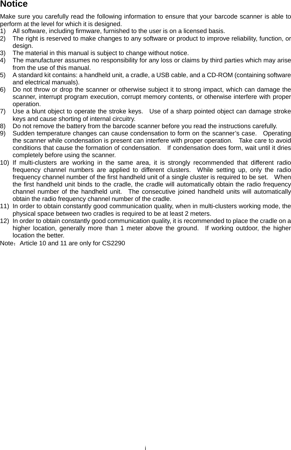
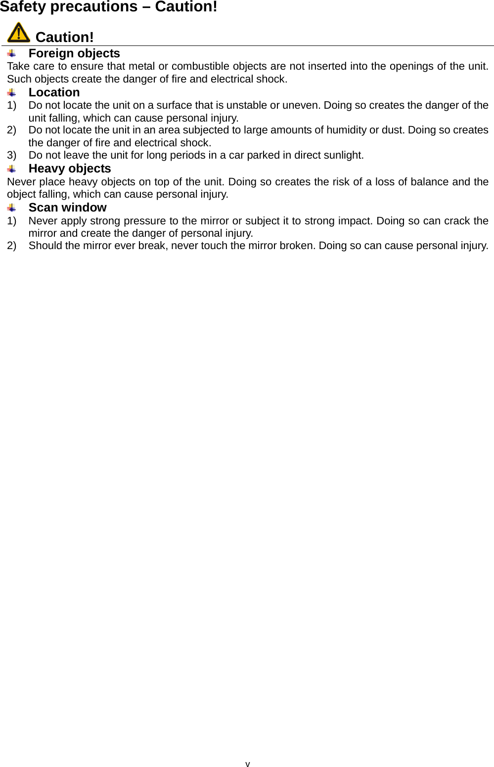
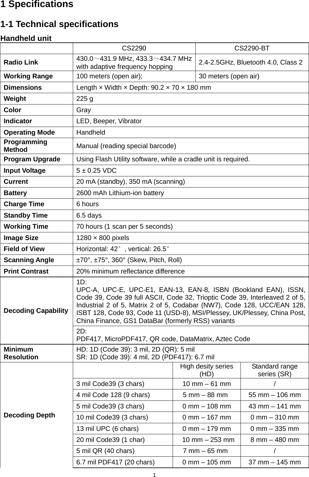
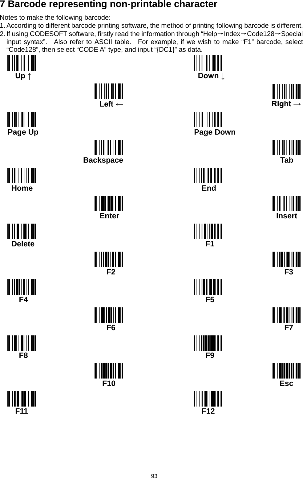
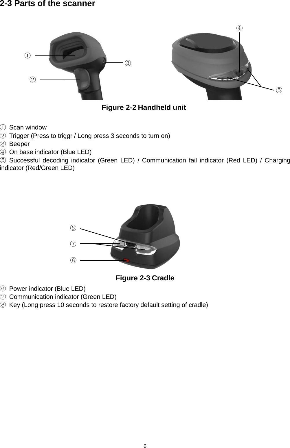
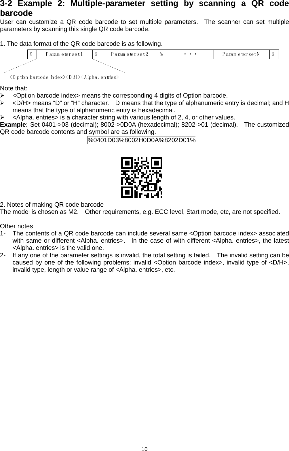
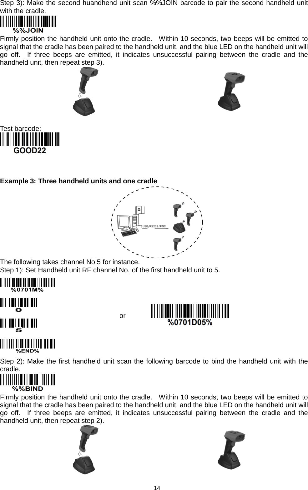
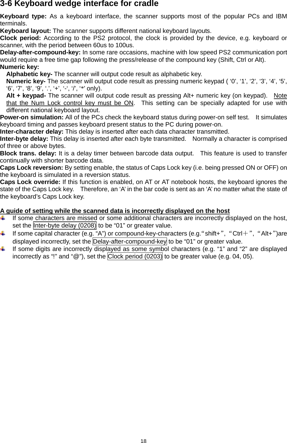
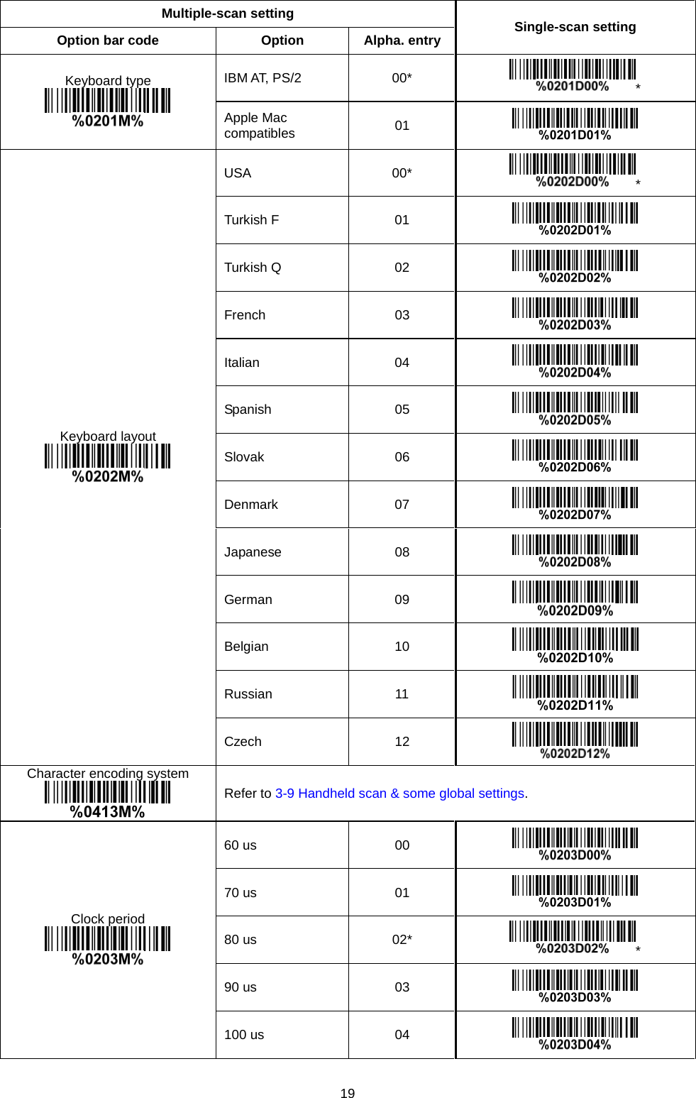
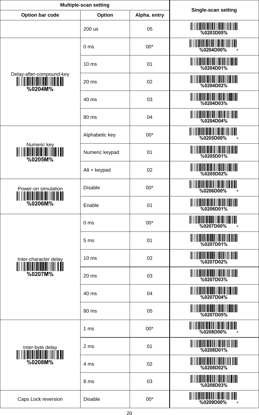
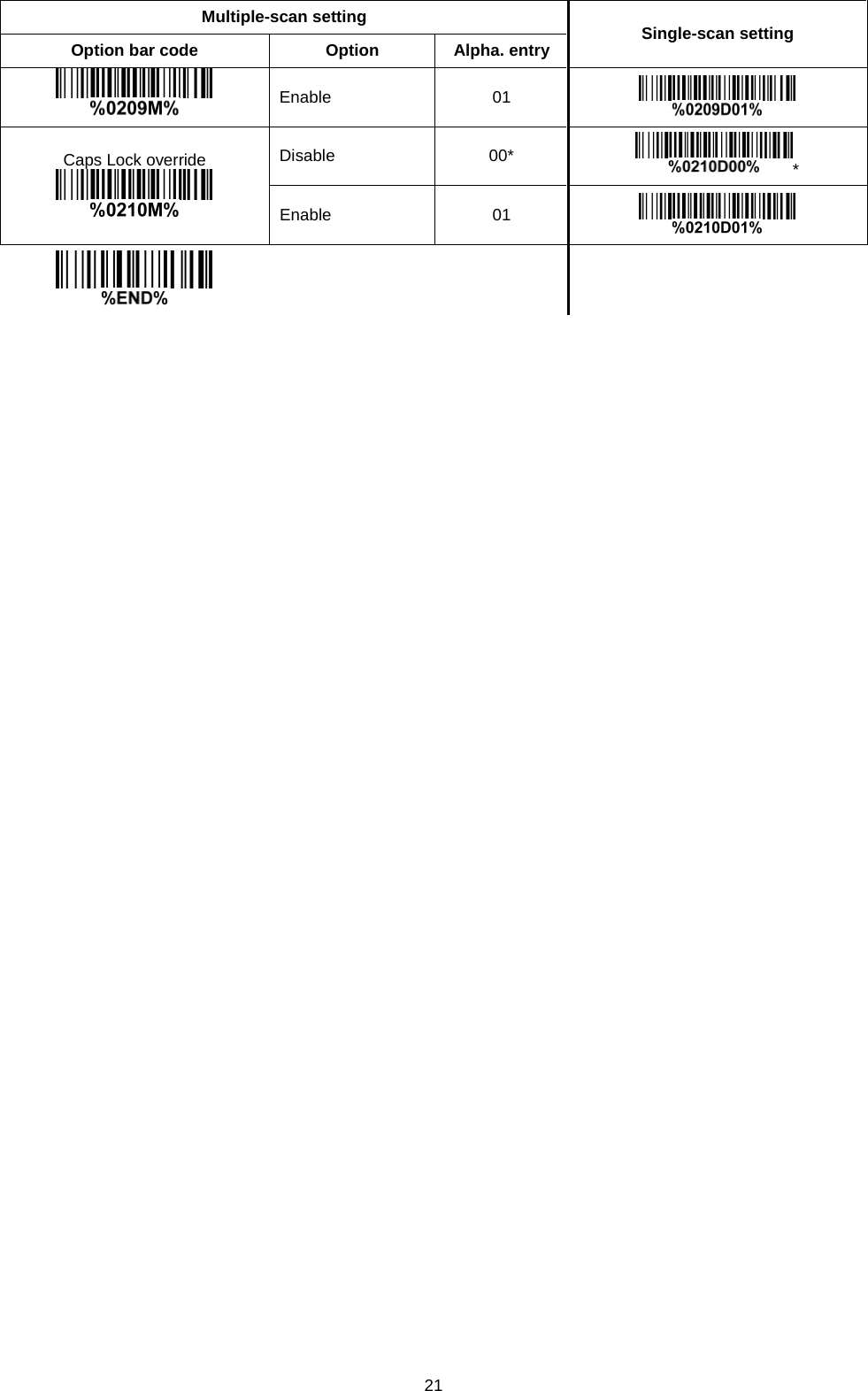
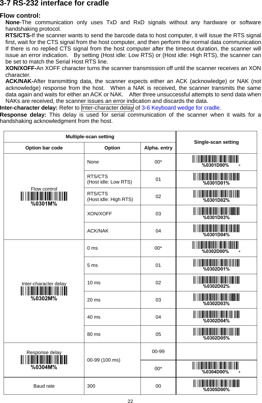
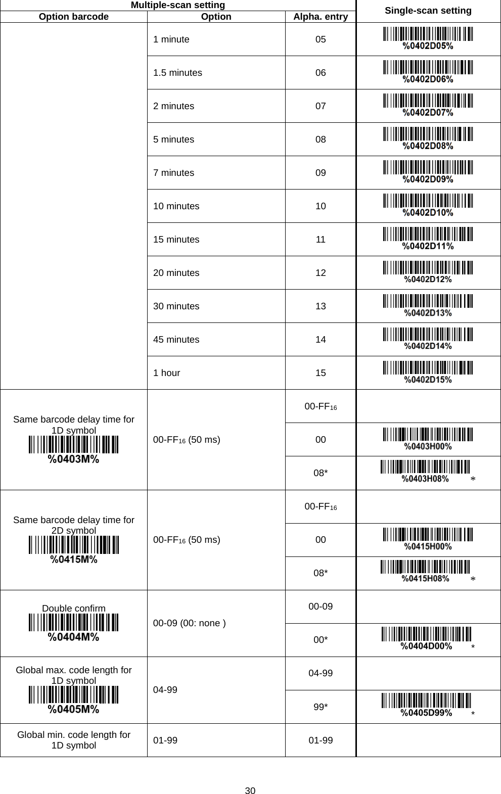
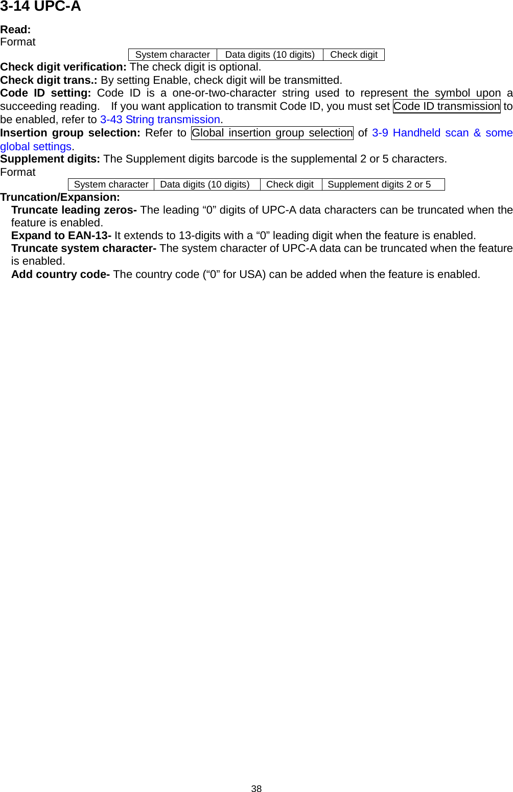
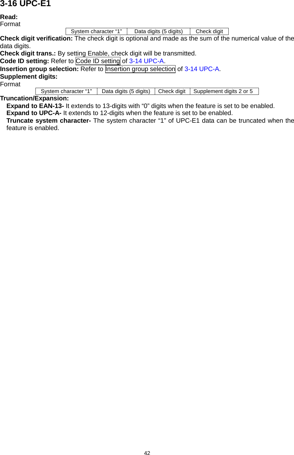
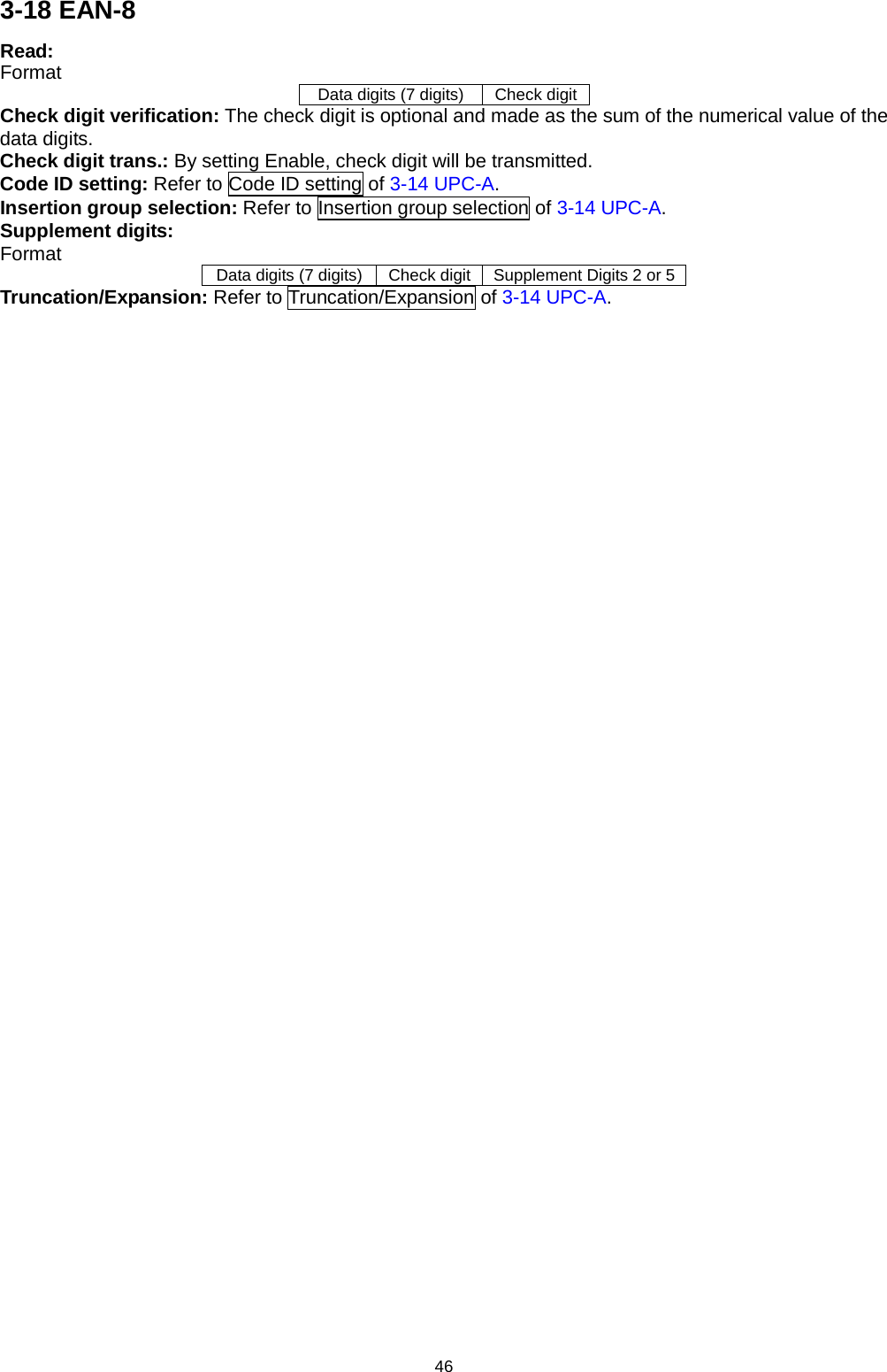
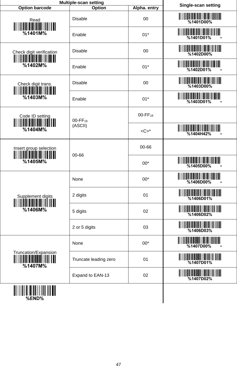
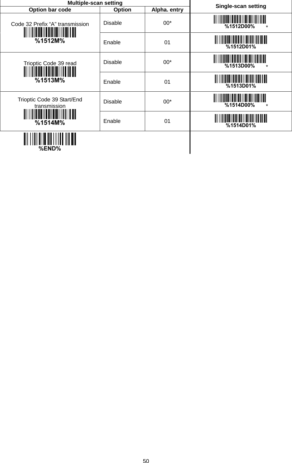
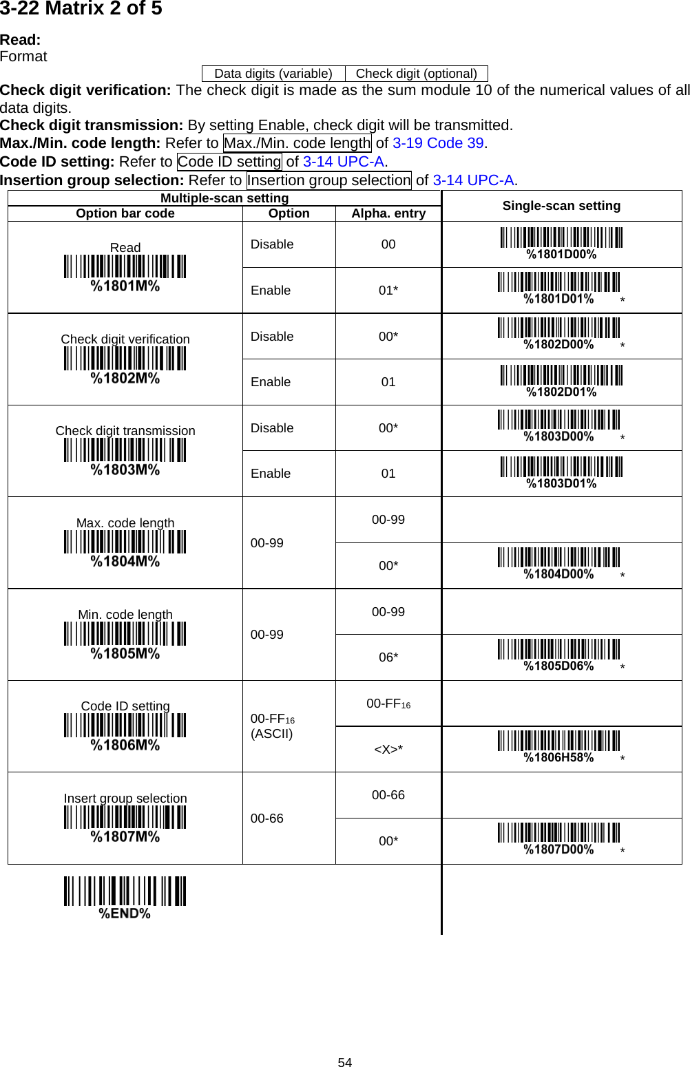
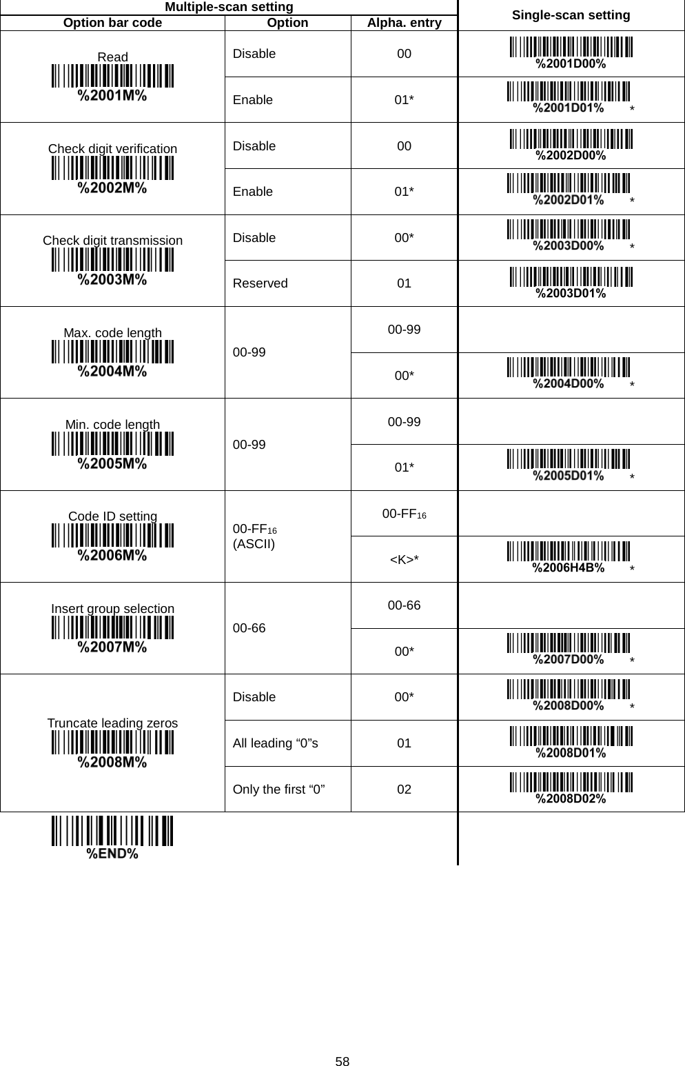
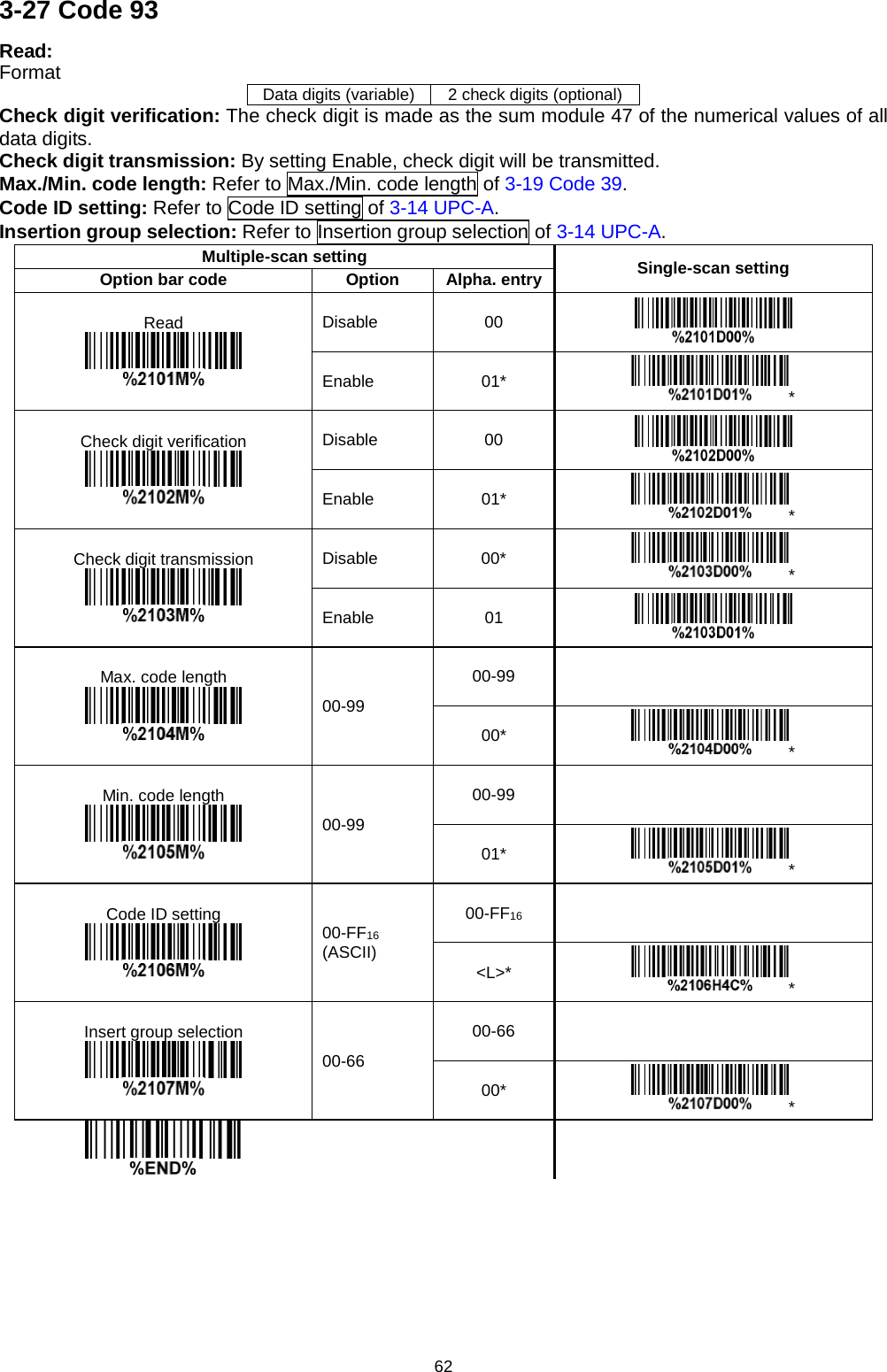
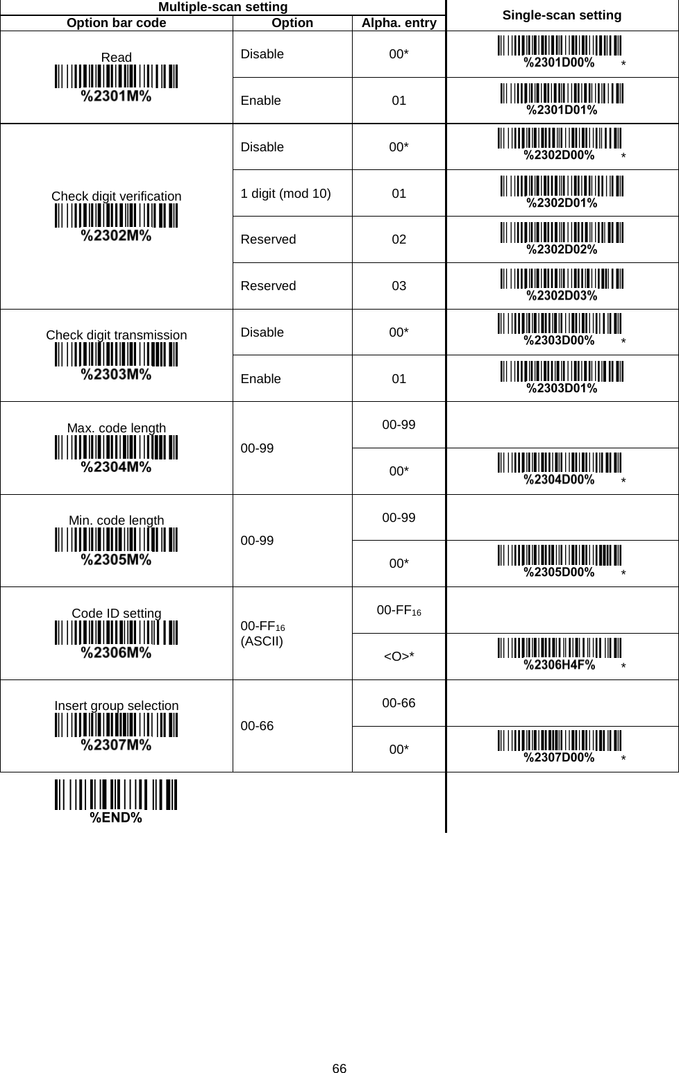
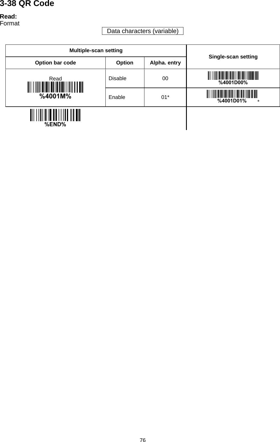
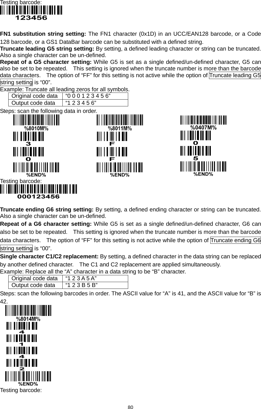
![3 1-2 Default setting for each barcode Code type Read enable Check digit verification Check digit transmission Min. code length Proprietary code ID AIM code ID UPC-A √ √ √ (12)2 A ]Em UPC-E √ √ √ (8)2 D ]Em UPC-E1 √ √ √ (8)2 D ]Em EAN-13 √ √ √ (13)2 A ]Em EAN-8 √ √ √ (8)2 C ]Em ISBN (Bookland EAN) / ISSN1 √ √ √ (13)2 B ]Em Code 39 √ - - 1 M ]Am Interleaved 2 of 5 √ - - 6 I ]Im Industrial 2 of 5 - - - 4 H ]Im Matrix 2 of 5 √ - - 6 X ]Im Codabar √ - - 4 N ]Fm Code 128 √ √ - 1 K ]Cm ISBT 128 √ √ - 1 K ]Cm Code 93 √ √ - 1 L ]Gm Code 11 - √ - 4 V - MSI/Plessey - - - 4 O ]Mm UK/Plessey - √ - 1 U ]Mm UCC/EAN 128 √ √ - 1 K ]Cm China Post √ - - (11)2 T ]Im China Finance √ - - (10)2 Y - GS1 DataBar √ - - (16)2 R ]em GS1 DataBar Truncated3 √ - - (16)2 R ]em GS1 DataBar Limited √ - - (16)2 R ]em GS1 DataBar Expanded √ - - 1 R ]em PDF417 √ - - - - - MicroPDF417 √ - - - - - DataMatrix √ - - - - - QR code √ - - - - - Aztec Code √ - - - - - Note: 1The settings for ISBN/ISSN and EAN-13 must be the same except the code ID. 2 Fixed-length barcodes. 3The settings for GS1 DataBar Truncated and GS1 DataBar must be the same.](https://usermanual.wiki/Minde-Electronics-Technology/CS2X90/User-Guide-3867133-Page-13.png)
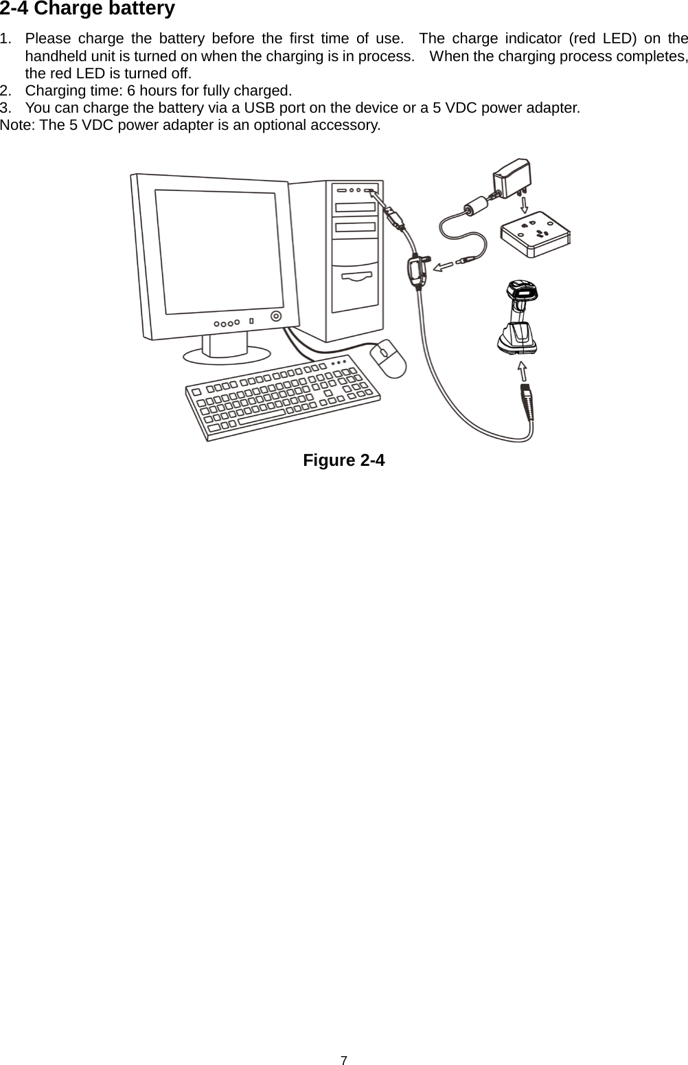
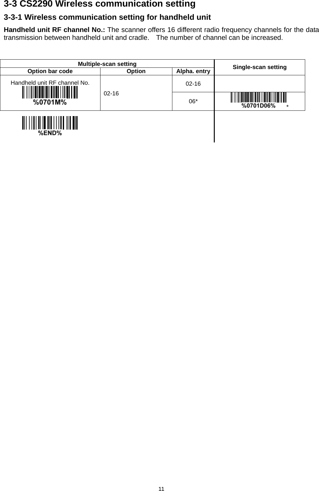
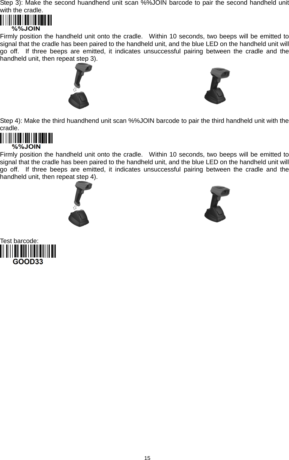
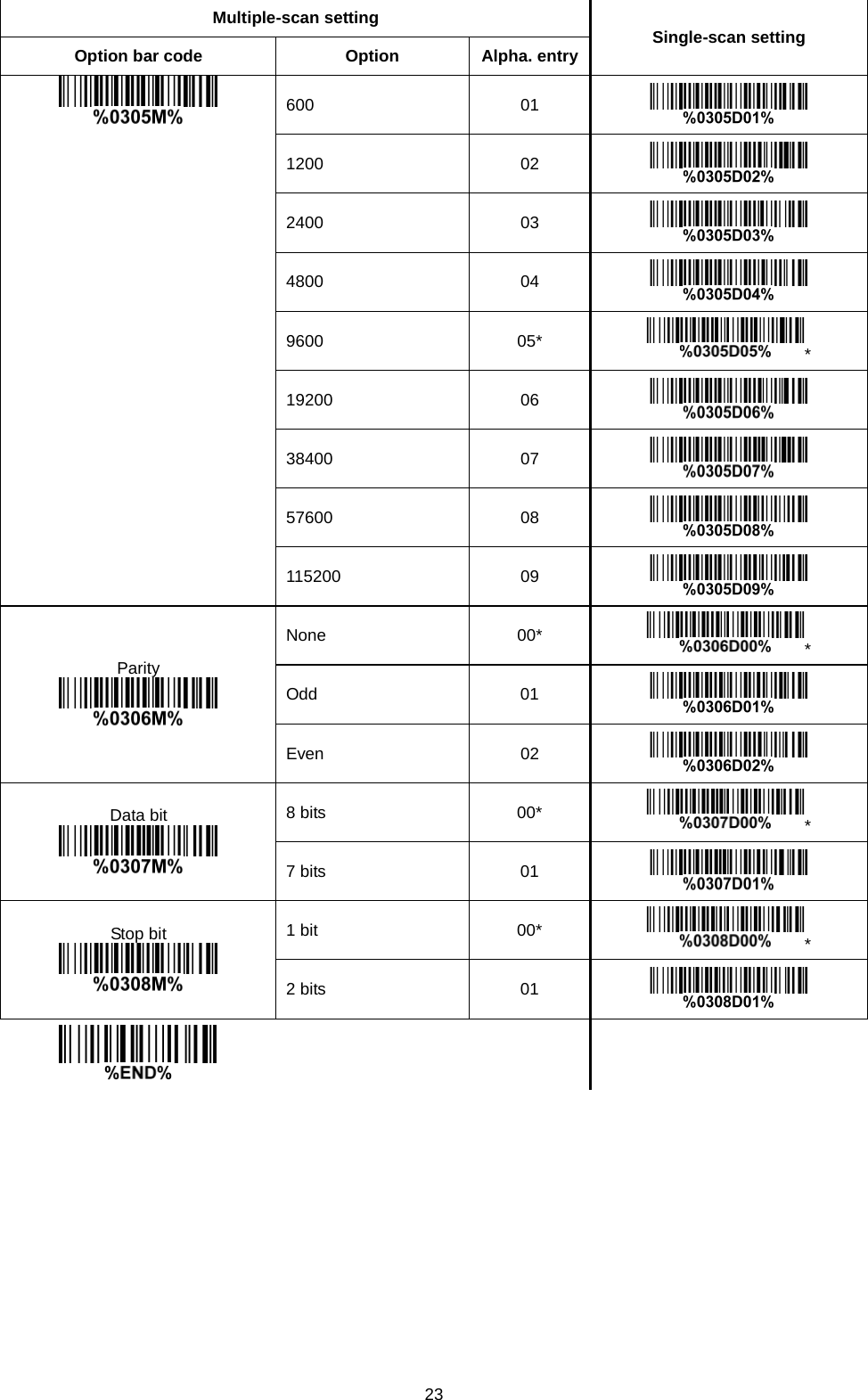
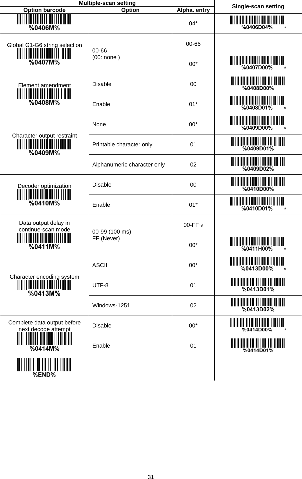
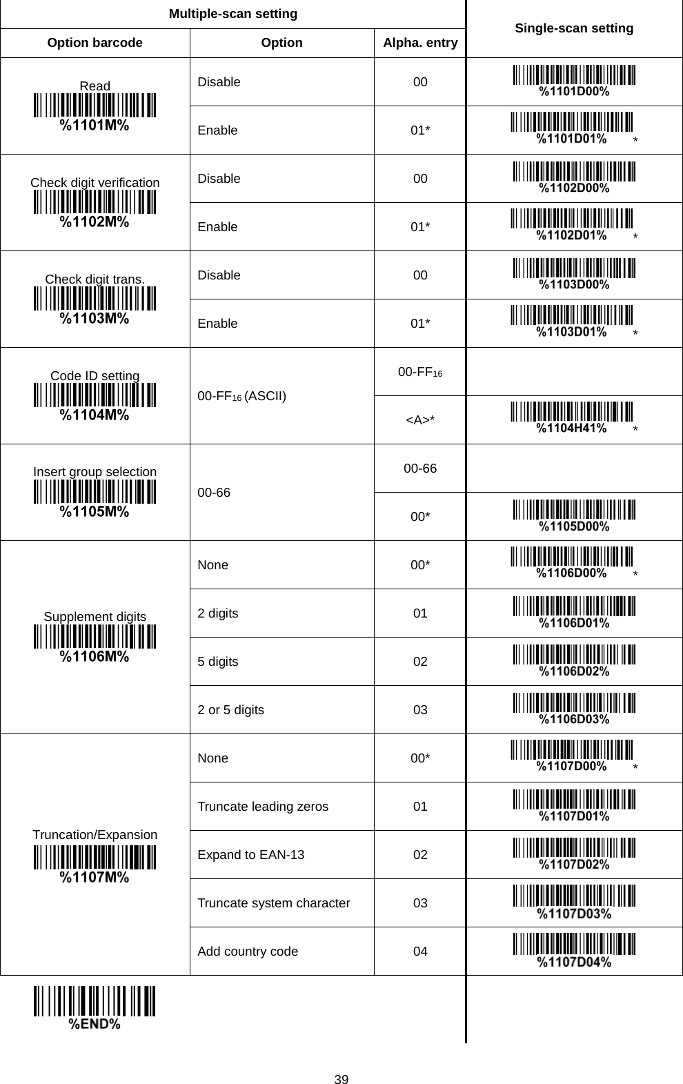
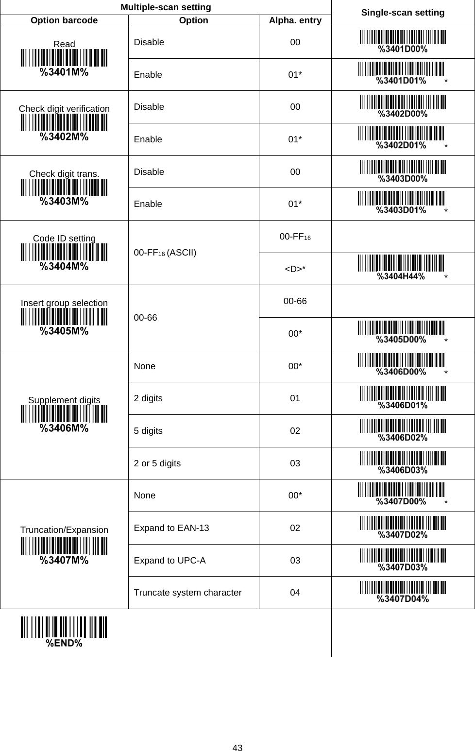
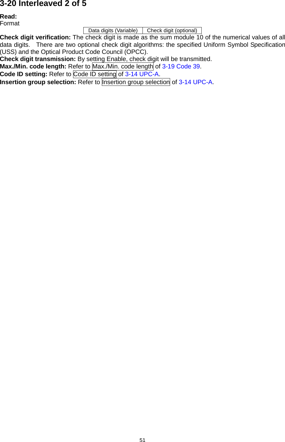
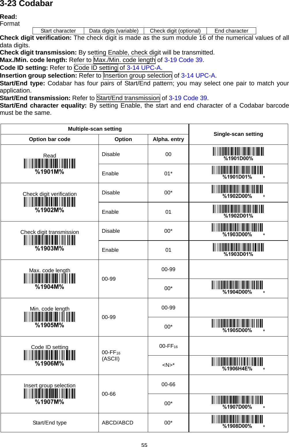
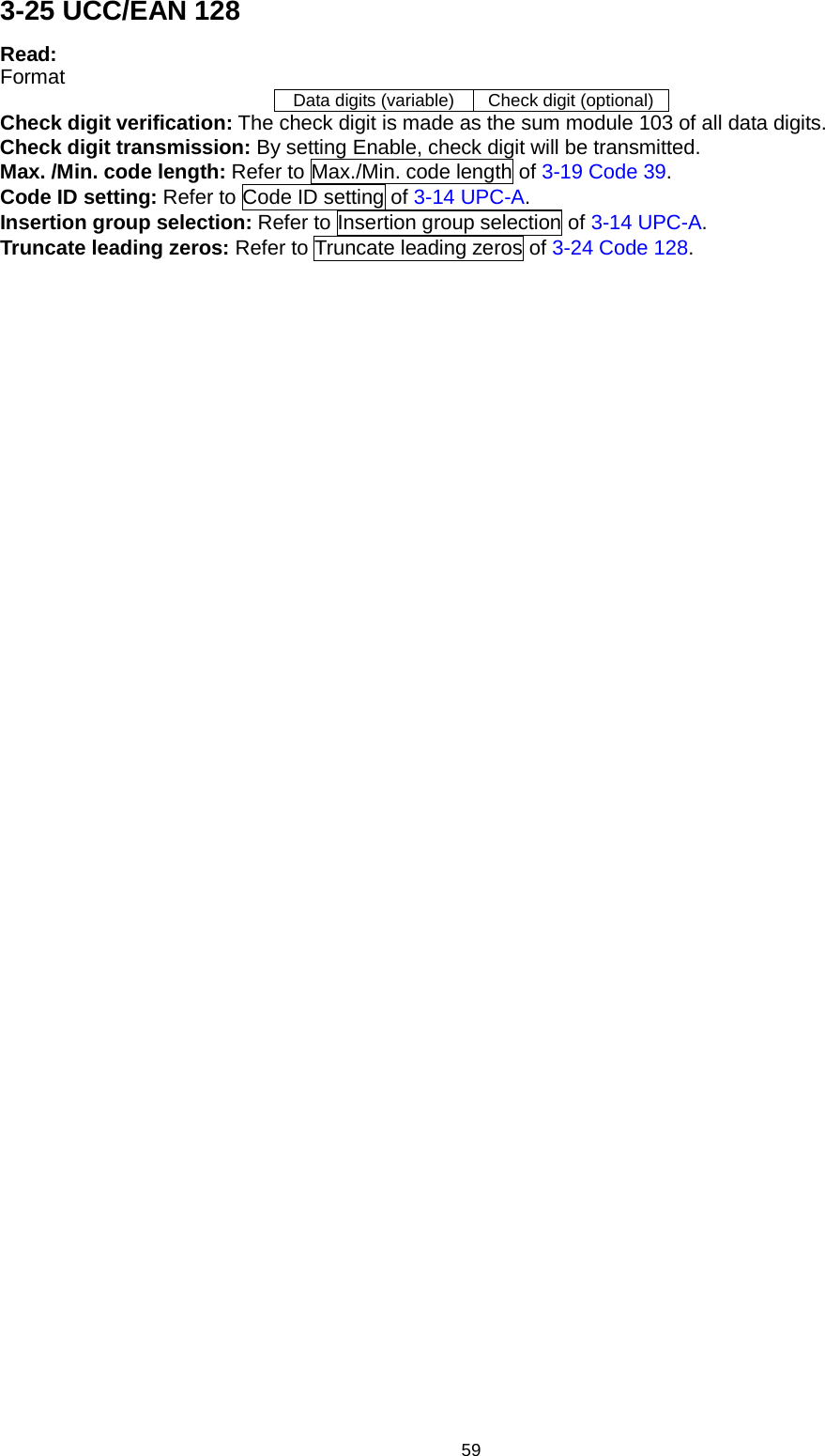
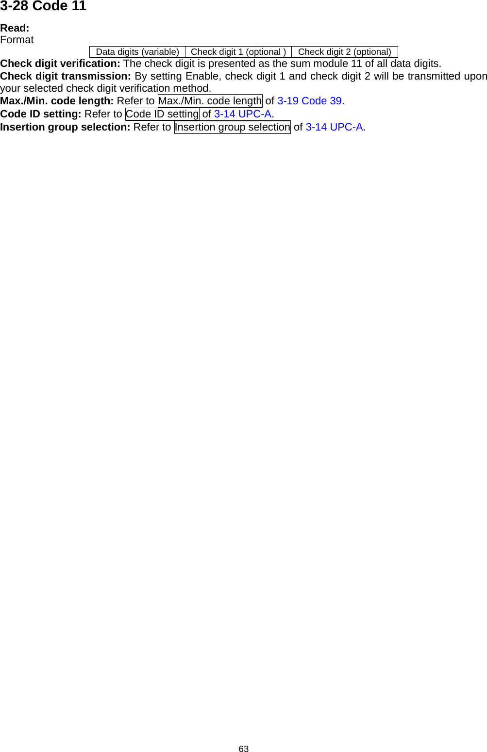
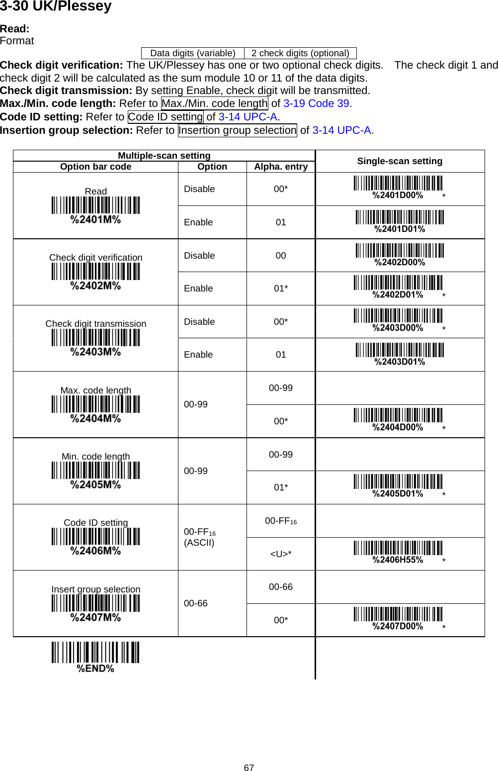
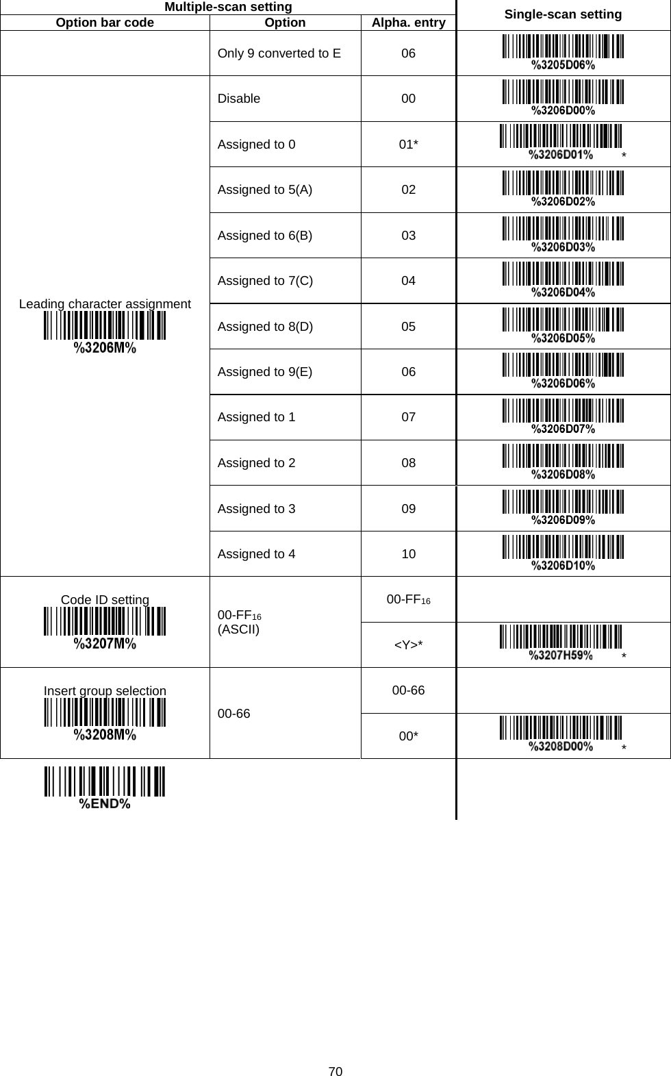
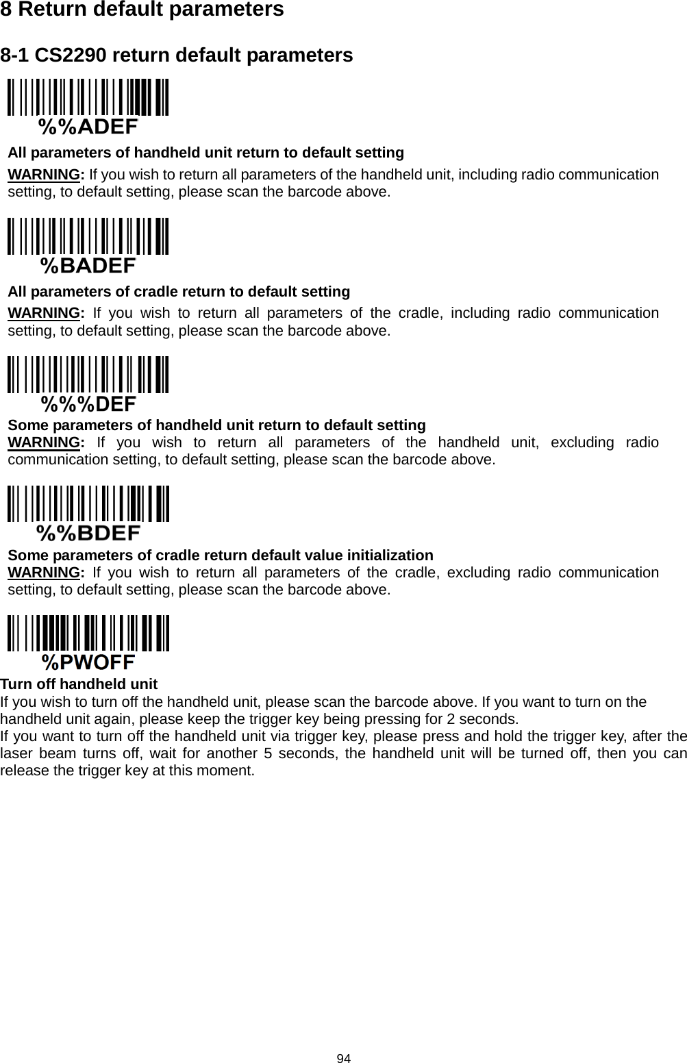
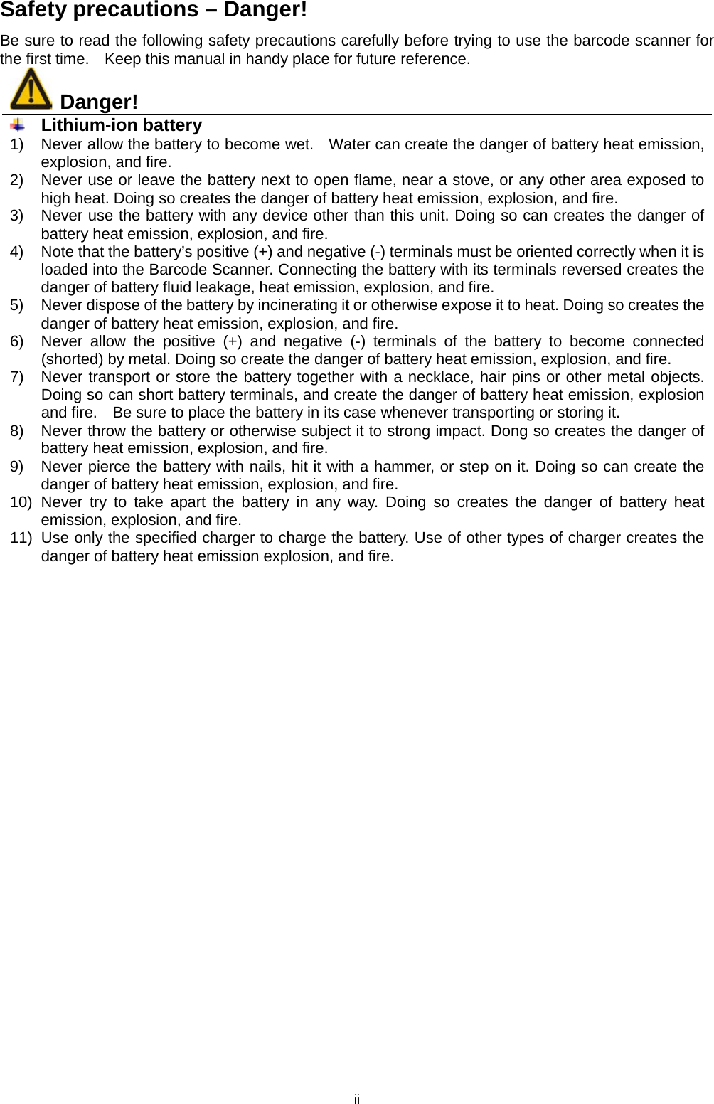
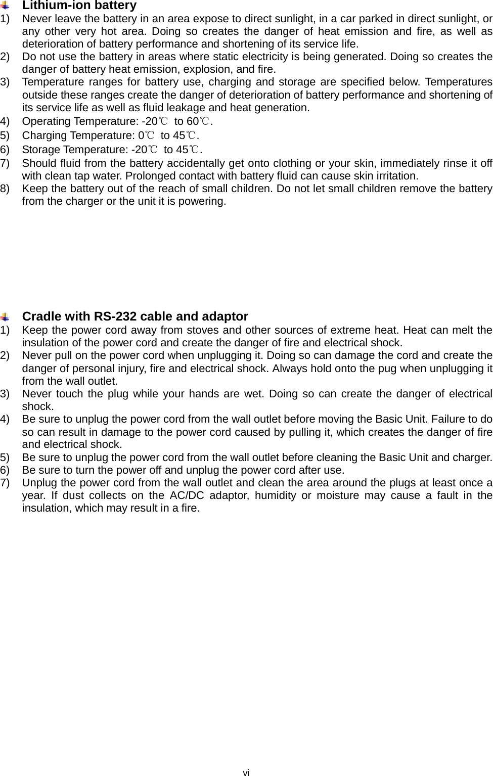
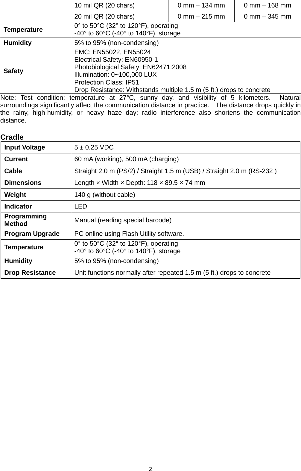
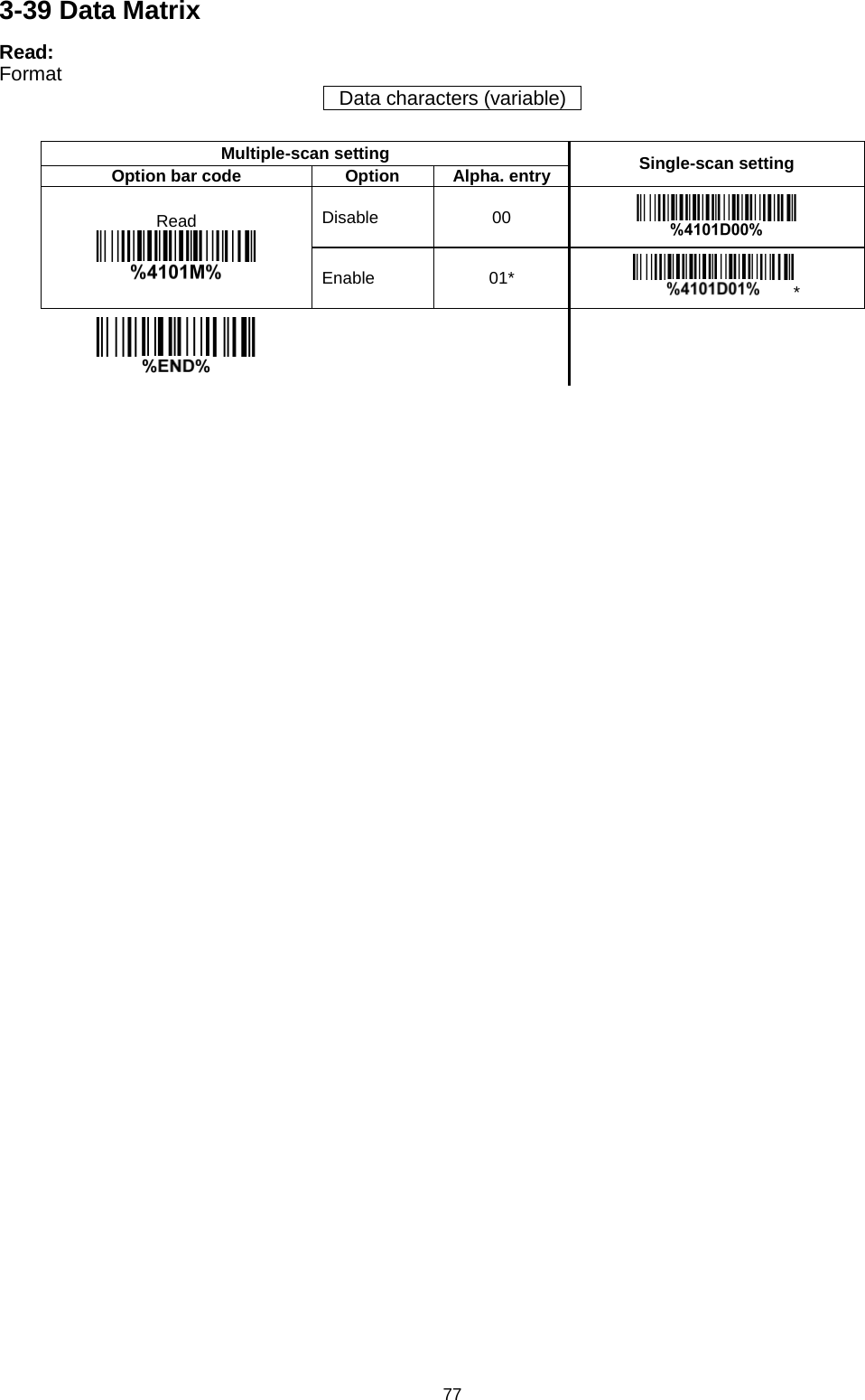
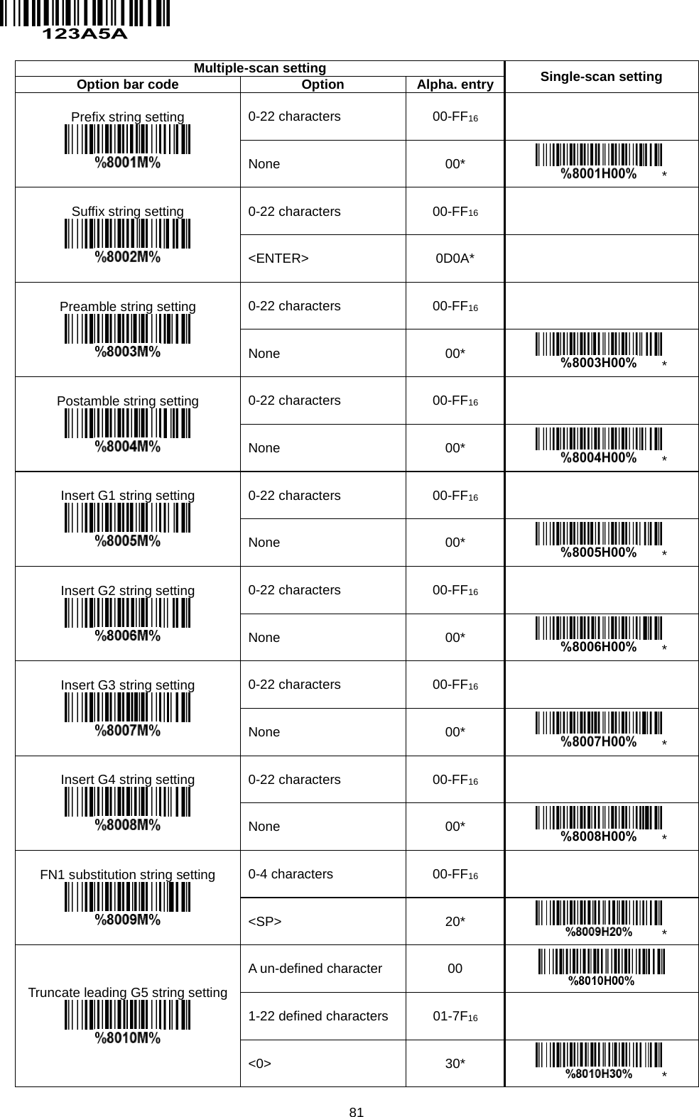
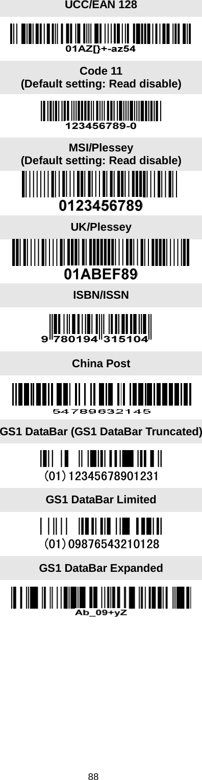
![71 3-33 GS1 DataBar (GS1 DataBar Truncated) GS1 DataBar Truncated is structured and encoded the same as the standard GS1 DataBar format, except its height is reduced to a 13 modules minimum; while GS1 DataBar should have a height greater than or equal to 33 modules. Read: Format 16 Data digits Code ID setting: Refer to Code ID setting of 3-14 UPC-A. Insertion group selection: Refer to Insertion group selection of 3-14 UPC-A. Conversion: UCC/EAN 128- Refer to Code ID transmission of 3-43 String transmission, ]Cm will be identified as AIM ID. UPC-A or EAN-13- Barcode beginning with a single zero as the first digit has the leading “010” stripped and the barcode reported as EAN-13. Barcode beginning with two or more zeros but not six zeros has the leading “0100” stripped and the barcode reported as UPC-A. Multiple-scan setting Single-scan setting Option bar code Option Alpha. entry Read Disable 00 Enable 01* * Code ID setting 00-FF16 (ASCII) 00-FF16 <R>* * Insert group selection 00-66 00-66 00* * Conversion None 00* * UCC/EAN 128 01 UPC-A or EAN-13 02](https://usermanual.wiki/Minde-Electronics-Technology/CS2X90/User-Guide-3867133-Page-81.png)
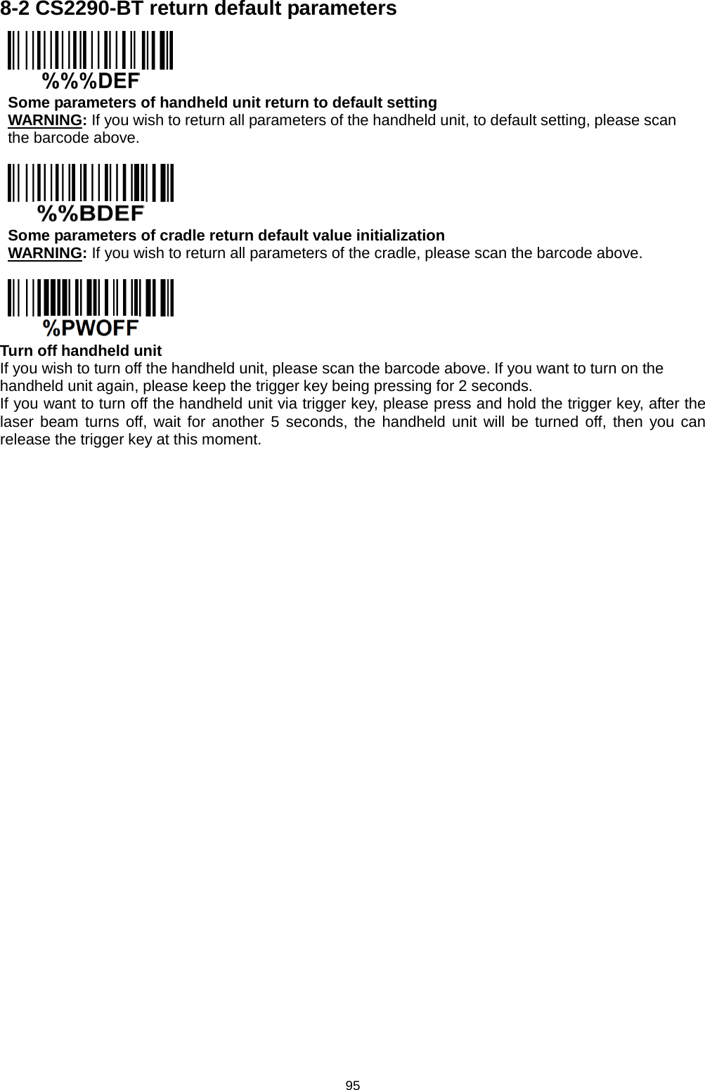
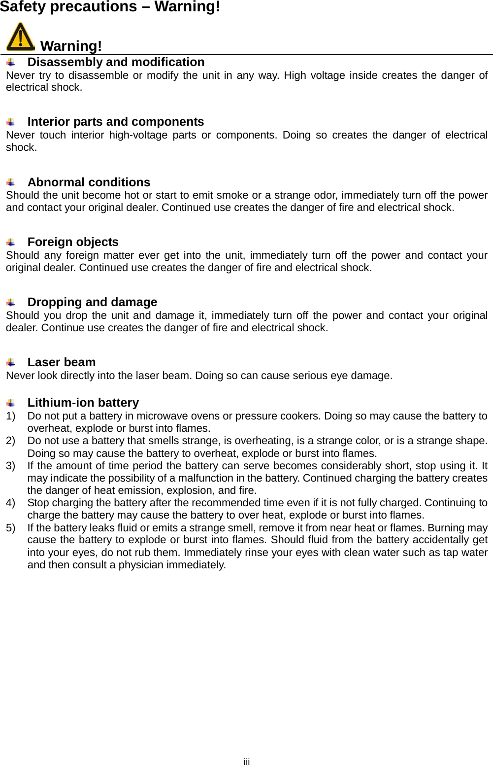
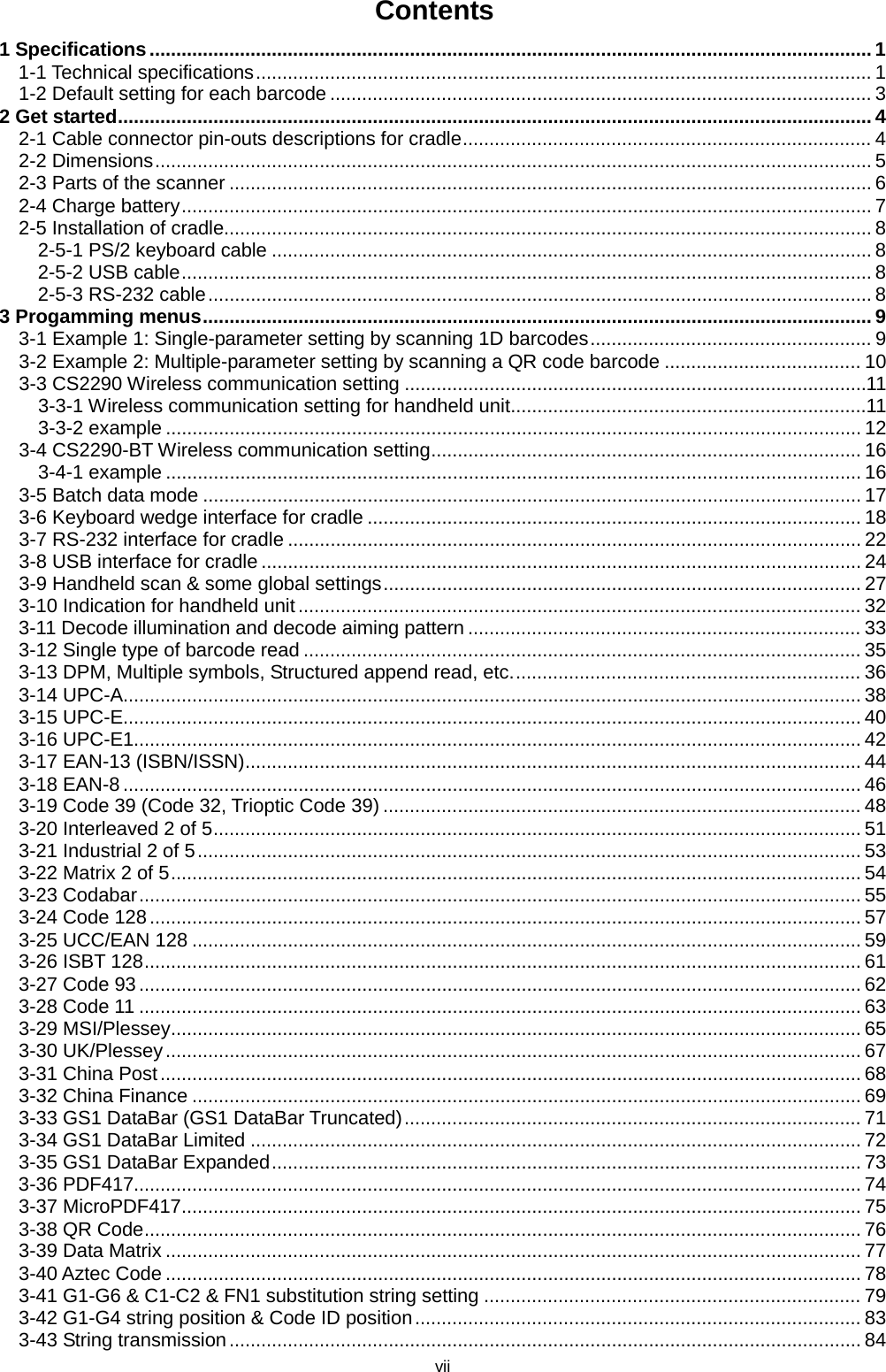
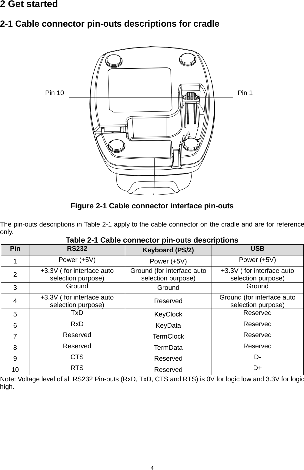
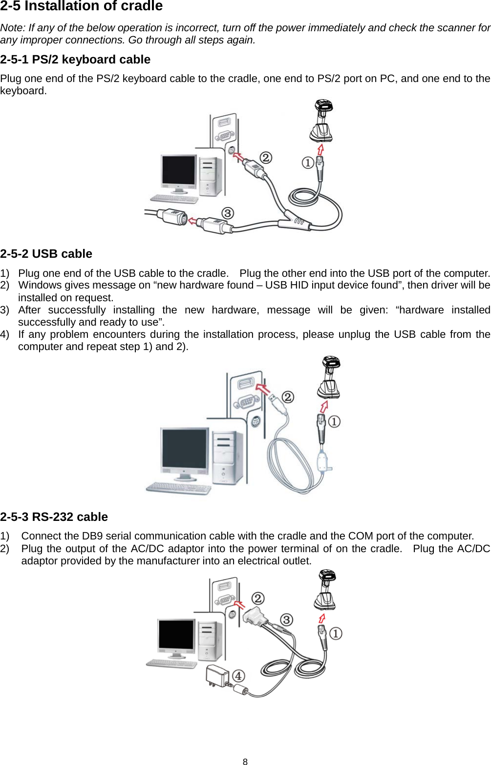
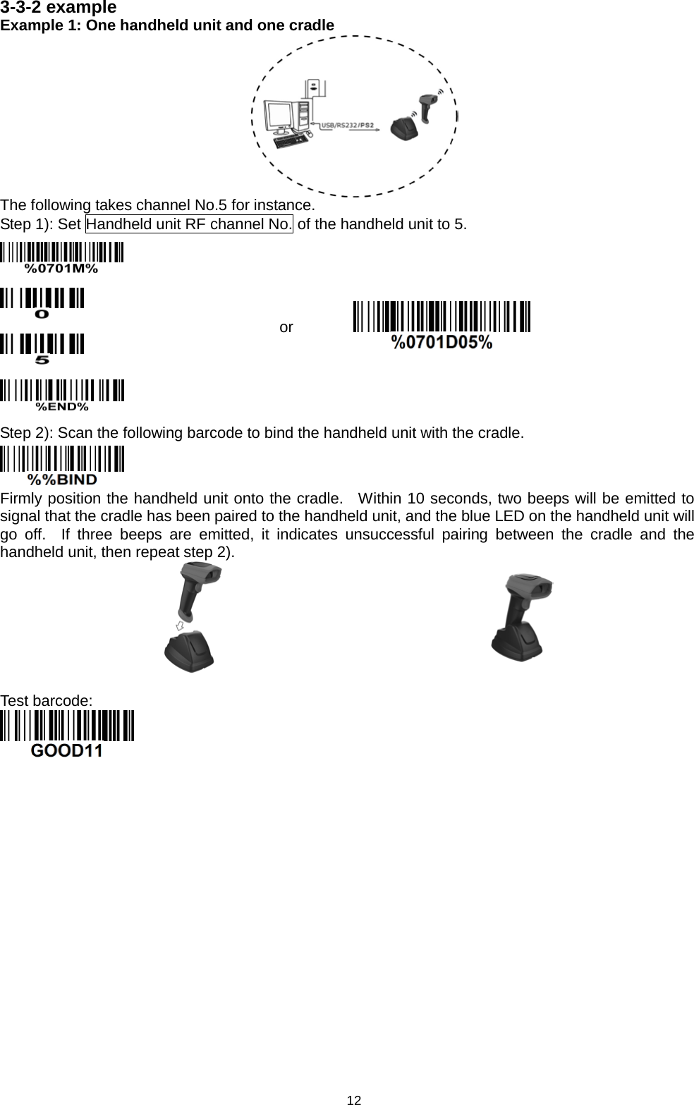
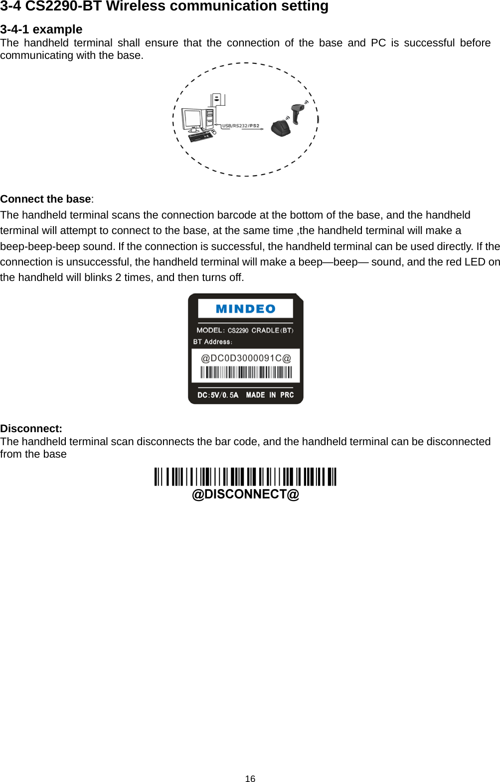
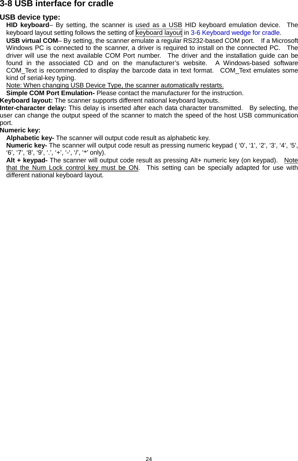
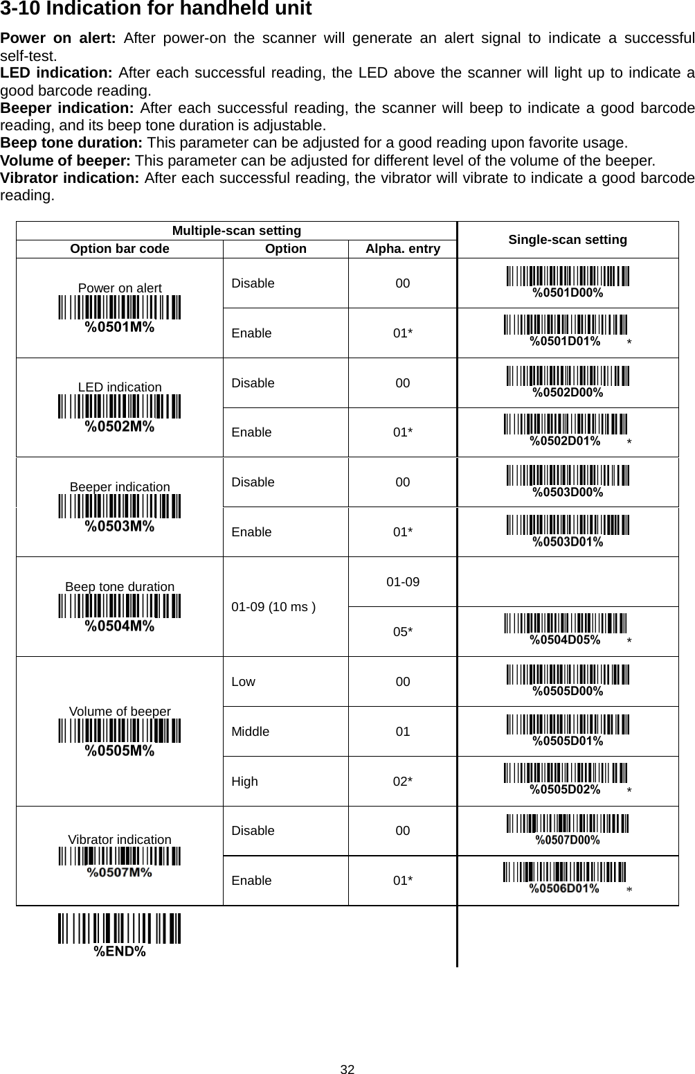
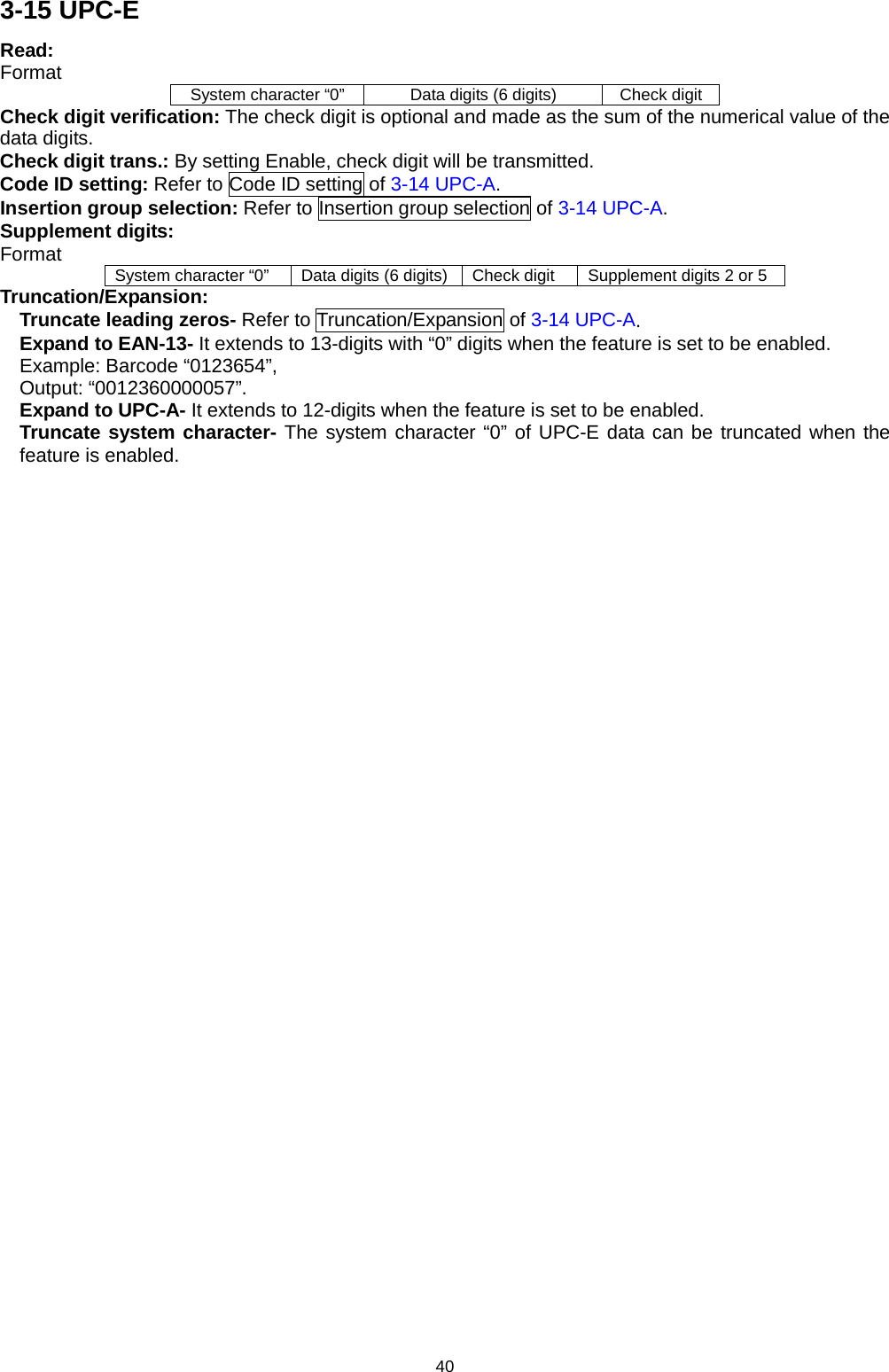
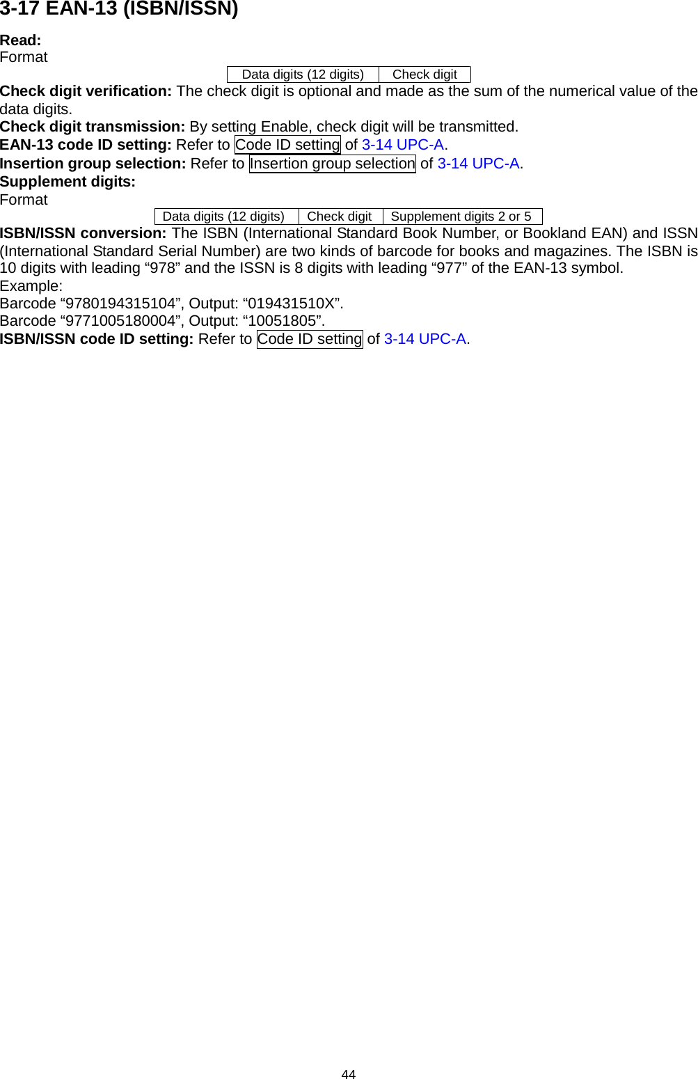
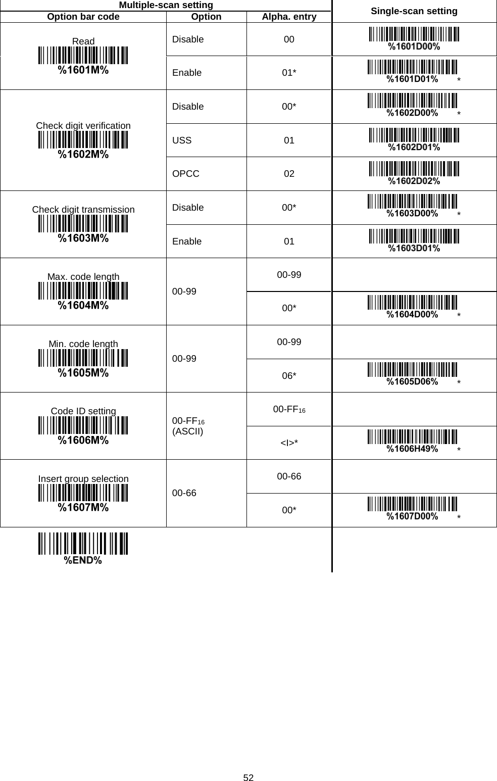
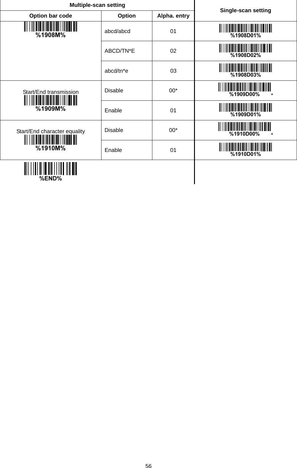
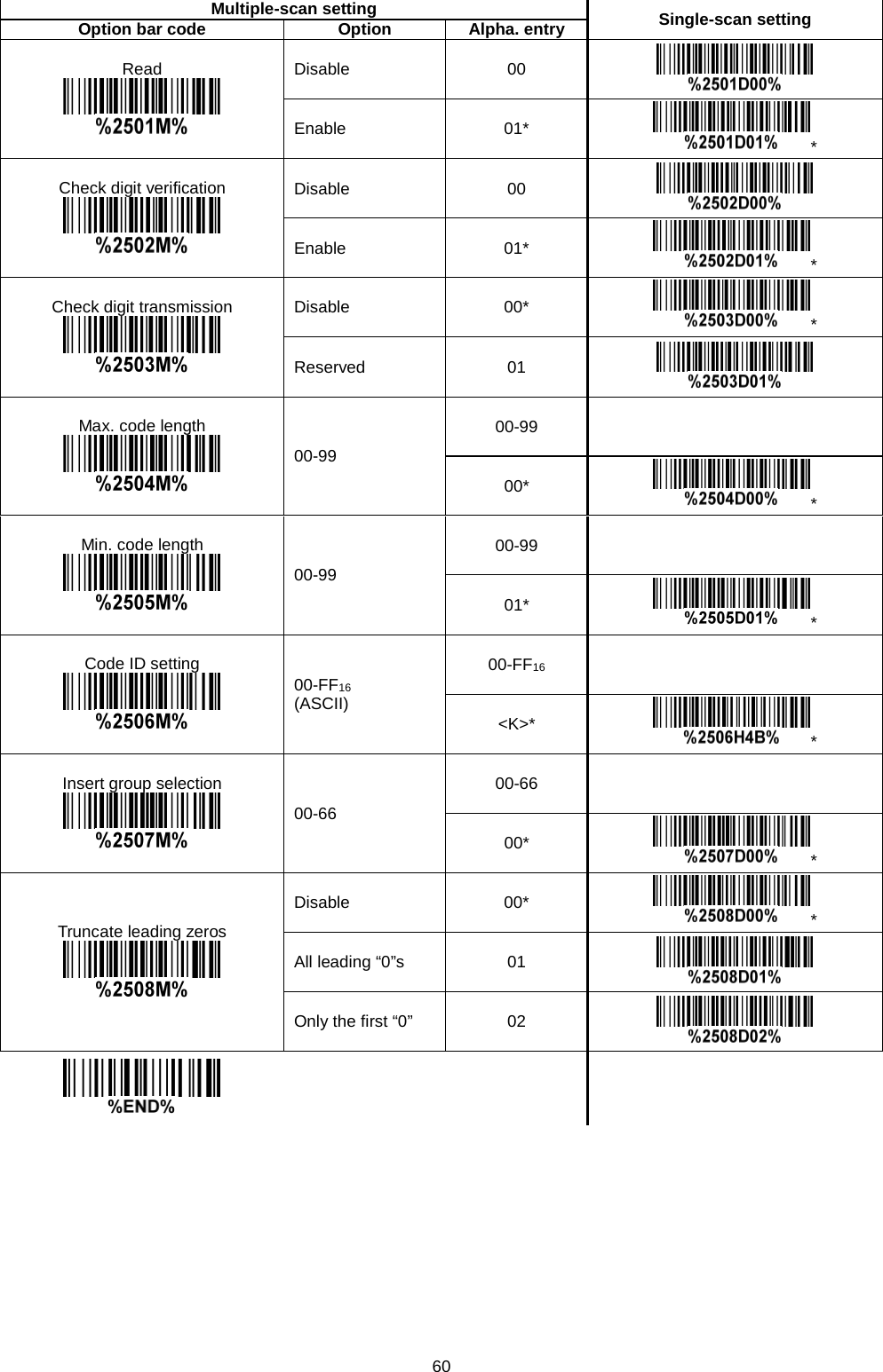
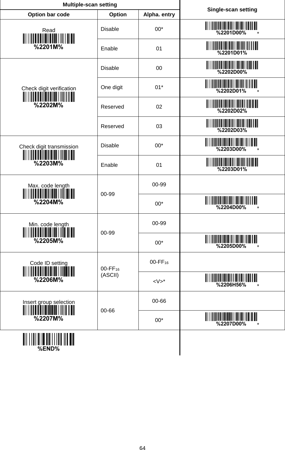
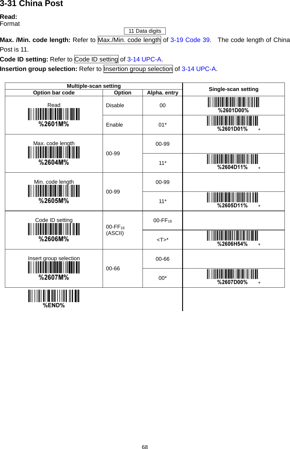
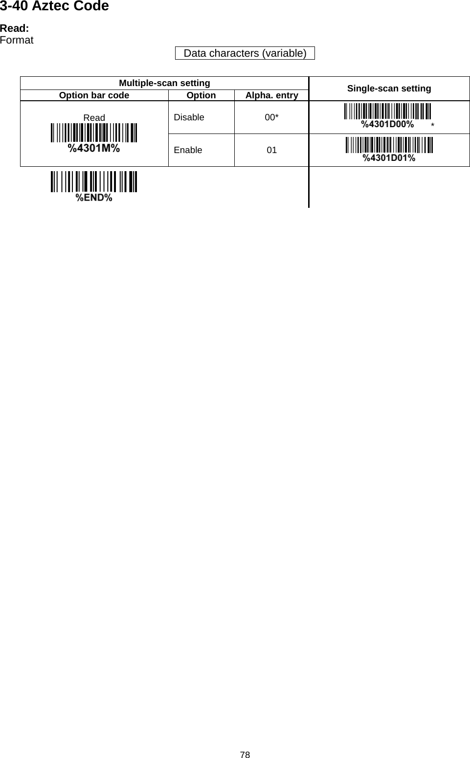
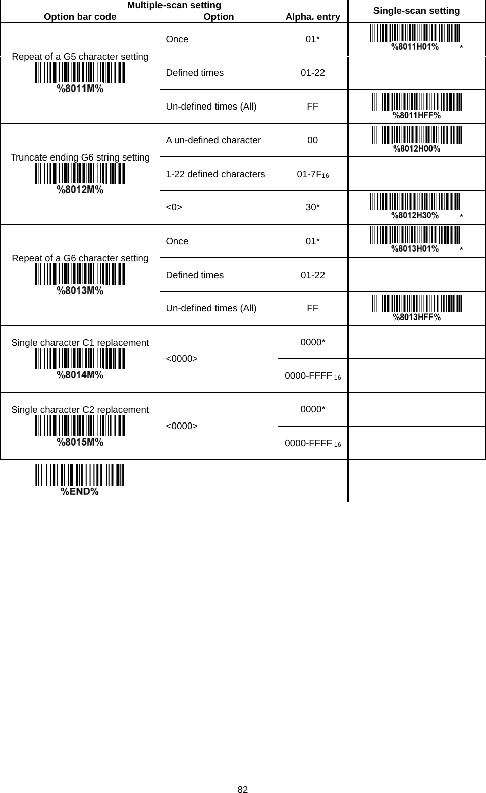
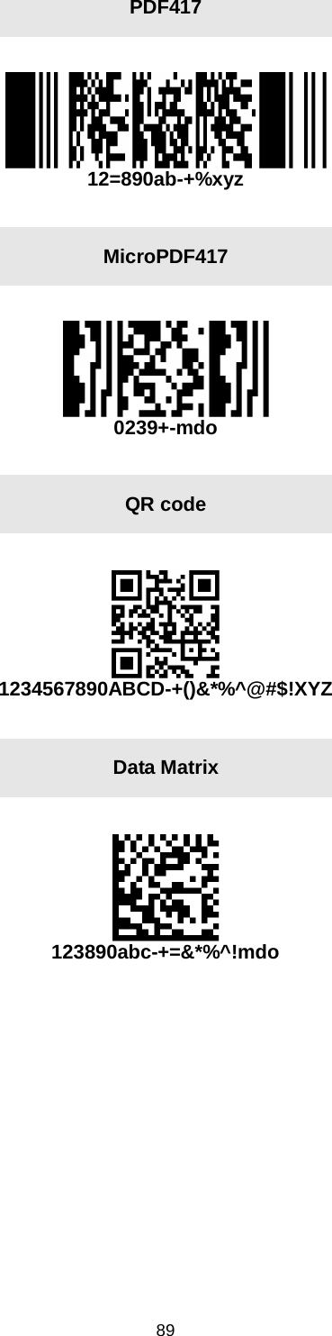
![73 3-35 GS1 DataBar Expanded Read: Format Data characters (variable) Code ID setting: Refer to Code ID setting of 3-14 UPC-A. Insertion group selection: Refer to Insertion group selection of 3-14 UPC-A. Conversion: UCC/EAN 128- Refer to Code ID transmission of 3-43 String transmission, ]Cm will be identified as AIM ID. Multiple-scan setting Single-scan setting Option bar code Option Alpha. entry Read Disable 00 Enable 01* * Max. code length 00-99 00-99 00* * Min. code length 00-99 00-99 01* * Code ID setting 00-FF16 (ASCII) 00-FF16 <R>* * Insert group selection 00-66 00-66 00* * Conversion None 00* * UCC/EAN 128 01](https://usermanual.wiki/Minde-Electronics-Technology/CS2X90/User-Guide-3867133-Page-83.png)
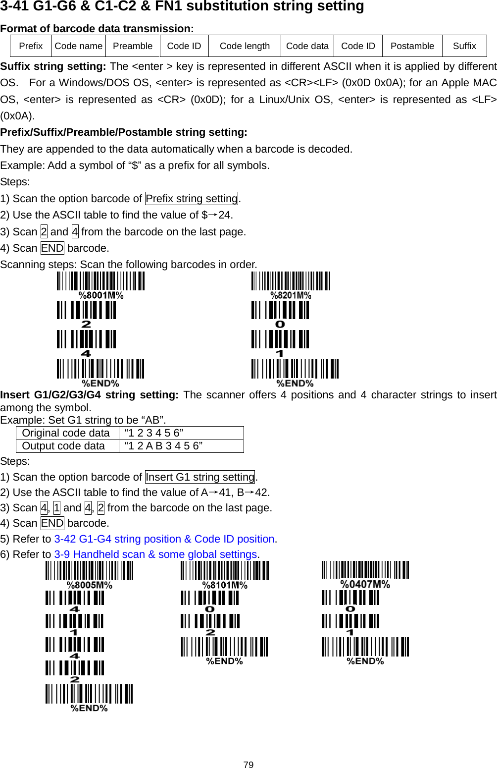
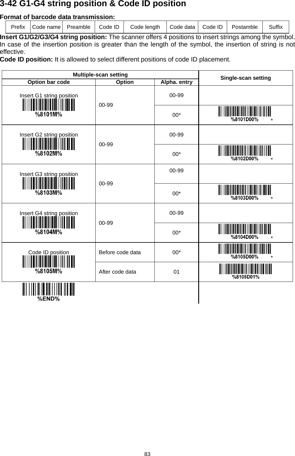
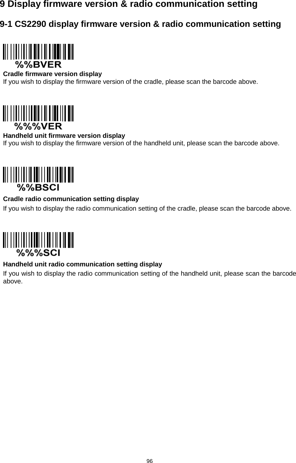
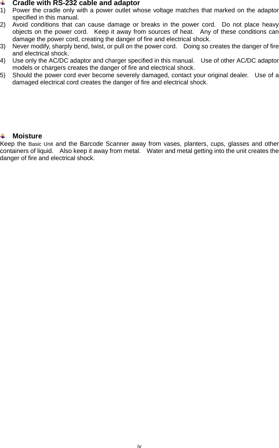
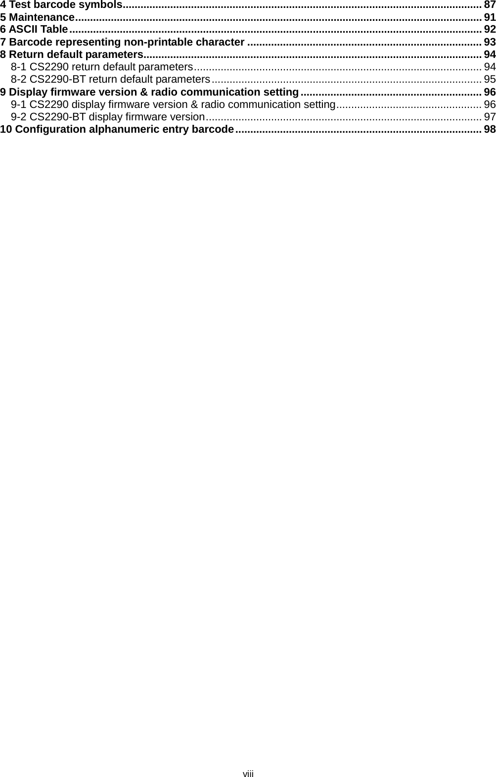
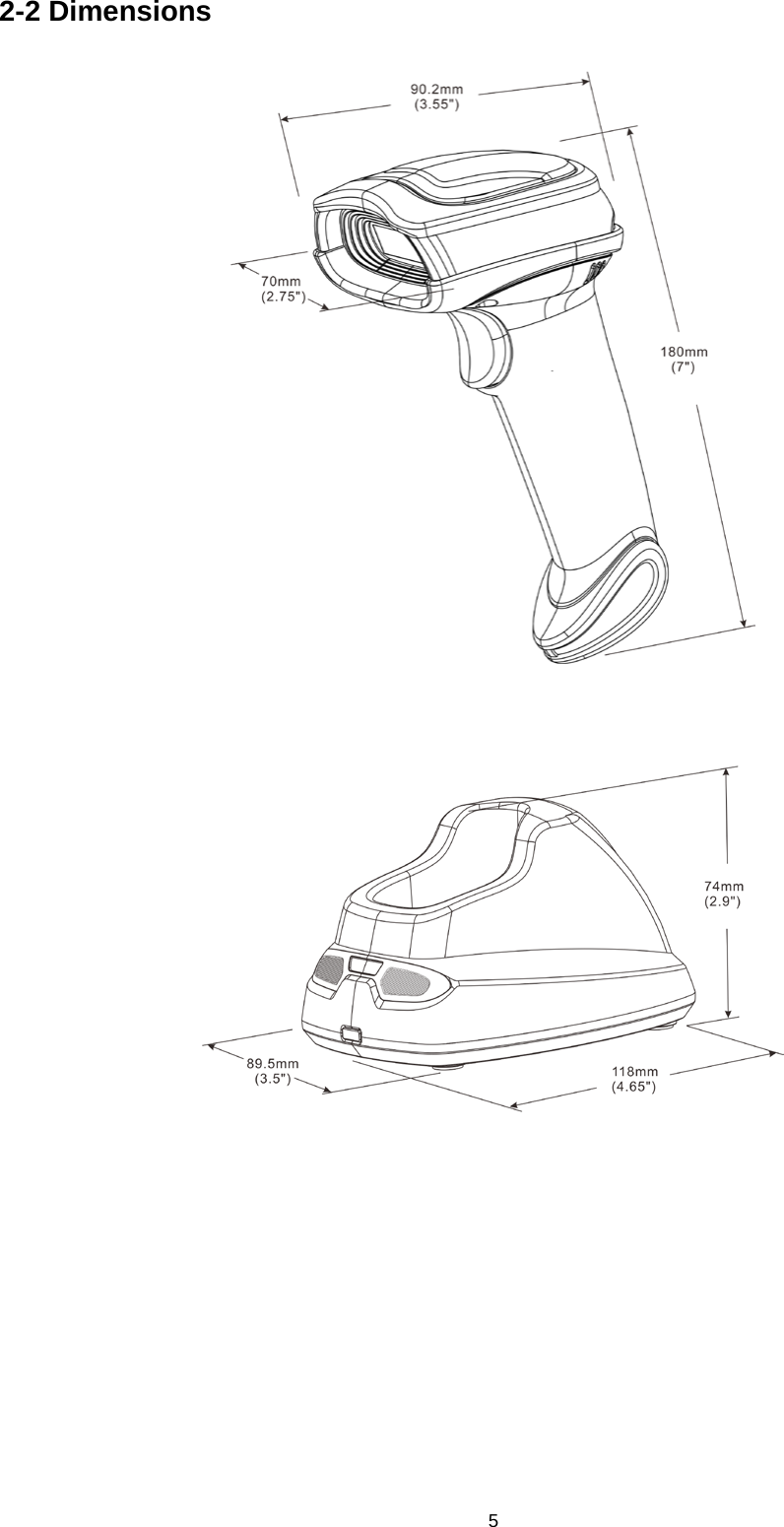
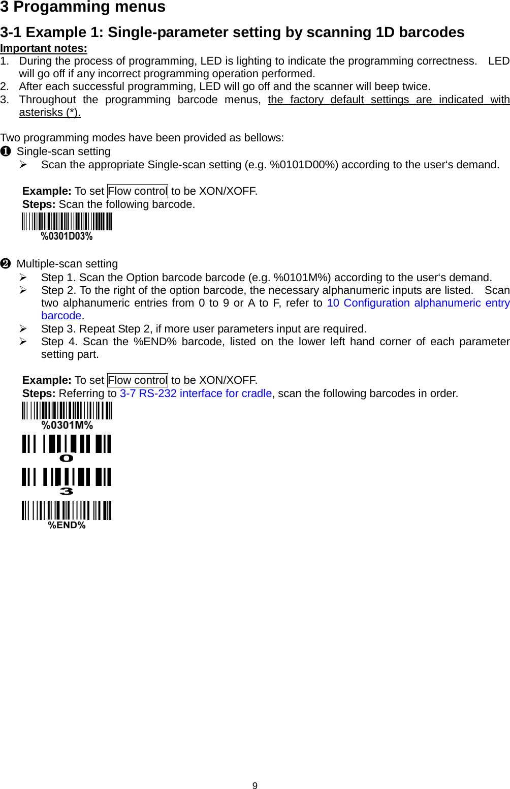
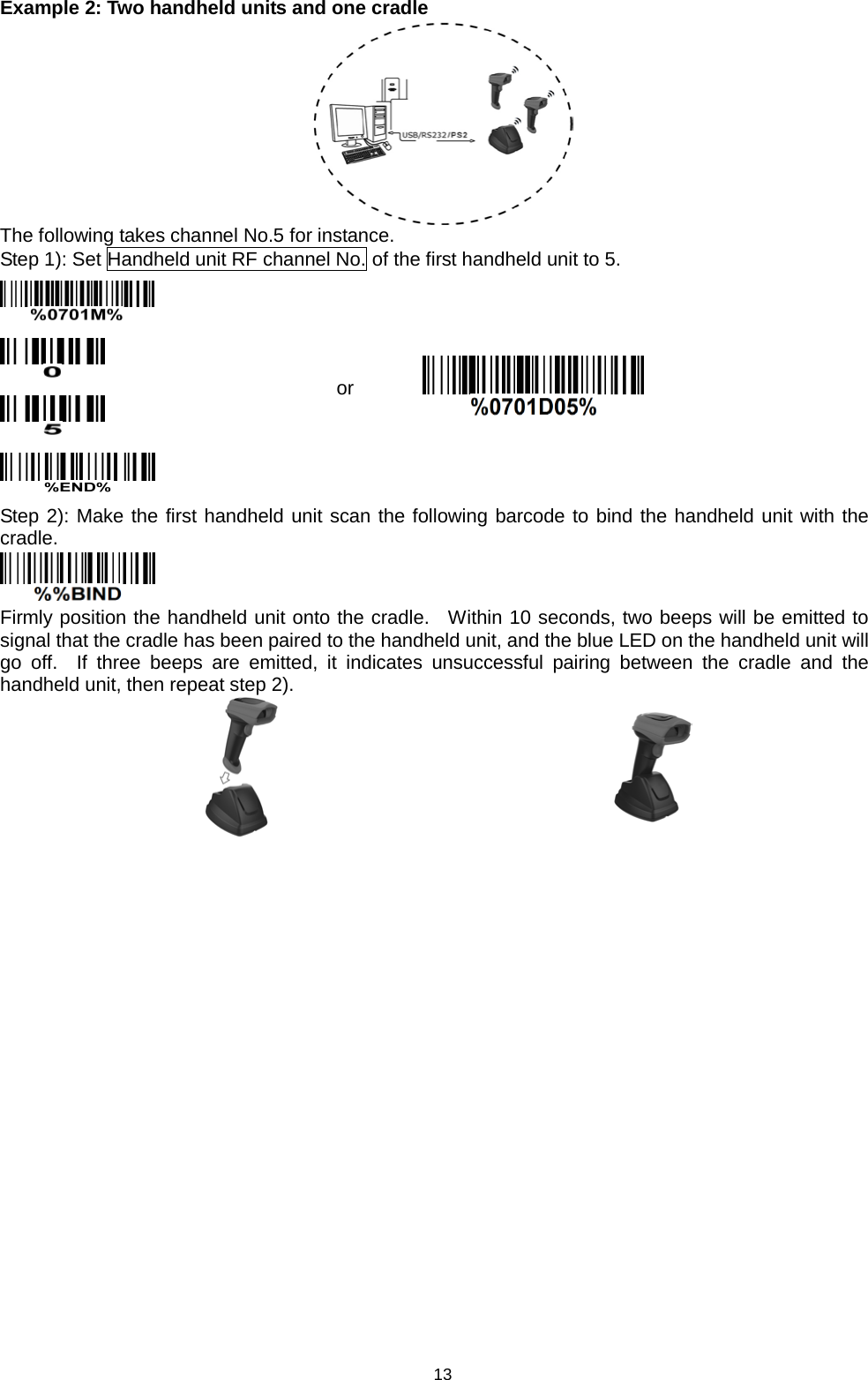
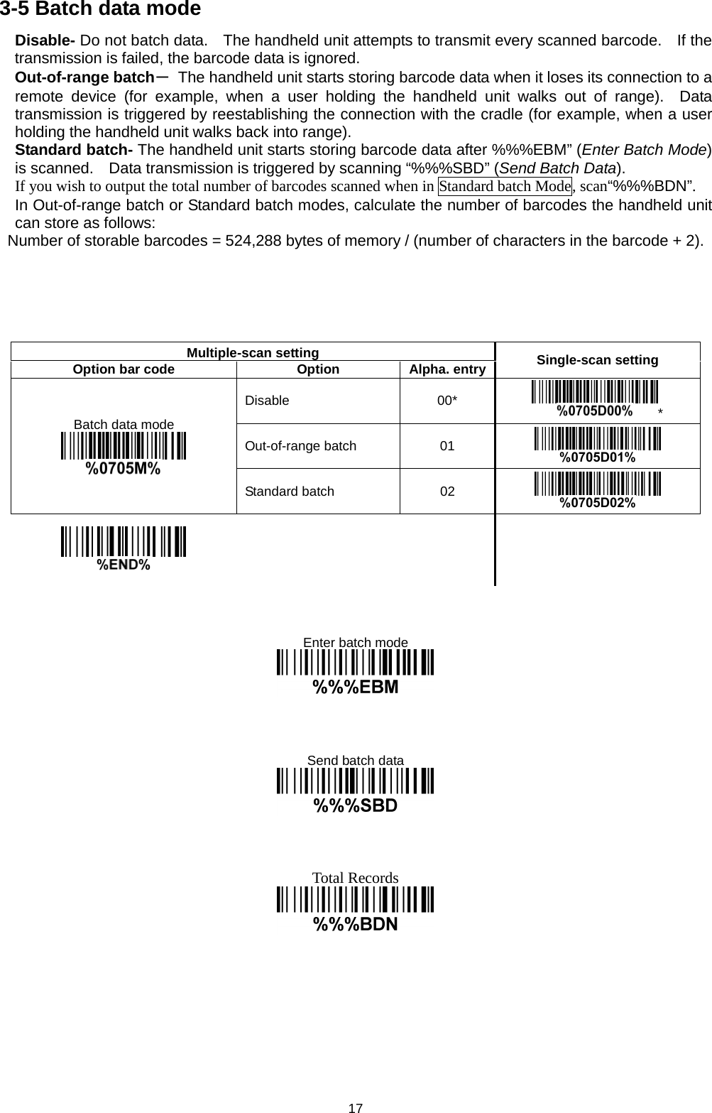
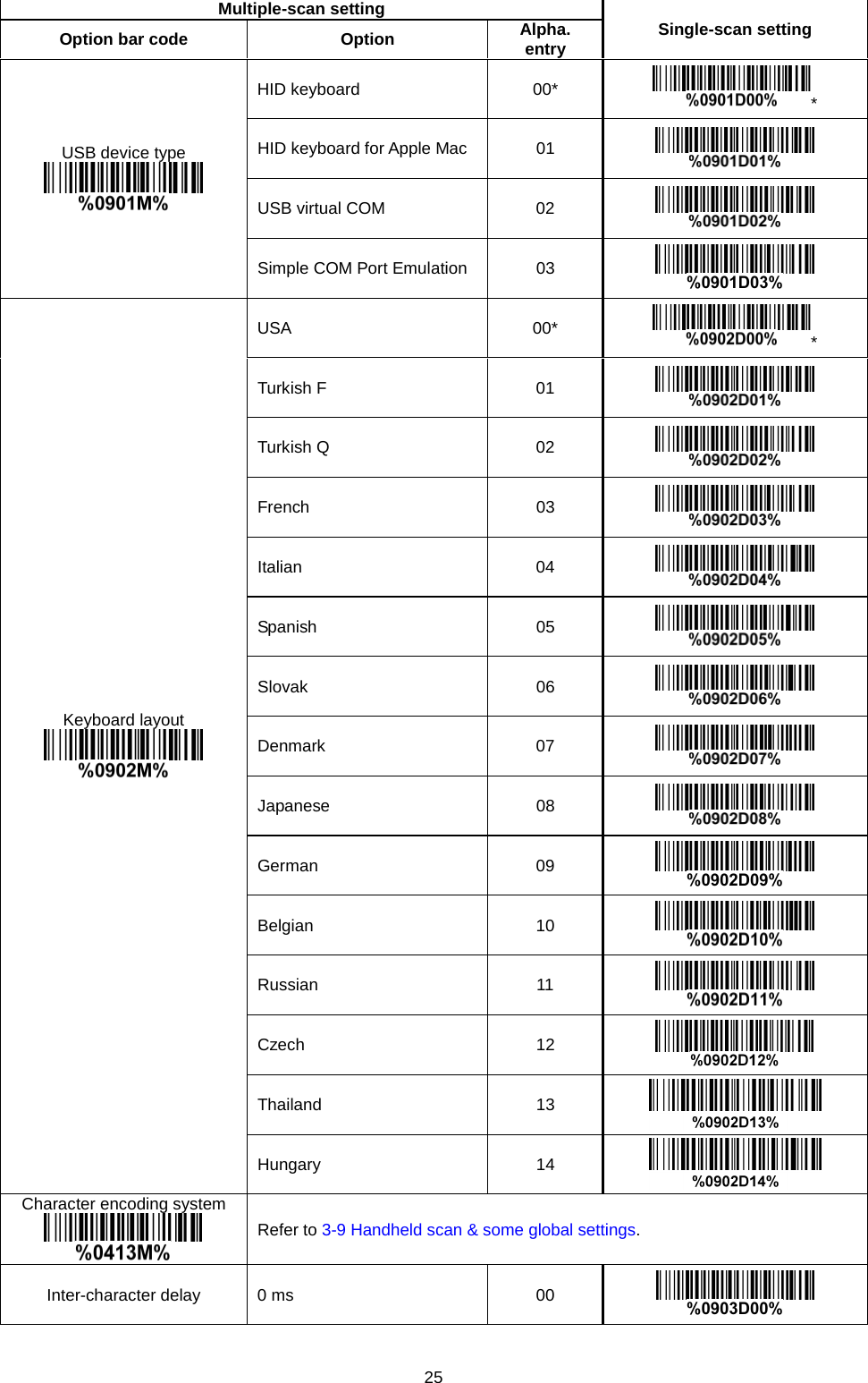
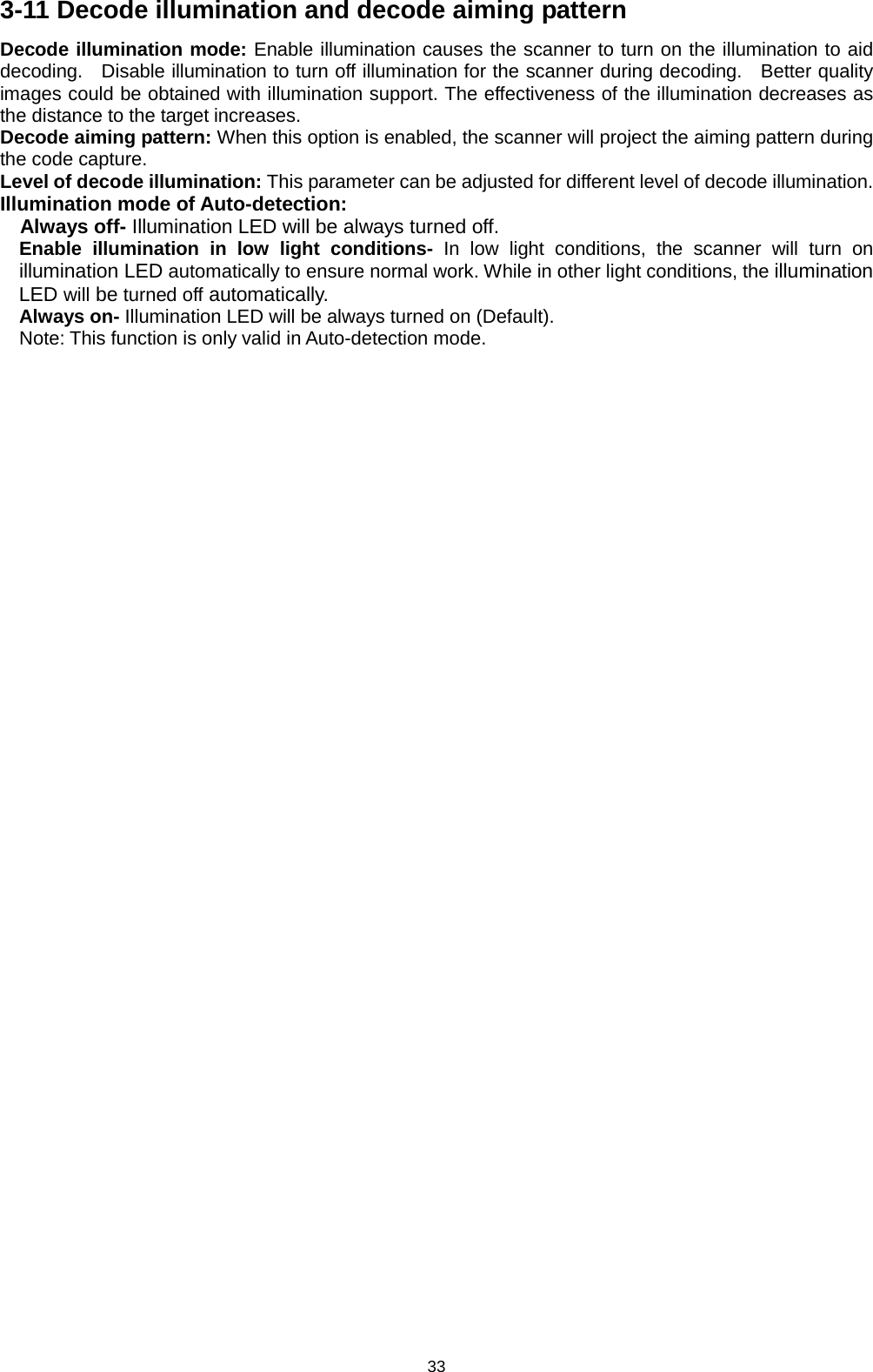
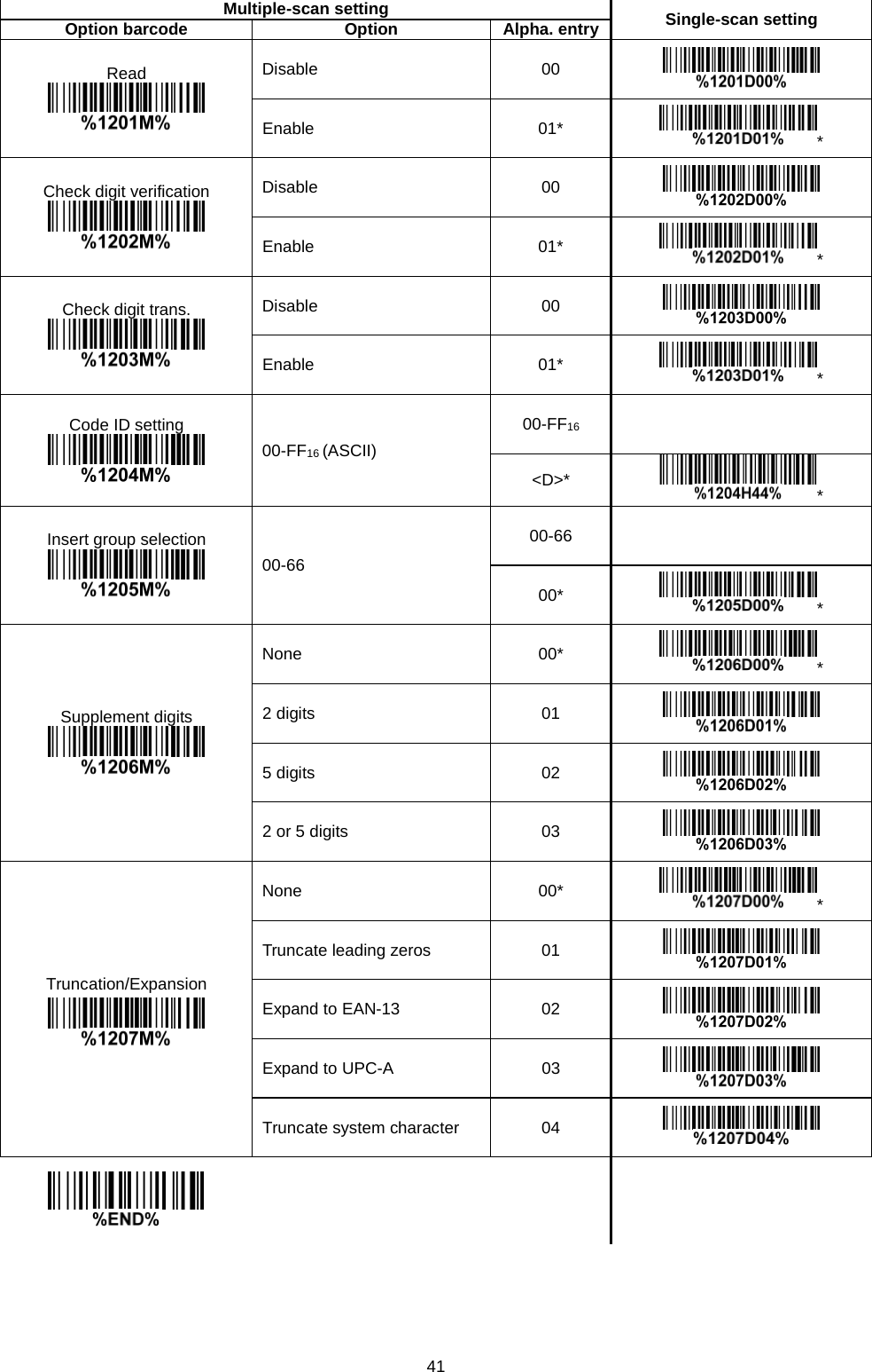
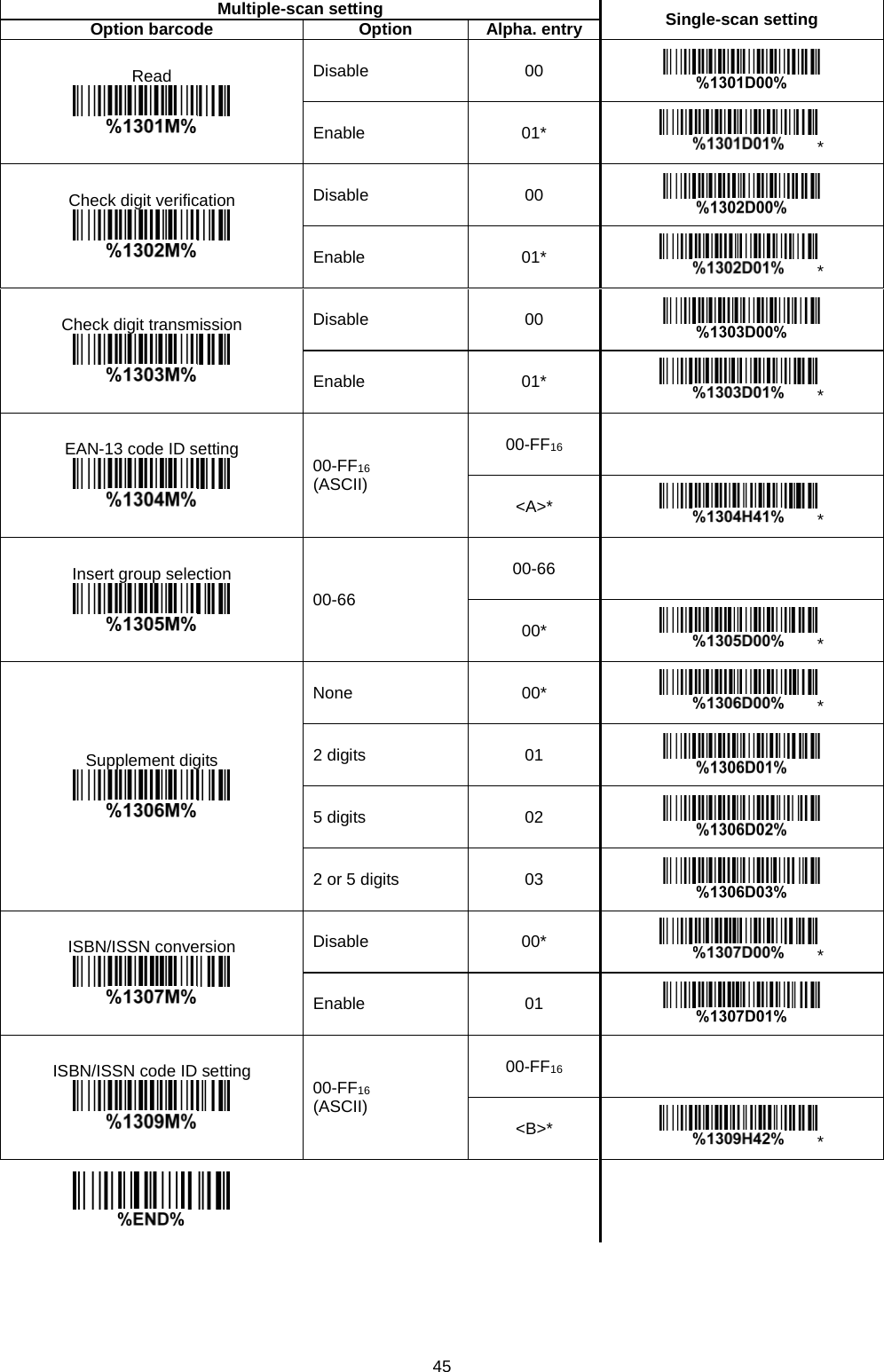
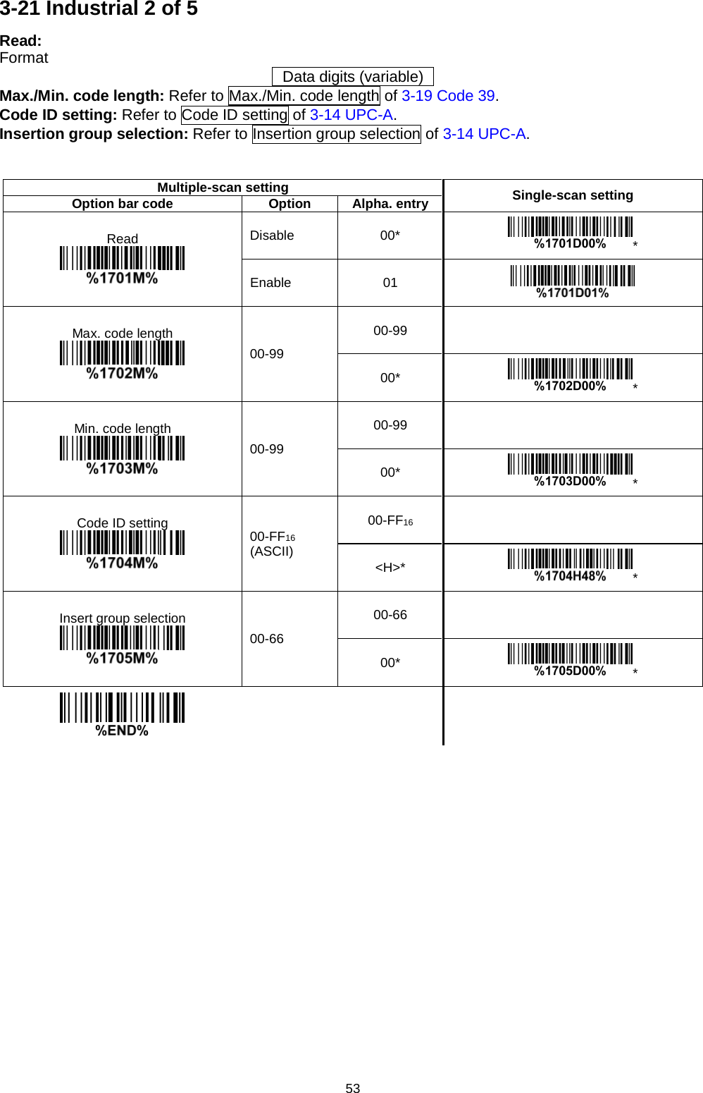
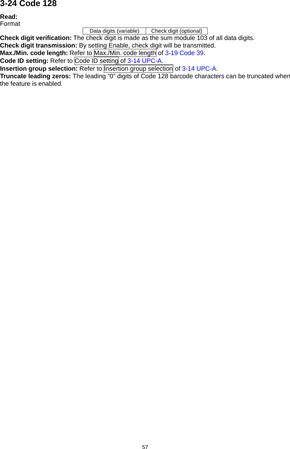
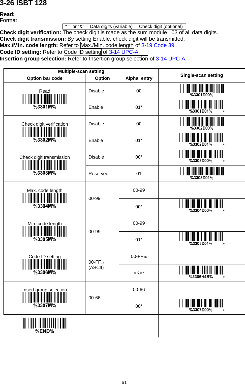
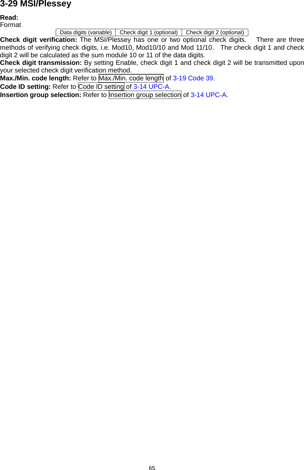
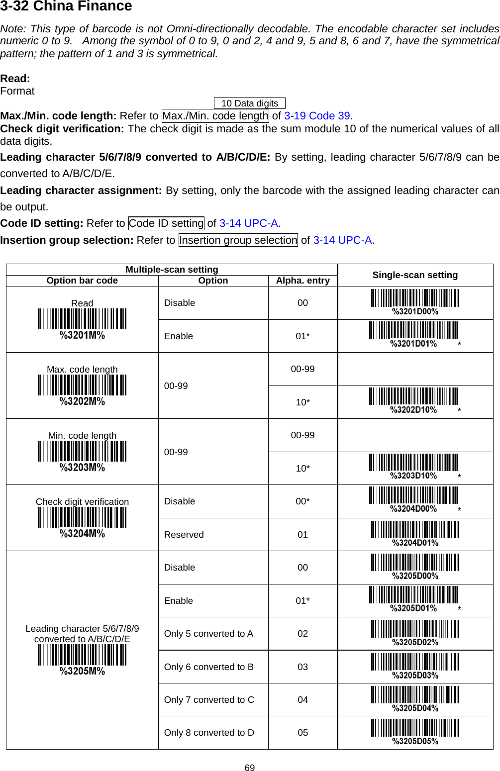
![92 6 ASCII Table for keyboard wedge for RS-232 H L 0 1 0 1 0 Null NUL DLE 1 Up F1 SOH DC1 2 Down F2 STX DC2 3 Left F3 ETX DC3 4 Right F4 EOT DC4 5 PgUp F5 ENQ NAK 6 PgDn F6 ACK SYN 7 F7 BEL ETB 8 Bs F8 BS CAN 9 Tab F9 HT EM A F10 LF SUB B Home Esc VT ESC C End F11 FF FS D Enter F12 CR GS E Insert Ctrl+ SO RS F Delete Alt+ SI US Notes: The 2nd and the 3rd columns above are used for keyboard wedge only. H L 2 3 4 5 6 7 0 SP 0 @ P ` p 1 ! 1 A Q a q 2 “ 2 B R b r 3 # 3 C S c s 4 $ 4 D T d t 5 % 5 E U e u 6 & 6 F V f v 7 ‘ 7 G W g w 8 ( 8 H X h x 9 ) 9 I Y i y A * : J Z j z B + ; K [ k { C , < L \ l | D - = M ] m } E . > N ^ n ~ F / ? O _ o DEL Example: ASCII “A” = “41”.](https://usermanual.wiki/Minde-Electronics-Technology/CS2X90/User-Guide-3867133-Page-102.png)