Minde Electronics Technology CS2X90 Cordless Barcode Scanner User Manual
Shenzhen Minde Electronics Technology LTD. Cordless Barcode Scanner
user manual

CS2290&CS2290-BT Cordless Image
Scanner User Manual
Version: CS2290&CS2290-BT_UM_EN_V1.2.3
i
Notice
Make sure you carefully read the following information to ensure that your barcode scanner is able to
perform at the level for which it is designed.
1) All software, including firmware, furnished to the user is on a licensed basis.
2) The right is reserved to make changes to any software or product to improve reliability, function, or
design.
3) The material in this manual is subject to change without notice.
4) The manufacturer assumes no responsibility for any loss or claims by third parties which may arise
from the use of this manual.
5) A standard kit contains: a handheld unit, a cradle, a USB cable, and a CD-ROM (containing software
and electrical manuals).
6) Do not throw or drop the scanner or otherwise subject it to strong impact, which can damage the
scanner, interrupt program execution, corrupt memory contents, or otherwise interfere with proper
operation.
7) Use a blunt object to operate the stroke keys. Use of a sharp pointed object can damage stroke
keys and cause shorting of internal circuitry.
8) Do not remove the battery from the barcode scanner before you read the instructions carefully.
9) Sudden temperature changes can cause condensation to form on the scanner’s case. Operating
the scanner while condensation is present can interfere with proper operation. Take care to avoid
conditions that cause the formation of condensation. If condensation does form, wait until it dries
completely before using the scanner.
10) If multi-clusters are working in the same area, it is strongly recommended that different radio
frequency channel numbers are applied to different clusters. While setting up, only the radio
frequency channel number of the first handheld unit of a single cluster is required to be set. When
the first handheld unit binds to the cradle, the cradle will automatically obtain the radio frequency
channel number of the handheld unit. The consecutive joined handheld units will automatically
obtain the radio frequency channel number of the cradle.
11) In order to obtain constantly good communication quality, when in multi-clusters working mode, the
physical space between two cradles is required to be at least 2 meters.
12) In order to obtain constantly good communication quality, it is recommended to place the cradle on a
higher location, generally more than 1 meter above the ground. If working outdoor, the higher
location the better.
Note:Article 10 and 11 are only for CS2290

ii
Safety precautions – Danger!
Be sure to read the following safety precautions carefully before trying to use the barcode scanner for
the first time. Keep this manual in handy place for future reference.
Danger!
Lithium-ion battery
1) Never allow the battery to become wet. Water can create the danger of battery heat emission,
explosion, and fire.
2) Never use or leave the battery next to open flame, near a stove, or any other area exposed to
high heat. Doing so creates the danger of battery heat emission, explosion, and fire.
3) Never use the battery with any device other than this unit. Doing so can creates the danger of
battery heat emission, explosion, and fire.
4) Note that the battery’s positive (+) and negative (-) terminals must be oriented correctly when it is
loaded into the Barcode Scanner. Connecting the battery with its terminals reversed creates the
danger of battery fluid leakage, heat emission, explosion, and fire.
5) Never dispose of the battery by incinerating it or otherwise expose it to heat. Doing so creates the
danger of battery heat emission, explosion, and fire.
6) Never allow the positive (+) and negative (-
) terminals of the battery to become connected
(shorted) by metal. Doing so create the danger of battery heat emission, explosion, and fire.
7) N
ever transport or store the battery together with a necklace, hair pins or other metal objects.
Doing so can short battery terminals, and create the danger of battery heat emission, explosion
and fire. Be sure to place the battery in its case whenever transporting or storing it.
8) Never throw the battery or otherwise subject it to strong impact. Dong so creates the danger of
battery heat emission, explosion, and fire.
9) Never pierce the battery with nails, hit it with a hammer, or step on it. Doing so can create the
danger of battery heat emission, explosion, and fire.
10) Never try to take apart the battery in any way. Doing so creates the danger of battery heat
emission, explosion, and fire.
11) Use only the specified charger to charge the battery. Use of other types of charger creates the
danger of battery heat emission explosion, and fire.

iii
Safety precautions – Warning!
Warning!
Disassembly and modification
Never try to disassemble or modify the unit in any way. High voltage inside creates the danger of
electrical shock.
Interior parts and components
Never touch interior high-
voltage parts or components. Doing so creates the danger of electrical
shock.
Abnormal conditions
Should the unit become hot or start to emit smoke or a strange odor, immediately turn off the power
and contact your original dealer. Continued use creates the danger of fire and electrical shock.
Foreign objects
Should any foreign matter ever get into the unit, immediately turn off the power and contact your
original dealer. Continued use creates the danger of fire and electrical shock.
Dropping and damage
Should you drop the unit and damage it, immediately turn off the power and contact your original
dealer. Continue use creates the danger of fire and electrical shock.
Laser beam
Never look directly into the laser beam. Doing so can cause serious eye damage.
Lithium-ion battery
1) Do not put a battery in microwave ovens or pressure cookers. Doing so may cause the battery to
overheat, explode or burst into flames.
2) Do not use a battery that smells strange, is overheating, is a strange color, or is a strange shape.
Doing so may cause the battery to overheat, explode or burst into flames.
3) If the amount of time period the battery can serve becomes considerably short, stop using it. It
may indicate the possibility of a malfunction in the battery. Continued charging the battery creates
the danger of heat emission, explosion, and fire.
4) Stop charging the battery after the recommended time even if it is not fully charged. Continuing to
charge the battery may cause the battery to over heat, explode or burst into flames.
5) If the battery leaks fluid or emits a strange smell, remove it from near heat or flames. Burning may
cause the battery to explode or burst into flames. Should fluid from the battery accidentally get
into your eyes, do not rub them. Immediately rinse your eyes with clean water such as tap water
and then consult a physician immediately.

iv
Cradle with RS-232 cable and adaptor
1) Power the cradle only with a power outlet whose voltage matches that marked on the adaptor
specified in this manual.
2) Avoid conditions that can cause damage or breaks in the power cord. D
o not place heavy
objects on the power cord. Keep it away from sources of heat. Any of these conditions can
damage the power cord, creating the danger of fire and electrical shock.
3) Never modify, sharply bend, twist, or pull on the power cord. Doing so creates the danger of fire
and electrical shock.
4) Use only the AC/DC adaptor and charger specified in this manual. Use of other AC/DC adaptor
models or chargers creates the danger of fire and electrical shock.
5) Should the power cord ever become severely damaged, contact your original dealer. Use of a
damaged electrical cord creates the danger of fire and electrical shock.
Moisture
Keep the Basic Unit and the Barcode Scanner away from vases, planters, cups, glasses and other
containers of liquid. Also keep it away from metal. Water and metal getting into the unit creates the
danger of fire and electrical shock.

v
Safety precautions – Caution!
Caution!
Foreign objects
Take care to ensure that metal or combustible objects are not inserted into the openings of the unit.
Such objects create the danger of fire and electrical shock.
Location
1) Do not locate the unit on a surface that is unstable or uneven. Doing so creates the danger of the
unit falling, which can cause personal injury.
2) Do not locate the unit in an area subjected to large amounts of humidity or dust. Doing so creates
the danger of fire and electrical shock.
3) Do not leave the unit for long periods in a car parked in direct sunlight.
Heavy objects
Never place heavy objects on top of the unit. Doing so creates the risk of a loss of balance and the
object falling, which can cause personal injury.
Scan window
1) Never apply strong pressure to the mirror or subject it to strong impact. Doing so can crack the
mirror and create the danger of personal injury.
2) Should the mirror ever break, never touch the mirror broken. Doing so can cause personal injury.

vi
Lithium-ion battery
1) Never leave the battery in an area expose to direct sunlight, in a car parked in direct sunlight, or
any other very hot area. D
oing so creates the danger of heat emission and fire, as well as
deterioration of battery performance and shortening of its service life.
2) Do not use the battery in areas where static electricity is being generated. Doing so creates the
danger of battery heat emission, explosion, and fire.
3) Temperature ranges for battery use, charging and storage are specified below. Temperatures
outside these ranges create the danger of deterioration of battery performance and shortening of
its service life as well as fluid leakage and heat generation.
4) Operating Temperature: -20℃ to 60℃.
5) Charging Temperature: 0℃ to 45℃.
6) Storage Temperature: -20℃ to 45℃.
7) Should fluid from the battery accidentally get onto clothing or your skin, immediately rinse it off
with clean tap water. Prolonged contact with battery fluid can cause skin irritation.
8) Keep the battery out of the reach of small children. Do not let small children remove the battery
from the charger or the unit it is powering.
Cradle with RS-232 cable and adaptor
1) Keep the power cord away from stoves and other sources of extreme heat. Heat can melt the
insulation of the power cord and create the danger of fire and electrical shock.
2) Never pull on the power cord when unplugging it. Doing so can damage the cord and create the
danger of personal injury, fire and electrical shock. Always hold onto the pug when unplugging it
from the wall outlet.
3) Never touch the plug while your hands are wet. Doing so can create the danger of electrical
shock.
4) Be sure to unplug the power cord from the wall outlet before moving the Basic Unit. Failure to do
so can result in damage to the power cord caused by pulling it, which creates the danger of fire
and electrical shock.
5) Be sure to unplug the power cord from the wall outlet before cleaning the Basic Unit and charger.
6) Be sure to turn the power off and unplug the power cord after use.
7) Unplug the power cord from the wall outlet and clean the area around the plugs at least once a
year. I
f dust collects on the AC/DC adaptor, humidity or moisture may cause a fault in the
insulation, which may result in a fire.
vii
Contents
1 Specifications ........................................................................................................................................ 1
1-1 Technical specifications .................................................................................................................... 1
1-2 Default setting for each barcode ...................................................................................................... 3
2 Get started .............................................................................................................................................. 4
2-1 Cable connector pin-outs descriptions for cradle ............................................................................. 4
2-2 Dimensions ....................................................................................................................................... 5
2-3 Parts of the scanner ......................................................................................................................... 6
2-4 Charge battery .................................................................................................................................. 7
2-5 Installation of cradle.......................................................................................................................... 8
2-5-1 PS/2 keyboard cable ................................................................................................................. 8
2-5-2 USB cable .................................................................................................................................. 8
2-5-3 RS-232 cable ............................................................................................................................. 8
3 Progamming menus .............................................................................................................................. 9
3-1 Example 1: Single-parameter setting by scanning 1D barcodes ..................................................... 9
3-2 Example 2: Multiple-parameter setting by scanning a QR code barcode ..................................... 10
3-3 CS2290 Wireless communication setting ....................................................................................... 11
3-3-1 Wireless communication setting for handheld unit ................................................................... 11
3-3-2 example ................................................................................................................................... 12
3-4 CS2290-BT Wireless communication setting ................................................................................. 16
3-4-1 example ................................................................................................................................... 16
3-5 Batch data mode ............................................................................................................................ 17
3-6 Keyboard wedge interface for cradle ............................................................................................. 18
3-7 RS-232 interface for cradle ............................................................................................................ 22
3-8 USB interface for cradle ................................................................................................................. 24
3-9 Handheld scan & some global settings .......................................................................................... 27
3-10 Indication for handheld unit .......................................................................................................... 32
3-11 Decode illumination and decode aiming pattern .......................................................................... 33
3-12 Single type of barcode read ......................................................................................................... 35
3-13 DPM, Multiple symbols, Structured append read, etc. ................................................................. 36
3-14 UPC-A........................................................................................................................................... 38
3-15 UPC-E........................................................................................................................................... 40
3-16 UPC-E1......................................................................................................................................... 42
3-17 EAN-13 (ISBN/ISSN) .................................................................................................................... 44
3-18 EAN-8 ........................................................................................................................................... 46
3-19 Code 39 (Code 32, Trioptic Code 39) .......................................................................................... 48
3-20 Interleaved 2 of 5 .......................................................................................................................... 51
3-21 Industrial 2 of 5 ............................................................................................................................. 53
3-22 Matrix 2 of 5 .................................................................................................................................. 54
3-23 Codabar ........................................................................................................................................ 55
3-24 Code 128 ...................................................................................................................................... 57
3-25 UCC/EAN 128 .............................................................................................................................. 59
3-26 ISBT 128 ....................................................................................................................................... 61
3-27 Code 93 ........................................................................................................................................ 62
3-28 Code 11 ........................................................................................................................................ 63
3-29 MSI/Plessey .................................................................................................................................. 65
3-30 UK/Plessey ................................................................................................................................... 67
3-31 China Post .................................................................................................................................... 68
3-32 China Finance .............................................................................................................................. 69
3-33 GS1 DataBar (GS1 DataBar Truncated) ...................................................................................... 71
3-34 GS1 DataBar Limited ................................................................................................................... 72
3-35 GS1 DataBar Expanded ............................................................................................................... 73
3-36 PDF417......................................................................................................................................... 74
3-37 MicroPDF417 ................................................................................................................................ 75
3-38 QR Code ....................................................................................................................................... 76
3-39 Data Matrix ................................................................................................................................... 77
3-40 Aztec Code ................................................................................................................................... 78
3-41 G1-G6 & C1-C2 & FN1 substitution string setting ....................................................................... 79
3-42 G1-G4 string position & Code ID position .................................................................................... 83
3-43 String transmission ....................................................................................................................... 84
viii
4 Test barcode symbols ......................................................................................................................... 87
5 Maintenance ......................................................................................................................................... 91
6 ASCII Table ........................................................................................................................................... 92
7 Barcode representing non-printable character ............................................................................... 93
8 Return default parameters.................................................................................................................. 94
8-1 CS2290 return default parameters ................................................................................................. 94
8-2 CS2290-BT return default parameters ........................................................................................... 95
9 Display firmware version & radio communication setting ............................................................. 96
9-1 CS2290 display firmware version & radio communication setting ................................................. 96
9-2 CS2290-BT display firmware version ............................................................................................. 97
10 Configuration alphanumeric entry barcode ................................................................................... 98

1
1 Specifications
1-1 Technical specifications
Handheld unit
CS2290 CS2290-BT
Radio Link
430.0
~
431.9 MHz, 433.3
~
434.7 MHz
with adaptive frequency hopping
2.4-2.5GHz, Bluetooth 4.0, Class 2
Working Range
100 meters (open air); 30 meters (open air)
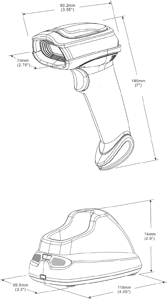
Dimensions Length × Width × Depth: 90.2 × 70 × 180 mm
Weight
225 g
Color Gray
Indicator LED, Beeper, Vibrator
Operating Mode Handheld
Programming
Method
Manual (reading special barcode)
Program Upgrade Using Flash Utility software, while a cradle unit is required.
Input Voltage 5 ± 0.25 VDC
Current 20 mA (standby), 350 mA (scanning)
Battery 2600 mAh Lithium-ion battery
Charge Time 6 hours
Standby Time 6.5 days
Working Time 70 hours (1 scan per 5 seconds)
Image Size 1280 × 800 pixels
Field of View Horizontal: 42°, vertical: 26.5°
Scanning Angle ±70°, ±75°, 360° (Skew, Pitch, Roll)
Print Contrast 20% minimum reflectance difference
Decoding Capability
1D:
UPC-A, UPC-E, UPC-E1, EAN-13, EAN-
8, ISBN (Bookland EAN), ISSN,
Code 39, Code 39 full ASCII, Code 32, Trioptic Code 39, Interleaved 2 of 5,
Industrial 2 of 5, Matrix 2 of 5, Codabar (NW7), Code 128, UCC/EAN 128,
ISBT 128, Code 93, Code 11 (USD-8), MSI/Plessey, UK/Plessey, China Post,
China Finance, GS1 DataBar (formerly RSS) variants
2D:
PDF417, MicroPDF417, QR code, DataMatrix, Aztec Code
Minimum
Resolution
HD: 1D (Code 39): 3 mil, 2D (QR): 5 mil
SR: 1D (Code 39): 4 mil, 2D (PDF417): 6.7 mil
Decoding Depth
High desity series
(HD)
Standard range
series (SR)
3 mil Code39 (3 chars) 10 mm – 61 mm /
4 mil Code 128 (9 chars) 5 mm – 88 mm 55 mm – 106 mm
5 mil Code39 (3 chars) 0 mm – 108 mm 43 mm – 141 mm
10 mil Code39 (3 chars) 0 mm – 167 mm 0 mm – 310 mm
13 mil UPC (6 chars) 0 mm – 179 mm 0 mm – 335 mm
20 mil Code39 (1 char) 10 mm – 253 mm 8 mm – 480 mm
5 mil QR (40 chars) 7 mm – 65 mm /
6.7 mil PDF417 (20 chars) 0 mm – 105 mm 37 mm – 145 mm

2
10 mil QR (20 chars) 0 mm – 134 mm 0 mm – 168 mm
20 mil QR (20 chars) 0 mm – 215 mm 0 mm – 345 mm
Temperature
0° to 50°C (32° to 120°F), operating
-40° to 60°C (-40° to 140°F), storage
Humidity 5% to 95% (non-condensing)
Safety
EMC: EN55022, EN55024
Electrical Safety: EN60950-1
Photobiological Safety: EN62471:2008
Illumination: 0~100,000 LUX
Protection Class: IP51
Drop Resistance: Withstands multiple 1.5 m (5 ft.) drops to concrete
Note: Test condition: temperature at 27°C, sunny day, and visibility of 5 kilometers. Natural
surroundings significantly affect the communication distance in practice. The distance drops quickly in
the rainy, high-humidity, or heavy haze day; radio interference also shortens the communication
distance.
Cradle
Input Voltage 5 ± 0.25 VDC
Current 60 mA (working), 500 mA (charging)
Cable Straight 2.0 m (PS/2) / Straight 1.5 m (USB) / Straight 2.0 m (RS-232 )
Dimensions Length × Width × Depth: 118 × 89.5 × 74 mm
Weight 140 g (without cable)
Indicator LED
Programming
Method
Manual (reading special barcode)
Program Upgrade PC online using Flash Utility software.
Temperature
0° to 50°C (32° to 120°F), operating
-40° to 60°C (-40° to 140°F), storage
Humidity 5% to 95% (non-condensing)
Drop Resistance Unit functions normally after repeated 1.5 m (5 ft.) drops to concrete

3
1-2 Default setting for each barcode
Code type Read
enable Check digit
verification Check digit
transmission
Min. code
length
Proprietar
y
code ID
AIM
code ID
UPC-A √ √ √ (12)2 A ]Em
UPC-E √ √ √ (8)2 D ]Em
UPC-E1 √ √ √ (8)2 D ]Em
EAN-13 √ √ √ (13)2 A ]Em
EAN-8 √ √ √ (8)2 C ]Em
ISBN (Bookland EAN)
/ ISSN1 √ √ √ (13)2 B ]Em
Code 39 √ - - 1 M ]Am
Interleaved 2 of 5 √ - - 6 I ]Im
Industrial 2 of 5 - - - 4 H ]Im
Matrix 2 of 5 √ - - 6 X ]Im
Codabar √ - - 4 N ]Fm
Code 128 √ √ - 1 K ]Cm
ISBT 128 √ √ - 1 K ]Cm
Code 93 √ √ - 1 L ]Gm
Code 11 - √ - 4 V -
MSI/Plessey - - - 4 O ]Mm
UK/Plessey - √ - 1 U ]Mm
UCC/EAN 128 √ √ - 1 K ]Cm
China Post √ - - (11)2 T ]Im
China Finance √ - - (10)2 Y -
GS1 DataBar √ - - (16)2 R ]em
GS1 DataBar
Truncated3
√ - - (16)2 R ]em
GS1 DataBar Limited √ - - (16)2 R ]em
GS1 DataBar Expanded
√ - - 1 R ]em
PDF417 √ - - - - -
MicroPDF417 √ - - - - -
DataMatrix √ - - - - -
QR code √ - - - - -
Aztec Code √ - - - - -
Note: 1The settings for ISBN/ISSN and EAN-13 must be the same except the code ID.
2 Fixed-length barcodes.
3The settings for GS1 DataBar Truncated and GS1 DataBar must be the same.
4
2 Get started
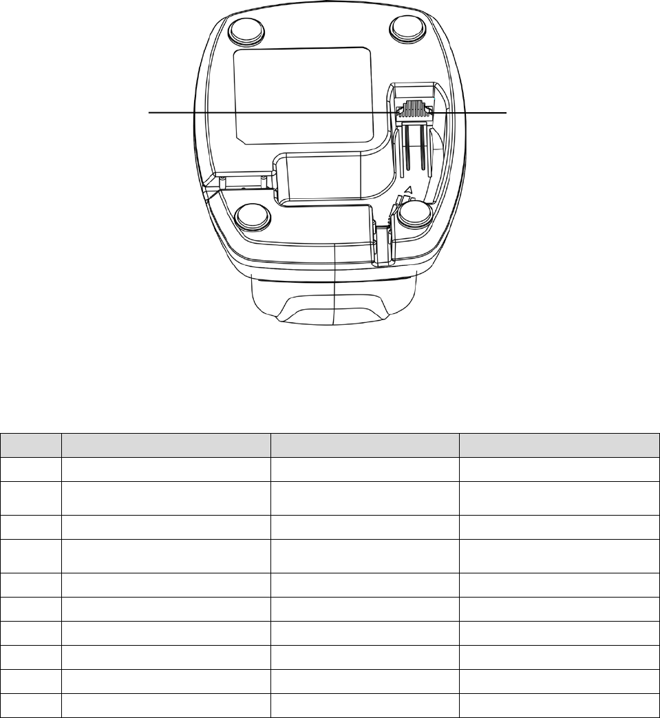
2-1 Cable connector pin-outs descriptions for cradle
Figure 2-1 Cable connector interface pin-outs
The pin-outs descriptions in Table 2-1 apply to the cable connector on the cradle and are for reference
only. Table 2-1 Cable connector pin-outs descriptions
Pin
RS232
Keyboard (PS/2)
USB
1
Power (+5V)
Power (+5V)
Power (+5V)
2
+3.3V ( for interface auto
selection purpose)
Ground (for interface auto
selection purpose)
+3.3V ( for interface auto
selection purpose)
3
Ground
Ground
Ground
4
+3.3V ( for interface auto
selection purpose)
Reserved
Ground (for interface auto
selection purpose)
5
TxD
KeyClock
Reserved
6
RxD
KeyData
Reserved
7
Reserved
TermClock
Reserved
8
Reserved
TermData
Reserved
9
CTS
Reserved
D-
10
RTS
Reserved
D+
Note: Voltage level of all RS232 Pin-outs (RxD, TxD, CTS and RTS) is 0V for logic low and 3.3V for logic
high.
Pin 1 Pin 10
5
2-2 Dimensions
6
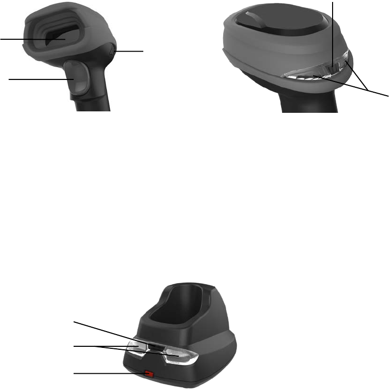
2-3 Parts of the scanner
Figure 2-2 Handheld unit
① Scan window
② Trigger (Press to triggr / Long press 3 seconds to turn on)
③ Beeper
④ On base indicator (Blue LED)
⑤ Successful decoding indicator (Green LED) / Communication fail indicator (Red LED) / Charging
indicator (Red/Green LED)
Figure 2-3 Cradle
⑥ Power indicator (Blue LED)
⑦ Communication indicator (Green LED)
⑧ Key (Long press 10 seconds to restore factory default setting of cradle)
①
②
③
⑤
④
⑥
⑦
⑧

7
2-4 Charge battery
1. Please charge the battery before the first time of use. The charge indicator (red LED) on the
handheld unit is turned on when the charging is in process. When the charging process completes,
the red LED is turned off.
2. Charging time: 6 hours for fully charged.
3. You can charge the battery via a USB port on the device or a 5 VDC power adapter.
Note: The 5 VDC power adapter is an optional accessory.
Figure 2-4
8
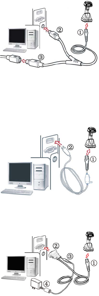
2-5 Installation of cradle
Note: If any of the below operation is incorrect, turn off the power immediately and check the scanner for
any improper connections. Go through all steps again.
2-5-1 PS/2 keyboard cable
Plug one end of the PS/2 keyboard cable to the cradle, one end to PS/2 port on PC, and one end to the
keyboard.
2-5-2 USB cable
1) Plug one end of the USB cable to the cradle. Plug the other end into the USB port of the computer.
2) Windows gives message on “new hardware found – USB HID input device found”, then driver will be
installed on request.
3) After successfully installing the new hardware, message will be given: “hardware installed
successfully and ready to use”.
4) If any problem encounters during the installation process, please unplug the USB cable from the
computer and repeat step 1) and 2).
2-5-3 RS-232 cable
1) Connect the DB9 serial communication cable with the cradle and the COM port of the computer.
2) Plug the output of the AC/DC adaptor into the power terminal of on the cradle. Plug the AC/DC
adaptor provided by the manufacturer into an electrical outlet.
9
3 Progamming menus
3-1 Example 1: Single-parameter setting by scanning 1D barcodes
Important notes:
1. During the process of programming, LED is lighting to indicate the programming correctness. LED
will go off if any incorrect programming operation performed.
2. After each successful programming, LED will go off and the scanner will beep twice.
3. Throughout the programming barcode menus, the factory default settings are indicated with
asterisks (*).
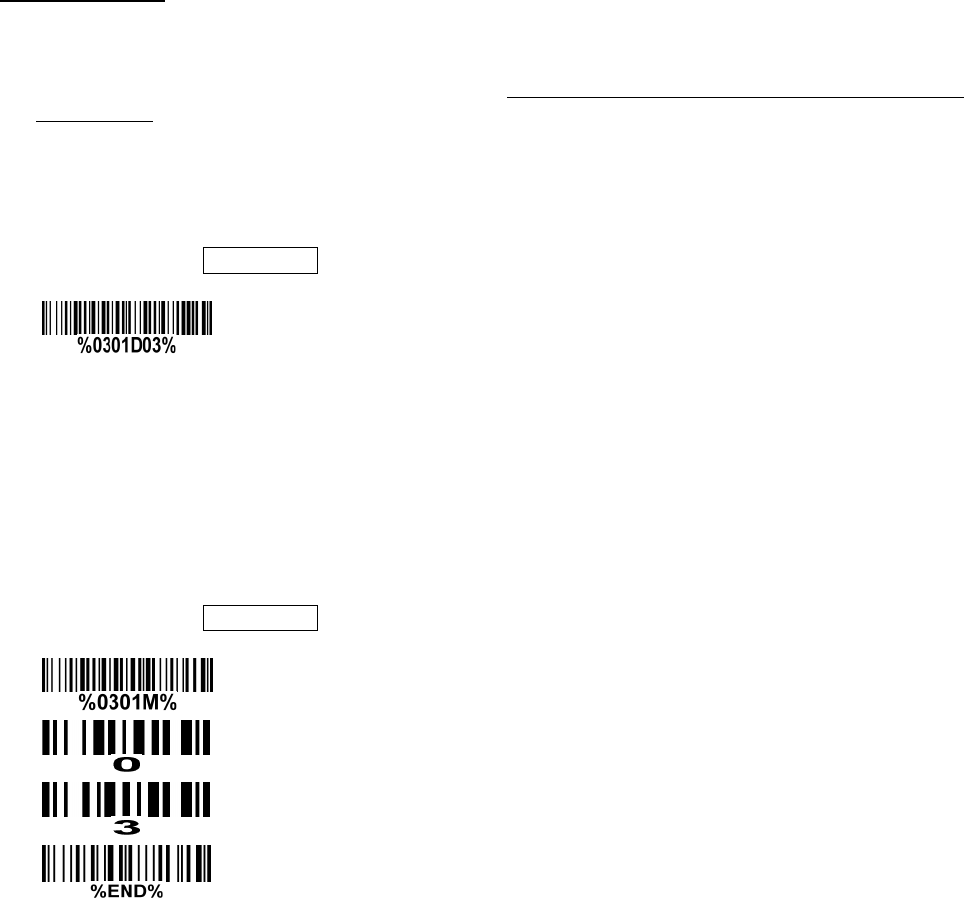
Two programming modes have been provided as bellows:
❶ Single-scan setting
Scan the appropriate Single-scan setting (e.g. %0101D00%) according to the user‘s demand.
Example: To set Flow control to be XON/XOFF.
Steps: Scan the following barcode.
❷ Multiple-scan setting
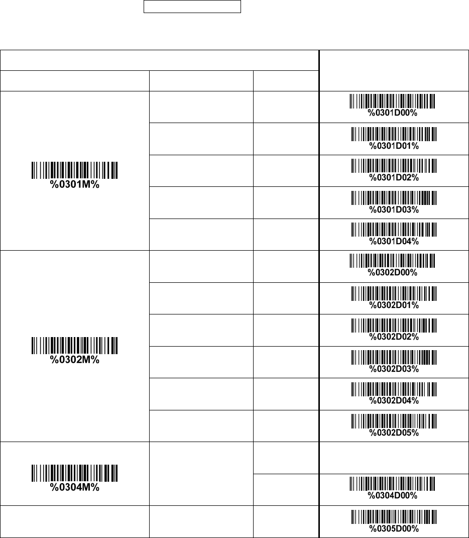
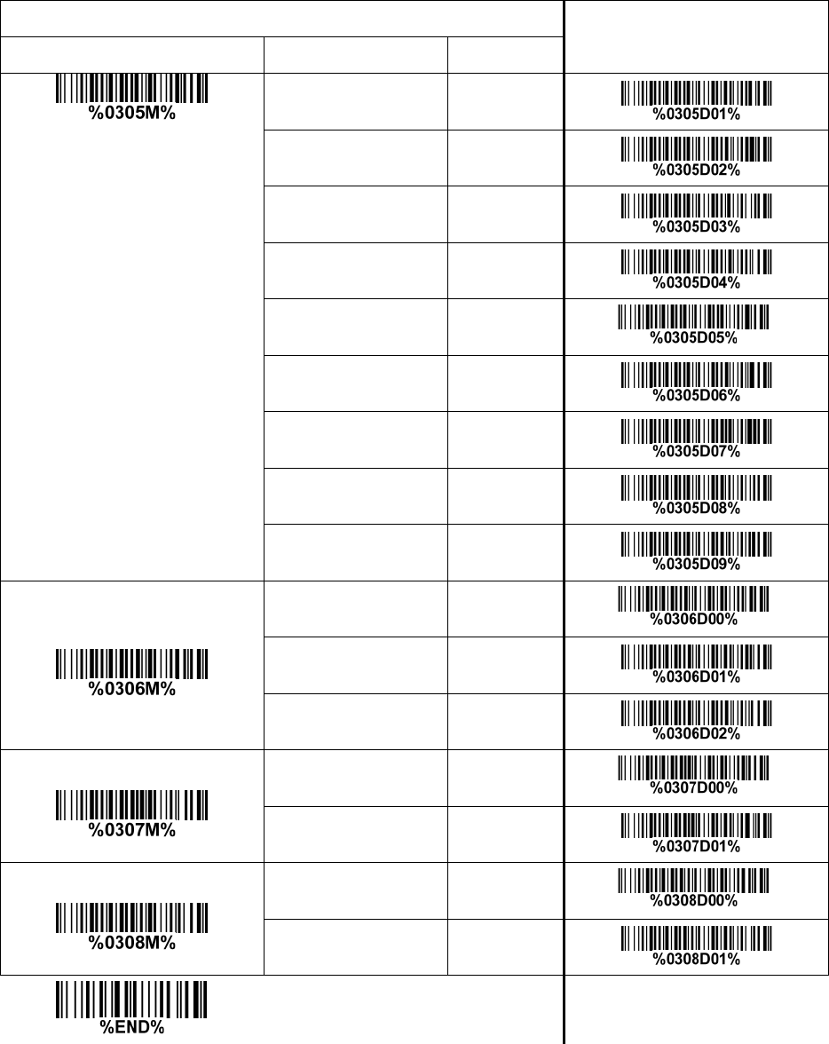
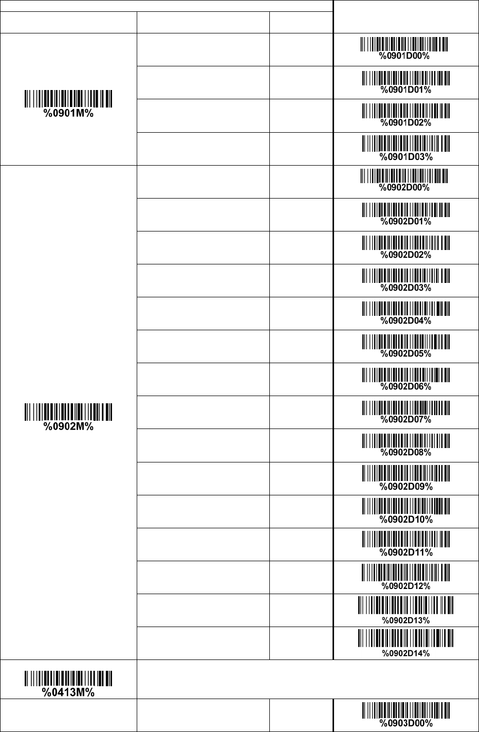
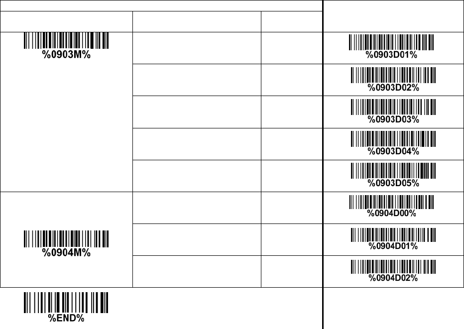
Step 1. Scan the Option barcode barcode (e.g. %0101M%) according to the user‘s demand.
Step 2. To the right of the option barcode, the necessary alphanumeric inputs are listed. Scan
two alphanumeric entries from 0 to 9 or A to F, refer to 10 Configuration alphanumeric entry
barcode.
Step 3. Repeat Step 2, if more user parameters input are required.
Step 4. Scan the %END% barcode, listed on the lower left hand corner of each parameter
setting part.
Example: To set Flow control to be XON/XOFF.
Steps: Referring to 3-7 RS-232 interface for cradle, scan the following barcodes in order.
10
3-2 Example 2: Multiple-parameter setting by scanning a QR code
barcode
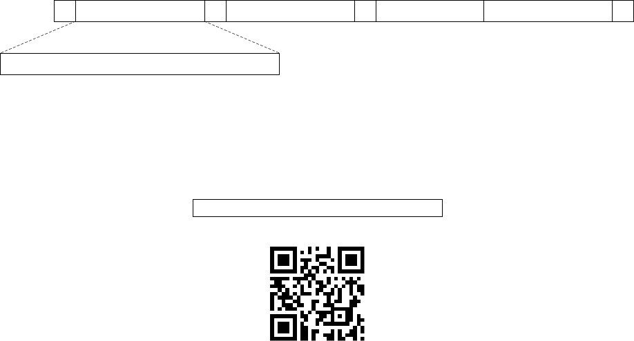
User can customize a QR code barcode to set multiple parameters. The scanner can set multiple
parameters by scanning this single QR code barcode.
1. The data format of the QR code barcode is as following.
%Param eter set 1%P aram eter set 2%P aram eter set N %
<O ption barcode index><D/H><Alpha. entries>
···
Note that:
<Option barcode index> means the corresponding 4 digits of Option barcode.
<D/H> means “D” or “H” character. D means that the type of alphanumeric entry is decimal; and H
means that the type of alphanumeric entry is hexadecimal.
<Alpha. entries> is a character string with various length of 2, 4, or other values.
Example: Set 0401->03 (decimal); 8002->0D0A (hexadecimal); 8202->01 (decimal). The customized
QR code barcode contents and symbol are as following.
%0401D03%8002H0D0A%8202D01%
2. Notes of making QR code barcode
The model is chosen as M2. Other requirements, e.g. ECC level, Start mode, etc, are not specified.
Other notes
1- The contents of a QR code barcode can include several same <Option barcode index> associated
with same or different <Alpha. entries>. In the case of with different <Alpha. entries>, the latest
<Alpha. entries> is the valid one.
2- If any one of the parameter settings is invalid, the total setting is failed. The invalid setting can be
caused by one of the following problems: invalid <Option barcode index>, invalid type of <D/H>,
invalid type, length or value range of <Alpha. entries>, etc.
11
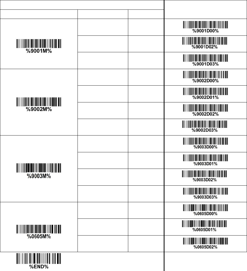
3-3 CS2290 Wireless communication setting
3-3-1 Wireless communication setting for handheld unit
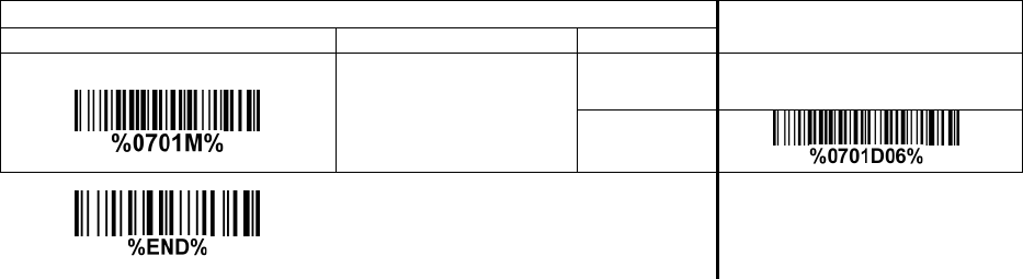
Handheld unit RF channel No.: The scanner offers 16 different radio frequency channels for the data
transmission between handheld unit and cradle. The number of channel can be increased.
Multiple-scan setting
Single-scan setting
Option bar code
Option
Alpha. entry
Handheld unit RF channel No.
02-16
02-16
06*
*
12
3-3-2 example
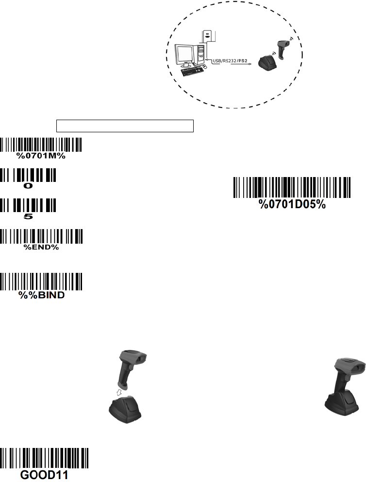
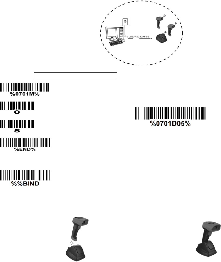
Example 1: One handheld unit and one cradle
The following takes channel No.5 for instance.
Step 1): Set Handheld unit RF channel No. of the handheld unit to 5.
or
Step 2): Scan the following barcode to bind the handheld unit with the cradle.
Firmly position the handheld unit onto the cradle. Within 10 seconds, two beeps will be emitted to
signal that the cradle has been paired to the handheld unit, and the blue LED on the handheld unit will
go off. If three beeps are emitted, it indicates unsuccessful pairing between the cradle and the
handheld unit, then repeat step 2).
Test barcode:
13
Example 2: Two handheld units and one cradle
The following takes channel No.5 for instance.
Step 1): Set Handheld unit RF channel No. of the first handheld unit to 5.
or
Step 2): Make the first handheld unit scan the following barcode to bind the handheld unit with the
cradle.
Firmly position the handheld unit onto the cradle. Within 10 seconds, two beeps will be emitted to
signal that the cradle has been paired to the handheld unit, and the blue LED on the handheld unit will
go off. If three beeps are emitted, it indicates unsuccessful pairing between the cradle and the
handheld unit, then repeat step 2).
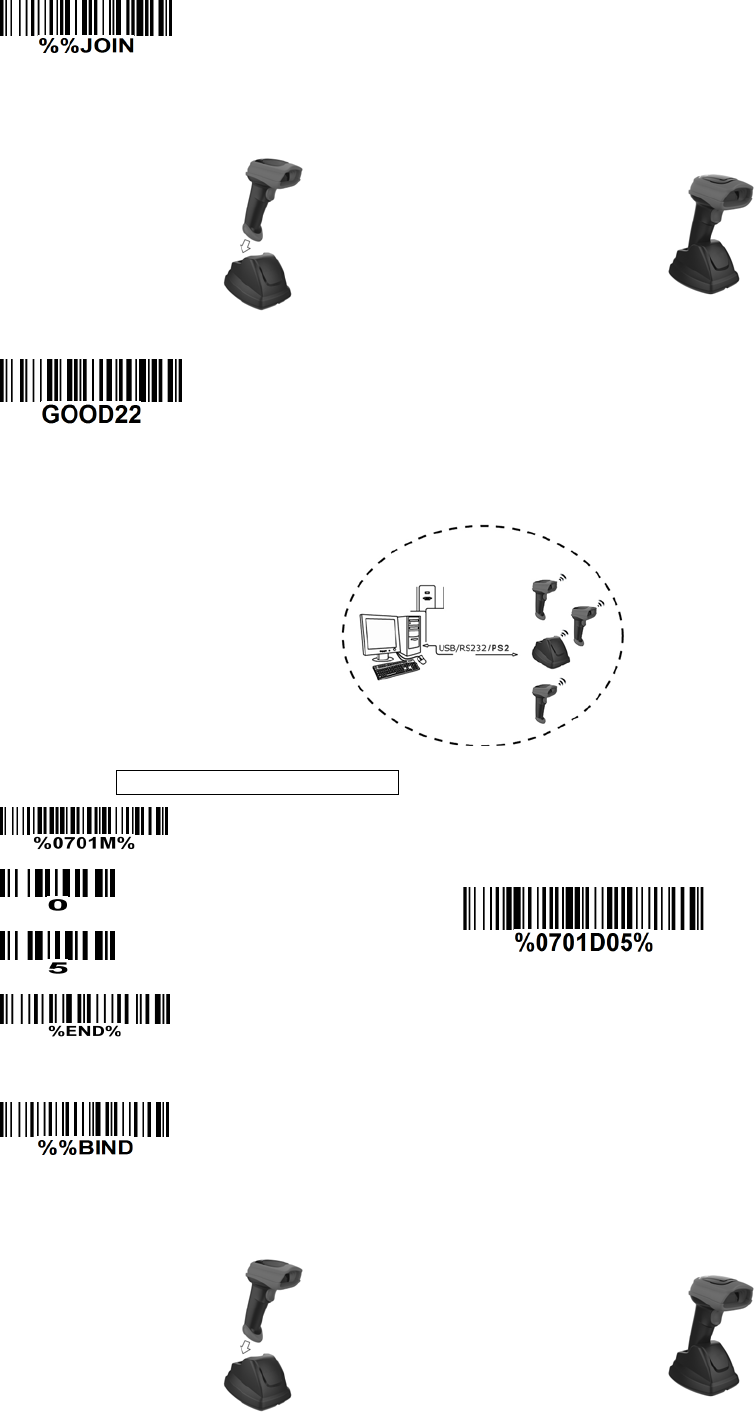
14
Step 3): Make the second huandhend unit scan %%JOIN barcode to pair the second handheld unit
with the cradle.
Firmly position the handheld unit onto the cradle. Within 10 seconds, two beeps will be emitted to
signal that the cradle has been paired to the handheld unit, and the blue LED on the handheld unit will
go off. If three beeps are emitted, it indicates unsuccessful pairing between the cradle and the
handheld unit, then repeat step 3).
Test barcode:
Example 3: Three handheld units and one cradle
The following takes channel No.5 for instance.
Step 1): Set Handheld unit RF channel No. of the first handheld unit to 5.
or
Step 2): Make the first handheld unit scan the following barcode to bind the handheld unit with the
cradle.
Firmly position the handheld unit onto the cradle. Within 10 seconds, two beeps will be emitted to
signal that the cradle has been paired to the handheld unit, and the blue LED on the handheld unit will
go off. If three beeps are emitted, it indicates unsuccessful pairing between the cradle and the
handheld unit, then repeat step 2).
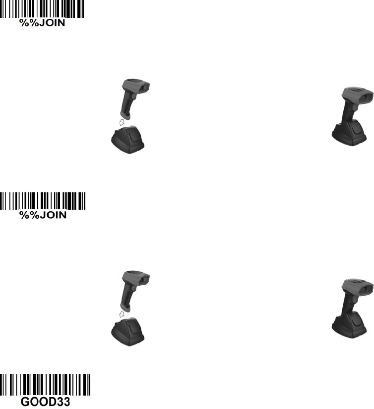
15
Step 3): Make the second huandhend unit scan %%JOIN barcode to pair the second handheld unit
with the cradle.
Firmly position the handheld unit onto the cradle. Within 10 seconds, two beeps will be emitted to
signal that the cradle has been paired to the handheld unit, and the blue LED on the handheld unit will
go off. If three beeps are emitted, it indicates unsuccessful pairing between the cradle and the
handheld unit, then repeat step 3).
Step 4): Make the third huandhend unit scan %%JOIN barcode to pair the third handheld unit with the
cradle.
Firmly position the handheld unit onto the cradle. Within 10 seconds, two beeps will be emitted to
signal that the cradle has been paired to the handheld unit, and the blue LED on the handheld unit will
go off. If three beeps are emitted, it indicates unsuccessful pairing between the cradle and the
handheld unit, then repeat step 4).
Test barcode:
16
3-4 CS2290-BT Wireless communication setting
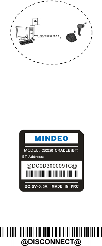
3-4-1 example
The handheld terminal shall ensure that the connection of the base and PC is successful before
communicating with the base.
Connect the base:
The handheld terminal scans the connection barcode at the bottom of the base, and the handheld
terminal will attempt to connect to the base, at the same time ,the handheld terminal will make a
beep-beep-beep sound. If the connection is successful, the handheld terminal can be used directly. If the
connection is unsuccessful, the handheld terminal will make a beep—beep— sound, and the red LED on
the handheld will blinks 2 times, and then turns off.
Disconnect:
The handheld terminal scan disconnects the bar code, and the handheld terminal can be disconnected
from the base
17
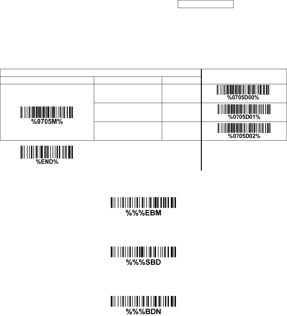
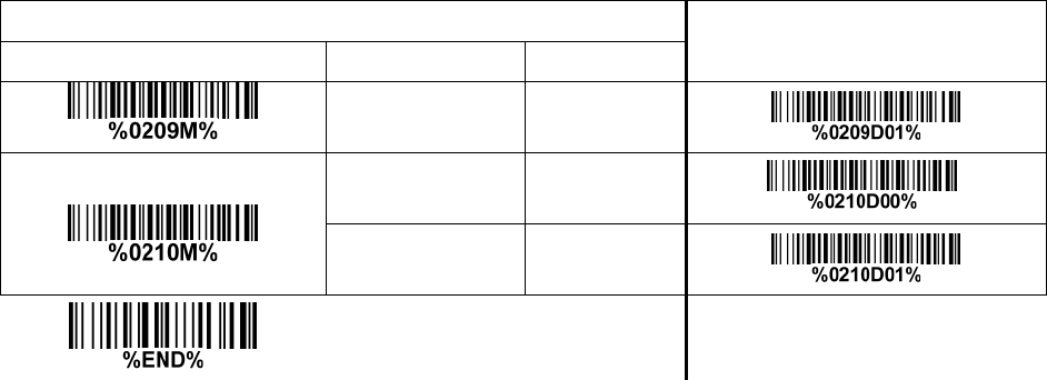
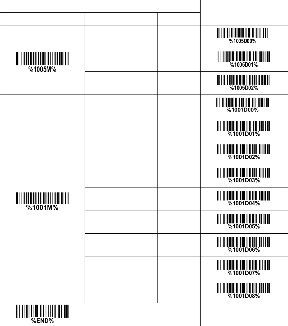
3-5 Batch data mode
Disable- Do not batch data. The handheld unit attempts to transmit every scanned barcode. If the
transmission is failed, the barcode data is ignored.
Out-of-range batch- The handheld unit starts storing barcode data when it loses its connection to a
remote device (for example, when a user holding the handheld unit walks out of range). Data
transmission is triggered by reestablishing the connection with the cradle (for example, when a user
holding the handheld unit walks back into range).
Standard batch- The handheld unit starts storing barcode data after %%%EBM” (Enter Batch Mode)
is scanned. Data transmission is triggered by scanning “%%%SBD” (Send Batch Data).
If you wish to output the total number of barcodes scanned when in Standard batch Mode, scan“%%%BDN”.
In Out-of-range batch or Standard batch modes, calculate the number of barcodes the handheld unit
can store as follows:
Number of storable barcodes = 524,288 bytes of memory / (number of characters in the barcode + 2).
Multiple-scan setting
Single-scan setting
Option bar code
Option
Alpha. entry
Batch data mode
Disable 00* *
Out-of-range batch 01
Standard batch 02
Enter batch mode
Send batch data
Total Records

18
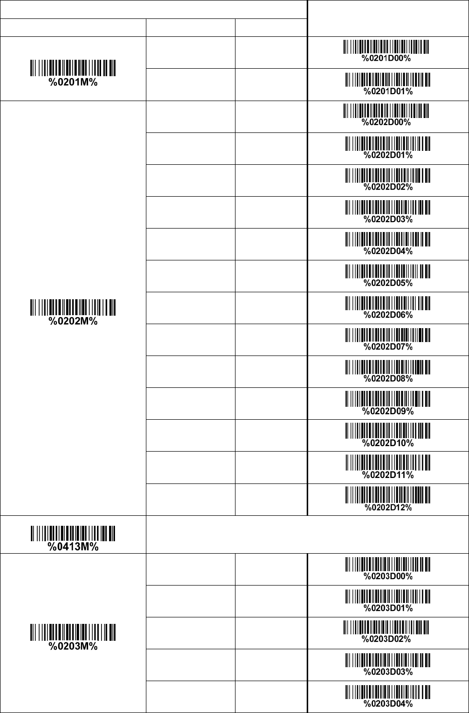
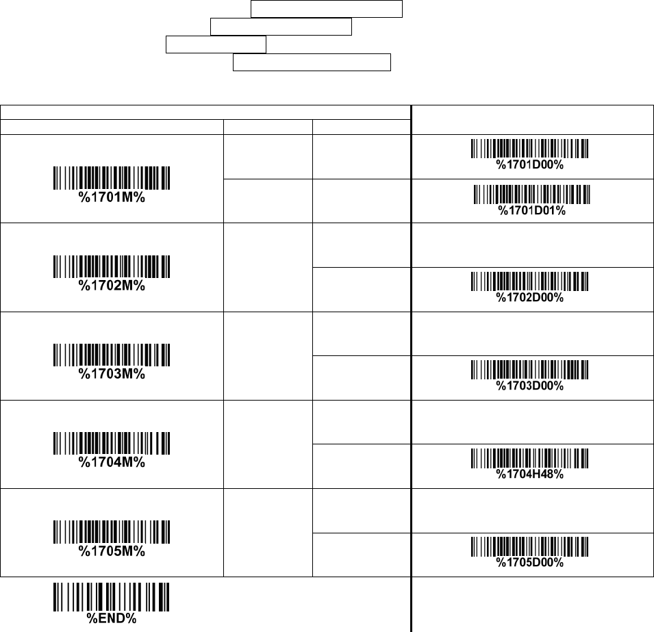
3-6 Keyboard wedge interface for cradle
Keyboard type: As a keyboard interface, the scanner supports most of the popular PCs and IBM
terminals.
Keyboard layout: The scanner supports different national keyboard layouts.
Clock period: According to the PS2 protocol, the clock is provided by the device, e.g. keyboard or
scanner, with the period between 60us to 100us.
Delay-after-compound-key: In some rare occasions, machine with low speed PS2 communication port
would require a free time gap following the press/release of the compound key (Shift, Ctrl or Alt).
Numeric key:
Alphabetic key- The scanner will output code result as alphabetic key.
Numeric key- The scanner will output code result as pressing numeric keypad ( ‘0’, ‘1’, ‘2’, ‘3’, ‘4’, ‘5’,
‘6’, ‘7’, ‘8’, ‘9’, ‘.’, ‘+’, ‘-‘, ‘/’, ‘*’ only).
Alt + keypad- The scanner will output code result as pressing Alt+ numeric key (on keypad). Note
that the Num Lock control key must be ON. This setting can be specially adapted for use with
different national keyboard layout.
Power-on simulation: All of the PCs check the keyboard status during power-on self test. It simulates
keyboard timing and passes keyboard present status to the PC during power-on.
Inter-character delay: This delay is inserted after each data character transmitted.
Inter-byte delay: This delay is inserted after each byte transmitted. Normally a character is comprised
of three or above bytes.
Block trans. delay: It is a delay timer between barcode data output. This feature is used to transfer
continually with shorter barcode data.
Caps Lock reversion: By setting enable, the status of Caps Lock key (i.e. being pressed ON or OFF) on
the keyboard is simulated in a reversion status.
Caps Lock override: If this function is enabled, on AT or AT notebook hosts, the keyboard ignores the
state of the Caps Lock key. Therefore, an ‘A’ in the bar code is sent as an ‘A’ no matter what the state of
the keyboard’s Caps Lock key.
A guide of setting while the scanned data is incorrectly displayed on the host
If some characters are missed or some additional characters are incorrectly displayed on the host,
set the Inter-byte delay (0208) to be “01” or greater value.
If some capital character (e.g. “A”) or compound-key-characters (e.g.“shift+”, “Ctrl+”, “Alt+”)are
displayed incorrectly, set the Delay-after-compound-key to be “01” or greater value.
If some digits are incorrectly displayed as some symbol characters (e.g. “1” and “2” are displayed
incorrectly as “!” and “@”), set the Clock period (0203) to be greater value (e.g. 04, 05).
19
Multiple-scan setting Single-scan setting
Option bar code Option Alpha. entry
Keyboard type
IBM AT, PS/2 00* *
Apple Mac
compatibles 01
Keyboard layout
USA 00* *
Turkish F 01
Turkish Q 02
French 03
Italian 04
Spanish 05
Slovak 06
Denmark 07
Japanese 08
German 09
Belgian 10
Russian 11
Czech 12
Character encoding system
Refer to 3-9 Handheld scan & some global settings.
Clock period
60 us 00
70 us 01
80 us 02* *
90 us 03
100 us 04
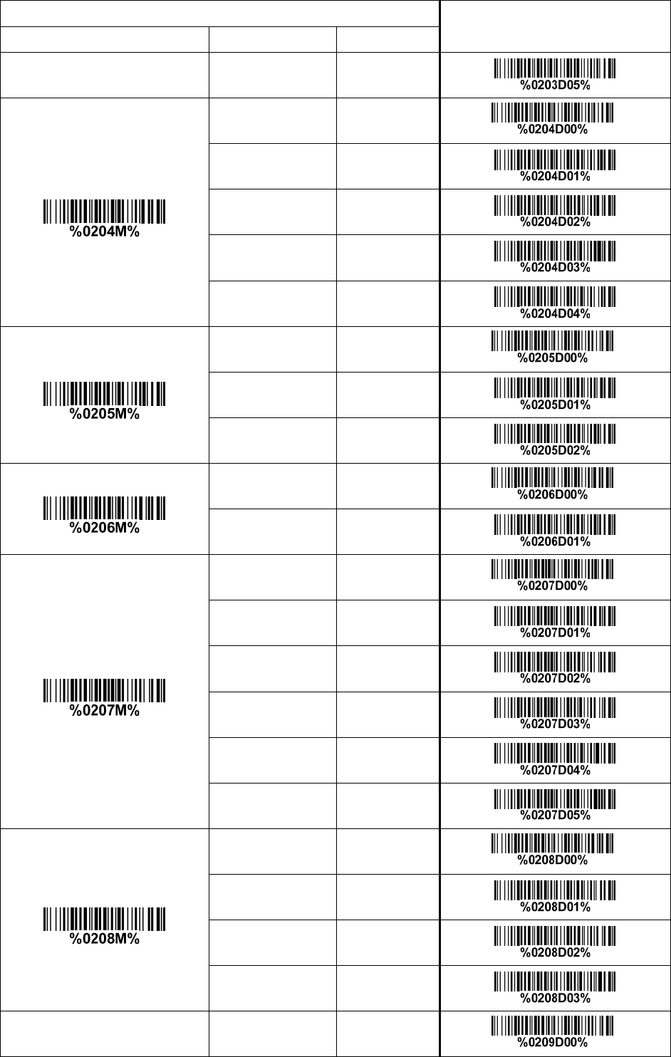
20
Multiple-scan setting Single-scan setting
Option bar code Option Alpha. entry
200 us 05
Delay-after-compound-key
0 ms 00* *
10 ms 01
20 ms 02
40 ms 03
80 ms 04
Numeric key
Alphabetic key 00* *
Numeric keypad 01
Alt + keypad 02
Power-on simulation
Disable 00* *
Enable 01
Inter-character delay
0 ms 00* *
5 ms 01
10 ms 02
20 ms 03
40 ms 04
80 ms 05
Inter-byte delay
1 ms 00* *
2 ms 01
4 ms 02
8 ms 03
Caps Lock reversion Disable 00* *
21
Multiple-scan setting Single-scan setting
Option bar code Option Alpha. entry
Enable 01
Caps Lock override
Disable 00* *
Enable 01
22
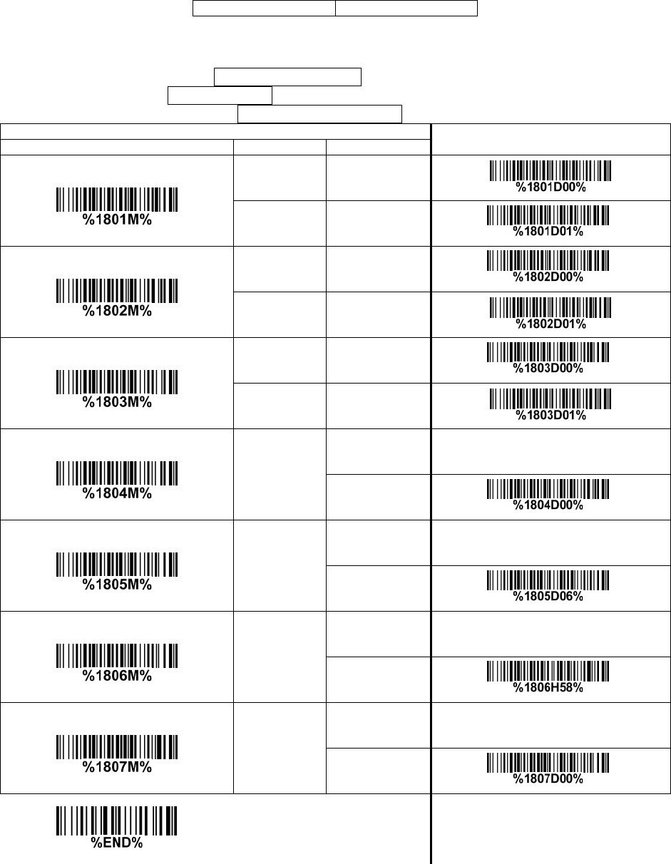
3-7 RS-232 interface for cradle
Flow control:
None-The communication only uses TxD and RxD signals without any hardware or software
handshaking protocol.
RTS/CTS-If the scanner wants to send the barcode data to host computer, it will issue the RTS signal
first, wait for the CTS signal from the host computer, and then perform the normal data communication.
If there is no replied CTS signal from the host computer after the timeout duration, the scanner will
issue an error indication. By setting (Host idle: Low RTS) or (Host idle: High RTS), the scanner can
be set to match the Serial Host RTS line.
XON/XOFF-An XOFF character turns the scanner transmission off until the scanner receives an XON
character.
ACK/NAK-After transmitting data, the scanner expects either an ACK (acknowledge) or NAK (not
acknowledge) response from the host. When a NAK is received, the scanner transmits the same
data again and waits for either an ACK or NAK. After three unsuccessful attempts to send data when
NAKs are received, the scanner issues an error indication and discards the data.
Inter-character delay: Refer to Inter-character delay of 3-6 Keyboard wedge for cradle.
Response delay: This delay is used for serial communication of the scanner when it waits for a
handshaking acknowledgment from the host.
Multiple-scan setting Single-scan setting
Option bar code Option Alpha. entry
Flow control
None 00* *
RTS/CTS
(Host idle: Low RTS) 01
RTS/CTS
(Host idle: High RTS) 02
XON/XOFF 03
ACK/NAK 04
Inter-character delay
0 ms 00* *
5 ms 01
10 ms 02
20 ms 03
40 ms 04
80 ms 05
Response delay
00-99 (100 ms)
00-99
00* *
Baud rate 300 00
23
Multiple-scan setting Single-scan setting
Option bar code Option Alpha. entry
600 01
1200 02
2400 03
4800 04
9600 05* *
19200 06
38400 07
57600 08
115200 09
Parity
None 00* *
Odd 01
Even 02
Data bit
8 bits 00* *
7 bits 01
Stop bit
1 bit 00* *
2 bits 01

24
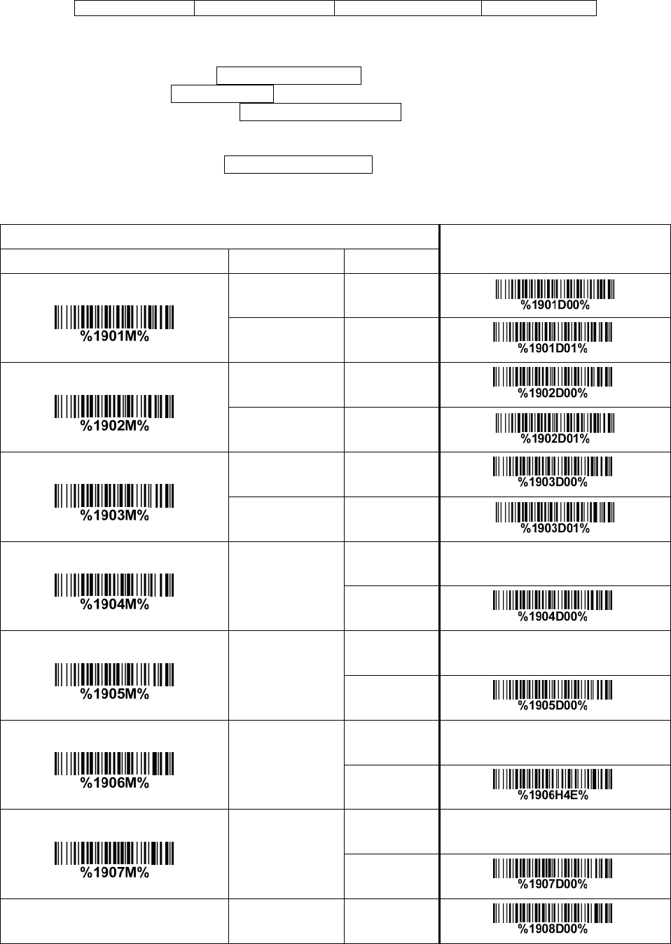
3-8 USB interface for cradle
USB device type:
HID keyboard– By setting, the scanner is used as a USB HID keyboard emulation device. The
keyboard layout setting follows the setting of keyboard layout in 3-6 Keyboard wedge for cradle.
USB virtual COM– By setting, the scanner emulate a regular RS232-based COM port. If a Microsoft
Windows PC is connected to the scanner, a driver is required to install on the connected PC. The
driver will use the next available COM Port number. The driver and the installation guide can be
found in the associated CD and on the manufacturer’s website. A Windows-based software
COM_Text is recommended to display the barcode data in text format. COM_Text emulates some
kind of serial-key typing.
Note: When changing USB Device Type, the scanner automatically restarts.
Simple COM Port Emulation- Please contact the manufacturer for the instruction.
Keyboard layout: The scanner supports different national keyboard layouts.
Inter-character delay: This delay is inserted after each data character transmitted. By selecting, the
user can change the output speed of the scanner to match the speed of the host USB communication
port.
Numeric key:
Alphabetic key- The scanner will output code result as alphabetic key.
Numeric key- The scanner will output code result as pressing numeric keypad ( ‘0’, ‘1’, ‘2’, ‘3’, ‘4’, ‘5’,
‘6’, ‘7’, ‘8’, ‘9’, ‘.’, ‘+’, ‘-‘, ‘/’, ‘*’ only).
Alt + keypad- The scanner will output code result as pressing Alt+ numeric key (on keypad). Note
that the Num Lock control key must be ON. This setting can be specially adapted for use with
different national keyboard layout.
25
Multiple-scan setting
Single-scan setting
Option bar code Option
Alpha.
entry
USB device type
HID keyboard 00* *
HID keyboard for Apple Mac 01
USB virtual COM 02
Simple COM Port Emulation 03
Keyboard layout
USA 00* *
Turkish F 01
Turkish Q 02
French 03
Italian 04
Spanish 05
Slovak 06
Denmark 07
Japanese 08
German 09
Belgian 10
Russian 11
Czech 12
Thailand 13
Hungary 14
Character encoding system
Refer to 3-9 Handheld scan & some global settings.
Inter-character delay 0 ms 00
26
Multiple-scan setting
Single-scan setting
Option bar code Option
Alpha.
entry
5 ms 01* *
10 ms 02
20 ms 03
40 ms 04
60 ms 05
Numeric key
Alphabetic key 00* *
Numeric keypad 01
Alt + keypad 02

27
3-9 Handheld scan & some global settings
Scanning mode:
Good-read off-The trigger button must be pressed once to activate scanning. The scanner will stop
scanning when there is a successful reading or no code is decoded after the Stand-by duration
elapsed.
Momentary-The trigger button acts as a switch. Press button to activate scanning and release
button to stop scanning. The scanner will stop scanning when there is a successful reading or no
code is decoded after the Stand-by duration elapsed.
Alternate continue-The trigger button acts as a toggle switch. Press button to activate or stop
scanning.
Continue-The scanner always keeps scanning, and it does not matter when the trigger button is
pressed or duration is elapsed.
Timeout off-The trigger button must be pressed once to activate scanning. The scanner will stop
scanning when no code is successful decoded after the Stand-by duration elapsed.
Auto-detection- Good-read off – By setting Enable, the scanner will start operating if any nearby
object has been detected. The scanner will stop scanning when there is a successful reading or no
code is decoded after the Stand-by duration elapsed. Once the scanner stops scanning, the present
object must be removed to enable Auto-detection.
Auto-detection- Good-read on – By setting Enable, the scanner will start operating if any nearby
object has been detected. The scanner stops scanning when no code is successful decoded after the
Stand-by duration elapsed. Once the scanner stops scanning, the present object must be removed to
enable Auto-detection.
Auto-detection sensitivity: It is the sensitivity of scanner to ambient brightness change. Sensitivity is
expressed as a percentage value of ambient light change, in the range of 5% to 50%. The smaller the
percentage value, the higher the sensitivity, the easier the scanner will be triggered
Same barcode delay time: If a barcode has been scanned and output once successfully, the scan
operation should be interrupted for delay time or the focus of the scanner must be moved away from the
barcode beyond delay time to active scanning the same barcode. When this feature is set to be “0xFF”,
then the delay time is indefinite.
Double confirm: If it is enabled, the scanner will require a several times of same-decoded-data to
confirm a valid reading.
Global Max./Min. code length for 1D symbol: These two lengths are defined as the valid range of
decoded 1D barcode data length. Make sure that the minimum length setting is no greater than the
maximum length setting, or otherwise the labels of the symbol will not be readable. In particular, the
same value can be set for both minimum and maximum reading length to force the fixed length barcode
decoded.
Same barcode delay time for 2D symbol: If a 2D barcode has been scanned and output once
successfully, the scanner must output the same barcode data beyond delay time. When this feature is
set to be “0xFF”, then the delay time is indefinite.
Notes:
1. Please set the max./min. length for individual barcode in later sections, if special demand is
requested.
2. The number of check digits is included in max./min. code length.
3. These two settings have no effect on the symbols with fixed-length, e.g. UPC-A, UPC-E, EAN-13,
EAN-8 and China Post.
Global G1-G6 string selection: The scanner offer one or two string group for ALL symbols. By setting
one or two digits to indicate which string group you want to apply. You may refer to 3-41 G1-G6 & C1-C2
& FN1 substitution string setting and 3-42 G1-G4 string position & Code ID position.
Example: Group 1 → set 01 or 10. Group 2 and 4 → set 24 or 42.
All valid settings include 00, 01, 02, 03, 04, 05, 06, 10, 11, 12, 13, 14, 15, 16, 20, 21, 22, 23, 24, 25, 26,
30, 31, 32, 33, 34, 35, 36, 40, 41, 42, 43, 44, 45, 46, 50, 51, 52, 53, 54, 55, 56, 60, 61, 62, 63, 64, 65 and
66.
Element amendment: If it is enabled, the scanner can read the barcode comprised with bars and
spaces in different scale.
Character output restraint:
Printable character only- If this option is selected, the scanner will output the printable characters
only, i.e. in ASCII from 20H to 7EH.
Alphanumeric character only- If this option is selected, the scanner will output the alphanumeric
characters only, i.e. “A”-“Z”, “a”-“z”, “0”-“9”.

28
Decoder optimization: If it is enabled, the scanner will optimize the decoder with error correction. This
function is not effective for all types of barcodes.
Data output delay in continue-scan mode: If it is enabled, in the continue-scan mode, the scanner can
store the data while continue-scanning. The scanner will output the data after the predefined delay
elapsed. The maximum storage of data is 1000 characters. If this parameter is set to be “00”, the
scanner will not store data. And if the parameter is set to be “FF”, the scanner will output data after
stopping scanning.
Character encoding system: A character encoding system consists of a code that pairs each character
from a given repertoire. Common examples include Morse code, the Baudot code, the ASCII and
Unicode. If the data received does not display with the proper characters (e.g. domestic language), it
maybe because the barcode being scanned was created using a character encoding system that is
different from the one the host program is expecting. Try alternate options to find the proper one.
Complete data output before next decode attempt: This setting is active only when USB device type
is set as “HID keyboard” or “HID keyboard for Apple Mac”, refer to 3-8 USB interface for cradle. If it is
enabled, the imager will not start next decode attempt until previous data output is completed.
29
Multiple-scan setting
Single-scan setting
Option barcode
Option
Alpha. entry
Scan mode
Good-read off 00
Momentary 01* *
Alternate continue 02
Continue 03
Good-read on 04
Auto-detection- Good-read on 06
Auto-detection- Good-read off 07
Auto-detection sensitivity
5%* 00* *
10% 01
15% 02
20% 03
25% 04
30% 05
35% 06
40% 07
45% 08
50% 09
Standby duration
4 seconds 00* *
8 seconds 01
16 seconds 02
24 seconds 03
30 seconds 04
30
Multiple-scan setting
Single-scan setting
Option barcode
Option
Alpha. entry
1 minute 05
1.5 minutes 06
2 minutes 07
5 minutes 08
7 minutes 09
10 minutes 10
15 minutes 11
20 minutes 12
30 minutes 13
45 minutes 14
1 hour 15
Same barcode delay time for
1D symbol
00-FF16 (50 ms)
00-FF16
00
08* *
Same barcode delay time for
2D symbol
00-FF16 (50 ms)
00-FF16
00
08* *
Double confirm
00-09 (00: none )
00-09
00* *
Global max. code length for
1D symbol
04-99
04-99
99* *
Global min. code length for
1D symbol 01-99 01-99
31
Multiple-scan setting
Single-scan setting
Option barcode
Option
Alpha. entry
04* *
Global G1-G6 string selection
00-66
(00: none )
00-66
00* *
Element amendment
Disable 00
Enable 01* *
Character output restraint
None 00* *
Printable character only 01
Alphanumeric character only 02
Decoder optimization
Disable 00
Enable 01* *
Data output delay in
continue-scan mode
00-99 (100 ms)
FF (Never)
00-FF16
00* *
Character encoding system
ASCII 00* *
UTF-8 01
Windows-1251 02
Complete data output before
next decode attempt
Disable 00* *
Enable 01
32
3-10 Indication for handheld unit
Power on alert: After power-on the scanner will generate an alert signal to indicate a successful
self-test.
LED indication: After each successful reading, the LED above the scanner will light up to indicate a
good barcode reading.
Beeper indication: After each successful reading, the scanner will beep to indicate a good barcode
reading, and its beep tone duration is adjustable.
Beep tone duration: This parameter can be adjusted for a good reading upon favorite usage.
Volume of beeper: This parameter can be adjusted for different level of the volume of the beeper.
Vibrator indication: After each successful reading, the vibrator will vibrate to indicate a good barcode
reading.
Multiple-scan setting
Single-scan setting
Option bar code
Option
Alpha. entry
Power on alert
Disable 00
Enable 01* *
LED indication
Disable 00
Enable 01* *
Beeper indication
Disable 00
Enable 01*
Beep tone duration
01-09 (10 ms )
01-09
05* *
Volume of beeper
Low 00
Middle 01
High 02* *
Vibrator indication
Disable 00
Enable 01* *
33
3-11 Decode illumination and decode aiming pattern
Decode illumination mode: Enable illumination causes the scanner to turn on the illumination to aid
decoding. Disable illumination to turn off illumination for the scanner during decoding. Better quality
images could be obtained with illumination support. The effectiveness of the illumination decreases as
the distance to the target increases.
Decode aiming pattern: When this option is enabled, the scanner will project the aiming pattern during
the code capture.
Level of decode illumination: This parameter can be adjusted for different level of decode illumination.
Illumination mode of Auto-detection:
Always off- Illumination LED will be always turned off.
Enable illumination in low light conditions- In low light conditions, the scanner will turn on
illumination LED automatically to ensure normal work. While in other light conditions, the illumination
LED will be turned off automatically.
Always on- Illumination LED will be always turned on (Default).
Note: This function is only valid in Auto-detection mode.
34
Multiple-scan setting Single-scan setting
Option bar code Option Alpha. Entry
Decode illumination
Always Off 00
Flashing 02* *
On when reading 03
Decode aiming pattern
Always Off 00
Always On 01
On before reading 02
On when reading 03* *
Level of decode illumination
Disable decode
illumination 00
Low 01
Middle 02* *
High 03
Illumination mode of
Auto-detection
Always off 00
Enable illumination in
low light conditions 01* *
Always on 02
35
3-12 Single type of barcode read
1D symbols read: A global setting of 1D symbols readability.
2D symbols read: A global setting of 2D symbols readability.
Multiple-scan setting Single-scan setting
Option barcode Option Alpha. entry
1D symbols read
Follow respective 1D
symbol setting 00* *
All 1D Disable 01
All 1D Enable 02
2D symbols read
Follow respective 2D
symbol setting 00* *
All 2D Disable 01
All 2D Enable 02
Only PDF417 Enable 03
Only QR code Enable 04
Only Data Matrix Enable 05
Only MaxiCode Enable 06
Only Aztec Code Enable 07
Only Han Xin Code Enable 08
36
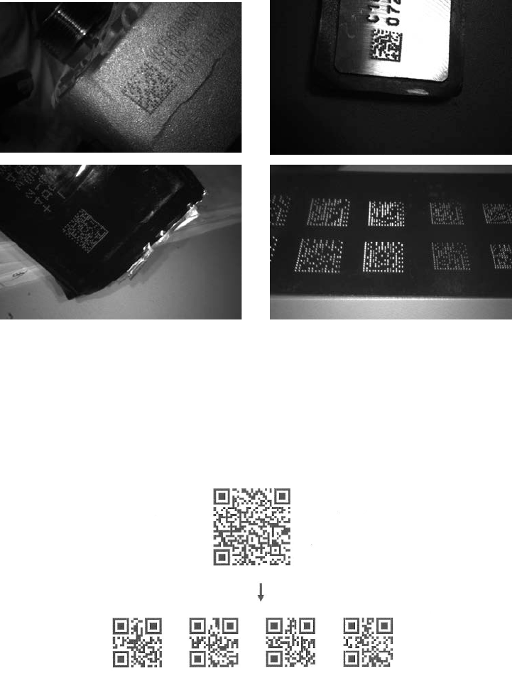
3-13 DPM, Multiple symbols, Structured append read, etc.
DPM format read: By setting Enable, the scanner can read 2D symbols in DPM (Direct Park Marking)
format. Some barcodes in DPM format are shown below.
Multiple symbols & structured append symbols read:
1) By setting Enable, the scanner allows to read multiple symbols with a single pull of the scanner's
trigger. If the user pulls and holds the trigger, aiming the scanner at a series of symbols, it reads unique
symbols once, beeping for each success read. The scanner attempts to find and decode new symbols
as long as the trigger is pulled.
2) By setting Enable, the scanner will output data only when all Structured Append symbols have been
decoded. The lower part of below figure shows an example of four Structured Append symbols, with
the same data as that in the upper symbol.
3) By setting Disable, the scanner will only read the symbol closest to the aiming beam.
Single symbol (above) and Structured Append series of symbols (below) encoding
“ABCDEFGHIJKMNOPQRSTUVWXYZ0123456789ABCDEFGHIJKLMNOPQRSTUVWXYZ”
Mobile screen read: By setting enable, the scanner can read barcodes on a mobile screen better.
However, this will slow the reading speed of normal barcodes a little bit, and the decode illumination will
flash.
37
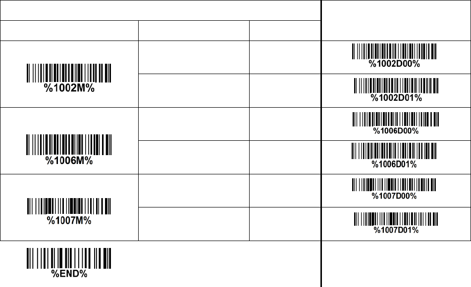
Multiple-scan setting Single-scan setting
Option bar code Option Alpha. entry
DPM format read
Disable 00* *
Enable 01
structured append
symbols read
Disable 00*
Enable 01 *
Mobile screen read
Disable 00* *
Enable 01

38
3-14 UPC-A
Read:
Format
System character
Data digits (10 digits)
Check digit
Check digit verification: The check digit is optional.
Check digit trans.: By setting Enable, check digit will be transmitted.
Code ID setting: Code ID is a one-or-two-character string used to represent the symbol upon a
succeeding reading. If you want application to transmit Code ID, you must set Code ID transmission to
be enabled, refer to 3-43 String transmission.
Insertion group selection: Refer to Global insertion group selection of 3-9 Handheld scan & some
global settings.
Supplement digits: The Supplement digits barcode is the supplemental 2 or 5 characters.
Format
System character
Data digits (10 digits)
Check digit
Supplement digits 2 or 5
Truncation/Expansion:
Truncate leading zeros- The leading “0” digits of UPC-A data characters can be truncated when the
feature is enabled.
Expand to EAN-13- It extends to 13-digits with a “0” leading digit when the feature is enabled.
Truncate system character- The system character of UPC-A data can be truncated when the feature
is enabled.
Add country code- The country code (“0” for USA) can be added when the feature is enabled.
39
Multiple-scan setting Single-scan setting
Option barcode Option Alpha. entry
Read
Disable 00
Enable 01* *
Check digit verification
Disable 00
Enable 01* *
Check digit trans.
Disable 00
Enable 01* *
Code ID setting
00-FF16 (ASCII)
00-FF16
<A>* *
Insert group selection
00-66
00-66
00*
Supplement digits
None 00* *
2 digits 01
5 digits 02
2 or 5 digits 03
Truncation/Expansion
None 00* *
Truncate leading zeros 01
Expand to EAN-13 02
Truncate system character 03
Add country code 04

40
3-15 UPC-E
Read:
Format
System character “0”
Data digits (6 digits)
Check digit
Check digit verification: The check digit is optional and made as the sum of the numerical value of the
data digits.
Check digit trans.: By setting Enable, check digit will be transmitted.
Code ID setting: Refer to Code ID setting of 3-14 UPC-A.
Insertion group selection: Refer to Insertion group selection of 3-14 UPC-A.
Supplement digits:
Format
System character “0”
Data digits (6 digits)
Check digit
Supplement digits 2 or 5
Truncation/Expansion:
Truncate leading zeros- Refer to Truncation/Expansion of 3-14 UPC-A.
Expand to EAN-13- It extends to 13-digits with “0” digits when the feature is set to be enabled.
Example: Barcode “0123654”,
Output: “0012360000057”.
Expand to UPC-A- It extends to 12-digits when the feature is set to be enabled.
Truncate system character- The system character “0” of UPC-E data can be truncated when the
feature is enabled.
41
Multiple-scan setting
Single-scan setting
Option barcode
Option
Alpha. entry
Read
Disable 00
Enable 01* *
Check digit verification
Disable 00
Enable 01* *
Check digit trans.
Disable 00
Enable 01* *
Code ID setting
00-FF16 (ASCII)
00-FF16
<D>*
*
Insert group selection
00-66
00-66
00* *
Supplement digits
None 00* *
2 digits 01
5 digits 02
2 or 5 digits 03
Truncation/Expansion
None 00* *
Truncate leading zeros 01
Expand to EAN-13 02
Expand to UPC-A 03
Truncate system character 04

42
3-16 UPC-E1
Read:
Format
System character “1”
Data digits (5 digits)
Check digit
Check digit verification: The check digit is optional and made as the sum of the numerical value of the
data digits.
Check digit trans.: By setting Enable, check digit will be transmitted.
Code ID setting: Refer to Code ID setting of 3-14 UPC-A.
Insertion group selection: Refer to Insertion group selection of 3-14 UPC-A.
Supplement digits:
Format
System character “1”
Data digits (5 digits)
Check digit
Supplement digits 2 or 5
Truncation/Expansion:
Expand to EAN-13- It extends to 13-digits with “0” digits when the feature is set to be enabled.
Expand to UPC-A- It extends to 12-digits when the feature is set to be enabled.
Truncate system character- The system character “1” of UPC-E1 data can be truncated when the
feature is enabled.
43
Multiple-scan setting Single-scan setting
Option barcode
Option
Alpha. entry
Read
Disable 00
Enable 01* *
Check digit verification
Disable 00
Enable 01* *
Check digit trans.
Disable 00
Enable 01* *
Code ID setting
00-FF16 (ASCII)
00-FF16
<D>* *
Insert group selection
00-66
00-66
00* *
Supplement digits
None 00* *
2 digits 01
5 digits 02
2 or 5 digits 03
Truncation/Expansion
None 00* *
Expand to EAN-13 02
Expand to UPC-A 03
Truncate system character 04

44
3-17 EAN-13 (ISBN/ISSN)
Read:
Format
Data digits (12 digits)
Check digit
Check digit verification: The check digit is optional and made as the sum of the numerical value of the
data digits.
Check digit transmission: By setting Enable, check digit will be transmitted.
EAN-13 code ID setting: Refer to Code ID setting of 3-14 UPC-A.
Insertion group selection: Refer to Insertion group selection of 3-14 UPC-A.
Supplement digits:
Format
Data digits (12 digits)
Check digit
Supplement digits 2 or 5
ISBN/ISSN conversion: The ISBN (International Standard Book Number, or Bookland EAN) and ISSN
(International Standard Serial Number) are two kinds of barcode for books and magazines. The ISBN is
10 digits with leading “978” and the ISSN is 8 digits with leading “977” of the EAN-13 symbol.
Example:
Barcode “9780194315104”, Output: “019431510X”.
Barcode “9771005180004”, Output: “10051805”.
ISBN/ISSN code ID setting: Refer to Code ID setting of 3-14 UPC-A.
45
Multiple-scan setting
Single-scan setting
Option barcode
Option
Alpha. entry
Read
Disable 00
Enable 01* *
Check digit verification
Disable 00
Enable 01* *
Check digit transmission
Disable 00
Enable 01* *
EAN-13 code ID setting
00-FF16
(ASCII)
00-FF16
<A>* *
Insert group selection
00-66
00-66
00* *
Supplement digits
None 00* *
2 digits 01
5 digits 02
2 or 5 digits 03
ISBN/ISSN conversion
Disable 00* *
Enable 01
ISBN/ISSN code ID setting
00-FF16
(ASCII)
00-FF16
<B>* *

46
3-18 EAN-8
Read:
Format
Data digits (7 digits)
Check digit
Check digit verification: The check digit is optional and made as the sum of the numerical value of the
data digits.
Check digit trans.: By setting Enable, check digit will be transmitted.
Code ID setting: Refer to Code ID setting of 3-14 UPC-A.
Insertion group selection: Refer to Insertion group selection of 3-14 UPC-A.
Supplement digits:
Format
Data digits (7 digits)
Check digit
Supplement Digits 2 or 5
Truncation/Expansion: Refer to Truncation/Expansion of 3-14 UPC-A.
47
Multiple-scan setting
Single-scan setting
Option barcode
Option
Alpha. entry
Read
Disable 00
Enable 01* *
Check digit verification
Disable 00
Enable 01* *
Check digit trans.
Disable 00
Enable 01* *
Code ID setting
00-FF16
(ASCII)
00-FF16
<C>* *
Insert group selection
00-66
00-66
00* *
Supplement digits
None 00* *
2 digits 01
5 digits 02
2 or 5 digits 03
Truncation/Expansion
None 00* *
Truncate leading zero 01
Expand to EAN-13 02

48
3-19 Code 39 (Code 32, Trioptic Code 39)
Read:
Format
*
Data digits (variable)
Check digit (optional)
*
Check digit verification: The check digit is optional and made as the sum module 43 of the numerical
value of the data digits.
Check digit transmission: By setting Enable, check digit will be transmitted.
Max./Min. code length: Each symbol has own max./min. code length. If both setting of max./min. code
length are “00”s, the setting of global max./min. code length is effective. The length is defined as to the
actual barcode data length to be sent. Label with length exceeds these limits will be rejected. Make
sure that the minimum length setting is no greater than the maximum length setting, or otherwise all the
labels of the symbol will not be readable. In particular, you can see the same value for both minimum
and maximum reading length to force the fixed length barcode decoded.
Code ID setting: Refer to Code ID setting of 3-14 UPC-A.
Insertion group selection: Refer to Insertion group selection of 3-14 UPC-A.
Start/End transmission: The start and end characters of Code 39 are “*”s. You can transmit all data
digits including two “*”s.
“*” as data character: By setting Enable, “*” can be recognized as data character.
Convert Code 39 to Code 32: Code 32 is a variant of Code 39 used by the Italian pharmaceutical
industry. Note that Code 39 must be enabled in order for this parameter to function.
Format of Code 32
“A” (optional)
Data digits (8 digits)
Check digit
Code 32 Prefix “A” transmission: By setting Enable, the prefix character “A” can be added to all Code
32 barcodes.
Trioptic Code 39 read: Trioptic Code 39 is a variant of Code 39 used in the marking of magnetic tapes
and computer cartridges. Trioptic Code 39 symbols always contain six characters.
Format
$
Data digits (6 digits)
$
Trioptic Code 39 Start/End transmission: The start and end characters of Trioptic Code 39 are “$”
s. You can transmit all data digits including two “$”s.
49
Multiple-scan setting
Single-scan setting
Option bar code
Option
Alpha. entry
Read
Disable 00
Enable 01* *
Check digit verification
Disable 00* *
Enable 01
Check digit transmission
Disable 00* *
Enable 01
Max. code length
00-99
00-99
00* *
Min. code length
00-99
00-99
01* *
Code ID setting
00-FF16
(ASCII)
00-FF16
<M>* *
Insert group selection
00-66
00-66
00* *
Format
Standard 00* *
Full ASCII 01
Start/End transmission
Disable 00* *
Enable 01
“*” as data character
Disable 00* *
Enable 01
Convert Code 39 to Code 32
Disable 00* *
Enable 01
50
Multiple-scan setting
Single-scan setting
Option bar code
Option
Alpha. entry
Code 32 Prefix “A” transmission
Disable 00* *
Enable 01
Trioptic Code 39 read
Disable 00* *
Enable 01
Trioptic Code 39 Start/End
transmission
Disable 00* *
Enable 01

51
3-20 Interleaved 2 of 5
Read:
Format
Data digits (Variable)
Check digit (optional)
Check digit verification: The check digit is made as the sum module 10 of the numerical values of all
data digits. There are two optional check digit algorithms: the specified Uniform Symbol Specification
(USS) and the Optical Product Code Council (OPCC).
Check digit transmission: By setting Enable, check digit will be transmitted.
Max./Min. code length: Refer to Max./Min. code length of 3-19 Code 39.
Code ID setting: Refer to Code ID setting of 3-14 UPC-A.
Insertion group selection: Refer to Insertion group selection of 3-14 UPC-A.
52
Multiple-scan setting
Single-scan setting
Option bar code
Option
Alpha. entry
Read
Disable 00
Enable 01* *
Check digit verification
Disable 00* *
USS 01
OPCC 02
Check digit transmission
Disable 00* *
Enable 01
Max. code length
00-99
00-99
00* *
Min. code length
00-99
00-99
06* *
Code ID setting
00-FF16
(ASCII)
00-FF16
<I>* *
Insert group selection
00-66
00-66
00* *
53
3-21 Industrial 2 of 5
Read:
Format
Data digits (variable)
Max./Min. code length: Refer to Max./Min. code length of 3-19 Code 39.
Code ID setting: Refer to Code ID setting of 3-14 UPC-A.
Insertion group selection: Refer to Insertion group selection of 3-14 UPC-A.
Multiple-scan setting
Single-scan setting
Option bar code
Option
Alpha. entry
Read
Disable 00* *
Enable 01
Max. code length
00-99
00-99
00* *
Min. code length
00-99
00-99
00* *
Code ID setting
00-FF16
(ASCII)
00-FF16
<H>* *
Insert group selection
00-66
00-66
00* *
54
3-22 Matrix 2 of 5
Read:
Format
Data digits (variable)
Check digit (optional)
Check digit verification: The check digit is made as the sum module 10 of the numerical values of all
data digits.
Check digit transmission: By setting Enable, check digit will be transmitted.
Max./Min. code length: Refer to Max./Min. code length of 3-19 Code 39.
Code ID setting: Refer to Code ID setting of 3-14 UPC-A.
Insertion group selection: Refer to Insertion group selection of 3-14 UPC-A.
Multiple-scan setting
Single-scan setting
Option bar code
Option
Alpha. entry
Read
Disable 00
Enable 01* *
Check digit verification
Disable 00* *
Enable 01
Check digit transmission
Disable 00* *
Enable 01
Max. code length
00-99
00-99
00* *
Min. code length
00-99
00-99
06* *
Code ID setting
00-FF16
(ASCII)
00-FF16
<X>* *
Insert group selection
00-66
00-66
00* *
55
3-23 Codabar
Read:
Format
Start character
Data digits (variable)
Check digit (optional)
End character
Check digit verification: The check digit is made as the sum module 16 of the numerical values of all
data digits.
Check digit transmission: By setting Enable, check digit will be transmitted.
Max./Min. code length: Refer to Max./Min. code length of 3-19 Code 39.
Code ID setting: Refer to Code ID setting of 3-14 UPC-A.
Insertion group selection: Refer to Insertion group selection of 3-14 UPC-A.
Start/End type: Codabar has four pairs of Start/End pattern; you may select one pair to match your
application.
Start/End transmission: Refer to Start/End transmission of 3-19 Code 39.
Start/End character equality: By setting Enable, the start and end character of a Codabar barcode
must be the same.
Multiple-scan setting Single-scan setting
Option bar code Option Alpha. entry
Read
Disable 00
Enable 01* *
Check digit verification
Disable 00* *
Enable 01
Check digit transmission
Disable 00* *
Enable 01
Max. code length
00-99
00-99
00* *
Min. code length
00-99
00-99
00* *
Code ID setting
00-FF16
(ASCII)
00-FF16
<N>* *
Insert group selection
00-66
00-66
00* *
Start/End type ABCD/ABCD 00* *
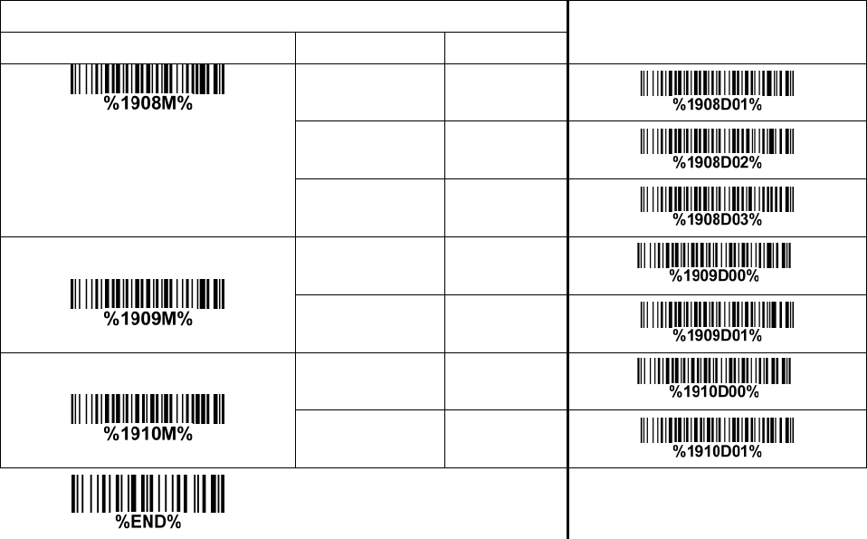
56
Multiple-scan setting Single-scan setting
Option bar code Option Alpha. entry
abcd/abcd 01
ABCD/TN*E 02
abcd/tn*e 03
Start/End transmission
Disable 00* *
Enable 01
Start/End character equality
Disable 00* *
Enable 01

57
3-24 Code 128
Read:
Format
Data digits (variable)
Check digit (optional)
Check digit verification: The check digit is made as the sum module 103 of all data digits.
Check digit transmission: By setting Enable, check digit will be transmitted.
Max./Min. code length: Refer to Max./Min. code length of 3-19 Code 39.
Code ID setting: Refer to Code ID setting of 3-14 UPC-A.
Insertion group selection: Refer to Insertion group selection of 3-14 UPC-A.
Truncate leading zeros: The leading “0” digits of Code 128 barcode characters can be truncated when
the feature is enabled.
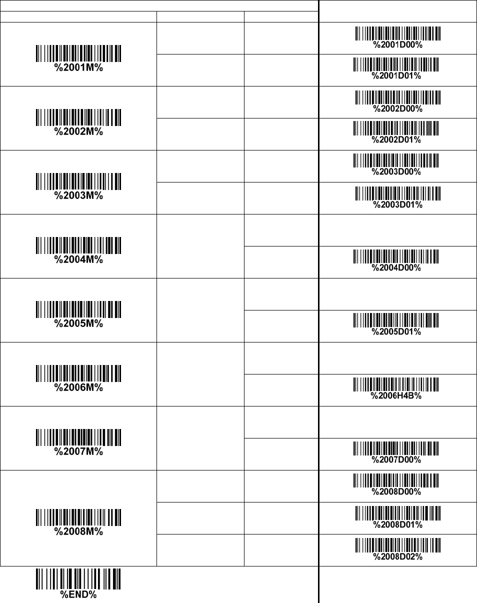
58
Multiple-scan setting
Single-scan setting
Option bar code
Option
Alpha. entry
Read
Disable 00
Enable 01* *
Check digit verification
Disable 00
Enable 01* *
Check digit transmission
Disable 00* *
Reserved 01
Max. code length
00-99
00-99
00* *
Min. code length
00-99
00-99
01* *
Code ID setting
00-FF16
(ASCII)
00-FF16
<K>* *
Insert group selection
00-66
00-66
00* *
Truncate leading zeros
Disable 00* *
All leading “0”s 01
Only the first “0” 02

59
3-25 UCC/EAN 128
Read:
Format
Data digits (variable)
Check digit (optional)
Check digit verification: The check digit is made as the sum module 103 of all data digits.
Check digit transmission: By setting Enable, check digit will be transmitted.
Max. /Min. code length: Refer to Max./Min. code length of 3-19 Code 39.
Code ID setting: Refer to Code ID setting of 3-14 UPC-A.
Insertion group selection: Refer to Insertion group selection of 3-14 UPC-A.
Truncate leading zeros: Refer to Truncate leading zeros of 3-24 Code 128.
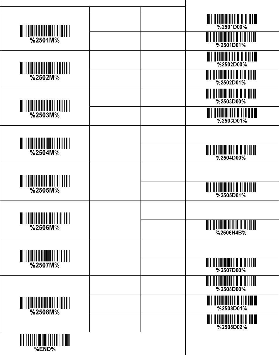
60
Multiple-scan setting
Single-scan setting
Option bar code
Option
Alpha. entry
Read
Disable 00
Enable 01*
*
Check digit verification
Disable 00
Enable 01* *
Check digit transmission
Disable 00*
*
Reserved 01
Max. code length
00-99
00-99
00*
*
Min. code length
00-99
00-99
01*
*
Code ID setting
00-FF16
(ASCII)
00-FF16
<K>*
*
Insert group selection
00-66
00-66
00*
*
Truncate leading zeros
Disable 00*
*
All leading “0”s 01
Only the first “0” 02
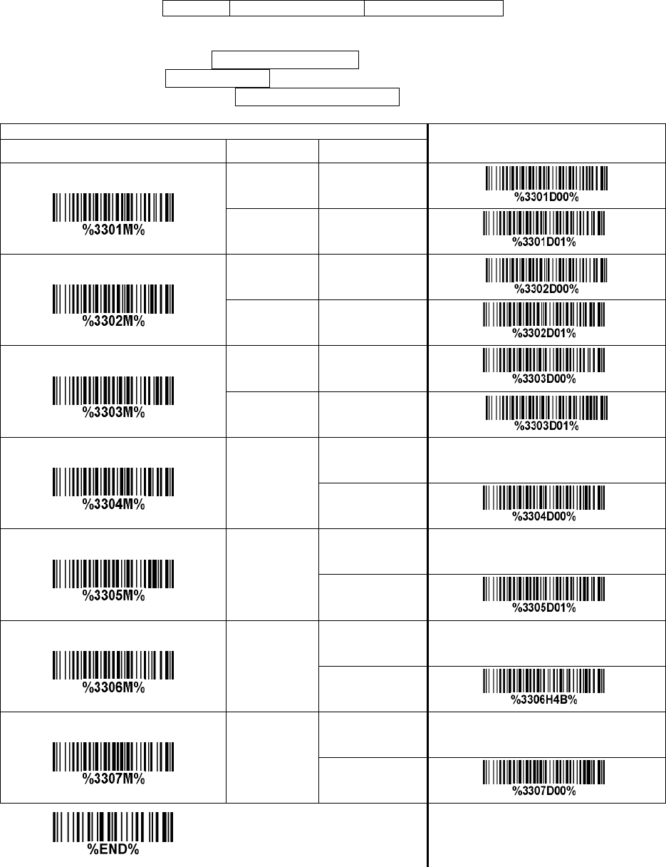
61
3-26 ISBT 128
Read:
Format
“=” or “&”
Data digits (variable)
Check digit (optional)
Check digit verification: The check digit is made as the sum module 103 of all data digits.
Check digit transmission: By setting Enable, check digit will be transmitted.
Max./Min. code length: Refer to Max./Min. code length of 3-19 Code 39.
Code ID setting: Refer to Code ID setting of 3-14 UPC-A.
Insertion group selection: Refer to Insertion group selection of 3-14 UPC-A.
Multiple-scan setting
Single-scan setting
Option bar code Option Alpha. entry
Read
Disable 00
Enable 01* *
Check digit verification
Disable 00
Enable 01* *
Check digit transmission
Disable 00* *
Reserved 01
Max. code length
00-99
00-99
00* *
Min. code length
00-99
00-99
01*
*
Code ID setting
00-FF16
(ASCII)
00-FF16
<K>* *
Insert group selection
00-66
00-66
00* *
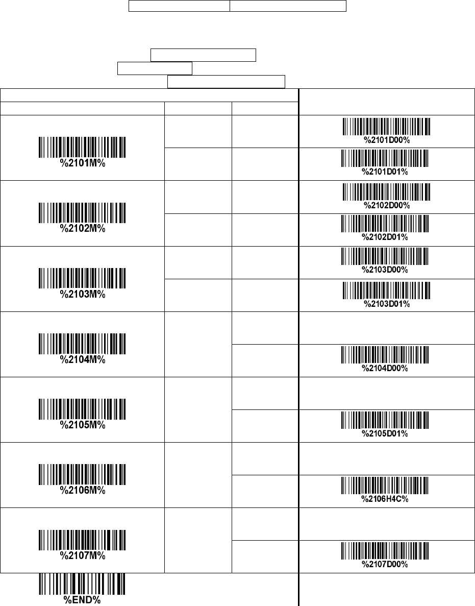
62
3-27 Code 93
Read:
Format
Data digits (variable)
2 check digits (optional)
Check digit verification: The check digit is made as the sum module 47 of the numerical values of all
data digits.
Check digit transmission: By setting Enable, check digit will be transmitted.
Max./Min. code length: Refer to Max./Min. code length of 3-19 Code 39.
Code ID setting: Refer to Code ID setting of 3-14 UPC-A.
Insertion group selection: Refer to Insertion group selection of 3-14 UPC-A.
Multiple-scan setting
Single-scan setting
Option bar code
Option
Alpha. entry
Read
Disable 00
Enable 01*
*
Check digit verification
Disable 00
Enable 01*
*
Check digit transmission
Disable 00*
*
Enable 01
Max. code length
00-99
00-99
00* *
Min. code length
00-99
00-99
01* *
Code ID setting
00-FF16
(ASCII)
00-FF16
<L>* *
Insert group selection
00-66
00-66
00* *

63
3-28 Code 11
Read:
Format
Data digits (variable)
Check digit 1 (optional )
Check digit 2 (optional)
Check digit verification: The check digit is presented as the sum module 11 of all data digits.
Check digit transmission: By setting Enable, check digit 1 and check digit 2 will be transmitted upon
your selected check digit verification method.
Max./Min. code length: Refer to Max./Min. code length of 3-19 Code 39.
Code ID setting: Refer to Code ID setting of 3-14 UPC-A.
Insertion group selection: Refer to Insertion group selection of 3-14 UPC-A.
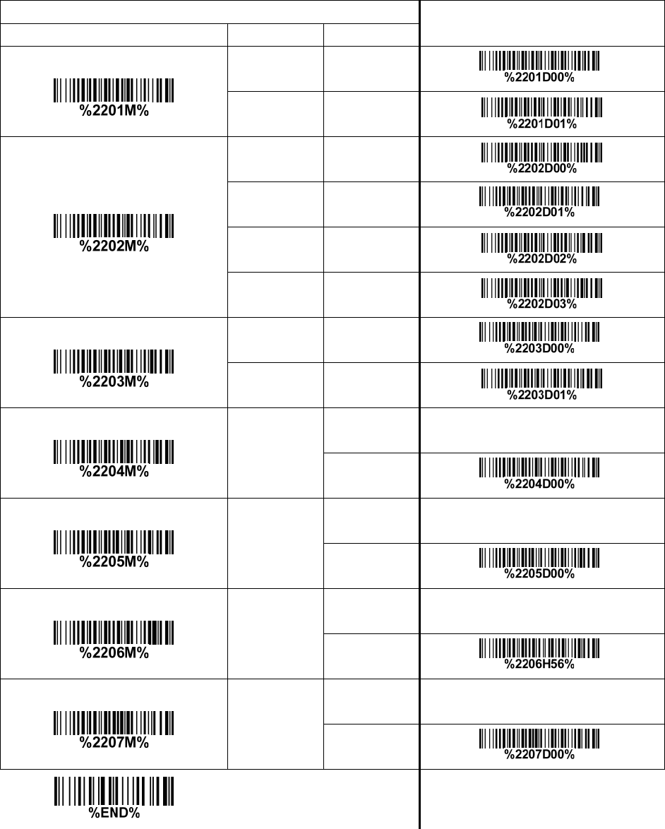
64
Multiple-scan setting Single-scan setting
Option bar code Option Alpha. entry
Read
Disable 00* *
Enable 01
Check digit verification
Disable 00
One digit 01* *
Reserved 02
Reserved 03
Check digit transmission
Disable 00* *
Enable 01
Max. code length
00-99
00-99
00* *
Min. code length
00-99
00-99
00* *
Code ID setting
00-FF16
(ASCII)
00-FF16
<V>* *
Insert group selection
00-66
00-66
00* *

65
3-29 MSI/Plessey
Read:
Format
Data digits (variable)
Check digit 1 (optional)
Check digit 2 (optional)
Check digit verification: The MSI/Plessey has one or two optional check digits. There are three
methods of verifying check digits, i.e. Mod10, Mod10/10 and Mod 11/10. The check digit 1 and check
digit 2 will be calculated as the sum module 10 or 11 of the data digits.
Check digit transmission: By setting Enable, check digit 1 and check digit 2 will be transmitted upon
your selected check digit verification method.
Max./Min. code length: Refer to Max./Min. code length of 3-19 Code 39.
Code ID setting: Refer to Code ID setting of 3-14 UPC-A.
Insertion group selection: Refer to Insertion group selection of 3-14 UPC-A.
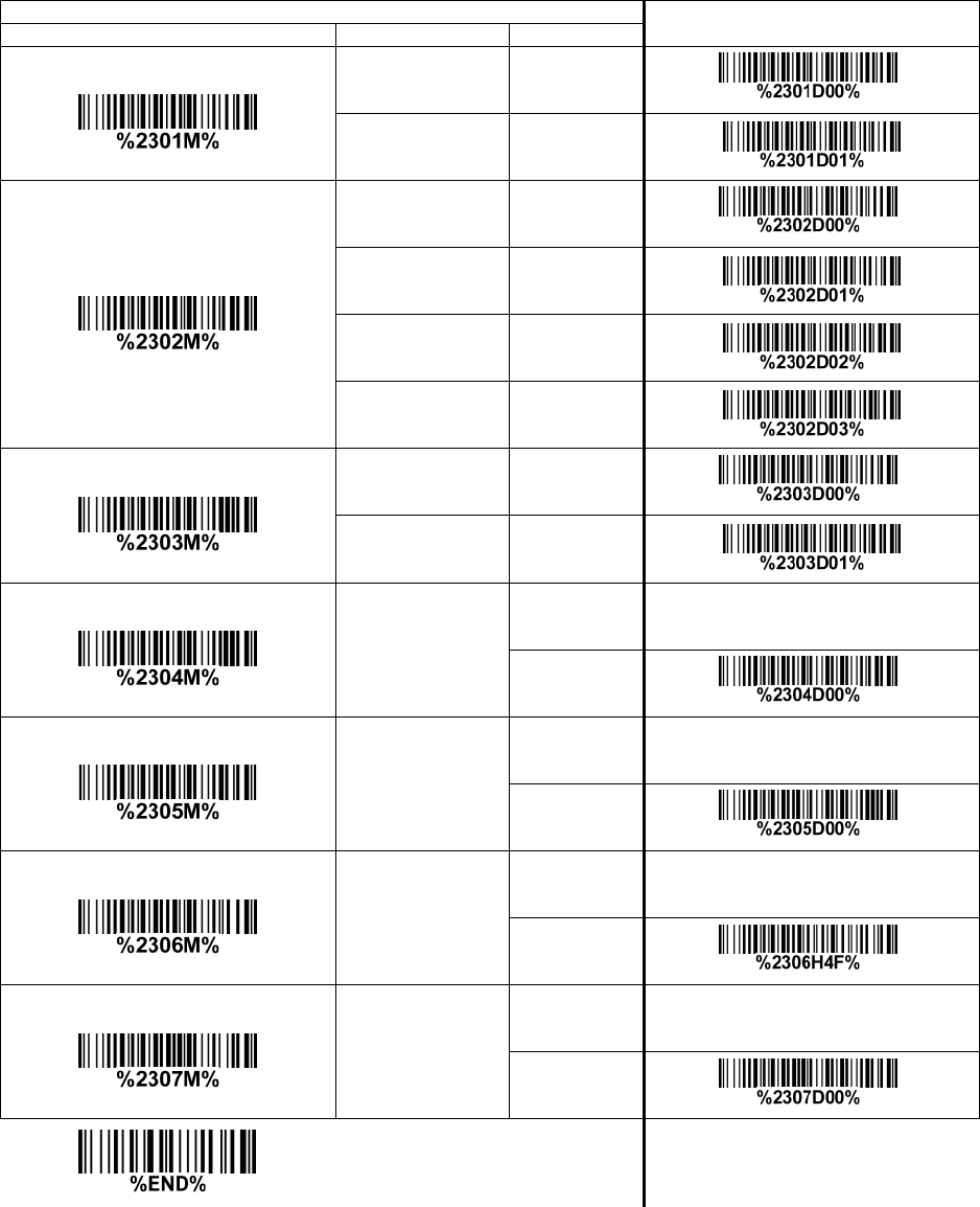
66
Multiple-scan setting
Single-scan setting
Option bar code
Option
Alpha. entry
Read
Disable 00* *
Enable 01
Check digit verification
Disable 00* *
1 digit (mod 10) 01
Reserved 02
Reserved 03
Check digit transmission
Disable 00* *
Enable 01
Max. code length
00-99
00-99
00* *
Min. code length
00-99
00-99
00* *
Code ID setting
00-FF16
(ASCII)
00-FF16
<O>* *
Insert group selection
00-66
00-66
00* *

67
3-30 UK/Plessey
Read:
Format
Data digits (variable)
2 check digits (optional)
Check digit verification: The UK/Plessey has one or two optional check digits. The check digit 1 and
check digit 2 will be calculated as the sum module 10 or 11 of the data digits.
Check digit transmission: By setting Enable, check digit will be transmitted.
Max./Min. code length: Refer to Max./Min. code length of 3-19 Code 39.
Code ID setting: Refer to Code ID setting of 3-14 UPC-A.
Insertion group selection: Refer to Insertion group selection of 3-14 UPC-A.
Multiple-scan setting
Single-scan setting
Option bar code
Option
Alpha. entry
Read
Disable 00* *
Enable 01
Check digit verification
Disable 00
Enable 01* *
Check digit transmission
Disable 00* *
Enable 01
Max. code length
00-99
00-99
00* *
Min. code length
00-99
00-99
01* *
Code ID setting
00-FF16
(ASCII)
00-FF16
<U>* *
Insert group selection
00-66
00-66
00* *
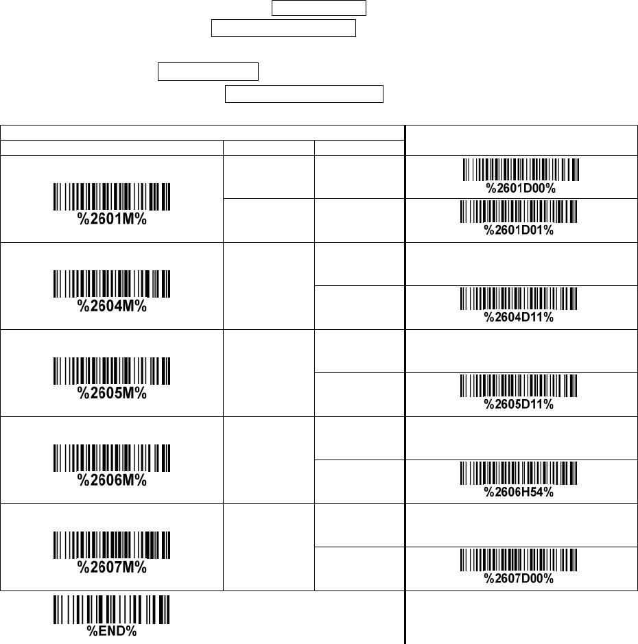
68
3-31 China Post
Read:
Format
11 Data digits
Max. /Min. code length: Refer to Max./Min. code length of 3-19 Code 39. The code length of China
Post is 11.
Code ID setting: Refer to Code ID setting of 3-14 UPC-A.
Insertion group selection: Refer to Insertion group selection of 3-14 UPC-A.
Multiple-scan setting
Single-scan setting
Option bar code
Option
Alpha. entry
Read
Disable 00
Enable 01*
*
Max. code length
00-99
00-99
11*
*
Min. code length
00-99
00-99
11*
*
Code ID setting
00-FF16
(ASCII)
00-FF16
<T>*
*
Insert group selection
00-66
00-66
00*
*
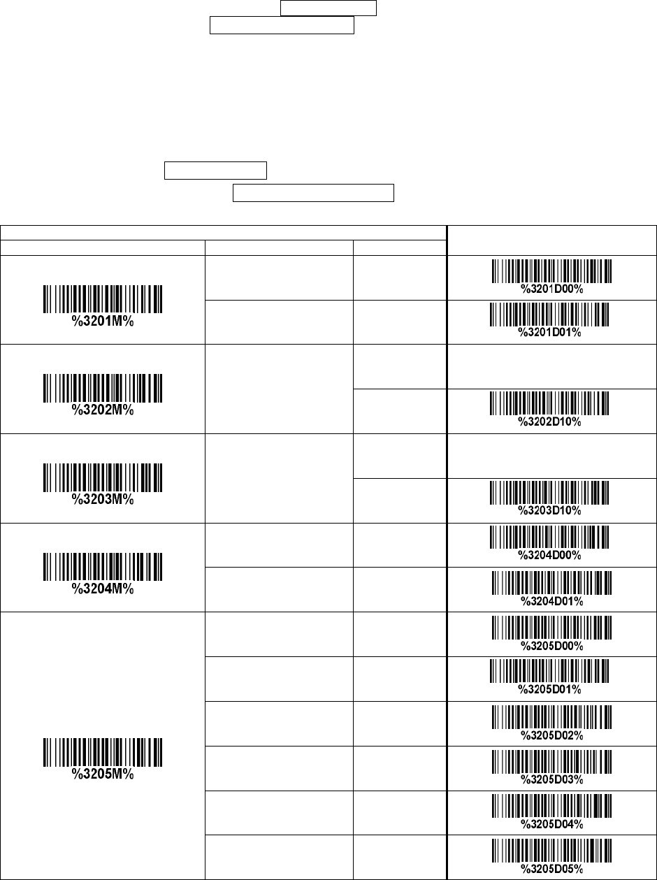
69
3-32 China Finance
Note: This type of barcode is not Omni-directionally decodable. The encodable character set includes
numeric 0 to 9. Among the symbol of 0 to 9, 0 and 2, 4 and 9, 5 and 8, 6 and 7, have the symmetrical
pattern; the pattern of 1 and 3 is symmetrical.
Read:
Format
10 Data digits
Max./Min. code length: Refer to Max./Min. code length of 3-19 Code 39.
Check digit verification: The check digit is made as the sum module 10 of the numerical values of all
data digits.
Leading character 5/6/7/8/9 converted to A/B/C/D/E: By setting, leading character 5/6/7/8/9 can be
converted to A/B/C/D/E.
Leading character assignment: By setting, only the barcode with the assigned leading character can
be output.
Code ID setting: Refer to Code ID setting of 3-14 UPC-A.
Insertion group selection: Refer to Insertion group selection of 3-14 UPC-A.
Multiple-scan setting
Single-scan setting
Option bar code
Option
Alpha. entry
Read
Disable 00
Enable 01* *
Max. code length
00-99
00-99
10* *
Min. code length
00-99
00-99
10*
*
Check digit verification
Disable 00*
*
Reserved 01
Leading character 5/6/7/8/9
converted to A/B/C/D/E
Disable 00
Enable 01* *
Only 5 converted to A 02
Only 6 converted to B 03
Only 7 converted to C 04
Only 8 converted to D 05
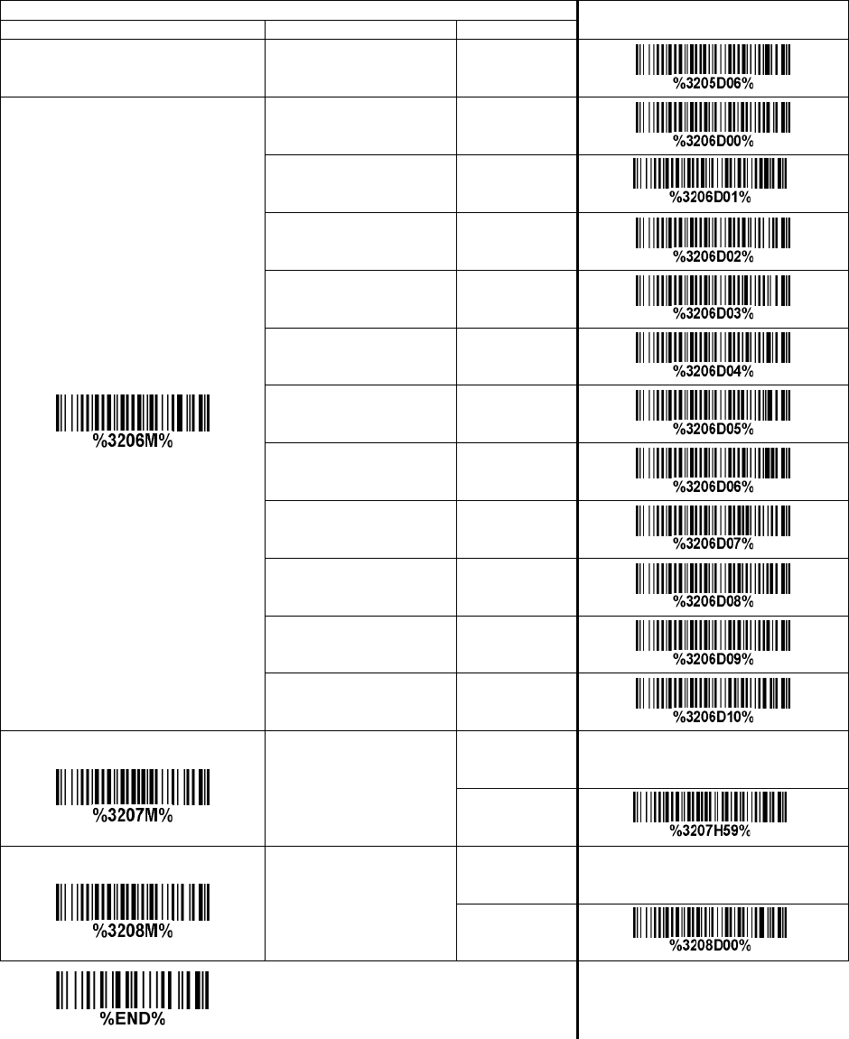
70
Multiple-scan setting
Single-scan setting
Option bar code
Option
Alpha. entry
Only 9 converted to E 06
Leading character assignment
Disable 00
Assigned to 0 01* *
Assigned to 5(A) 02
Assigned to 6(B) 03
Assigned to 7(C) 04
Assigned to 8(D) 05
Assigned to 9(E) 06
Assigned to 1 07
Assigned to 2 08
Assigned to 3 09
Assigned to 4 10
Code ID setting
00-FF16
(ASCII)
00-FF16
<Y>*
*
Insert group selection
00-66
00-66
00*
*
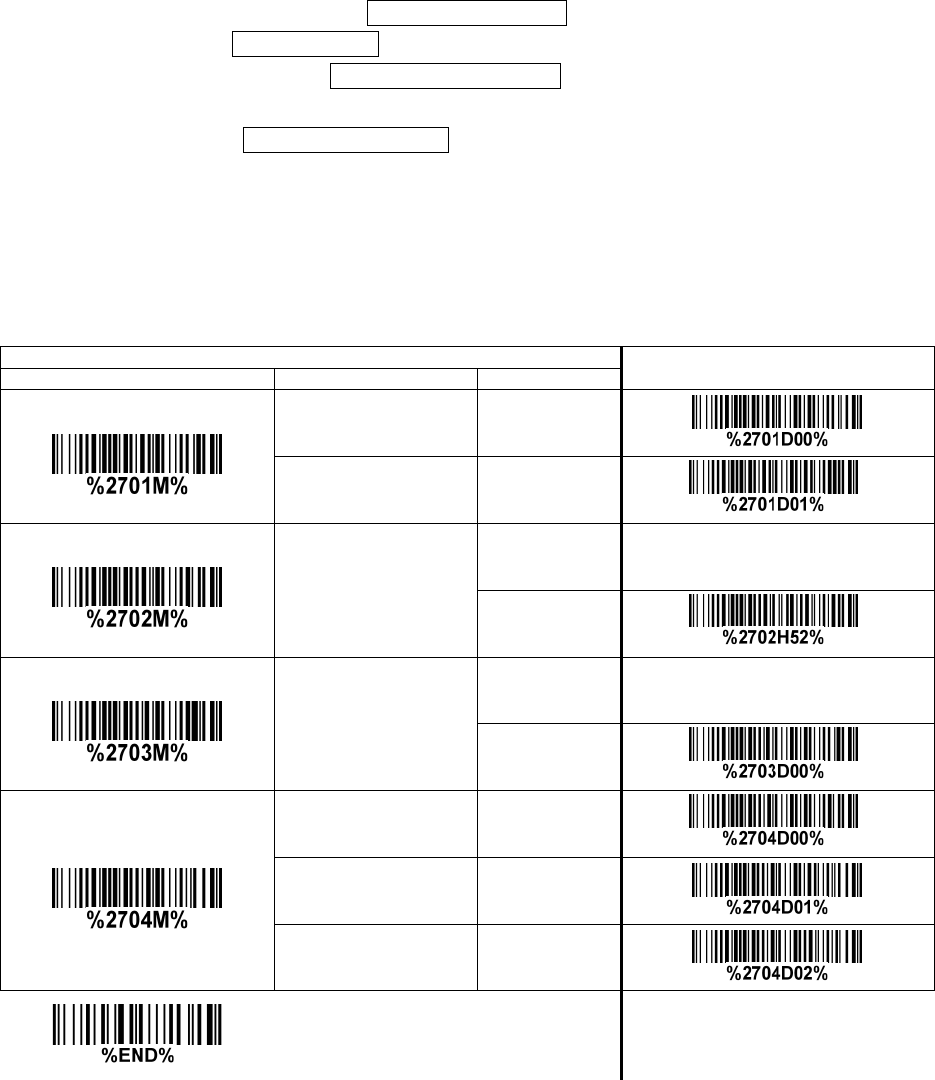
71
3-33 GS1 DataBar (GS1 DataBar Truncated)
GS1 DataBar Truncated is structured and encoded the same as the standard GS1 DataBar format,
except its height is reduced to a 13 modules minimum; while GS1 DataBar should have a height greater
than or equal to 33 modules.
Read:
Format
16 Data digits
Code ID setting: Refer to Code ID setting of 3-14 UPC-A.
Insertion group selection: Refer to Insertion group selection of 3-14 UPC-A.
Conversion:
UCC/EAN 128- Refer to Code ID transmission of 3-43 String transmission, ]Cm will be identified as
AIM ID.
UPC-A or EAN-13- Barcode beginning with a single zero as the first digit has the leading “010”
stripped and the barcode reported as EAN-13. Barcode beginning with two or more zeros but not six
zeros has the leading “0100” stripped and the barcode reported as UPC-A.
Multiple-scan setting
Single-scan setting
Option bar code
Option
Alpha. entry
Read
Disable 00
Enable 01* *
Code ID setting
00-FF16
(ASCII)
00-FF16
<R>* *
Insert group selection
00-66
00-66
00* *
Conversion
None 00* *
UCC/EAN 128 01
UPC-A or EAN-13 02
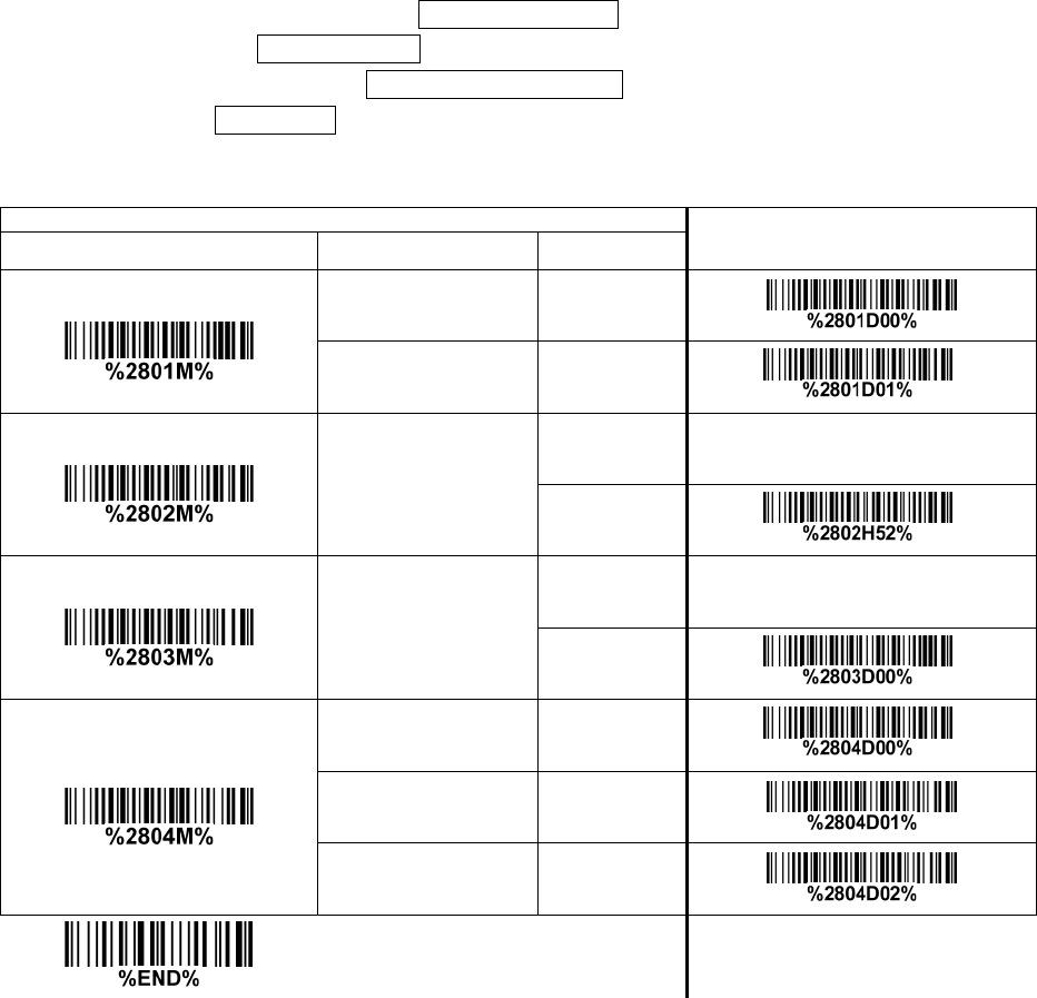
72
3-34 GS1 DataBar Limited
Read:
Format
16 Data digits
Code ID setting: Refer to Code ID setting of 3-14 UPC-A.
Insertion group selection: Refer to Insertion group selection of 3-14 UPC-A.
Conversion: Refer to Conversion of 3-33 GS1 DataBar (GS1 DataBar Truncated).
Multiple-scan setting
Single-scan setting
Option bar code Option Alpha. entry
Read
Disable 00
Enable 01* *
Code ID setting
00-FF16
(ASCII)
00-FF16
<R>* *
Insert group selection
00-66
00-66
00* *
Conversion
None 00* *
UCC/EAN 128 01
UPC-A or EAN-13 02
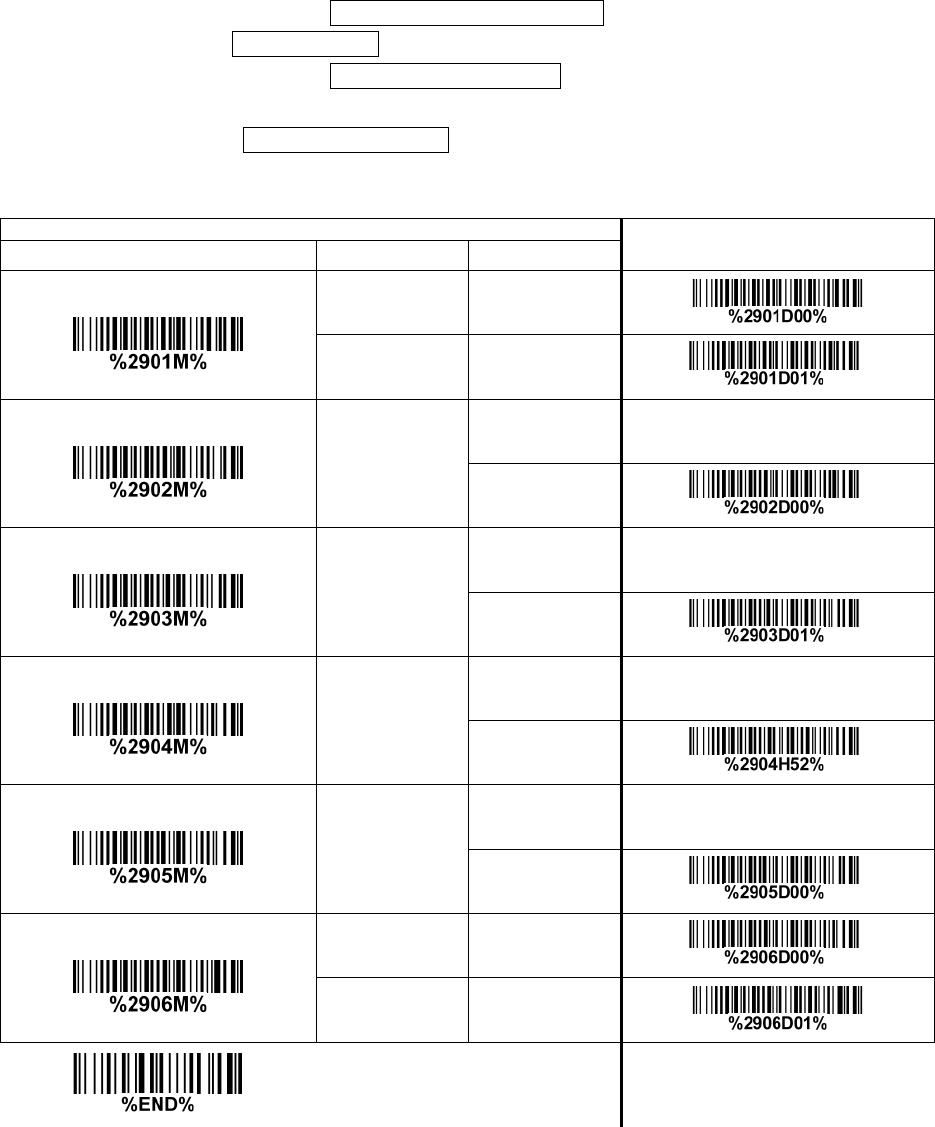
73
3-35 GS1 DataBar Expanded
Read:
Format
Data characters (variable)
Code ID setting: Refer to Code ID setting of 3-14 UPC-A.
Insertion group selection: Refer to Insertion group selection of 3-14 UPC-A.
Conversion:
UCC/EAN 128- Refer to Code ID transmission of 3-43 String transmission, ]Cm will be identified as
AIM ID.
Multiple-scan setting
Single-scan setting
Option bar code Option Alpha. entry
Read
Disable 00
Enable 01* *
Max. code length
00-99
00-99
00* *
Min. code length
00-99
00-99
01* *
Code ID setting
00-FF16
(ASCII)
00-FF16
<R>* *
Insert group selection
00-66
00-66
00* *
Conversion
None 00* *
UCC/EAN 128 01
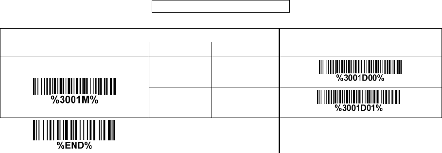
74
3-36 PDF417
Read:
Format
Data characters (variable)
Multiple-scan setting Single-scan setting
Option bar code
Option
Alpha. entry
Read
Disable 00
Enable 01* *
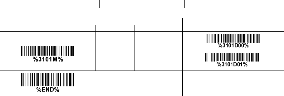
75
3-37 MicroPDF417
Read:
Format
Data characters (variable)
Multiple-scan setting
Single-scan setting
Option bar code
Option
Alpha. entry
Read
Disable 00
Enable 01* *
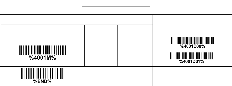
76
3-38 QR Code
Read:
Format
Data characters (variable)
Multiple-scan setting Single-scan setting
Option bar code Option Alpha. entry
Read
Disable 00
Enable 01* *
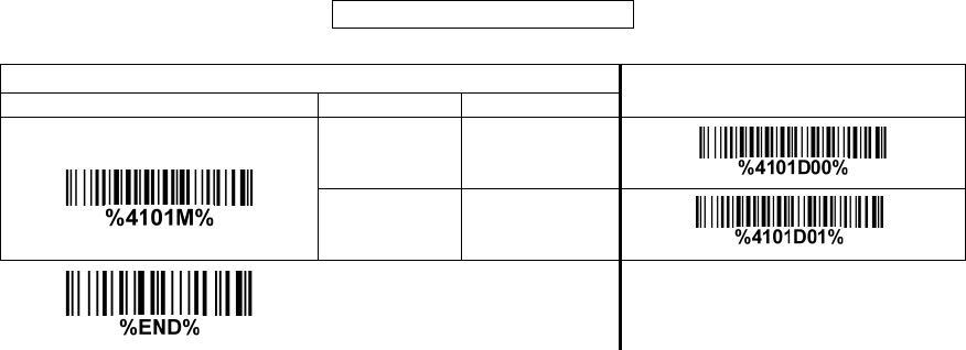
77
3-39 Data Matrix
Read:
Format
Data characters (variable)
Multiple-scan setting
Single-scan setting
Option bar code
Option
Alpha. entry
Read
Disable 00
Enable 01* *
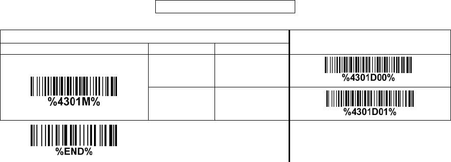
78
3-40 Aztec Code
Read:
Format
Data characters (variable)
Multiple-scan setting
Single-scan setting
Option bar code
Option
Alpha. entry
Read
Disable 00* *
Enable 01
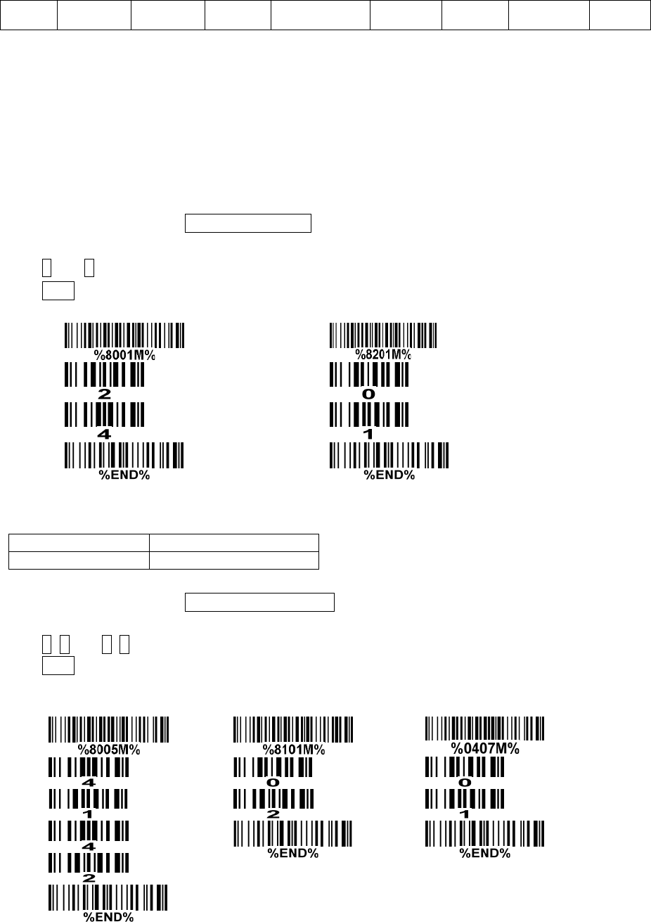
79
3-41 G1-G6 & C1-C2 & FN1 substitution string setting
Format of barcode data transmission:
Prefix Code name Preamble Code ID Code length Code data Code ID Postamble Suffix
Suffix string setting: The <enter > key is represented in different ASCII when it is applied by different
OS. For a Windows/DOS OS, <enter> is represented as <CR><LF> (0x0D 0x0A); for an Apple MAC
OS, <enter> is represented as <CR> (0x0D); for a Linux/Unix OS, <enter> is represented as <LF>
(0x0A).
Prefix/Suffix/Preamble/Postamble string setting:
They are appended to the data automatically when a barcode is decoded.
Example: Add a symbol of “$” as a prefix for all symbols.
Steps:
1) Scan the option barcode of Prefix string setting.
2) Use the ASCII table to find the value of $→24.
3) Scan 2 and 4 from the barcode on the last page.
4) Scan END barcode.
Scanning steps: Scan the following barcodes in order.
Insert G1/G2/G3/G4 string setting: The scanner offers 4 positions and 4 character strings to insert
among the symbol.
Example: Set G1 string to be “AB”.
Original code data
“1 2 3 4 5 6”
Output code data
“1 2 A B 3 4 5 6”
Steps:
1) Scan the option barcode of Insert G1 string setting.
2) Use the ASCII table to find the value of A→41, B→42.
3) Scan 4, 1 and 4, 2 from the barcode on the last page.
4) Scan END barcode.
5) Refer to 3-42 G1-G4 string position & Code ID position.
6) Refer to 3-9 Handheld scan & some global settings.
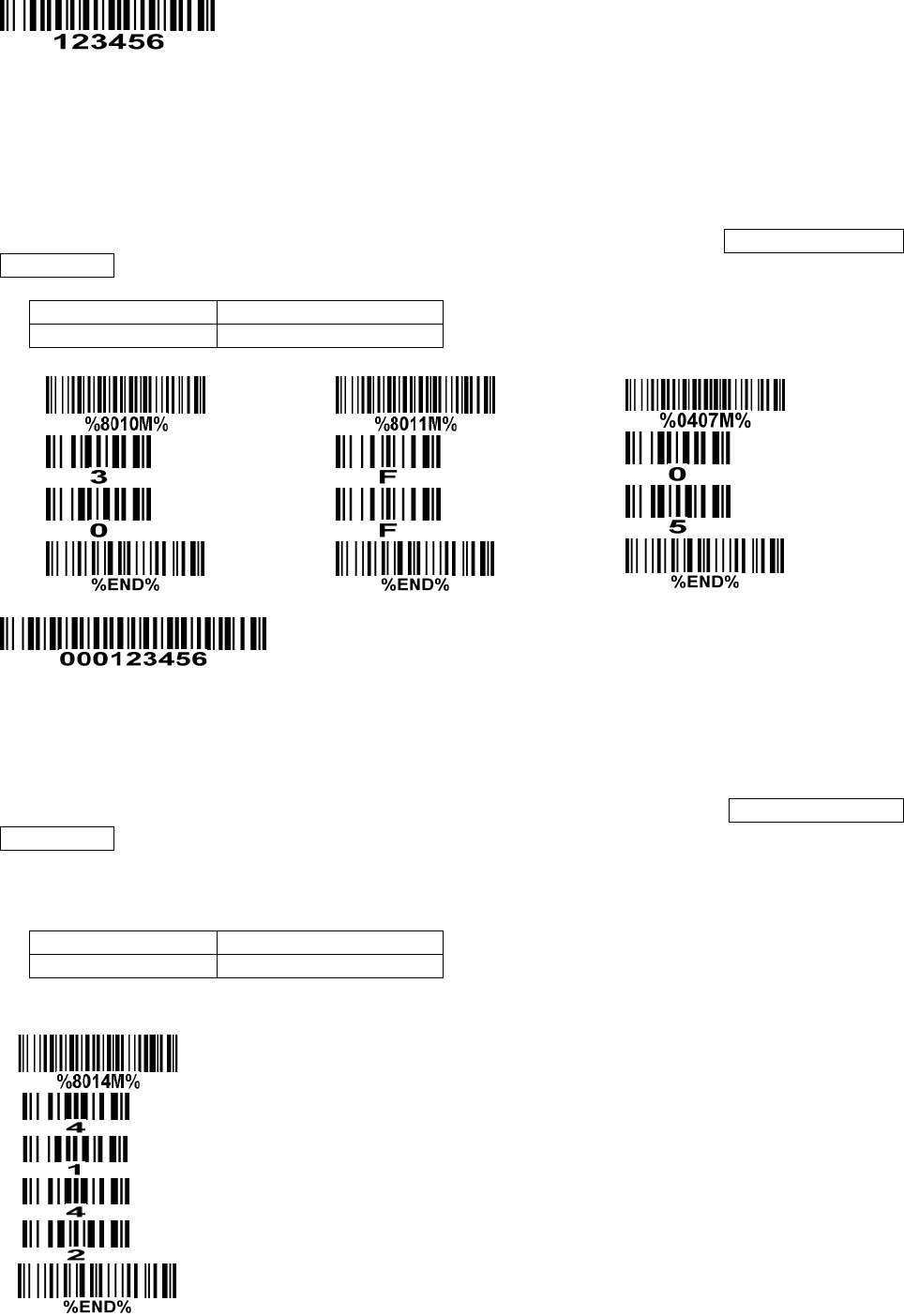
80
Testing barcode:
FN1 substitution string setting: The FN1 character (0x1D) in an UCC/EAN128 barcode, or a Code
128 barcode, or a GS1 DataBar barcode can be substituted with a defined string.
Truncate leading G5 string setting: By setting, a defined leading character or string can be truncated.
Also a single character can be un-defined.
Repeat of a G5 character setting: While G5 is set as a single defined/un-defined character, G5 can
also be set to be repeated. This setting is ignored when the truncate number is more than the barcode
data characters. The option of “FF” for this setting is not active while the option of Truncate leading G5
string setting is “00”.
Example: Truncate all leading zeros for all symbols.
Original code data
“0 0 0 1 2 3 4 5 6”
Output code data
“1 2 3 4 5 6”
Steps: scan the following data in order.
Testing barcode:
Truncate ending G6 string setting: By setting, a defined ending character or string can be truncated.
Also a single character can be un-defined.
Repeat of a G6 character setting: While G5 is set as a single defined/un-defined character, G6 can
also be set to be repeated. This setting is ignored when the truncate number is more than the barcode
data characters. The option of “FF” for this setting is not active while the option of Truncate ending G6
string setting is “00”.
Single character C1/C2 replacement: By setting, a defined character in the data string can be replaced
by another defined character. The C1 and C2 replacement are applied simultaneously.
Example: Replace all the “A” character in a data string to be “B” character.
Original code data
“1 2 3 A 5 A”
Output code data
“1 2 3 B 5 B”
Steps: scan the following barcodes in order. The ASCII value for “A” is 41, and the ASCII value for “B” is
42.
Testing barcode:
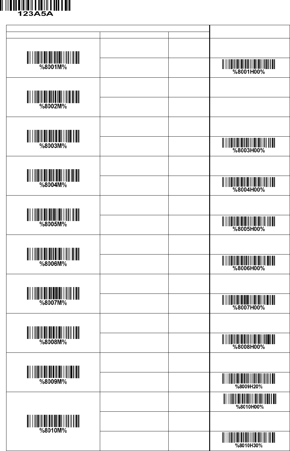
81
Multiple-scan setting
Single-scan setting
Option bar code
Option
Alpha. entry
Prefix string setting
0-22 characters 00-FF16
None 00* *
Suffix string setting
0-22 characters 00-FF16
<ENTER> 0D0A*
Preamble string setting
0-22 characters 00-FF16
None 00* *
Postamble string setting
0-22 characters 00-FF16
None 00* *
Insert G1 string setting
0-22 characters 00-FF16
None 00* *
Insert G2 string setting
0-22 characters 00-FF16
None 00* *
Insert G3 string setting
0-22 characters 00-FF16
None 00* *
Insert G4 string setting
0-22 characters 00-FF16
None 00* *
FN1 substitution string setting
0-4 characters 00-FF16
<SP> 20* *
Truncate leading G5 string setting
A un-defined character 00
1-22 defined characters 01-7F16
<0> 30* *
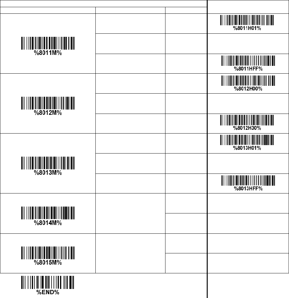
82
Multiple-scan setting
Single-scan setting
Option bar code
Option
Alpha. entry
Repeat of a G5 character setting
Once 01* *
Defined times 01-22
Un-defined times (All) FF
Truncate ending G6 string setting
A un-defined character 00
1-22 defined characters 01-7F16
<0> 30* *
Repeat of a G6 character setting
Once 01* *
Defined times 01-22
Un-defined times (All) FF
Single character C1 replacement
<0000>
0000*
0000-FFFF 16
Single character C2 replacement
<0000>
0000*
0000-FFFF 16
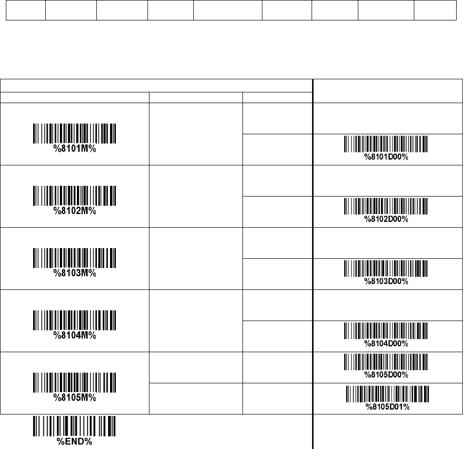
83
3-42 G1-G4 string position & Code ID position
Format of barcode data transmission:
Prefix Code name Preamble Code ID Code length Code data Code ID Postamble Suffix
Insert G1/G2/G3/G4 string position: The scanner offers 4 positions to insert strings among the symbol.
In case of the insertion position is greater than the length of the symbol, the insertion of string is not
effective.
Code ID position: It is allowed to select different positions of code ID placement.
Multiple-scan setting
Single-scan setting
Option bar code
Option
Alpha. entry
Insert G1 string position
00-99
00-99
00* *
Insert G2 string position
00-99
00-99
00* *
Insert G3 string position
00-99
00-99
00* *
Insert G4 string position
00-99
00-99
00* *
Code ID position
Before code data 00* *
After code data 01

84
3-43 String transmission
Note: The information in this chapter is closely related to the chapter of String setting.
Format of barcode data transmission:
Prefix Code name Preamble Code ID Code length Code data Code ID Postamble Suffix
Prefix transmission: By setting Enable, prefix will be appended before the data transmitted.
Suffix transmission: By setting Enable, suffix will be appended after the data is transmitted.
Code name transmission: By setting Enable, code name will be transmitted before code data.
Preamble transmission: By setting Enable, preamble will be appended before the data transmitted.
Postamble transmission: By setting Enable, postamble will be appended after the data is transmitted.
Code ID transmission: Code ID can be transmitted in the format of either Proprietary ID or AIM ID.
Refer to the chapter of Default setting for each barcode.
Code length transmission: The length of code data string can be transmitted before the code data
when Enable is selected. The length is represented by a number with two digits.
Case conversion: The characters within code data or the whole output string can be set in either upper
case or lower case.
FN1 substitution transmission: The scanner supports a FN1 substitution feature for keyboard wedge,
USB and RS-232 interface. The replacement string of FN1 can be chosen by user (see 3-41 G1-G6 &
C1-C2 & FN1 substitution string setting).
All-non-printable-character string transmission with string setting: By setting enable, all string
settings, e.g. Preamble transmission or Insert G1 string setting, are active for an
all-non-printable-character string. Here a non-printable character means a character with ASCII value
between 0x00 to 0x1F.
Transmit the first N data characters only: The scanner supports to only transmit the first N data
characters of a barcode. The number of N can be set as a digit between 1 and 99.
Transmit the last N data characters only: The scanner supports to only transmit the last N data
characters of a barcode. The number of N can be set as a digit between 1 and 99.
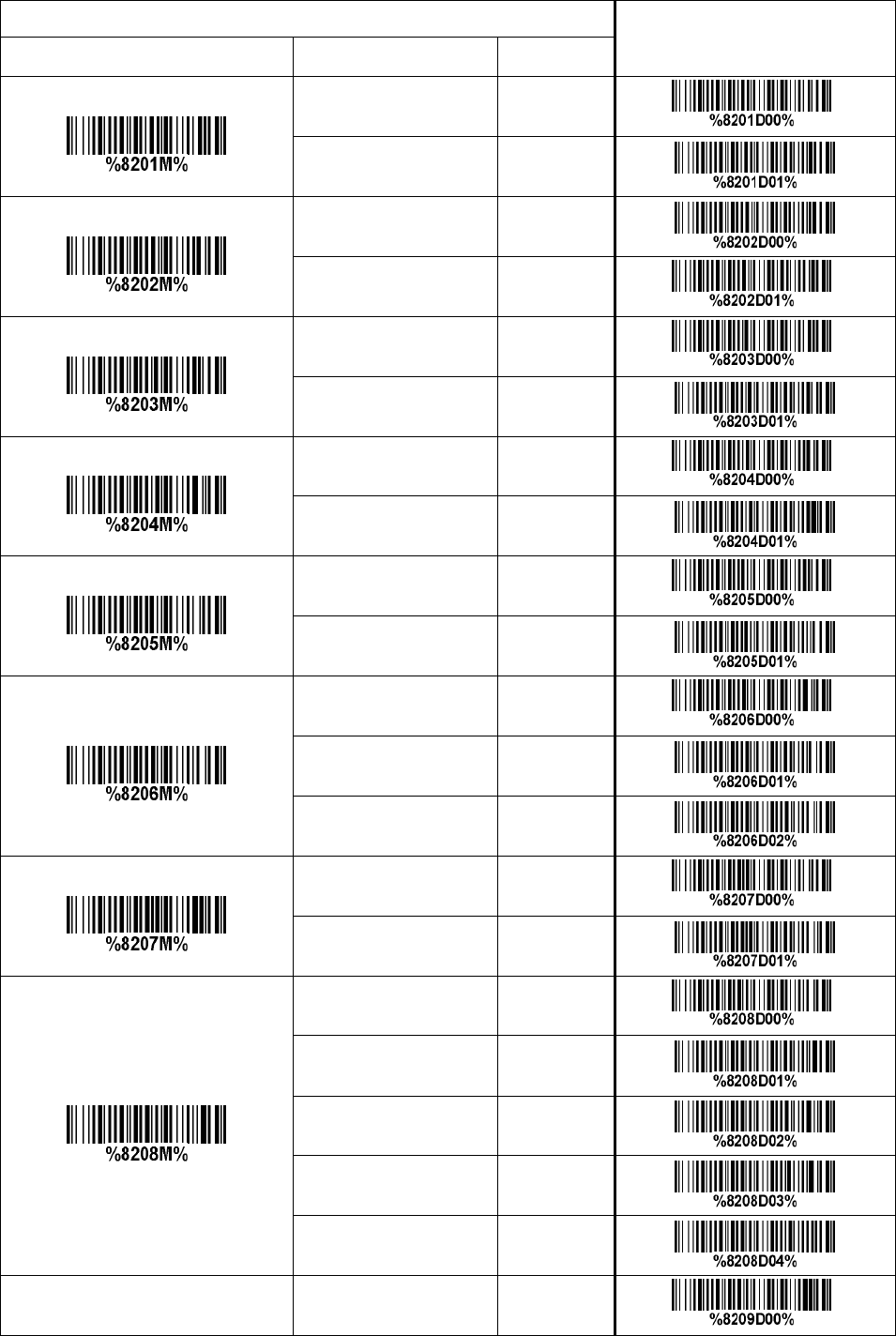
85
Multiple-scan setting Single-scan setting
Option bar code Option
Alpha.
entry
Prefix transmission
Disable 00* *
Enable 01
Suffix transmission
Disable 00
Enable 01*
*
Code name transmission
Disable 00*
*
Enable 01
Preamble transmission
Disable 00*
*
Enable 01
Postamble transmission
Disable 00* *
Enable 01
Code ID transmission
Disable 00* *
Proprietary ID 01
AIM ID 02
Code length transmission
Disable 00* *
Enable 01
Case conversion
Disable 00* *
Upper (data only) 01
Lower (data only) 02
Upper (whole string) 03
Lower (whole string) 04
FN1 substitution transmission Disable 00* *
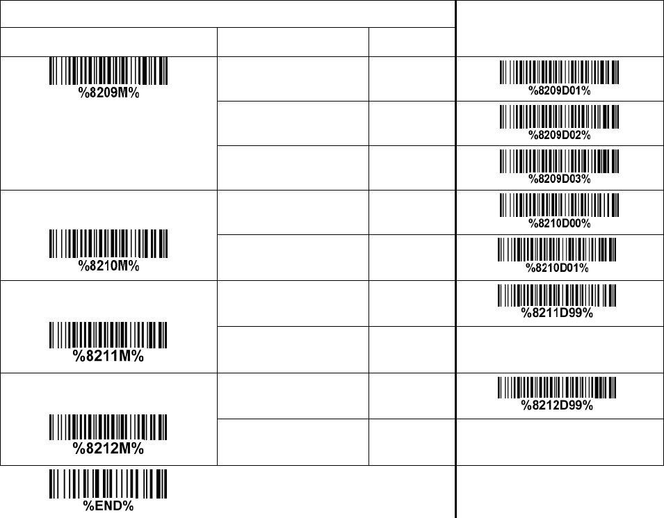
86
Multiple-scan setting Single-scan setting
Option bar code Option
Alpha.
entry
Keyboard wedge/USB 01
RS-232 02
Keyboard wedge
/ USB / RS-232 03
All-non-printable-character string
transmission with string setting
Disable 00
Enable 01* *
Transmit the first N data characters
only
All 99* *
01-99
Transmit the last N data characters
only
All 99* *
01-99
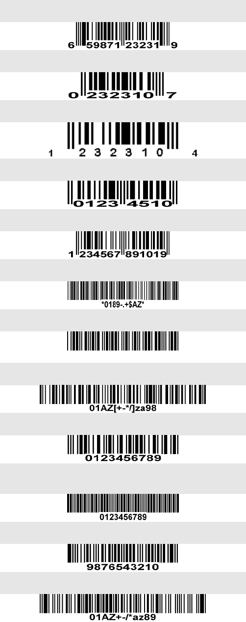
87
4 Test barcode symbols
UPC-A
UPC-E
UPC-E1
EAN-8
EAN-13
Code 39
Code 32
A908765439
Code 128
Interleaved 2 of 5
Industrial 2 of 5
(Default setting: Read disable)
Matrix 2 of 5
Code 93
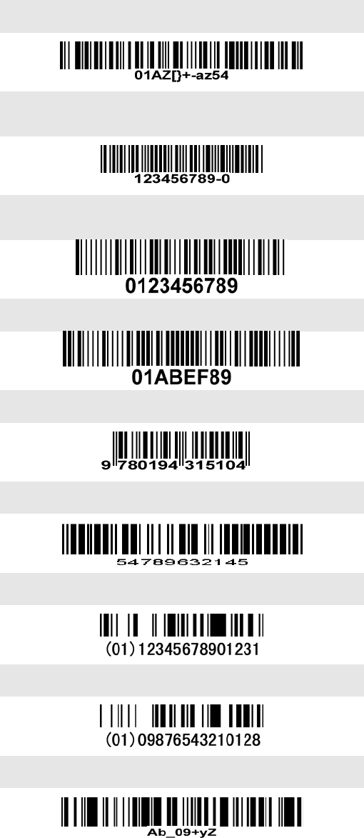
88
UCC/EAN 128
Code 11
(Default setting: Read disable)
MSI/Plessey
(Default setting: Read disable)
UK/Plessey
ISBN/ISSN
China Post
GS1 DataBar (GS1 DataBar Truncated)
GS1 DataBar Limited
GS1 DataBar Expanded

89
PDF417
12=890ab-+%xyz
MicroPDF417
0239+-mdo
QR code
1234567890ABCD-+()&*%^@#$!XYZ
Data Matrix
123890abc-+=&*%^!mdo

90
Aztec Code
12345678901234567890
Han Xin Code
SAMPLE
91
5 Maintenance
Cleaning the scan window is the only maintenance required. A dirty window may affect scanning
accuracy.
1) Do not allow any abrasive material to touch the window.
2) Remove any dirt particles with a damp cloth.
3) Wipe the window using a tissue moistened with water.
4) Do not spray water or other cleaning liquids directly into the window.
5) Use a piece of soft and dry cloth when cleaning the scanner.

92
6 ASCII Table
for keyboard wedge for RS-232
H
L
0 1 0 1
0 Null NUL DLE
1 Up F1 SOH DC1
2 Down F2 STX DC2
3 Left F3 ETX DC3
4 Right F4 EOT DC4
5 PgUp F5 ENQ NAK
6 PgDn F6 ACK SYN
7 F7 BEL ETB
8 Bs F8 BS CAN
9 Tab F9 HT EM
A F10 LF SUB
B Home Esc VT ESC
C End F11 FF FS
D Enter F12 CR GS
E Insert Ctrl+ SO RS
F Delete Alt+ SI US
Notes: The 2nd and the 3rd columns above are used for keyboard wedge only.
H
L
2 3 4 5 6 7
0 SP 0 @ P ` p
1 ! 1 A Q a q
2 “ 2 B R b r
3 # 3 C S c s
4 $ 4 D T d t
5 % 5 E U e u
6 & 6 F V f v
7 ‘ 7 G W g w
8 ( 8 H X h x
9 ) 9 I Y i y
A * : J Z j z
B + ; K [ k {
C , < L \ l |
D - = M ] m }
E . > N ^ n ~
F / ? O _ o DEL
Example: ASCII “A” = “41”.

93
7 Barcode representing non-printable character
Notes to make the following barcode:
1. According to different barcode printing software, the method of printing following barcode is different.
2. If using CODESOFT software, firstly read the information through “Help→Index→Code128→Special
input syntax”. Also refer to ASCII table. For example, if we wish to make “F1” barcode, select
“Code128”, then select “CODE A” type, and input “{DC1}” as data.
Up ↑
Down ↓
Left ←
Right →
Page Up
Page Down
Backspace
Tab
Home
End
Enter
Insert
Delete
F1
F2
F3
F4
F5
F6
F7
F8
F9
F10
Esc
F11
F12

94
8 Return default parameters
8-1 CS2290 return default parameters
All parameters of handheld unit return to default setting
WARNING: If you wish to return all parameters of the handheld unit, including radio communication
setting, to default setting, please scan the barcode above.
All parameters of cradle return to default setting
WARNING: If you wish to return all parameters of the cradle, including radio communication
setting, to default setting, please scan the barcode above.
Some parameters of handheld unit return to default setting
WARNING: If you wish to return all parameters of the handheld unit, excluding radio
communication setting, to default setting, please scan the barcode above.
Some parameters of cradle return default value initialization
WARNING: If you wish to return all parameters of the cradle, excluding radio communication
setting, to default setting, please scan the barcode above.
Turn off handheld unit
If you wish to turn off the handheld unit, please scan the barcode above. If you want to turn on the
handheld unit again, please keep the trigger key being pressing for 2 seconds.
If you want to turn off the handheld unit via trigger key, please press and hold the trigger key, after the
laser beam turns off, wait for another 5 seconds, the handheld unit will be turned off, then you can
release the trigger key at this moment.

95
8-2 CS2290-BT return default parameters
Some parameters of handheld unit return to default setting
WARNING: If you wish to return all parameters of the handheld unit, to default setting, please scan
the barcode above.
Some parameters of cradle return default value initialization
WARNING: If you wish to return all parameters of the cradle, please scan the barcode above.
Turn off handheld unit
If you wish to turn off the handheld unit, please scan the barcode above. If you want to turn on the
handheld unit again, please keep the trigger key being pressing for 2 seconds.
If you want to turn off the handheld unit via trigger key, please press and hold the trigger key, after the
laser beam turns off, wait for another 5 seconds, the handheld unit will be turned off, then you can
release the trigger key at this moment.

96
9 Display firmware version & radio communication setting
9-1 CS2290 display firmware version & radio communication setting
Cradle firmware version display
If you wish to display the firmware version of the cradle, please scan the barcode above.
Handheld unit firmware version display
If you wish to display the firmware version of the handheld unit, please scan the barcode above.
Cradle radio communication setting display
If you wish to display the radio communication setting of the cradle, please scan the barcode above.
Handheld unit radio communication setting display
If you wish to display the radio communication setting of the handheld unit, please scan the barcode
above.

97
9-2 CS2290-BT display firmware version
Cradle firmware version display
If you wish to display the firmware version of the cradle, please scan the barcode above.
Handheld unit firmware version display
If you wish to display the firmware version of the handheld unit, please scan the barcode above.

98
10 Configuration alphanumeric entry barcode
To finish parameter setting, please scan the bar code below.
Warning:
changes or modifications not expressly approved by the party responsible for
compliance could void the user’s authority to operate the equipment.
This device complies with Part 15 of the FCC Rules. Operation is subject to the
following two conditions: (1) this device may not cause harmful interference, and
(2) this device must accept any interference received, including interference that
may cause undesired operation. changes or modifications not expressly approved
by the party responsible for compliance could void the user's authority to operate
the equipment.
NOTE: This equipment has been tested and found to comply with the limits for a
Class B digital device, pursuant to Part 15 of the FCC Rules. These limits are
designed to provide reasonable protection against harmful interference in a
residential installation. This equipment generates, uses and can radiate radio
frequency energy and, if not installed and used in accordance with the
instructions, may cause harmful interference to radio communications. However,
there is no guarantee that interference will not occur in a particular installation.
If this equipment does cause harmful interference to radio or television reception,
which can be determined by turning the equipment off and on, the user is
encouraged to try to correct the interference by one or more of the following
measures:
-- Reorient or relocate the receiving antenna.
-- Increase the separation between the equipment and receiver.
--Connect the equipment into an outlet on a circuit different
from that to which the receiver is connected.
--Consult the dealer or an experienced radio/TV technician for help.
NOTE: This device and its antenna(s) must not be coÿlocated or operation in
conjunction with any other antenna or transmitter.
10