Mindray BIO Medical electronics TD608FE Telemetry Transmitter User Manual 608M FDA
Shenzhen Mindray BIO-Medical electronics Co.,LTD. Telemetry Transmitter 608M FDA
User Manual
BeneVision TMS60
Telemetry Monitoring System
Operator’s Manual

Introduction
TMS60 Operator’s Manual I
© Copyright 2015 Shenzhen Mindray Bio-Medical Electronics Co., Ltd. All rights reserved.
For this Operator’s Manual, the issue date is 2015-06.

Intellectual Property Statement Introduction
II TMS60 Operator’s Manual
Intellectual Property Statement
SHENZHEN MINDRAY BIO-MEDICAL ELECTRONICS CO., LTD. (hereinafter called Mindray)
owns the intellectual property rights to this Mindray product and this manual. This
manual may refer to information protected by copyrights or patents and does not
convey any license under the patent rights of Mindray, nor the rights of others.
Mindray intends to maintain the contents of this manual as confidential information.
Disclosure of the information in this manual in any manner whatsoever without the
written permission of Mindray is strictly forbidden.
Release, amendment, reproduction, distribution, rental, adaption and translation of this
manual in any manner whatsoever without the written permission of Mindray is strictly
forbidden.
, , and are the registered trademarks or
trademarks owned by Mindray in China and other countries. All other trademarks that
appear in this manual are used only for editorial purposes without the intention of
improperly using them. They are the property of their respective owners.
Manufacturer’s Responsibility
Contents of this manual are subject to changes without prior notice.
All information contained in this manual is believed to be correct. Mindray shall not be
liable for errors contained herein nor for incidental or consequential damages in
connection with the furnishing, performance, or use of this manual.
Mindray is responsible for the effects on safety, reliability and performance of this
product, only if:
■all installation operations, expansions, changes, modifications and repairs of this
product are conducted by Mindray authorized personnel;
■the electrical installation of the relevant room complies with the applicable
national and local requirements;
■the product is used in accordance with the instructions for use.

Introduction Warranty
TMS60 Operator’s Manual III
Warranty
Mindray warrants that components within its products will be free from defects in
workmanship and materials for a period of three years from the date of purchase except
that disposable or one-time use products are warranted to be free from defects in
workmanship and materials up to a date one year from the date of purchase or the date
of first use, whichever is sooner.
This warranty does not cover consumable items such as, but not limited to, batteries,
external cables, and sensors.
Mindray shall not be liable for any incidental, special, or consequential loss, damage, or
expense directly or indirectly arising from the use of its products. Liability under this
warranty and the buyer’s exclusive remedy under this warranty is limited to servicing or
replacing the affected products, at Mindray option, at the factory or at an authorized
distributor, for any product which shall under normal use and service appear to Mindray
to have been defective in material or workmanship. Recommended preventative
maintenance, as prescribed in the service manual, is the responsibility of the user and is
not covered by this warranty.
No agent, employee, or representative of Mindray has any authority to bind Mindray to
any affirmation, representation, or warranty concerning its products, and any
affirmation, representation or warranty made by any agent, employee, or representative
shall not be enforceable by buyer or user.
THIS WARRANTY IS EXPRESSLY IN LIEU OF, AND MINDRAY EXPRESSLY DISCLAIMS, ANY
OTHER EXPRESS OR IMPLIED WARRANTIES, INCLUDING ANY IMPLIED WARRANTY OF
MERCHANTABILITY, NON-INFRINGEMENT, OR FITNESS FOR A PARTICULAR PURPOSE,
AND OF ANY OTHER OBLIGATION ON THE PART OF MINDRAY.
Damage to any product or parts through misuse, neglect, accident, or by affixing any
non-standard accessory attachments, or by any customer modification voids this
warranty. Mindray makes no warranty whatsoever in regard to trade accessories, such
being subject to the warranty of their respective manufacturers.
A condition of this warranty is that the equipment or accessories which are claimed to
be defective be returned when authorized, freight prepaid to Mindray DS USA, Inc.,
Mahwah, New Jersey 07430 or its authorized representative. Mindray shall not have any
responsibility in the event of loss or damage in transit.
WARNING
•Only skilled/trained clinical professionals should operate this equip-
ment.
•It is important for the hospital or organization that employs this equip-
ment to carry out a reasonable service/maintenance plan. Neglect of this
may result in machine breakdown or personal injury.

Company Contact Introduction
IV TMS60 Operator’s Manual
Exemptions
Mindray's obligation or liability under this warranty does not include any transportation
or other charges or liability for direct, indirect or consequential damages or delay
resulting from the improper use or application of the product or the use of parts or
accessories not approved by Mindray or repairs by people other than Mindray
authorized personnel.
This warranty does not extend to:
■Malfunction or damage caused by improper use or man-made failure.
■Malfunction or damage caused by unstable or out-of-range power input.
■Malfunction or damage caused by force majeure events, such as (i) flood, fire and
earthquake or other similar elements of nature or acts of God; (ii) riots, war, civil
disorders, rebellions, or revolutions in any country; or (iii) any other cause beyond
the reasonable control of Mindray.
■Malfunction or damage caused by improper operation or repair by unqualified or
unauthorized service people.
■Malfunction of the instrument or part whose serial number is not legible.
■Others not caused by instrument or part itself.
Company Contact
Manufacturer: Shenzhen Mindray Bio-Medical Electronics Co., Ltd.
Address: Mindray Building, Keji 12th Road South, Hi-tech industrial park, Nanshan, Shenzhen
518057, P.R.China
Website: www.mindray.com
E-mail Address: service@mindray.com
Tel: +86 755 81888998
Fax: +86 755 26582680
Distributor: Mindray DS USA, Inc.
Address: 800 MacArthur Boulevard, Mahwah, New Jersey 07430 USA
Tel: 1.800.288.2121, 1.201.995.8000
Website: www.mindray.com
EC-Representative: Shanghai International Holding Corp. GmbH (Europe)
Address: Eiffestraβe 80, 20537 Hamburg, Germany
Tel: 0049-40-2513175

Introduction Preface
TMS60 Operator’s Manual V
Preface
Manual Purpose
This manual contains the instructions necessary to operate the product safely and in
accordance with its function and intended use. Observance of this manual is a
prerequisite for proper product performance and correct operation and ensures patient
and operator safety.
This manual is based on the maximum configuration and therefore some contents may
not apply to your product. If you have any questions, please contact Mindray.
This manual is an integral part of the product. It should always be kept close to the
equipment so that it can be obtained conveniently when needed.
Intended Audience
This manual is geared for clinical professionals who are expected to have a working
knowledge of medical procedures, practices and terminology as required for monitoring
of critically ill patients.
Illustrations
All illustrations in this manual serve as examples only. They may not necessarily reflect
the setup or data displayed on your patient monitor.
Conventions
■Italic text is used in this manual to quote the referenced chapters or sections.
■[ ] is used to enclose screen texts.
■→ is used to indicate operational procedures.
Fax: 0049-40-255726

Preface Introduction
VI TMS60 Operator’s Manual
This page intentionally left blank.

TMS60 Operator’s Manual 1
Contents
1 Safety ........................................................................................................................................ 1 - 1
1.1 Safety Information ..................................................................................................................................... 1 - 2
1.1.1 Warnings ........................................................................................................................................1 - 3
1.1.2 Cautions ..........................................................................................................................................1 - 4
1.1.3 Notes ................................................................................................................................................1 - 5
1.2 Equipment Symbols ..................................................................................................................................1 - 5
2 General Product Description ................................................................................................... 2 - 1
2.1 Intended Use ................................................................................................................................................2 - 2
2.2 Applied Parts ................................................................................................................................................2 - 2
2.3 Key Features .................................................................................................................................................2 - 2
2.4 System Components .................................................................................................................................2 - 3
2.5 TD60 Physical View .................................................................................................................................... 2 - 3
2.6 Antenna Array ..............................................................................................................................................2 - 5
2.7 Telemetry Receiver (RC60) ...................................................................................................................... 2 - 5
2.8 Touch Screen Display ................................................................................................................................ 2 - 5
2.8.1 Display Screen ..............................................................................................................................2 - 6
2.8.2 On-Screen Keyboard .................................................................................................................. 2 - 7
3 Getting Started ......................................................................................................................... 3 - 1
3.1 Unpacking and Checking ........................................................................................................................3 - 2
3.2 Environmental Requirements ................................................................................................................ 3 - 3
3.3 Connecting the ECG Leadwire ...............................................................................................................3 - 4
3.4 Installing the Batteries ..............................................................................................................................3 - 5
3.4.1 Installing the Lithium-ion Rechargeable Battery ............................................................. 3 - 6
3.4.2 Installing the AA Batteries ........................................................................................................3 - 7
3.5 Powering On the Unit ...............................................................................................................................3 - 8
3.6 Understanding Touch Gestures ............................................................................................................3 - 9
3.7 Basic Operations .........................................................................................................................................3 - 9
3.7.1 Understanding the Screen Display Orientation .............................................................3 - 10
3.7.2 Browsing the Screen Display ................................................................................................3 - 10
3.7.3 Switching the Screen Display Orientation .......................................................................3 - 10
3.7.4 Flipping the Landscape Display ...........................................................................................3 - 10
3.7.5 Displaying the Quick Keys Area ...........................................................................................3 - 11
3.7.6 Entering the Main Menu .........................................................................................................3 - 11
3.7.7 Turning the Display Off ...........................................................................................................3 - 12
3.7.8 Turning the Display On ...........................................................................................................3 - 13
3.7.9 Unlocking the Screen ..............................................................................................................3 - 13

2 TMS60 Operator’s Manual
3.7.10 Acknowledging the Nurse Call ..........................................................................................3 - 13
3.8 Using the Pouch ........................................................................................................................................3 - 14
3.8.1 Securing the Pouch ..................................................................................................................3 - 14
4 User Configurations ................................................................................................................. 4 - 1
4.1 Introduction ..................................................................................................................................................4 - 2
4.2 Configuring the Display ...........................................................................................................................4 - 2
4.2.1 Setting the Default Display Orientation .............................................................................4 - 2
4.2.2 Understanding Portrait Orientation Display Rules ......................................................... 4 - 2
4.2.3 Setting the Portrait Display .....................................................................................................4 - 2
4.2.4 Understanding Landscape Orientation Display Rules ...................................................4 - 3
4.2.5 Setting the Landscape Display ...............................................................................................4 - 4
4.2.6 Setting the Display Brightness ...............................................................................................4 - 4
4.3 Configuring the Audio Volume ............................................................................................................. 4 - 5
5 Patient Management ............................................................................................................... 5 - 1
5.1 Introduction ..................................................................................................................................................5 - 2
5.2 Admitting a Patient .................................................................................................................................... 5 - 2
5.3 Changing the Patient Category ............................................................................................................. 5 - 2
5.4 Placing a Device in Standby ...................................................................................................................5 - 3
5.5 Resume Monitoring ...................................................................................................................................5 - 4
5.6 Discharging the Patient ............................................................................................................................ 5 - 4
5.6.1 Selecting the [Discharge Patient] menu .............................................................................5 - 4
5.6.2 Restarting the TD60 ...................................................................................................................5 - 5
6 Alarms ....................................................................................................................................... 6 - 1
6.1 Introduction ..................................................................................................................................................6 - 2
6.2 Alarm Categories ........................................................................................................................................ 6 - 2
6.3 Alarm Levels .................................................................................................................................................6 - 2
6.4 Alarm Indicators ..........................................................................................................................................6 - 3
6.4.1 Alarm Light .................................................................................................................................... 6 - 3
6.4.2 Alarm Tones ..................................................................................................................................6 - 3
6.4.3 Alarm Messages ...........................................................................................................................6 - 4
6.4.4 Alarm Status Symbols ................................................................................................................ 6 - 4
6.5 Configuring the Alarms ............................................................................................................................6 - 5
6.6 Resetting the Alarms ................................................................................................................................. 6 - 5
7 Monitoring ECG ........................................................................................................................ 7 - 1
7.1 Introduction ..................................................................................................................................................7 - 2
7.2 Safety ..............................................................................................................................................................7 - 2
7.3 Preparation for Monitoring ECG ........................................................................................................... 7 - 3
7.3.1 Preparing the Patient’s Skin .................................................................................................... 7 - 3
7.3.2 Positioning the Electrodes .......................................................................................................7 - 3

TMS60 Operator’s Manual 3
7.3.3 Setting ECG Lead Labeling ......................................................................................................7 - 5
7.3.4 Placing the Electrodes ............................................................................................................... 7 - 5
7.3.5 Checking the Lead Placement ................................................................................................ 7 - 9
7.3.6 Checking the Paced Status ....................................................................................................7 - 10
7.4 Changing the ECG Settings ...................................................................................................................7 - 11
7.4.1 Configuring the ECG Setup ...................................................................................................7 - 11
7.4.2 ECG Leadwire Types .................................................................................................................7 - 12
7.4.3 Configuring the ECG Waveforms ........................................................................................7 - 12
7.4.4 Configuring the Pacer .............................................................................................................7 - 13
7.4.5 Configuring the ECG Waveform Size .................................................................................7 - 14
7.5 Understanding the ECG Display ..........................................................................................................7 - 14
7.5.1 HR Digital Area ...........................................................................................................................7 - 14
7.5.2 About the HR Digital Area ......................................................................................................7 - 14
7.5.3 ECG Waveform Area .................................................................................................................7 - 15
7.5.4 About the ECG Waveform Area ............................................................................................7 - 15
8 Monitoring SpO2 (Optional) .................................................................................................... 8 - 1
8.1 Introduction ..................................................................................................................................................8 - 2
8.2 Measurement Limitations .......................................................................................................................8 - 2
8.3 Safety ..............................................................................................................................................................8 - 3
8.4 Connecting the SpO2 Module ...............................................................................................................8 - 4
8.5 Changing the SpO2 Settings ..................................................................................................................8 - 5
8.5.1 Configuring the SpO2 Setup ................................................................................................... 8 - 5
8.5.2 Configuring the SpO2 Waveform ..........................................................................................8 - 8
8.6 SpO2 Measurement ................................................................................................................................... 8 - 8
8.6.1 Identifying SpO2 Modules .......................................................................................................8 - 8
8.6.2 Applying the Sensor ...................................................................................................................8 - 8
8.7 Understanding the SpO2 Display .......................................................................................................8 - 10
8.7.1 SpO2 Digital Area ......................................................................................................................8 - 10
8.7.2 About the SpO2 Digital Area ................................................................................................8 - 11
8.7.3 SpO2 Waveform Area ..............................................................................................................8 - 11
8.7.4 About the SpO2 Waveform Area .........................................................................................8 - 11
8.8 Masimo Information ................................................................................................................................8 - 12
9 Monitoring with the TD60 at the CS ....................................................................................... 9 - 1
9.1 Introduction ..................................................................................................................................................9 - 2
9.2 Physiological Alarms ................................................................................................................................. 9 - 2
9.2.1 Factory Default Parameter Alarm Limits .............................................................................9 - 3
9.2.2 Parameter Alarm Responses ................................................................................................... 9 - 4
9.2.3 Factory Default Parameter Alarm Settings ........................................................................9 - 5
9.2.4 Factory Default Arrhythmia Alarm Settings ......................................................................9 - 6
9.2.5 Arrhythmia Threshold Settings ............................................................................................9 - 10
9.3 ECG Monitoring .........................................................................................................................................9 - 12
9.3.1 HR Settings ..................................................................................................................................9 - 12

4 TMS60 Operator’s Manual
9.3.2 Waveform Setup ........................................................................................................................9 - 13
9.3.3 Other Settings ............................................................................................................................9 - 15
9.3.4 ECG Display .................................................................................................................................9 - 16
9.4 QT Monitoring ...........................................................................................................................................9 - 18
9.4.1 Measurement Limitations ......................................................................................................9 - 18
9.4.2 QT Settings ..................................................................................................................................9 - 18
9.4.3 QT View Menu (Only for Mindray ECG Algorithm) ........................................................9 - 20
9.4.4 QT Display ....................................................................................................................................9 - 21
9.5 ST Monitoring ............................................................................................................................................9 - 22
9.5.1 Measurement Limitations ......................................................................................................9 - 23
9.5.2 ST Settings ...................................................................................................................................9 - 23
9.5.3 Adjusting ST Measurement Points .....................................................................................9 - 24
9.5.4 ST Display .....................................................................................................................................9 - 25
9.5.5 ST Segment Display ..................................................................................................................9 - 26
9.6 Arrhythmia Monitoring ..........................................................................................................................9 - 27
9.6.1 Measurement Limitations ......................................................................................................9 - 27
9.6.2 Understanding the Arrhythmia Events .............................................................................9 - 27
9.6.3 Arrhythmia Settings .................................................................................................................9 - 30
9.6.4 Relearning ....................................................................................................................................9 - 30
9.6.5 Configuring the QRS Threshold ...........................................................................................9 - 31
9.7 SpO2 Monitoring ......................................................................................................................................9 - 33
9.7.1 Measurement Limitations ......................................................................................................9 - 33
9.7.2 SpO2 Settings .............................................................................................................................9 - 33
9.7.3 SpO2 Display ...............................................................................................................................9 - 34
10 Configuring the TD60 .......................................................................................................... 10 - 1
10.1 Introduction .............................................................................................................................................10 - 2
10.2 Maintenance Menu ...............................................................................................................................10 - 2
10.2.1 Entering the Maintenance menu ......................................................................................10 - 2
10.2.2 Configuring the General Menu ..........................................................................................10 - 2
10.2.3 Configuring the Alarms Menu ...........................................................................................10 - 3
10.2.4 Quick Keys Menu ....................................................................................................................10 - 5
10.2.5 Configuring the Defaults Menu .........................................................................................10 - 6
10.2.6 Transferring a Configuration ..............................................................................................10 - 7
10.2.7 Screen Lock Menu ..................................................................................................................10 - 8
10.2.8 Changing the Passwords .....................................................................................................10 - 9
10.2.9 Changing the Device Name ................................................................................................10 - 9
10.2.10 Demo Mode ...........................................................................................................................10 - 9
10.2.11 Service Menu .........................................................................................................................10 - 9
11 Battery ................................................................................................................................... 11 - 1
11.1 Introduction .............................................................................................................................................11 - 2
11.2 Safety ..........................................................................................................................................................11 - 2
11.3 Installing the Battery .............................................................................................................................11 - 3
11.4 Checking the Battery Charge Status ...............................................................................................11 - 4

TMS60 Operator’s Manual 5
11.5 Removing the Battery ...........................................................................................................................11 - 4
11.6 Charging the Rechargeable Lithium-ion Battery ........................................................................11 - 5
11.7 Storing the Batteries .............................................................................................................................11 - 6
11.7.1 Storing Rechargeable Lithium-ion Battery ....................................................................11 - 6
11.7.2 Storing AA Batteries ...............................................................................................................11 - 6
11.8 Maintaining the Rechargeable Lithium-ion Battery ..................................................................11 - 7
11.9 Disposing of the Batteries ...................................................................................................................11 - 8
11.9.1 Disposing of the Rechargeable Lithium-ion Battery .................................................11 - 8
11.9.2 Disposing of the AA Batteries ............................................................................................11 - 8
12 Troubleshooting ................................................................................................................... 12 - 1
12.1 General Problems ...................................................................................................................................12 - 2
12.1.1 Troubleshooting Tools .........................................................................................................12 - 2
12.1.2 Problem List ..............................................................................................................................12 - 2
12.2 Physiological Alarm Messages at the CS .......................................................................................12 - 3
12.3 Technical Alarm Messages at the TD60 .........................................................................................12 - 5
13 Cleaning and Disinfecting ................................................................................................... 13 - 1
13.1 Introduction .............................................................................................................................................13 - 2
13.2 Safety Information .................................................................................................................................13 - 2
13.3 Cleaning of the TD60 ............................................................................................................................13 - 3
13.4 Cleaning the Reusable ECG Leadwires, SpO2 Modules and Sensors ..................................13 - 4
13.5 Cleaning the Battery and Battery Compartment ........................................................................13 - 5
13.6 Disinfection ..............................................................................................................................................13 - 5
13.7 Sterilization ..............................................................................................................................................13 - 5
14 Maintenance ......................................................................................................................... 14 - 1
14.1 Introduction .............................................................................................................................................14 - 2
14.2 Safety ..........................................................................................................................................................14 - 2
14.3 Regular Check ..........................................................................................................................................14 - 3
14.3.1 Power-on Test ..........................................................................................................................14 - 3
14.3.2 Battery Check ...........................................................................................................................14 - 3
14.4 Maintenance and Testing Schedule ................................................................................................14 - 4
14.5 Checking the System Information ...................................................................................................14 - 4
14.6 Verifying the ECG at the TD60 ...........................................................................................................14 - 4
15 Accessories ............................................................................................................................ 15 - 1
15.1 ECG Accessories ......................................................................................................................................15 - 2
15.1.1 ECG Electrodes .........................................................................................................................15 - 2
15.1.2 ECG Leadsets ............................................................................................................................15 - 3
15.2 SpO2 Accessories ...................................................................................................................................15 - 3
15.2.1 Masimo SpO2 Module ..........................................................................................................15 - 3

6 TMS60 Operator’s Manual
15.2.2 Masimo SpO2 Sensor ............................................................................................................15 - 4
15.2.3 Nonin SpO2 Module ..............................................................................................................15 - 4
15.2.4 Nonin SpO2 Sensor ................................................................................................................15 - 4
15.3 Miscellaneous ..........................................................................................................................................15 - 5
A Product Specifications .............................................................................................................A - 1
A.1 Classifications ..............................................................................................................................................A - 2
A.2 Environmental Specifications ................................................................................................................A - 2
A.3 Power Supply Specifications ..................................................................................................................A - 3
A.3.1 TD60 ................................................................................................................................................A - 3
A.3.2 RC60 .................................................................................................................................................A - 3
A.3.3 Central Charger ...........................................................................................................................A - 4
A.4 Physical Specifications .............................................................................................................................A - 4
A.4.1 TD60 ................................................................................................................................................A - 4
A.4.2 RC60 .................................................................................................................................................A - 4
A.4.3 Central Charger ...........................................................................................................................A - 4
A.5 Hardware Specifications ..........................................................................................................................A - 5
A.5.1 TD60 ................................................................................................................................................A - 5
A.5.2 RC60 .................................................................................................................................................A - 6
A.5.3 Central Charger ...........................................................................................................................A - 6
A.6 Wireless Specification ...............................................................................................................................A - 7
A.6.1 Technique Specification ...........................................................................................................A - 7
A.6.2 Implemented Functions ...........................................................................................................A - 7
A.6.3 Function Specification ..............................................................................................................A - 8
A.7 Mindray Patient Area Network (PAN) Specification ......................................................................A - 9
A.7.1 Technique Specification ...........................................................................................................A - 9
A.7.2 Implemented Function .............................................................................................................A - 9
A.7.3 Function Specification ..............................................................................................................A - 9
A.8 Measurement Specifications ...............................................................................................................A - 10
A.8.1 ECG ................................................................................................................................................ A - 10
A.8.2 SpO2 .............................................................................................................................................A - 14
B EMC ............................................................................................................................................ B - 1
C FCC Compliance ........................................................................................................................ C - 1
D Symbols and Abbreviations ....................................................................................................D - 1
D.1 Units ............................................................................................................................................................... D - 2
D.2 Symbols ........................................................................................................................................................ D - 3
D.3 Abbreviations ............................................................................................................................................. D - 3
E Anomaly .....................................................................................................................................E - 1
E.1 Anomaly Description ................................................................................................................................. E - 1


Safety Information Safety
1 - 2 TMS60 Operator’s Manual
1.1 Safety Information
WARNING
•Indicates a potential hazard or unsafe practice that, if not avoided,
could result in death or serious injury.
CAUTION
•Indicates a potential hazard or unsafe practice that, if not avoided,
could result in minor personal injury or product/property damage.
NOTE
•Provides application tips or other useful information to ensure that you
get the most from your product.

Safety Safety Information
TMS60 Operator’s Manual 1 - 3
1.1.1 Warnings
WARNING
•The TD60 is intended to be used for a single patient at a time.
•The Telemetry Monitoring System (TMS60) must be operated by medical
personnel in hospitals or medical institutions.
•To avoid explosion hazard, do not use the equipment in the presence of
oxygen-rich atmospheres, flammable anesthetics, or other flammable
agents.
•Do not use this equipment in conjunction with Electro Surgical Unit
(ESU).
•Do not expose the equipment to a Magnetic Resonance (MR)
environment.
◆Thermal injury and burns may occur due to the metal components
of the equipment which can heat during MR scanning.
◆The equipment may present a risk of projectile injury due to the
presence of ferromagnetic materials which can be attracted by the
MR magnet core.
◆The leadwires and electrodes will generate artifacts in the MR
image.
◆The equipment will not function properly due to the strong mag-
netic and radio frequency fields generated by the MR scanner.
•Before putting the system into operation, the operator must verify that
the equipment, connecting cables and accessories are in correct
working order and operating condition.
•Do not come into contact with the patient during defibrillation.
Otherwise serious injury or death could result.
•Do not touch the patient and live parts simultaneously.
•Do not open the equipment housings. All servicing and future upgrades
must be carried out by trained and authorized personnel.
•Do not rely exclusively on the audible alarm system for monitoring.
Adjustment of alarm volume to a low level may result in a hazard to the
patient. Always keep the patient under close surveillance.
•The physiological data and alarm messages displayed on the system are
for reference only and cannot be directly used for diagnostic
interpretation.

Safety Information Safety
1 - 4 TMS60 Operator’s Manual
1.1.2 Cautions
WARNING
•Do not operate the touch screen with water on the hand.
•Only use parts and accessories specified in this manual.
•Route, wrap and secure the cables to avoid inadvertent disconnection,
stumbling and entanglement.
CAUTION
•Do not let the display directly touch the patient when the display is on.
•When the central station presents the alarm “No RF Signal”, the setting
being performed on the TD60 may not be transferred to the central
station. Check the patient condition and the settings on the central
station.
•When disposing of the packaging material, be sure to observe the
applicable waste control regulations and keep it out of children’s reach.
•After the configurations, such as the patient category, paced status, are
changed at the TD60, the medical personnel shall be check those
configurations at the CS to make sure both of the configurations are
consistent.
•Magnetic and electrical fields are capable of interfering with the proper
performance of the equipment. For this reason make sure that all
external equipment operated in the vicinity of the equipment comply
with the relevant EMC requirements. Mobile phone, X-ray equipment or
MRI equipment are a possible source of interference as they may emit
higher levels of electromagnetic radiation.
•Always install or carry the equipment properly to avoid damage caused
by drop, impact, strong vibration or other mechanical force.
•Dry the equipment immediately in case of rain or water spray.
•The system generates and uses the Radio Frequency (RF) energy. If it is
not installed correctly or not used as per the manual, RF interference to
other equipment could result.
•Signal quality can be impacted on an ambulatory patient by the
construction materials used within the hospital.
Safety Equipment Symbols
TMS60 Operator’s Manual 1 - 5
1.1.3 Notes
1.2 Equipment Symbols
CAUTION
•At the end of its service life, the equipment, and its accessories, must be
disposed of in compliance with the guidelines regulating the disposal of
such products. If you have any questions concerning disposal of the
equipment, please contact Mindray.
•When programming the frequency for a transmitter,the frequencies
allocated to all other transmitters need to be considered to ensure that
no two transmitters are programmed with the same frequency.
NOTE
•Put the equipment in a location where you can easily see the screen, and
access the operating controls.
•The software was developed in compliance with IEC60601-1-4. The
possibility of hazards arising from software errors is minimized.
•This manual describes all features and options. Your equipment may not
have all of them.
•Keep this manual in the vicinity of the equipment so that it can be
obtained conveniently when needed.
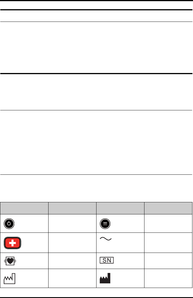
Symbol Description Symbol Description
Power On/Off key Main menu key
Nurse call key Alternating current (AC)
Defibrillation-proof Type
CF applied part
Serial number
Date of Manufacture Symbol for “MANUFAC-
TURER”
Equipment Symbols Safety
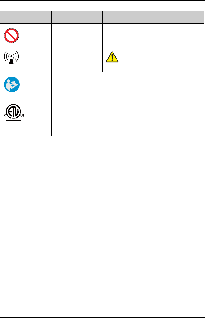
1 - 6 TMS60 Operator’s Manual
MR Unsafe – do not sub-
ject to magnetic reso-
nance imaging (MRI)
Protection against fluid
ingress
Interference may occur
in the vicinity of equip-
ment marked with this
symbol
General warning sign
Refer to instruction manual/booklet
The presence of this label indicates the machine was certified by ETL with the
statement:
Conforms to AAMI Std ES 60601-1, IEC 60601-1-6, IEC Std 60601-1-8, IEC Std 60601-
2-27, IEC Std 60601-2-49, ISO Std 80601-2-61
Certified to CSA Std C22.2 NO. 60601-1, NO. 60601-1-6, NO. 60601-1-8, NO.60601-2-
27, NO. 60601-2-49, NO.80601-2-61
Symbol Description Symbol Description
MR
IPX7
Intertek
3191955
ETL CLASSIFIED
NOTE
•Some symbols may not appear on your equipment.

TMS60 Operator’s Manual 2 - 1
2General Product Description
Intended Use .............................................................................................................2-2
Applied Parts .............................................................................................................2-2
Key Features...............................................................................................................2-2
System Components ..............................................................................................2-3
TD60 Physical View..................................................................................................2-3
Antenna Array ...........................................................................................................2-5
Telemetry Receiver (RC60)....................................................................................2-5
Touch Screen Display..............................................................................................2-5

Intended Use General Product Description
2 - 2 TMS60 Operator’s Manual
2.1 Intended Use
The TMS60 transmitter is intended for use on Adult and Pediatric patients to monitor
ECG and SpO2 physiological data. The physiological data can be reviewed locally on the
display of the transmitter. The CentralStation will support ECG, Heart Rate, SpO2, Pulse
Rate, Arrhythmia analysis, QT monitoring, and ST Segment Analysis for the TMS60.
It must be operated by trained medical personnel in hospitals or medical institutions.
2.2 Applied Parts
The equipment has the following applied parts:
■ECG leadwires
■SpO2 cables
■SpO2 sensors
2.3 Key Features
■3.5" color PTC touch screen display is easy for clinicians to use.
■Small, portable, and lightweight for patients to wear.
■Supports 3/5 lead ECG.
■Supports Masimo and Nonin SpO2 modules.
■Communication to the CS utilizes the protected WMTS 608-614 band.
■Displays the battery status and supports the multiple levels of battery alarms.
■Displays Heart Rate (HR) and SpO2 parameters, ECG and SpO2 waveforms.
■Battery options of two AA, three AA, or lithium-ion battery pack are available.
WARNING
•Only skilled/trained clinical professionals should operate this equip-
ment.
•The equipment is not designed for monitoring critically ill patients.
•If the accuracy of any value displayed at the CS or Telemetry transmitter
(TD60) is questionable, determine the patient’s vital signs by alternative
means and verify that the TMS is working correctly.
•The system transmits the data through the wireless connection. There
might be a risk of data loss.
General Product Description System Components
TMS60 Operator’s Manual 2 - 3
■Display supports Parameter auto-sizing.
2.4 System Components
The telemetry monitoring system (TMS60) includes the following components:
■Telemetry transmitter (TD60)
■Telemetry antenna array
■Telemetry receiver (RC60)
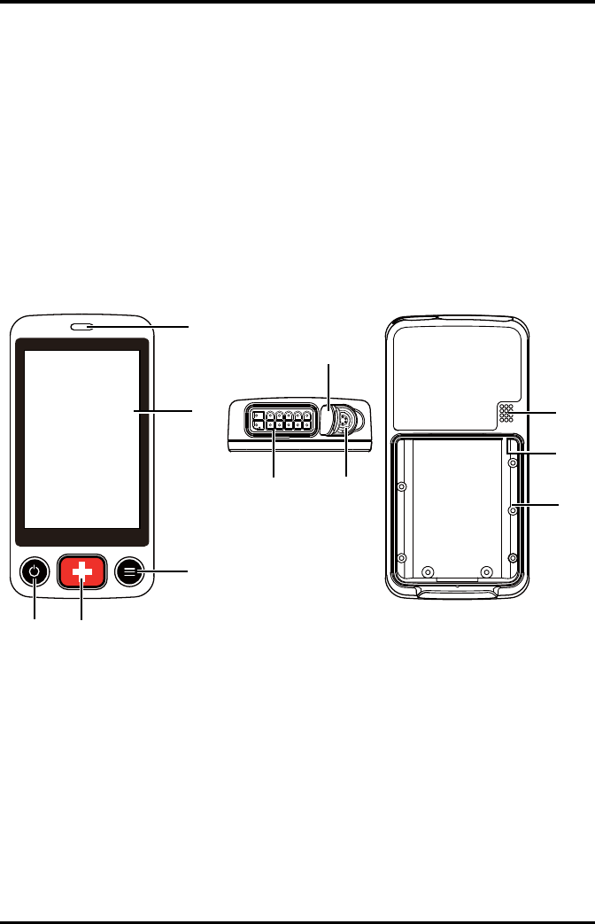
2.5 TD60 Physical View
1. Display Activation (Power On/Off) key
When the TD60 is powered off
◆Pressing this key will turn the TD60 on.
When the TD60 is powered on
◆If the screen display is on, pressing this key will turn the display off.
◆If the screen display is off, pressing this key will turn the display on.
◆Press and hold this key for two seconds to display the power off confirma-
tion menu.
5
4
3
12
68
11
7
9
10

TD60 Physical View General Product Description
2 - 4 TMS60 Operator’s Manual
2. Nurse Call key
Pressing this key will send a nurse call request to the CS. The alarm light/indicator
will illuminate cyan, and a “Nurse Call Initiated” message will display in the mes-
sage area if the display is on.
3. Main Menu key
◆Pressing this key when on the main screen will open the main menu.
◆Pressing this key when a menu is open will return to the main screen.
◆Pressing this key when the display is off will turn the display on.
? Pressing this key when the screen lock mode is configured for View Only will
display the [Screen Locked] menu.
4. Display
Touch screen display for viewing patient information and adjusting patient set-
tings.
5. Alarm light/indicator
Flashes in different color and frequency corresponding to the alarm level.
6. ECG connector
ECG lead connector.
7. SpO2 cap
Covers SpO2 connector when SpO2 is not in use.
8. SpO2 connector
Connects the SpO2 module.
9. Speaker
10. USB connector
It is only available for authorized service personnel.
11. Battery compartment
Contains the lithium-ion battery pack or AA battery tray.

General Product Description Antenna Array
TMS60 Operator’s Manual 2 - 5
2.6 Antenna Array
The antenna array must be installed and configured by Mindray authorized personnel.
For more details about the antenna array installation, calibration, and validation, refer to
the Telemetry Monitoring System Installation Guide (P/N 046-007624-00).
2.7 Telemetry Receiver (RC60)
The RC60 receives the data from the TD60 via the antenna array, and sends the data to
the CS for analysis and display.
For details about the general wireless communication problems, refer to "General Prob-
lems" on page 12 - 2.
For details about the frequency allocation and receiver connection, refer to the Teleme-
try Monitoring System Installation Guide (P/N 046-007624-00).
For details about the RC60, refer to the TMS60 Service Manual (P/N 046-007057-00).
2.8 Touch Screen Display
Move your finger on the touch screen display to operate the TD60. For details about the
supported touch gestures, refer to "Understanding the Screen Display Orientation" on
page 3 - 10.
WARNING
•Authorized Mindray personnel are required to confirm the coverage
area of the antenna array in the following situations:
◆When the antenna array is initially installed.
◆When the antenna array is modified.
◆When the building construction is modified.
WARNING
•Do not operate the touch screen with water on the hand.
Touch Screen Display General Product Description
2 - 6 TMS60 Operator’s Manual
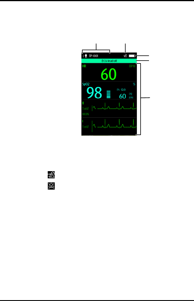
2.8.1 Display Screen
The main screen displays patient parameters and waveforms. A typical display screen is
shown below.
1. Patient information area
This area shows the patient information such as patient category, device name,
and department. Tapping this area displays the [Patient Info] menu.
2. Alarm symbols
◆ indicates that the alarm system is reset.
◆ indicates that the technical alarm audio is turned off.
3. Battery symbol
This symbol indicates the battery charge status. Refer to "Checking the Battery
Charge Status" on page 11 - 4 for details. Tapping the battery symbol opens the
[System Info] menu to the battery section.
4. Message area
This area shows technical alarm messages and informational messages, where
there are multiple messages, the messages scroll.
5. Patient data area
This user configurable area can display parameter/waveform data. The parameter/
waveform is labeled in the upper left corner. You may also tap this area to display
the Setup menu for the corresponding parameter/waveform.
For details about the touch screen operations, refer to "Basic Operations" on page 3 - 9.
12
3
4
5
General Product Description Touch Screen Display
TMS60 Operator’s Manual 2 - 7
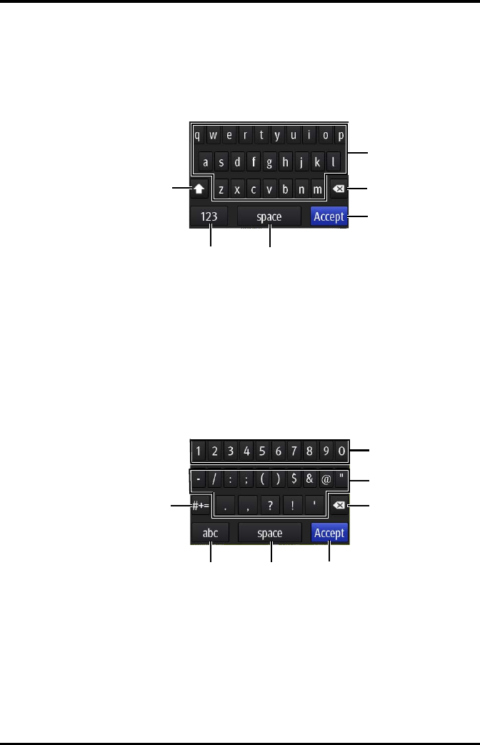
2.8.2 On-Screen Keyboard
The TD60 uses an on-screen keyboard to enter alphanumeric information, such as the
device name and passwords.
2.8.2.1 Alphabetic Keyboard
1. Alphabetic buttons: tap to input the desired alphabetic text.
2. Delete button: tap to erase the text to the left of the cursor.
3. Accept button: tap to save the settings and exit the keyboard.
4. Space button: tap to input a space.
5. Numeric switch button: tap to switch to the numeric layout.
6. Case shift button: tap to switch the case of the letter.
This switch is active for one character entry.
2.8.2.2 Numeric Keyboard
1. Numeric buttons: tap to input the desired numbers.
2. Punctuation buttons: tap to input the desired punctuation mark or symbol.
3. Delete button: tap to erase the text to the left of the cursor.
4. Accept button: tap to save the settings and exit the keyboard.
5. Space button: tap to input a space.
6. Alphabetic switch button: tap to switch to the alphabetic layout.
1
2
3
4
5
6
1
2
3
4
5
6
7

Touch Screen Display General Product Description
2 - 8 TMS60 Operator’s Manual
7. More punctuation buttons: tap to display the punctuation keyboard, as shown
below.

TMS60 Operator’s Manual 3 - 1
3Getting Started
Unpacking and Checking......................................................................................3-2
Environmental Requirements .............................................................................3-3
Connecting the ECG Leadwire ............................................................................3-4
Installing the Batteries ...........................................................................................3-5
Powering On the Unit.............................................................................................3-8
Understanding Touch Gestures..........................................................................3-9
Basic Operations.......................................................................................................3-9
Using the Pouch .......................................................................................................3-14

Unpacking and Checking Getting Started
3 - 2 TMS60 Operator’s Manual
3.1 Unpacking and Checking
Before unpacking, examine the packing case carefully for signs of damage. If any dam-
age is detected, contact the carrier or Mindray.
If the packing case is intact, open the package and remove the device and accessories
carefully. Check all materials against the packing list and check for any mechanical dam-
age. Contact Mindray in case of any problem.
WARNING
•The telemetry monitoring system (TMS60) shall be installed by Mindray
authorized personnel.
•The software equipment copyright is solely owned by Mindray. No orga-
nization or individual shall resort to altering, copying, or exchanging it
or to any other infringement on it in any form or by any means without
due permission.
•Connect only approved devices to this system. Devices connected to the
equipment must meet the requirements of the applicable IEC standards
(e.g. IEC 60950 safety standards for information technology equipment
and IEC 60601-1 safety standards for medical electrical equipment). The
system configuration must meet the requirements of the IEC 60601-1
medical electrical systems standard. Any personnel who connect devices
to the equipment’s signal input/output port is responsible for providing
evidence that the safety certification of the devices has been performed
in accordance to the IEC 60601-1. If you have any questions, please con-
tact Mindray.
•If it is not evident from the equipment specifications whether a particu-
lar combination with other devices is hazardous, for example, due to
summation of leakage currents, please consult the manufacturers or
else an expert in the field, to ensure the necessary safety of patients and
all devices concerned will not be impaired by the proposed combina-
tion.
•Contact Mindray to relocate the TMS60.
•Only Mindray authorized personnel can update the TMS60.

Getting Started Environmental Requirements
TMS60 Operator’s Manual 3 - 3
3.2 Environmental Requirements
The operating environment of the system must meet the requirements specified in this
manual.
The equipment operating environment should be reasonably free from noises, vibration,
dust, corrosive, flammable and explosive substances.
When the device is moved from one place to another, condensation may occur as a
result of temperature or humidity difference. In this case, never start the system before
the condensation disappears.
WARNING
•Before use, please verify whether the packages are intact, especially the
packages of single use accessories. In case of any damage, do not apply
it to patients.
•Do not let the display directly touch the patient when the display is on.
NOTE
•Save the packing case and packaging material as they can be used if the
device must be reshipped.
WARNING
•Make sure that the device operating environment meets the specifica-
tions. Otherwise unexpected consequences, e.g. damage to the device,
could result.
NOTE
•The system transmits data through a wireless connection. External radio
frequency interference may result in occasionally data dropout. Contact
Mindray for any questions regarding the electromagnetic environment.
Connecting the ECG Leadwire Getting Started
3 - 4 TMS60 Operator’s Manual
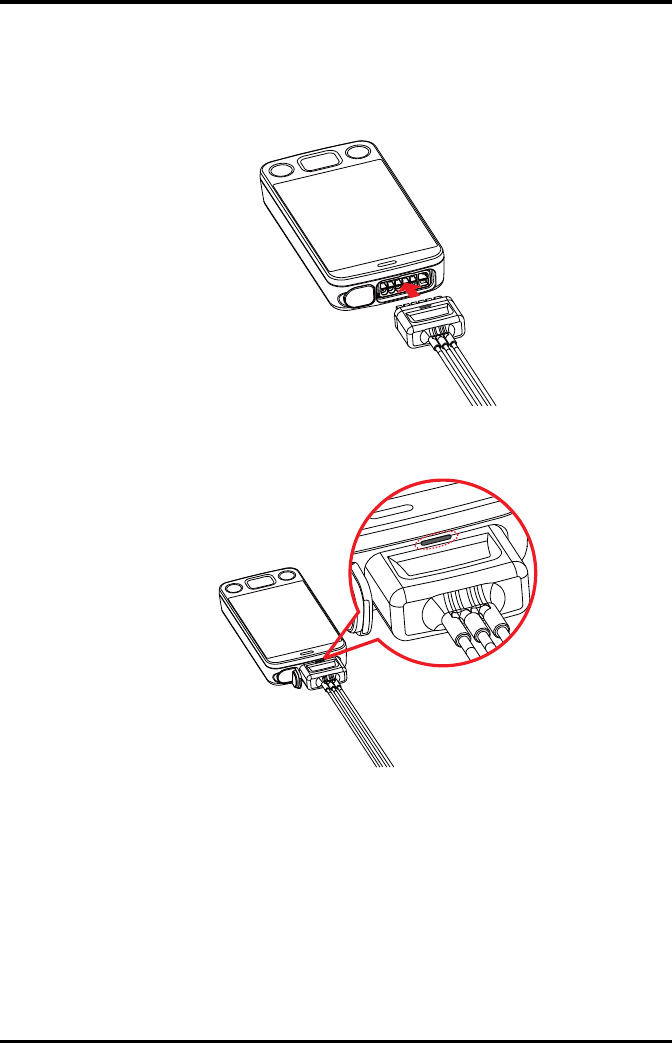
3.3 Connecting the ECG Leadwire
1. Align the ECG leadwire plug with the ECG connector as indicated by the arrow in
the following figure.
2. Insert the ECG leadwire plug into the ECG connector as shown in the enlarged fig-
ure below.

Getting Started Installing the Batteries
TMS60 Operator’s Manual 3 - 5
3.4 Installing the Batteries
You can use two AA, three AA batteries or a lithium-ion rechargeable battery pack to run
the TD60. The runtime is dependent on the battery solution you chose. A lithium-ion
battery pack will provide the longest runtime. For details about the recommended AA
batteries, refer to "Miscellaneous" on page 15 - 5.
WARNING
•Insert the ECG lead set into the ECG connector. The following perfor-
mance may be affected by a weak connection:
◆ECG signal quality
◆Wireless signal strength
◆Water resistance
•Do not use the ECG leadwire to move or lift the TD60. This may cause the
device to fall, which may damage the equipment or injure the patient.
NOTE
•ECG leadwires are used as the antenna for the TD60. To ensure good
radio performance, always connect the ECG leadwires to the ECG con-
nector while monitoring the patient.
•Insert the SpO2 cap in the SpO2 connector when SpO2 is not in use.
NOTE
•Always keep the battery compartment dry.
•Never use brute force to install the lithium-ion battery pack or AA bat-
tery tray. Otherwise the waterproof ring surrounding the battery frame
edge may be broken to affect the waterproof performance.
Installing the Batteries Getting Started
3 - 6 TMS60 Operator’s Manual
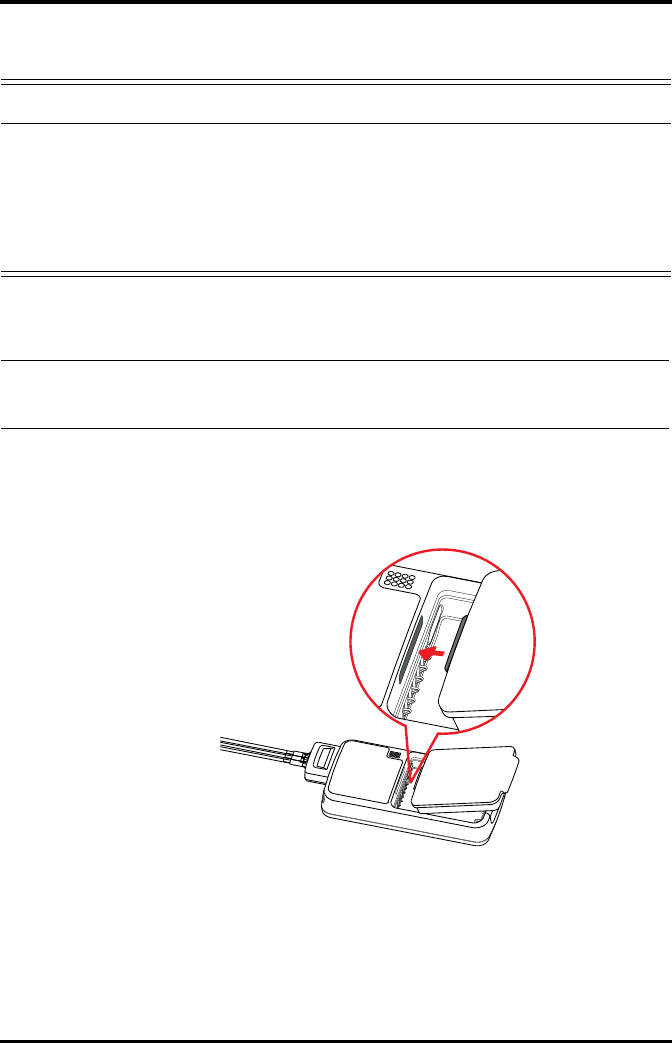
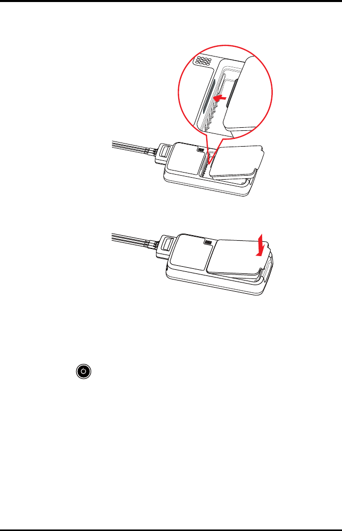
3.4.1 Installing the Lithium-ion Rechargeable Battery
1. Make sure the battery compartment is empty.
2. Align the hook on the upper part of the lithium-ion battery pack with the slot on
the battery compartment, as indicated by the enlarged figure below.
WARNING
•Only use specified lithium-ion rechargeable batteries. Use of other lith-
ium-ion batteries will adversely affect the batteries:
◆Level reporting
◆Low battery alarms
◆Life performance
NOTE
•The lithium-ion rechargeable battery should be fully charged prior to
first use.
Getting Started Installing the Batteries
TMS60 Operator’s Manual 3 - 7
3. Press down the battery pack until it is installed firmly, as indicated by the arrow in
the following figure.
The TD60 is automatically powered on after the battery is installed.
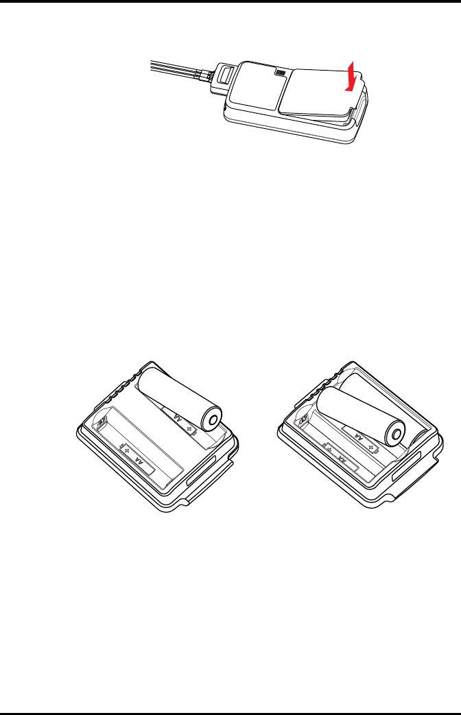
3.4.2 Installing the AA Batteries
There are two types of AA battery trays, which are used for holding AA batteries:
■TP-2AA battery tray can hold two AA batteries.
■TP-3AA battery tray can hold three AA batteries.
To install the AA batteries:
1. Make sure the battery compartment is empty.
2. Insert two or three 1.5V alkaline AA batteries according to the diagram in the bot-
tom of the battery tray as shown in the images below.
Installing two AA batteries Installing three AA batteries
Powering On the Unit Getting Started
3 - 8 TMS60 Operator’s Manual
3. Align the hook on the upper part of the battery tray with the slot on the battery
compartment, as indicated by the enlarged part in the following figure.
4. Press down the battery tray until it closes firmly, as indicated by the arrow in the
following figure.
The TD60 is automatically powered on after the batteries are installed.
3.5 Powering On the Unit
Press the key to turn on the TD60. The cyan alarm light will momentarily turn on to
indicate that the device is starting. The TD60 performs a self-test during startup. The
device sounds a beep, and the alarm light serially turns red, yellow, cyan, and then off.
This indicates that the alarm system functions correctly.
Upon powering up, there are two situations:
■If the TD60 is turned on at first time, the device will request you to configure first
time startup. Refer to the TMS60 Service Manual (P/N 046-007057-00) for details.
■If the TD60 is turned on next time, the device will prompt whether it is a new
patient. Select [Yes] or [No] as desired. If the device is a lock mode, a passcode is
required.
Getting Started Understanding Touch Gestures
TMS60 Operator’s Manual 3 - 9
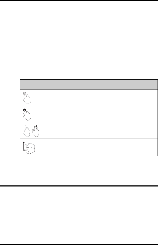
3.6 Understanding Touch Gestures
Before using the TD60, understand the supported touch screen gestures:
3.7 Basic Operations
This section describes the basic operations for the TD60.
WARNING
•Check that visual and auditory alarm signals are presented correctly
when the equipment is powered on. Do not use the equipment for any
monitoring procedure on a patient if you suspect the equipment is not
working properly or if the equipment is mechanically damaged. Contact
your service personnel or Mindray.
Gesture Description
Tap Briefly touch the surface with your fingertip to select a target.
Press and hold Touch the surface for extended period of time.
Drag Move your fingertip over the surface without losing contact.
Swipe Quickly brush the surface with your fingertip.
WARNING
•Patients should be instructed not to interact with the display of the
device and to not open the battery compartment while the TD60 is in
use.
Basic Operations Getting Started
3 - 10 TMS60 Operator’s Manual
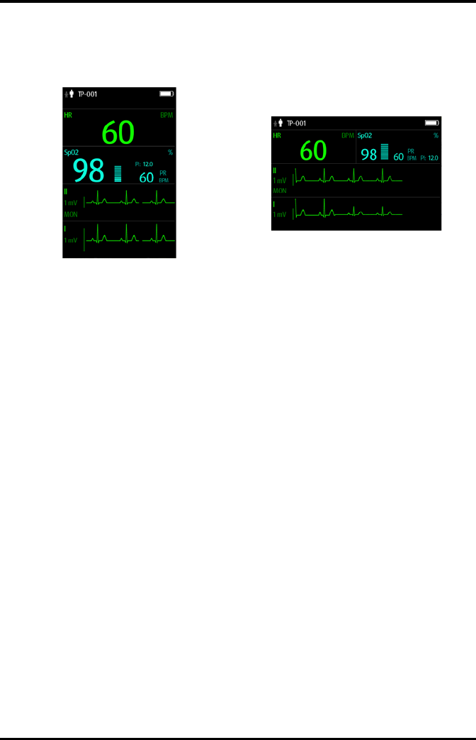
3.7.1 Understanding the Screen Display Orientation
The TD60 supports both the portrait and landscape display orientations.
■Portrait: both digital and waveform tiles take up the entire width of the screen.
■Landscape: the digital tile takes up one half of the width of the screen; the
waveform tile takes up the entire width of the screen.
3.7.2 Browsing the Screen Display
To scroll through the waveforms/parameters, swipe your finger up or down on the
screen.
3.7.3 Switching the Screen Display Orientation
1. Swipe your finger down from the top of the main screen to display the drop-down
menu.
2. Tap the desired option to switch the screen display orientation.
For example, to switch from portrait display to landscape display:
1. Swipe your finger down from the top of the main screen to display the drop-down
menu.
2. Tap [Landscape] to switch to landscape display.
3.7.4 Flipping the Landscape Display
1. Swipe your finger down from the top of the main screen to display the drop-down
menu.
2. Tap [Flip Display] to horizontally flip the landscape display.
Example of portrait display Example of landscape display
Getting Started Basic Operations
TMS60 Operator’s Manual 3 - 11
3.7.5 Displaying the Quick Keys Area
Swipe your finger up from the bottom of the main screen to display the quick keys area.
The following table lists the six default quick keys:
You can customize the most frequently used functions to the quick keys. For details
about setting the quick keys, refer to "Quick Keys Menu" on page 10 - 5.
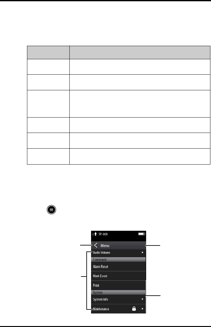
3.7.6 Entering the Main Menu
Press the key to enter the main menu.
The main menu allows access to most of the system functions and settings.
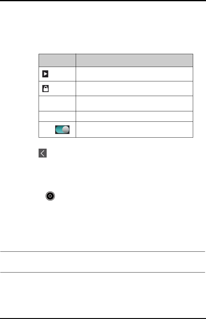
Quick keys Description
Discharge Patient Tap the button to enter the [Discharge Patient] menu. Refer to
"Discharging the Patient" on page 5 - 4 for details.
Standby Tap the button to enter the [Standby] menu. Refer to "Placing a Device
in Standby" on page 5 - 3 for details.
Change Lead Tap the button to change the current first ECG lead waveform to the next
ECG lead waveform that is available in sequential order.
For example, if the current first ECG lead waveform is I lead, tap the
button, the I lead waveform is changed to II lead waveform.
Print Tap the button to notify the central station (CS) to start real-time print.
The “Print Initiated” message displays on the screen.
Manual Event Tap the button to notify the CS to save the event to the event database.
The “Manual Event” message displays on the screen.
Alarm Reset Tap the button to reset the alarm system. Refer to "Resetting the Alarms"
on page 6 - 5 for details.
41
2
3
Basic Operations Getting Started
3 - 12 TMS60 Operator’s Manual
All menus contain the following parts:
1. Heading: displays the current menu title.
2. Scroll bar: indicates the current scroll position within the menu.
3. Main body: contains menus, buttons, and other controls to configure and operate
the device.
4. exits the current menu and return to the previous menu or the main screen.
3.7.7 Turning the Display Off
You can manually turn the display off, or let the display automatically turn off based on
the configured timeout.
Press the key to manually turn the display off.
If the touch screen is not touched for the configured Display Auto Off time, then the
screen will turn off after the configured Display Auto Off time.
For details about configuring the time for Display Auto Off, refer to "Configuring the
General Menu" on page 10 - 2.
Controls Description
Accesses a submenu to reveal more options or information.
Indicates that a password is required for access.
Submenus Contains more operations or information related to the
corresponding menu.
Buttons Provides an option to operate a function.
Switch
Drag to right to enable the switch; drag to left to disable the
switch.
NOTE
•While the display is off, the TD60 enters the power saving mode, and
does not provide audio and visual alarms.

Getting Started Basic Operations
TMS60 Operator’s Manual 3 - 13
3.7.8 Turning the Display On
If the screen is off, press the or key to turn the display on.
3.7.9 Unlocking the Screen
If you set the screen lock, you need to input the correct passcode to unlock the screen
after the display turns off.
To unlock the screen in Locked mode:
1. If the screen is off, press the or key to turn the display on and access the
[Screen Locked] menu.
2. Input the passcode to unlock the screen.
Once the passcode is entered the screen is temporarily unlocked. If the is
pressed or the device times out, the screen will lock again and a passcode must be
entered.
To unlock the screen in View Only mode:
1. If the screen is off, press the or key to turn the display on.
2. Press the key to display the [Screen Locked] menu.
3. Input the passcode to unlock the screen.
Once the passcode is entered the screen is temporarily unlocked. If the is
pressed or the device times out, the screen will lock again and a passcode must be
entered.
For details about setting the screen lock, refer to "Screen Lock Menu" on page 10 - 8.
3.7.10 Acknowledging the Nurse Call
To acknowledge the triggered nurse call, tap [Attendant Present] in the main menu.
The “Nurse Call Cancelled” message will display in the message area.
For details about how to trigger a nurse call, refer to "TD60 Physical View" on page 2 - 3.
CAUTION
•Do not let the display directly touch the patient when the display is on.
Using the Pouch Getting Started
3 - 14 TMS60 Operator’s Manual
3.8 Using the Pouch
The TD60 is not intended for direct contact with the patient’s skin. During normal use,
the TD60 could be worn over clothing, in a pocket, or in a pouch. The waterproof pouch
with clear front is an appropriate means for holding the TD60. Both disposable and reus-
able pouches specified in this manual can be used for the TD60. For details about the
pouch, refer to "Miscellaneous" on page 15 - 5.
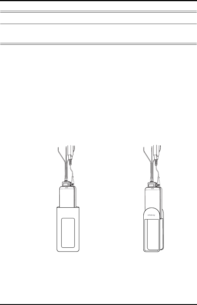
3.8.1 Securing the Pouch
To secure the pouch:
1. Place the TD60 into the pouch with the ECG leadwires and the SpO2 sensor cable,
if used, exiting from the pouch opening, as shown in the following figures.
2. Pinch the snap-fastener to close the pouch.
3. Secure the pouch on the patient with ties around the patient’s shoulder and under
the arm, as shown in the following figure.
WARNING
•Do not only rely on the nurse call function, the medical personnel
should also pay close attention to the patient’s condition.
For disposable pouch For reusable pouch

Getting Started Using the Pouch
TMS60 Operator’s Manual 3 - 15
Wearing the disposable pouch Wearing the reusable pouch
WARNING
•While using a pouch with the TD60 on the patient, consider the patient’s
condition. Be careful about the placement of the straps, as the straps
could present a strangulation hazard.
NOTE
•The pouch is used only for the TD60. The pouch cannot be used for car-
rying other personal devices, such as a mobile phone.

Using the Pouch Getting Started
3 - 16 TMS60 Operator’s Manual
This page intentionally left blank.

TMS60 Operator’s Manual 4 - 1
4User Configurations
Introduction...............................................................................................................4-2
Configuring the Display.........................................................................................4-2
Configuring the Audio Volume...........................................................................4-5

Introduction User Configurations
4 - 2 TMS60 Operator’s Manual
4.1 Introduction
This chapter describes the configurations available for users to do, such as configuring
the Display Setup, and Audio Volume.
4.2 Configuring the Display
You can configure the display by setting the display layout, display orientation, and
screen brightness.
In the main menu, tap [Display Setup] to enter the [Display Setup] menu.
4.2.1 Setting the Default Display Orientation
For details about the display orientation, refer to "Understanding the Screen Display
Orientation" on page 3 - 10.
1. In the [Setup] section of the [Display Setup] menu, tap [Default Orientation].
Two buttons display: [Portrait] and [Landscape].
2. Tap a button to set the default orientation.
The selected orientation displays to the right of [Default Orientation].
3. Restart the TD60 to apply the setting.
4.2.2 Understanding Portrait Orientation Display Rules
In portrait orientation, both digital and waveform areas take up the entire width of the
screen. Therefore, these parameters will be displayed in the exact order of the [Display
Setup] menu, provided the sensor is attached and monitoring data.
4.2.3 Setting the Portrait Display
1. In the [Portrait] section of the [Display Setup] menu, tap [Rows].
Three options display: [2], [3], and [4].
2. Tap an option to set the row numbers.
The selected option displays to the right of [Rows].
3. Tap [Portrait Order] to enter the [Portrait Order] menu.
4. Tap a parameter or waveform to select it.
The icon displays to the right of the selected parameter or waveform.
5. Drag the selected parameter or waveform to the desired position, and then release
it.
6. Repeat steps 4 and 5 until the desired order is configured.
7. Tap the icon to exit the [Portrait Order] menu.

User Configurations Configuring the Display
TMS60 Operator’s Manual 4 - 3
4.2.4 Understanding Landscape Orientation Display Rules
In landscape orientation, waveform areas take up the entire width of the screen. Digital
areas only take up one half of the width of the screen. The following rules define how the
tiles will be laid out:
1. The areas shall be displayed in the order of the [Display Setup] menu except the
digital area locations shall be optimized to reduce blank tiles.
2. A waveform area always takes up the entire width of the screen.
3. A digital area always takes up one half of the width of the screen. Therefore, a row
with a digital tile in it shall be split into two half tiles.
4. A digital area shall not be the only parameter in a row unless an odd number of
digital areas exist. In this case, the last digital parameter area shall have one tile on
the left side and the right half will be blank.
5. Digital areas shall be paired with the next available digital area to satisfy rule 4.
This means that a digital area may be moved ahead of a waveform area if a half of a
row needs to be filled.
For example, if the landscape display rows is set to [3] and the parameter order is as fol-
lows:
HR
ECG I
ECG II
ECG III
ECG aVR
ECG aVF
ECG aVL
ECG V
SpO2
PLETH
The landscape layout displays as follows:
HR* SpO2
ECG I
ECG II
ECG III
ECG aVR
ECG aVF
ECG aVL
ECG V
PLETH
*Bold is displaying on screen; non-
bold data need to be scrolled to.

Configuring the Display User Configurations
4 - 4 TMS60 Operator’s Manual
4.2.5 Setting the Landscape Display
1. In the [Landscape] section of the [Display Setup] menu, tap [Rows].
Three options display: [2], [3], and [4].
2. Tap an option to set the row numbers.
The selected option displays to the right of [Rows].
3. Tap [Landscape Order] to enter the [Landscape Order] menu.
4. Tap a parameter or waveform option to select it.
The icon displays to the right side of the selected parameter or waveform.
5. Drag the selected parameter or waveform to the desired position, and then release
it.
6. Repeat steps 4 and 5 until the desired order is configured.
7. Tap the icon to exit the [Landscape Order] menu.
4.2.6 Setting the Display Brightness
1. In the [Setup] section of the [Display Setup] menu, tap [Display Brightness].
The [Display Brightness] menu displays.
2. Drag the slider to left or right to adjust the brightness.
3. Tap the icon to exit the [Display Brightness] menu.

User Configurations Configuring the Audio Volume
TMS60 Operator’s Manual 4 - 5
4.3 Configuring the Audio Volume
You can independently set the technical alarm volume, touch screen click, and systole
beep volume. The method for setting the three volumes are the same.
To change the volume settings:
1. In the main menu, tap [Audio Volume].
2. In the [Technical Alarm], [Touch Screen Click], or [Systole Beep] section, drag
the slider to the left or right to adjust the volume.
3. Tap the icon to exit the [Audio Volume] menu.
NOTE
•The icon indicates that the audio volume is turned off.
•The minimum value for the technical alarm volume depends on the min-
imum technical alarm volume, refer to "Configuring the Alarms Menu" on
page 10 - 3 for details.

Configuring the Audio Volume User Configurations
4 - 6 TMS60 Operator’s Manual
This page intentionally left blank.

TMS60 Operator’s Manual 5 - 1
5Patient Management
Introduction...............................................................................................................5-2
Admitting a Patient.................................................................................................5-2
Changing the Patient Category..........................................................................5-2
Placing a Device in Standby.................................................................................5-3
Resume Monitoring ................................................................................................5-4
Discharging the Patient.........................................................................................5-4

Introduction Patient Management
5 - 2 TMS60 Operator’s Manual
5.1 Introduction
The chapter describes how to admit a patient, change the patient size, enter and exit the
Standby mode, and discharge the patient.
5.2 Admitting a Patient
When admitting a TM80 for the first time, the device must be admitted to the system
through the CS. For details about admitting a patient through the CS, refer to the
BeneVision Central Station Operator’s Manual (P/N 046-005011-00).
After first admitting the device to the CS, you can directly admit the new patient at the
TD60 by discharging the current patient, and then pressing the key to admit a new
patient. Refer to "Discharging the Patient" on page 5 - 4 for details.
5.3 Changing the Patient Category
1. In the main menu, tap [Patient Info].
2. In the [Patient Info] menu, tap [Patient Category] to select the desired patient
category.
The screen displays the “Are you sure you want to change patient category?” mes-
sage.
3. Select [Yes ] to confirm that the patient category is changed.
The selected patient category displays to the right of [Patient Category].
4. Tap the icon to exit the [Patient Info] menu.
NOTE
•Ensure the patient category selection is appropriate for the patient
before monitoring begins.
NOTE
•The patient category can only be changed at the TD60.
•Adjusting patient category restores the TD60 to the default (preset) set-
tings but does not clear patient information or data.

Patient Management Placing a Device in Standby
TMS60 Operator’s Manual 5 - 3
5.4 Placing a Device in Standby
To enter the Standby mode:
1. In the main menu, tap [Standby].
2. In the [Standby] confirmation menu, select [Yes ].
Placing a device into Standby mode does the following:
■Suspends patient monitoring
■Alarms are suspended
■Displays [Standby] on the screen.
■The screen display automatically turns off after the device enters the Standby
mode for 30 seconds.
NOTE
•When the device is connected to the CS, the patient category at the CS is
updated if the patient category is changed at the TD60. Refer to the
BeneVision Central Station Operator’s Manual (P/N 046-005011-00) for
details.
NOTE
•When connected to the CS, and a device enters or exits Standby mode,
the CS is also notified to enter or exit Standby mode. Refer to the
BeneVision Central Station Operator’s Manual (P/N 046-005011-00) for
details.
NOTE
•When connected to the CS, and a device enters or exits Standby mode,
the CS is also notified to enter or exit Standby mode.

Resume Monitoring Patient Management
5 - 4 TMS60 Operator’s Manual
5.5 Resume Monitoring
Press the key to exit Standby mode.
Resume monitoring:
■Restores patient’s settings, resumes alarm notification on the TD60 and the CS.
■Alarm system is activated.
■The TD60 notifies the CS of returning to the Monitoring mode.
5.6 Discharging the Patient
Discharging the patient will stop monitoring, clear patient information, and restore
default (preset) settings on the TD60. When a new patient is admitted, the user configu-
ration will be applied. If the user configuration has not been saved, the factory default
configuration will be applied.
A patient can be discharged by selecting the [Discharge Patient] menu, or restarting
the TD60 and selecting that a new patient is on the TD60.
5.6.1 Selecting the [Discharge Patient] menu
1. In the main menu, tap [Discharge Patient].
2. In the [Discharge Patient] confirmation menu, select [Yes ].
◆The patient is discharged from both the TD60 and the CS.
◆The patient’s configuration is cleared and the configuration is restored to the
saved user configuration or factory default configuration.
◆The patient will be added to the [Discharged Pat.] list at the CS.
3. Press the key to admit a new patient.
NOTE
•Discharging the patient on the TD60 discharges the patient from the CS.
Refer to the BeneVision Central Station Operator’s Manual (P/N 046-
005011-00) for details.

Patient Management Discharging the Patient
TMS60 Operator’s Manual 5 - 5
5.6.2 Restarting the TD60
1. If the TD60 is powered off, press the key to turn on the TD60.
The device will prompt as to whether this is a new patient or not.
2. Select [Yes ] if this is a new patient. Select [Ye s] when asked to confirm that the dis-
charge should begin. Refer to "Selecting the [Discharge Patient] menu" on page 5
- 4 for details on the discharge process.

Discharging the Patient Patient Management
5 - 6 TMS60 Operator’s Manual
This page intentionally left blank.

TMS60 Operator’s Manual 6 - 1
6Alarms
Introduction...............................................................................................................6-2
Alarm Categories......................................................................................................6-2
Alarm Levels...............................................................................................................6-2
Alarm Indicators.......................................................................................................6-3
Configuring the Alarms .........................................................................................6-5
Resetting the Alarms ..............................................................................................6-5

Introduction Alarms
6 - 2 TMS60 Operator’s Manual
6.1 Introduction
Alarms, triggered by technical problems, are visually and audibly indicated to the user
when the display is on.
The TD60 provides a subset of the technical alarms, this chapter describes the technical
alarms presented at the TD60 only. For details regarding full list of the technical alarms
as well as the physiological alarms displayed at the central station (CS), refer to
"Physiological Alarms" on page 9 - 2.
6.2 Alarm Categories
The TD60 alarm system only supports technical alarms, see the BeneVision Central
Station Operator’s Manual (P/N 046-007960-00) for details on physiological alarms.
Technical alarms are triggered by system status, patient status, a device malfunction or a
patient data distortion due to improper operation or mechanical problems. Technical
alarms are available both at the TD60 and the CS.
In addition to the technical alarms, the TD60 also displays informational message to
inform the user of patient/system status. The TD60 will display informational messages
in the message area at the top of the display.
6.3 Alarm Levels
The alarms can be classified into three severity levels: high level, medium level and low
level.
WARNING
•The reception failure of alarm signals may occur in the distributed alarm
system.
Alarm Levels Technical alarms
High level Indicates a severe device malfunction or an improper operation, which could
make it possible that the monitor cannot detect critical patient status and
thus threaten the patient’s life, such as low battery.
Medium level Indicates a device malfunction or an improper operation, which may not
threaten the patient’s life but may compromise the monitoring of vital physi-
ological parameters.
Low level Indicates a device malfunction or an improper operation, which may compro-
mise a certain monitoring function but will not threaten the patient’s life.

Alarms Alarm Indicators
TMS60 Operator’s Manual 6 - 3
6.4 Alarm Indicators
When a technical alarm occurs, the TD60 notifies the user through visual or audible
alarm indications.
■Alarm light
■Audible alarm tones
■Alarm message
6.4.1 Alarm Light
If a technical alarm occurs, the alarm light on the TD60 flashes. The color and flashing
frequency correspond to the alarm level as follows:
6.4.2 Alarm Tones
The TD60 has three alarm tone configurations: ISO, Mode 1 and Mode 2. For each
configuration, the alarm tones enunciate the alarm levels as follows:
NOTE
•When the TD60 display is off, the user must activate the screen to view
any local alarms.
■High level alarms: the lamp quickly flashes red.
■Medium level alarms: the lamp slowly flashes yellow.
■Low level alarms: the lamp lights cyan without flashing.
■ISO pattern:
◆High level alarms:
◆Medium level alarms:
◆Low level alarms:
triple+double+triple+double beep
triple beep
single beep
■Mode 1:
◆High level alarms:
◆Medium level alarms:
◆Low level alarms:
high-pitched single beep
double beep
low-pitched single beep
■Mode 2:
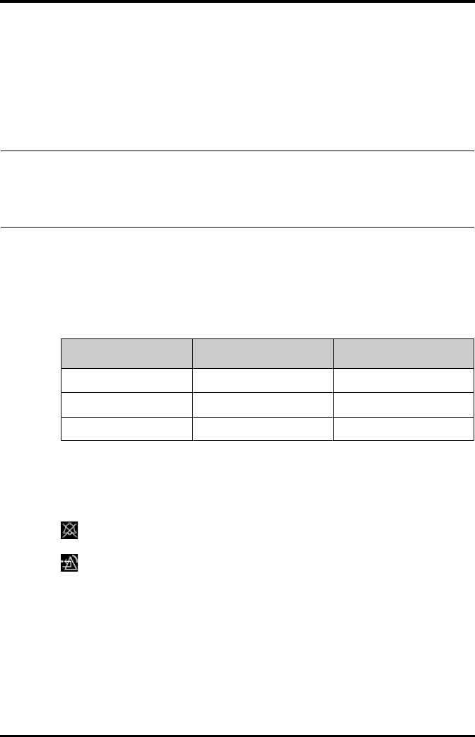
Alarm Indicators Alarms
6 - 4 TMS60 Operator’s Manual
6.4.3 Alarm Messages
When a technical alarm occurs on the TD60 screen, the alarm message appears in the
message area. The background color of the alarm message and the asterisk symbols (*)
before the alarm message are designed to indicate the alarm level.
6.4.4 Alarm Status Symbols
The TD60 still uses the following symbols indicating the alarm status:
: indicates the technical alarm audio is turned off.
: indicates the alarm system is reset.
◆High level alarms:
◆Medium level alarms:
◆Low level alarms:
high-pitched triple beep
double beep
low-pitched single beep
NOTE
•When multiple technical alarms of different levels occur simultaneously,
the TD60 selects the alarm of the highest level to light the alarm light
and sound alarms accordingly, while all the alarm messages scroll in the
message area on the top of the screen.
Alarms Background color Asterisk symbols (*)
High level alarms red ***
Medium level alarms yellow **
Low level alarms cyan *

Alarms Configuring the Alarms
TMS60 Operator’s Manual 6 - 5
6.5 Configuring the Alarms
■For details on configuring the technical alarm volume, refer to "Configuring the
Audio Volume" on page 4 - 5.
■For details on configuring the TD60 technical alarm settings, refer to "Configuring
the Alarms Menu" on page 10 - 3.
■For the CS alarm configurations, refer to the BeneVision Central Station Opera-
tor’s Manual (P/N 046-007960-00).
6.6 Resetting the Alarms
You can acknowledge the on-going alarms by resetting the alarms. After being reset the
alarm system can respond to a subsequent alarm condition.
When a technical alarm occurs, follow this procedure to reset the TD60 alarm system.
■Press the key to enter the main menu, and then tap [Alarm Reset] from the
[Commands] section.
OR
1. Swipe your finger up at the bottom of the main screen to display the quick keys
area.
2. Tap the [Alarm Reset] quick key to reset the alarm system.
When the alarm system is reset, depending upon the technical alarm there are several
ways the alarm system may respond as follows:
■The alarm sound will be silenced, the alarm light will continue to indicate the
alarm, a √ will appear before the alarm message. The symbol appears on the
top of the main screen.
■The technical alarm will be changed to the prompt message, it will not longer
make sound or be indicated by the alarm light.
■The technical alarms are cleared, there will be no alarm indications.
For details about the indications of technical alarms when the alarm system is reset, refer
to "Technical Alarm Messages at the TD60" on page 12 - 5.

Resetting the Alarms Alarms
6 - 6 TMS60 Operator’s Manual
This page intentionally left blank.

TMS60 Operator’s Manual 7 - 1
7Monitoring ECG
Introduction...............................................................................................................7-2
Safety............................................................................................................................7-2
Preparation for Monitoring ECG .........................................................................7-3
Changing the ECG Settings..................................................................................7-11
Understanding the ECG Display .........................................................................7-14

Introduction Monitoring ECG
7 - 2 TMS60 Operator’s Manual
7.1 Introduction
The chapter describes the ECG monitoring function of the TD60, including skin prepara-
tion and lead placement, ECG Setup, ECG Waveform, and Pacer.
The TD60 can obtain an ECG value by using a 3/5 lead ECG leadwires in conjunction with
the matching skin electrodes.
For details about CS configuration of the ECG parameters, QT analysis, ST analysis, and
Arrhythmia analysis, refer to Chapter 9 Monitoring with the TD60 at the CS.
7.2 Safety
WARNING
•Use manufacturer specified electrodes and lead wires.
•Make sure the conductive parts of electrodes and associated connectors
for applied parts, including the neutral electrode, do not contact any
other conductive parts including earth.
•Periodically inspect the electrode application site to ensure skin quality.
If the skin quality changes, replace the electrodes or change the applica-
tion site.
•Do not touch the patient or any device connected to the patient, includ-
ing the bed and gurney, during defibrillation. Otherwise serious injury
or death could result.
CAUTION
•Interference from a non-grounded instrument near the patient and elec-
tro-surgery interference can cause problems with the waveform.
NOTE
•After defibrillation, the waveform recovers within 10 seconds applied in
accordance with the manufacturer’s instructions for use.

Monitoring ECG Preparation for Monitoring ECG
TMS60 Operator’s Manual 7 - 3
7.3 Preparation for Monitoring ECG
7.3.1 Preparing the Patient’s Skin
Proper skin preparation is essential in obtaining an accurate ECG reading. Electrode sites
should be clean and dry and should provide a smooth flat surface. Incidental electrical
activity and inaccurate readings may arise from incorrect skin preparation.
The following procedure is recommended for secure electrode application:
1. Shave the chest hair from the electrode sites in a circular area with a diameter of 2
to 4 inches.
2. Use a dry gauze pad to remove excess skin oils, skin cells and residue from the
electrode sites. Never rub the skin until it is raw or bleeding.
7.3.2 Positioning the Electrodes
NOTE
•Prepare the electrode site with alcohol only if the skin is extremely
greasy. If alcohol is used as a drying agent, always allow the skin to dry
before placing the electrode on the skin.
NOTE
•Store electrodes at room temperature and open just prior to use.
•Avoid more than one type of electrode on a patient because of varia-
tions in electrical resistance.
•Avoid placing electrodes directly over bone prominences or over any
high activity movement areas such as shoulders or arms because muscle
motion produces electrical activity. If an electrode is placed over a large
muscle such as the pectorals, the device may detect this additional mus-
cle activity and could lead to false arrhythmia calls.
•Using a Transcutaneous Electrical Nerve Stimulator (TENS): Since a TENS
unit transmits electrical impulses, avoid placing ECG electrode near the
TENS electrodes. ECG electrodes may need to be repositioned and the
ECG lead viewed may need to be adjusted until the optimum ECG trac-
ing is obtained.

Preparation for Monitoring ECG Monitoring ECG
7 - 4 TMS60 Operator’s Manual
1. Peel the backing off of the electrode. Visually inspect the contact gel medium for
moistness. If the gel medium is not moist, do not use the electrode patch. Dry elec-
trode patches are not conductive.
2. Attach the electrode patch to the skin at the prepared site. Smooth the electrode
patch down in a circular motion to ensure proper skin contact. If using soft gel
electrodes, never push down directly over the contact gel medium as this may dis-
place the gel and cause monitoring artifact. If using hard gel electrodes, it is rec-
ommended that during application, the center of the electrode should be slightly
pressed onto the skin to ensure direct contact. Consult the electrode manufac-
turer’s instructions for specific use.
3. Secure the lead wires to the patient according to hospital practice.
NOTE
•To prevent evaporation of the contact gel medium, peel the backing off
of the electrode patch only when it is ready for use.
•If using the snap type lead wires, attach the electrode to the lead wire
before placing the electrode on the patient.
CAUTION
•Route leadwires neatly. Ensure leadwires are kept away from patient’s
neck to avoid strangulation. Keep floors and walkways free of cables to
reduce risk to hospital personnel, patients and visitors.
NOTE
•It is recommended that the electrodes be changed at least every 24 to
36 hours to maintain proper contact with the skin, although some
patients may require more frequent changing. Do not reapply dispos-
able electrode. Try to avoid reusing the exact same electrode site during
reapplication. If an electrode becomes wet with fluid, change the elec-
trode.

Monitoring ECG Preparation for Monitoring ECG
TMS60 Operator’s Manual 7 - 5
7.3.3 Setting ECG Lead Labeling
7.3.3.1 Lead Naming Standards
This manual presents lead placement according to the guidelines of the American Heart
Association (AHA) and the International Electro-Technical Commission (IEC).
7.3.3.2 Choosing Lead Labeling
For details on choosing the lead labeling, refer to "Configuring the General Menu" on
page 10 - 2.
7.3.4 Placing the Electrodes
For lead placement, the ECG algorithm works best when the patient’s R wave is signifi-
cantly larger than the P wave or the T wave. If the R wave is not significantly larger than
other lower voltage waves on the ECG tracing, the monitor may have some difficulty in
identifying the appropriate waves. On some patients, electrode placement and/or the
viewed ECG lead may need to be adjusted in order to obtain a significant R wave.
Lead position
AHA IEC
Label Color Label Color
Chest V Brown C White
Left Leg LL Red F Green
Right Leg RL Green N Black
Left Arm LA Black L Yellow
Right Arm RA White R Red

Preparation for Monitoring ECG Monitoring ECG
7 - 6 TMS60 Operator’s Manual
7.3.4.1 Standard 3-Leadwire Electrode Placement
A 3-wire lead set can monitor one of three ECG vectors (I, II, or III). The recommended 3-
wire lead placement is as follows:
3-wire lead placement (AHA) 3-wire lead placement (IEC)
■Place the RA (white) electrode under the
patient’s right clavicle, at the mid-
clavicular line within the rib cage frame.
■Place the LA (black) electrode under the
patient’s left clavicle, at the mid-clavicular
line within the rib cage frame.
■Place the LL (red) electrode on the
patient’s lower left abdomen within the
rib cage frame.
■Place the R (red) electrode under the
patient’s right clavicle, at the mid-
clavicular line within the rib cage frame.
■Place the L (yellow) electrode under the
patient’s left clavicle, at the mid-clavicular
line within the rib cage frame.
■Place the F (green) electrode on the
patient’s lower left abdomen within the
rib cage frame.
RA LA
LL
RL
F

Monitoring ECG Preparation for Monitoring ECG
TMS60 Operator’s Manual 7 - 7
7.3.4.2 Standard 5-Leadwire Electrode Placement
A 5-wire lead set can monitor seven ECG vectors (I, II, III, aVR, aVL, aVF, and V) simultane-
ously. The recommended 5-wire lead placement is as follows:
5-wire lead placement (AHA) 5-wire lead placement (IEC)
■Place the RA (white) electrode under the
patient’s right clavicle, at the mid-
clavicular line within the rib cage frame.
■Place the LA (black) electrode under the
patient’s left clavicle, at the mid-clavicular
line within the rib cage frame.
■Place the LL (red) electrode on the
patient’s lower left abdomen within the
rib cage frame.
■Place the RL (green) electrode on the
patient’s lower right abdomen within the
rib cage frame.
■Place the V (brown) electrode in the V-
lead position as shown in the figure or
decided by the clinician.
■Place the R (red) electrode under the
patient’s right clavicle, at the mid-
clavicular line within the rib cage frame.
■Place the L (yellow) electrode under the
patient’s left clavicle, at the mid-clavicular
line within the rib cage frame.
■Place the F (green) electrode on the
patient’s lower left abdomen within the
rib cage frame.
■Place the N (black) electrode on the
patient’s lower right abdomen within the
rib cage frame.
■Place the C (white) electrode in the C-lead
position as shown in the figure or
decided by the clinician.
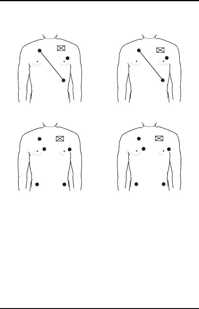
Preparation for Monitoring ECG Monitoring ECG
7 - 8 TMS60 Operator’s Manual
7.3.4.3 Lead Placement: Pacemaker Patients
The recommended lead placement for monitoring a pacemaker patient is as follows.
A pacemaker patient usually requires a different electrode patch placement configura-
tion than a non-pacemaker patient.
Do not place an ECG electrode directly over the pacemaker generator. Place the elec-
trode patches 3 to 5 inches away from the pacemaker generator area. For example, if the
pacemaker generator is located in the right subclavian area, relocate the Right Arm elec-
trode closer in towards the center of the chest.
3-wire lead placement for a pacemaker patient
(AHA)
3-wire Lead Placement for a Pacemaker Patient
(IEC)
5-wire Lead Placement for a Pacemaker Patient
(AHA)
5-wire Lead Placement for a Pacemaker Patient
(IEC)
RA
LA
LL
Pacer
R
L
F
Pacer
Pacer
RA
VLA
LL
RL
Pacer
R
L
C
NF
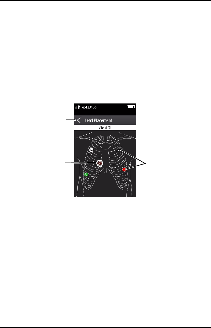
Monitoring ECG Preparation for Monitoring ECG
TMS60 Operator’s Manual 7 - 9
7.3.5 Checking the Lead Placement
With the Lead Placement function, you can check the lead status, information, and lead
off messages.
7.3.5.1 Entering the Lead Placement Menu
Enter the [Lead Placement] menu in either of the following ways:
■Tap the lead fault message in the message area of the main screen.
■In the main menu, tap [Lead Placement].
7.3.5.2 Understanding the Lead Placement Instructions
The [Lead Placement] window indicates the lead status.
When any of the leads are off, the indications are as follows:
■The lead off message displays on the information bar.
The background color of the information bar corresponds to the alarm level.
■A flashing circle indicates the disconnected lead.
The color of the flashing circle is based on the alarm level.
Example lead placement window
Information bar
Lead off indicator Lead on indicator
Preparation for Monitoring ECG Monitoring ECG
7 - 10 TMS60 Operator’s Manual
7.3.6 Checking the Paced Status
It is important to correctly set the patient’s paced status before you start monitoring
ECG.
To check the paced status:
■On the main screen, tap the HR digital area or ECG waveform area to enter the
[ECG] menu.
OR
1. In the main menu, tap [Patient Info].
2. In the [Pacer] field, check the setting of the paced status.
The current paced status setting displays to the right of [Paced].
3. If the paced status setting is not correct, tap [Paced] and select the correct paced
status.
■When [Paced] is set to [Yes ] at the TD60, and the pacer pulse is detected, the
symbol displays in the waveform area of the CS screen, and the pace pulse marks
will display on the ECG waveform both at the TD60 and CS.
■When [Paced] is set to [No] at the TD60, and the pacer pulse is detected, the
symbol displays in the waveform area of the CS screen.
WARNING
•For paced patients, you must set [Paced] to [Yes]. If it is incorrectly set to
[No], the CS could mistake a pace pulse for a QRS and fail to alarm when
the ECG signal is too weak. Do not rely entirely on rate meter alarms
when monitoring patients with pacemakers. Always keep these patients
under close surveillance.
•The pacer pulses may be counted as QRS complexes, hence leading to
wrong HR readings or failure to diagnose certain arrhythmia symptoms.
Be sure to keep a close eye on patient’s with pacemaker devices.
•For non-paced patients, you must set [Paced] to [No].
•False low heart rate indicators or false asystole calls may result with cer-
tain pacemakers because of pacemaker artifact such as electrical over-
shoot of the pacemaker overlapping the true QRS complexes.
•In order to minimize the possibility of interference, place electrodes,
leadwires and TD60s as far away from the pacemaker as possible.

Monitoring ECG Changing the ECG Settings
TMS60 Operator’s Manual 7 - 11
7.4 Changing the ECG Settings
You can change the ECG settings from the ECG menu.
7.4.1 Configuring the ECG Setup
Enter the ECG menu in either of the following ways:
■On the main screen, tap the HR digital area or ECG waveform area to enter the
[ECG] menu.
■In the main menu, tap [Parameter Setup] → [ECG] to enter the [ECG] menu.
1. In the [Setup] section of the [ECG] menu, select the options described in the fol-
lowing table.
NOTE
•When [Paced] is set to [Yes], the system does not detect PVC-related
arrhythmia (including PVCs) resulting from pacemaker but still analyzes
the normal QRS complex.
Options Description Settings*
Lead Placement Enters the [Lead Placement] window. Refer to "Checking the Lead
Placement" on page 7 - 9 for
details.
Cable Type Selects the current ECG leadwire type. Auto, 3 Lead, 5 Lead
Refer to "ECG Leadwire Types" on
page 7 - 12 for details.
Smart Lead (Monitored
Lead)
When [Cable Type] is set to [Auto], the option displays [Smart Lead].
Drag the swtich to right or left to enable or disable the Smart Lead function.
When [Cable Type] is set to [3 Lead], the option displays [Monitored Lead].
Refer to "ECG Leadwire Types" on page 7 - 12 for details.
* The factory default settings are in bold.

Changing the ECG Settings Monitoring ECG
7 - 12 TMS60 Operator’s Manual
2. Tap to exit the [ECG] menu.
7.4.2 ECG Leadwire Types
ECG leadwire type has three options as follows:
■[Auto]: the device automatically sets the leadwire type according to the leadset
connected.
■[3 Lead]: the leadwire type is set to 3-lead.
If the leadwire type is set to 3-lead, the [Smart Lead] option becomes [Monitored
Lead]. You can select the desired lead from the [Monitored Lead] option to set
the first ECG waveform displayed on the main screen.
■[5 Lead]: the leadwire types is set to 5-lead.
All waveform leads display on the main screen.
7.4.3 Configuring the ECG Waveforms
1. In the [Waveform] section of the [ECG] menu, select the options described in the
following table.
Filter Selects the ECG filter.
Monitor
Use under normal measurement
conditions.
ST
Use when ST monitoring is applied.
Monitor, ST
Color Selects the ECG waveform color. 16 colors
The default color is green.
Options Description Settings*
* The factory default settings are in bold.
Options Description Settings*
All Lead Size Selects the waveform size for all the leads.
To set the waveform size for a specific
lead, select that lead from the [Waveform
Size] section.
1.25 mm/mV, 2.5 mm/mV, 5 mm/
mV, 10 mm/mV, 20 mm/mV, 40
mm/mV, Auto
This configuration will be applied for all ECG waveform size.
* The factory default settings are in bold.

Monitoring ECG Changing the ECG Settings
TMS60 Operator’s Manual 7 - 13
2. Tap to exit the [ECG] menu.
7.4.4 Configuring the Pacer
1. In the [Pacer] section of the [ECG] menu, tap the options described in the follow-
ing table.
2. Tap to exit the [ECG] menu.
Speed Selects the waveform sweep speed. 6.25 mm/s, 12.5 mm/s, 25 mm/s
Options Description Settings*
* The factory default settings are in bold.
Options Description Settings*
Paced Selects the paced status. Unspecified, No, Yes
[Unspecified] is only available for
the first time you set the paced sta-
tus.
Refer to "Checking the Paced Sta-
tus" on page 7 - 10 for details.
Markers Selects the pacer indicator.
Line
A 1 cm line shows above each ECG wave-
form each time the pace pulse is detected.
Dot
A 2 mm dot shows above each ECG wave-
form each time the pace pulse is detected.
Line, Dot, Off
Pacer Reject Selects whether or not to reject the pace
pulses.
On, Off
* The factory default settings are in bold.
NOTE
•When [Paced] is set to [Yes], the [Markers] and [Pacer Rejection] options
can be available.
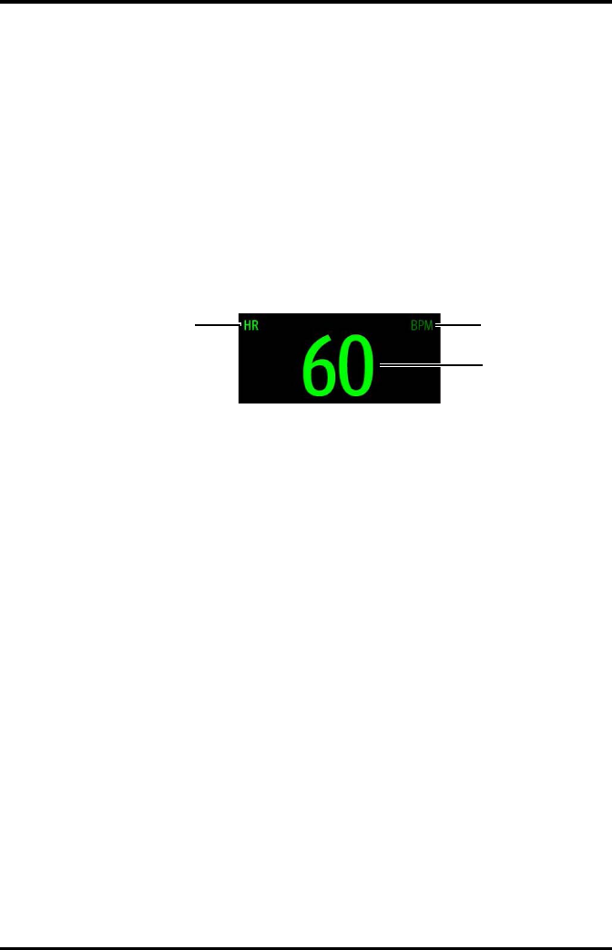
Understanding the ECG Display Monitoring ECG
7 - 14 TMS60 Operator’s Manual
7.4.5 Configuring the ECG Waveform Size
The [Waveform Size] section of the [ECG] menu lists all available leads. You can select
the desired ECG lead to set the waveform size.
7.5 Understanding the ECG Display
7.5.1 HR Digital Area
The HR digital area displays:
1. Parameter name
2. Measurement unit
3. Heart rate value
7.5.2 About the HR Digital Area
■The HR area displays heart rate in the unit of bpm with a resolution of 1 bpm.
■If the HR measurement is invalid, “- - -” displays in place of the HR value.
■The HR value displays “0”, when the HR value is less than 15 bpm.
12
3

Monitoring ECG Understanding the ECG Display
TMS60 Operator’s Manual 7 - 15
7.5.3 ECG Waveform Area
The ECG waveform area displays:
1. ECG Lead
2. ECG scale bar
3. ECG waveform
4. ECG filter setting
5. ECG scale
7.5.4 About the ECG Waveform Area
■The ECG waveform, scale indicator, lead, and filter settings display in the
configured ECG color.
■The ECG waveform area provides scrolling, real-time waveform data and an erase
bar to provide a time indicator of oldest and new data.
■The ECG waveform area scrolls the waveform in the configured sweep speed.
■The ECG waveform area rails the top most value when the waveform exceeds the
upper scale limit for real-time waveforms.
■The ECG waveform area rails the bottom most value when the waveform exceeds
the lower scale limit for real-time waveforms.
■The ECG waveform area indicates a Pacer indicator when a pace pulse is detected
and Paced is enabled.
13
4
5
2

Understanding the ECG Display Monitoring ECG
7 - 16 TMS60 Operator’s Manual
This page intentionally left blank.

TMS60 Operator’s Manual 8 - 1
8Monitoring SpO2 (Optional)
Introduction...............................................................................................................8-2
Measurement Limitations.....................................................................................8-2
Safety............................................................................................................................8-3
Connecting the SpO2 Module ............................................................................8-4
Changing the SpO2 Settings ...............................................................................8-5
SpO2 Measurement................................................................................................8-8
Understanding the SpO2 Display ......................................................................8-10

Introduction Monitoring SpO2 (Optional)
8 - 2 TMS60 Operator’s Manual
8.1 Introduction
The chapter describes the SpO2 monitoring function at the TD60 in detail, including
connecting the SpO2 module, configuring the SpO2, and monitoring the SpO2. For
details about the SpO2 parameter setup at the central station (CS), refer to Chapter 9
Monitoring with the TD60 at the CS.
SpO2 monitoring is a non-invasive technique used to measure the amount of
oxygenated hemoglobin and pulse rate by measuring the absorption of selected
wavelengths of light. The light generated in the probe passes through the tissue and is
converted into electrical signals by the photo detector in the probe. The SpO2 module
processes the electrical signal and displays a waveform and digital values for SpO2 and
pulse rate.
The TD60 can be configured with Masimo SpO2 or Nonin SpO2.
8.2 Measurement Limitations
If the SpO2 measurement seems out of range or inaccurate, check the patient’s vital
signs. Then check the equipment and SpO2 sensor. The following factors may influence
the accuracy of measurement:
■Ambient light
■Physical movement
■Low perfusion
■Electromagnetic interference
NOTE
•A functional tester or SpO2 simulator cannot be used to assess the
accuracy of a SpO2 module or a SpO2 sensor.
•This device is calibrated to display functional oxygen saturation.
•A pulse oximeter should not be used as an apnea monitor.
•Pulse rate measurement is based on the optical detection of a
peripheral flow pulse and therefore may not detect certain arrhythmias.
The pulse oximeter should not be used as a replacement or substitute
for ECG based arrhythmia analysis.
•The MS board pulse oximeter can be used during defibrillation, but the
readings may be inaccurate for a short time.

Monitoring SpO2 (Optional) Safety
TMS60 Operator’s Manual 8 - 3
■Dysfunctional hemoglobin, such as carboxyhemoglobin (COHb) and
methemoglobin (MetHb)
■Presence of certain dyes, such as methylene and indigo carmine
■Inappropriate positioning of the SpO2 sensor, or use of incorrect SpO2 sensor
■Drop of arterial blood flow to immeaurable level caused by shock, anemia, low
temperature or vasoconstrictor.
■Inaccurate measurements may be caused by venous pulsations.
■Placement of a sensor on an extremity that has a blood pressure cuff, arterial
catheter, or intra-vascular line.
■Loss of pulse signal can occur when the sensor is too tight.
■Loss of pulse signal can occur when there is arterial occlusion proximal to the
sensor.
8.3 Safety
WARNING
•Only use SpO2 sensors specified in this manual. Follow the SpO2 sensor’s
instructions for use and adhere to all warnings and cautions.
•The operator is responsible for checking the compatibility of the pulse
oximetry monitor, sensor, and patient cable prior to use. Incompatible
components can result in degraded performance and/or device
malfunction.
•When a trend toward patient deoxygenation is indicated, blood samples
should be analyzed by a laboratory co-oximeter to completely
understand the patient’s condition.
•Do not use SpO2 sensors during magnetic resonance imaging (MRI).
Induced current could potentially cause burns. The sensor may affect
the MRI image, and the MRI unit may affect the accuracy of the oximetry
measurements.
•Prolonged and continuous monitoring may increase the temperature of
the sensor and cause the patient discomfort. It is especially important to
check the sensor placement, and ensure proper attachment on patients
suffering from poor perfusion or skin sensitivity. Check the sensor
location every two to three hours and move to another location if the
skin deteriorates. More frequent examinations may be required for
different patients.
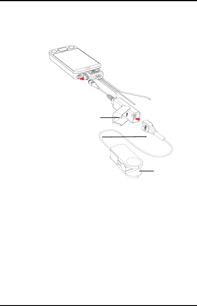
Connecting the SpO2 Module Monitoring SpO2 (Optional)
8 - 4 TMS60 Operator’s Manual
8.4 Connecting the SpO2 Module
Connect the SpO2 module to the TD60. The TD60 can auto detect the SpO2 module type
when the SpO2 module is connected.
Connecting the Masimo SpO2 module
SpO2 module
SpO2 sensor
SpO2 sensor con-
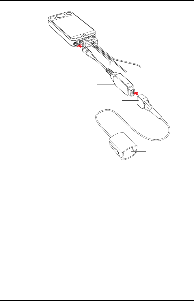
Monitoring SpO2 (Optional) Changing the SpO2 Settings
TMS60 Operator’s Manual 8 - 5
Connecting the Nonin SpO2 module
8.5 Changing the SpO2 Settings
You can change the SpO2 settings from the SpO2 menu.
8.5.1 Configuring the SpO2 Setup
Enter the SPO2 menu in either of the following ways:
■On the main screen, tap the SpO2 digital area or SpO2 waveform area to enter the
[SpO2] menu.
■In the main menu, tap [Parameter Setup] → [SpO2] to enter the [SpO2] menu.
1. In the [Setup] section of the [SpO2] menu, select the options described in the fol-
lowing table.
SpO2 module
SpO2 sensor
SpO2 sensor connector

Changing the SpO2 Settings Monitoring SpO2 (Optional)
8 - 6 TMS60 Operator’s Manual
Options Description Settings*
Display PI
(Masimo only)
Configures whether or not to show the
perfusion index (PI) value in the digital area.
The perfusion index allows clinicians to assess
the pulse strength at the monitoring site for
optimal sensor placement.
PI gives the numerical value for the
pulsatile to non-pulsatile portion of the
measured signal caused by arterial pulsation. PI
is an indicator of the pulsatile strength.
On, Off
Sensitivity
(Masimo only)
Selects the sensitivity mode depending upon
signal quality and patient motion.
High:
This mode should be used for the sickest
patients, where obtaining a reading is most
difficult. High Sensitivity is designed to interpret
and display data for even the weakest of signals.
This mode is recommended during procedures
and when clinician and patient contact is
continuous.
Normal:
This mode provides the best combination of
sensitivity and probe off detection performance.
This mode is recommended for the majority of
patients.
APOD (Adaptive Probe Off Detection):
This mode is the least sensitive in picking up a
reading on patients with low perfusion but has
the best detection for probe-off conditions. This
mode is useful for patients that are at particular
risk of the sensor becoming detached (pediatric,
combative, etc.)
High, Normal, and APOD
* The factory default settings are in bold.

Monitoring SpO2 (Optional) Changing the SpO2 Settings
TMS60 Operator’s Manual 8 - 7
2. Tap to exit the [SpO2] menu.
Averaging
(Masimo only)
The user-selectable averaging feature allows the
clinician to select the desired level of visibility to
subtle variations in the measured value.
Depending on the patient acuity and area of
care, shorter averaging times are sometimes
preferred (sleep testing) over longer averaging
times (telemetry) and vice-versa.
8-second averaging is generally considered the
most common averaging interval and
recommended for most patients since it is short
enough to provide visibility to subtle
desaturations while also being long enough to
minimize major changes in SpO2 due to quick,
transitory desaturations. Although averaging
times greater than 10 seconds are more likely to
reduce visibility to rapid, brief desaturations, this
may be desirable in care areas where brief
desaturations that do not require clinician
intervention occur more often (such as NICU). It
is also recommended that this be enabled as a
“sticky” configuration so as to hold the setting
after power cycles.
2-4 sec, 4-6 sec, 8 sec, 10
sec, 12 sec, 14 sec, 16 sec
Fast SAT
(Masimo only)
Selects whether or not to enable FastSat. FastSat
enables rapid tracking of arterial oxygen
saturation changes as may be required in urgent
situations.
On, Off
Color Selects the SpO2 waveform color. 16 colors
The default color is cyan.
Options Description Settings*
* The factory default settings are in bold.

SpO2 Measurement Monitoring SpO2 (Optional)
8 - 8 TMS60 Operator’s Manual
8.5.2 Configuring the SpO2 Waveform
1. In the [Waveform] field of the [SpO2] menu, select the options described in the
following table.
2. Tap to exit the [SpO2] menu.
8.6 SpO2 Measurement
8.6.1 Identifying SpO2 Modules
To identify which SpO2 module you are using, see the company logo on the SpO2
module.
■Masimo SpO2 module: white, with a logo of Masimo SET.
■Nonin SpO2 module: blue, with a logo of Nonin.
8.6.2 Applying the Sensor
1. Select an appropriate sensor according to the module type, patient size, and
weight.
2. Remove colored nail polish from the application site.
3. Apply the sensor to the patient.
4. Connect the sensor to the SpO2 module and the SpO2 module to the TD60.
The SpO2 measurement displays when the TD60 detects that a sensor is con-
nected to the patient.
Options Description Settings*
Speed Selects the SpO2 pleth waveform speed. 6.25 mm/s, 12.5 mm/s, 25
mm/s
Display SIQ
(Masimo only)
Selects whether or nor to show the Signal
Indicator Quality (SIQ) in the SpO2 waveform
area. The SIQ wave indicates the confidence
associated with the saturation measurement
and timing of the pulse. Higher pulse indicates a
better signal.
On, Off
* The factory default settings are in bold.

Monitoring SpO2 (Optional) SpO2 Measurement
TMS60 Operator’s Manual 8 - 9
WARNING
•When equipped with Masimo SpO2 module, use only Masimo SpO2
sensors specified in this manual. Use of other SpO2 sensors may cause
improper oximeter performance.
•When equipped with Nonin SpO2 module, use only Nonin SpO2 sensors
specified in this manual. Use of other SpO2 sensors may cause improper
oximeter performance.
•Do not disconnect the Nonin Spo2 sensor connector from the Nonin
SpO2 module during defibrillation.
•If the sensor is too tight because the application site is too large or
becomes too large due to edema, excessive pressure for prolonged
periods may result in venous congestion distal from the application site,
leading to interstitial edema and tissue ischemia.
CAUTION
•Many patients suffer from poor peripheral perfusion due to
hypothermia, hypovolemia, severe vasoconstriction, reduced cardiac
output, etc. These symptoms may cause a loss in vital sign readings.
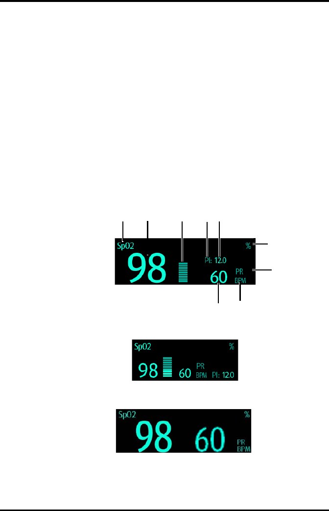
Understanding the SpO2 Display Monitoring SpO2 (Optional)
8 - 10 TMS60 Operator’s Manual
8.7 Understanding the SpO2 Display
8.7.1 SpO2 Digital Area
The SpO2 digital area displays:
1. Parameter name
2. SpO2 value
3. Perfusion indicator
4. Perfusion index (PI) label
5. Perfusion index value
6. SpO2 unit of measure
7. Pulse rate (PR) label
8. PR measurement unit
9. PR value
Masimo SpO2 digital area (for portrait display)
Masimo SpO2 digital area (for landscape display)
Nonin SpO2 digital area
123
6
7
8
9
5
4
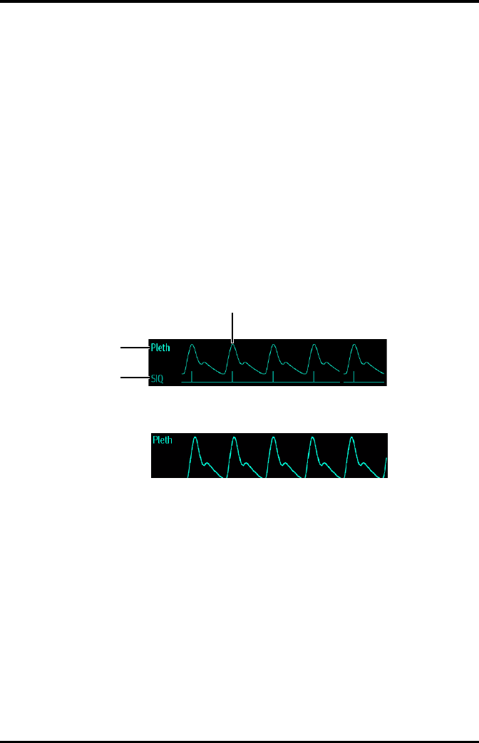
Monitoring SpO2 (Optional) Understanding the SpO2 Display
TMS60 Operator’s Manual 8 - 11
8.7.2 About the SpO2 Digital Area
■The SpO2 digital area displays in units of % with a resolution of 1%.
■The SpO2 PR value displays in units of bpm with a resolution of 1 bpm.
■Displays Masimo PI resolution as 0.01 when the PI value is smaller than 10%.
■Displays Masimo PI resolution as 0.1 when the PI value is greater than or equal to
10%.
■If the SpO2 measurement or PR is invalid, “- - -” displays in place of digits.
8.7.3 SpO2 Waveform Area
The SpO2 waveform area displays:
1. Signal Indicator Quality (SIQ)
2. Area name
3. Pleth waveform
Masimo SpO2 waveform area (SIQ enabled)
Nonin SpO2 waveform area
8.7.4 About the SpO2 Waveform Area
■Displays in the configured SpO2 color.
■Provides scrolling, real-time waveform data.
■Scrolls the waveform in the configured sweep speed.
■Automatically scales the SpO2 waveform data area to maximize the vertical height
of the Pleth waveform for the data range.
■If using Masimo SpO2, the Signal Quality Index (SIQ) will display below the
waveform if enabled.
3
2
1

Masimo Information Monitoring SpO2 (Optional)
8 - 12 TMS60 Operator’s Manual
8.8 Masimo Information
■Masimo Patents
This device is covered under one or more the following U.S.A. patents: 5,758,644;
5,823,950; 6,011,986; 6157,850; 6,263,222; 6,501,975; 7,469,157 and other applica-
ble patents listed at: www.masimo.com/patents.htm.
■No Implied License
Possession or purchase of this device does not convey any express or implied
license to use the device with unauthorized sensors or cables which would, alone,
or in combination with this device, fall within the scope of one or more of the pat-
ents relating to this device.

TMS60 Operator’s Manual 9 - 1
9Monitoring with the TD60 at the CS
Introduction...............................................................................................................9-2
Physiological Alarms...............................................................................................9-2
ECG Monitoring ........................................................................................................9-12
QT Monitoring...........................................................................................................9-18
ST Monitoring............................................................................................................9-22
Arrhythmia Monitoring..........................................................................................9-27
SpO2 Monitoring .....................................................................................................9-33

Introduction Monitoring with the TD60 at the CS
9 - 2 TMS60 Operator’s Manual
9.1 Introduction
The chapter describes the configurations and displays at the central station (CS) once
the TD60 is connected to the CS.
At the CS, Mindray ECG algorithm and Mortara ECG algorithm are available. You can
select either algorithm as required.
9.2 Physiological Alarms
At the CS, you can view and change the physiological alarm limits and alarm levels in the
[Alarm Setup] menu. The [Alarm Setup] menu has three tabs:
■[Parameter Alarm Settings]: view and change the parameter alarm limits, alarm
levels and alarm responses.
■[Arrhythmia Alarms]: view and change the arrhythmia alarms levels, and alarm
responses.
■[Arrh. Threshold Setup]: view and change the arrhythmia threshold settings for
some arrhythmia alarms.
For details about the [Alarm Setup] menu, refer to the BeneVision Central Station
Operator’s Manual (P/N 046-005011-00).
WARNING
•Be aware that the devices in your care area may each have different
alarm settings to suit different patients. Always check that the alarm set-
tings are appropriate for your patient before you start monitoring.
•A potential hazard can exist if different alarm presets are used for the
same or similar equipment in any single area, such as an intensive care
unit or cardiac operating room.
•Make sure that the alarm limits settings are appropriate for your patient
before monitoring.
•When monitoring patients that are not continuously attended by a clini-
cal operator, properly configure the alarm system and adjust alarm set-
tings as per the patient's condition.
•Setting alarm limits to extreme values may cause the alarm system to
become ineffective. For example, high oxygen levels may predispose a
premature infant to retrolental fibroplasia. If this is a consideration do
NOT set the high alarm limit to 100%, which is equivalent to switching
the alarm off.

Monitoring with the TD60 at the CS Physiological Alarms
TMS60 Operator’s Manual 9 - 3
9.2.1 Factory Default Parameter Alarm Limits
The following table lists the factory default alarm limits for all parameters.
WARNING
•If you switch off all arrhythmia alarms, the CS cannot give any arrhyth-
mia alarms. Always keep the patient under close surveillance.
Parameters Alarm limit Adult Pediatric
HR
Unit of measure: bpm
Invalid data: “--”
High limit (Low limit + 2) to 300
Default: 120
(Low limit + 2) to 350
Default: 160
Low limit 15 to (high limit - 2)
Default: 50
15 to (high limit - 2)
Default: 75
ST Single
Unit of measure: mV
Invalid data: “--”
High limit (Low limit + 0.2) to 2.00
Default: 0.2
(Low limit + 0.2) to 2.00
Default: 0.2
Low limit -2.00 to (high limit – 0.2)
Default: -0.2
-2.00 to (high limit – 0.2)
Default: -0.2
ST Dual
Unit of measure: mV
Invalid data: “--”
High limit (Low limit + 0.2) to 2.00
Default: 0.2
(Low limit + 0.2) to 2.00
Default: 0.2
Low limit -2.00 to (high limit – 0.2)
Default: -0.2
-2.00 to (high limit – 0.2)
Default: -0.2
QTc
Unit of measure: ms
Invalid data: “--”
High limit 200 to 800
Default: 500
200 to 800
Default: 480
Low limit N/A N/A
∆QTc*
Unit of measure: ms
Invalid data: “--”
High limit 30 to 200
Default: 60
30 to 200
Default: 60
Low limit N/A N/A
SpO2
Unit of measure: %
Invalid data: “--”
High limit (Low limit + 1) to 100
Default: 100
(Low limit + 1) to 100
Default: 100
Low limit 0 to (high limit - 1)
Default: 90
0 to (high limit - 1)
Default: 90
* ΔQTc is only available for Mindray ECG algorithm.

Physiological Alarms Monitoring with the TD60 at the CS
9 - 4 TMS60 Operator’s Manual
9.2.2 Parameter Alarm Responses
At the CS, the following parameter alarm responses may occur when a parameter alarm
occurs.
■Record on Alarm: directs the CS to send the alarm data to the configured recorder.
■Print on Alarm: directs the CS to send the alarm data to the configured printer.
■Paging Switch: directs the CS to send an alarm to the beeper to notify the clinician.
SpO2 Desat
Unit of measure: %
Invalid data: “--”
High limit N/A N/A
Low limit 0 to 100
Default: 80
0 to 100
Default: 80
PR
Unit of measure: bpm
Invalid data: “--”
High limit (Low limit + 2) to 300
Default: 120
(Low limit + 2) to 300
Default: 160
Low limit 18 to (high limit - 2)
Default: 50
18 to (high limit - 2)
Default: 75
Parameters Alarm limit Adult Pediatric
* ΔQTc is only available for Mindray ECG algorithm.
NOTE
•The SpO2 Desat alarm limit is restricted such that the alarm limit can not
be higher than the SpO2 low limit.

Monitoring with the TD60 at the CS Physiological Alarms
TMS60 Operator’s Manual 9 - 5
9.2.3 Factory Default Parameter Alarm Settings
The following table lists the factory default alarm levels and responses for all parameters.
Parameters
Alarm levels*
Activation
State
Factory default alarm responses
High Medium Low Record on
Alarm
Print on
Alarm
Paging
Switch
HR X X** — On Off Off Off
ST Single X XX Off Off Off Off
ST Dual X XX Off Off Off Off
QTc X XX Off Off Off Off
∆QTc*** X XX Off Off Off Off
SpO2XX— On Off Off Off
SpO2
Desat****
X——On Off Off Off
PR X X— On Off Off Off
* X indicates available alarm level, — indicates alarm level not available
** The factory default settings are in bold.
*** ΔQTc is only available for Mindray ECG algorithm.
**** The alarm level option for SpO2 Desat is not configurable. [High] is the only alarm level and cannot be
changed.

Physiological Alarms Monitoring with the TD60 at the CS
9 - 6 TMS60 Operator’s Manual
9.2.4 Factory Default Arrhythmia Alarm Settings
9.2.4.1 Mindray Algorithm
Parameters
Alarm levels*
Activation
State
Factory default alarm
responses
High Medium Low Message
Record
on
Alarm
Print
on
Alarm
Paging
Switch
Asystole X** — — — On Off Off Off
VFib/VTac X— — — On Off Off Off
VTac X— — — On Off Off Off
Vent. Brady X— — — On Off Off Off
Extreme
Tachy X— — — On Off Off Off
Extreme
Brady X— — — On Off Off Off
PVCs/min X XX X On Off Off Off
R on T X XX X On Off Off Off
Run PVCs X X XX Off Off Off Off
Couplet X X X XOff Off Off Off
PVC X X X XOff Off Off Off
Vent.
Rhythm
XXX X On Off Off Off
Bigeminy X XX X On Off Off Off
Trigeminy X XX X On Off Off Off
Tachy X XX X Off Off Off Off
Brady X XX X Off Off Off Off
Pacer Not
Pacing
XX XXOff Off Off Off
* X indicates available alarm level, — indicates alarm level not available
** The factory default settings are in bold.

Monitoring with the TD60 at the CS Physiological Alarms
TMS60 Operator’s Manual 9 - 7
Pacer Not
Capture
XX XXOff Off Off Off
Missed Beat X X X XOff Off Off Off
Multif. PVC X XX X Off Off Off Off
Nonsus.
Vtac
XXX X On Off Off Off
Pause X X XX Off Off Off Off
AFib X X X XOff Off Off Off
Irr.Rhythm — — X XOff Off Off Off
Pauses/min X XX X On Off Off Off
Parameters
Alarm levels*
Activation
State
Factory default alarm
responses
High Medium Low Message
Record
on
Alarm
Print
on
Alarm
Paging
Switch
* X indicates available alarm level, — indicates alarm level not available
** The factory default settings are in bold.
NOTE
•When [Paced] is set to [Yes], the Missed Beat (MIS) alarm is reported as
the pacer not captured (PNC) or pacer not paced (PNP) alarm.

Physiological Alarms Monitoring with the TD60 at the CS
9 - 8 TMS60 Operator’s Manual
9.2.4.2 For Mortara Algorithm
Parameters
Alarm levels*
Activation
State
Factory default alarm
responses
High Medium Low Message
Record
on
Alarm
Print
on
Alarm
Paging
Switch
Asystole X** — — — On Off Off Off
VFib X— — — On Off Off Off
VTac X— — — On Off Off Off
Extreme
Tachy X— — — On Off Off Off
Extreme
Brady X— — — On Off Off Off
PVCs/min X XX X On Off Off Off
R on T X XX X On Off Off Off
Run PVCs X X XX Off Off Off Off
Couplet X X X XOff Off Off Off
Vent.
Rhythm
XXX X On Off Off Off
Bigeminy X XX X On Off Off Off
Trigeminy X XX X On Off Off Off
Tachy X XX X Off Off Off Off
Brady X XX X Off Off Off Off
Pacer Not
Pacing
XX XXOff Off Off Off
Pacer Not
Capture
XX XXOff Off Off Off
Multif. PVC X XX X Off Off Off Off
Pause X X XX Off Off Off Off
* X indicates available alarm level, — indicates alarm level not available
** The factory default settings are in bold.

Monitoring with the TD60 at the CS Physiological Alarms
TMS60 Operator’s Manual 9 - 9
In addition, the activation state of some arrhythmias can be set as a whole with the fol-
lowing buttons that are at the bottom of the [Arrhythmia Alarms] tab.
Irr.Rhythm — — X XOff Off Off Off
Pauses/min X XX X On Off Off Off
Parameters
Alarm levels*
Activation
State
Factory default alarm
responses
High Medium Low Message
Record
on
Alarm
Print
on
Alarm
Paging
Switch
* X indicates available alarm level, — indicates alarm level not available
** The factory default settings are in bold.
NOTE
•The priority of lethal arrhythmia alarms is always high. It is unchange-
able.
Button Description
Lethals Only Sets the lethal arrhythmia alarms to on and all non-lethal arrhythmia alarms to off.
All Alarm On Sets all arrhythmia alarms to on.
All Alarm Off Sets all arrhythmia alarms to off.
This button is enabled when the [Lethal Arrh. OFF] option in the [Telemetr y] tab
from the [Admin Setup] menu is set to [Enable].

Physiological Alarms Monitoring with the TD60 at the CS
9 - 10 TMS60 Operator’s Manual
9.2.5 Arrhythmia Threshold Settings
When an arrhythmia violates its threshold, an alarm is triggered. For the Mortara algo-
rithm, the setting of asystole delay is related to arrhythmia relearn. When HR is less than
30 bpm, it is recommended to set asystole delay to 10 s.
9.2.5.1 Mindray ECG algorithm
Arrh. event Range or Option Default Step Unit of
measure
PVCs High 1 to 100 10 1 minute
Pauses/min 1 to 15 8 1 N/A
Asys. Delay 3 to 10 4 1 second
Tachy High 60 to 300 Adult: 120
Pediatric: 160
5bpm
Brady Low 15 to 120 Adult: 50
Pediatric: 75
5bpm
Extreme Tachy 60 to 300 Adult: 160
Pediatric: 180
5bpm
Extreme Brady 15 to 120 Adult: 35
Pediatric: 50
5bpm
Multif. PVC’s Window 3 to 31 15 1 /min
Vtac Rate 100 to 200 130 5 bpm
Vtac PVC 3 to 99 6 1 beat
Pause Time 1.5, 2.0, and 2.5 2.0 N/A second
Vbrd Rate 15 to 60 40 5 bpm
Vbrd PVCs 3 to 99 5 1 beat

Monitoring with the TD60 at the CS Physiological Alarms
TMS60 Operator’s Manual 9 - 11
9.2.5.2 Mortara ECG algorithm
Arrh. event Range or Option Default Step Unit
PVCs High 1 to 100 10 1 minute
Pauses/min 1 to 15 8 1 N/A
Asys. Delay 2 to 10 4 1 seconds
Vtac Rate 100 to 200 130 5 bpm
Vtac PVC 3 to 12 6 1 beat
Extreme Tachy Adult: 100 to 300
Pediatric: 160 to 300
Adult: 160
Pediatric: 180
5bpm
Extreme Brady Adult: 15 to 60
Pediatric: 15 to 80
Adult: 35
Pediatric: 50
5bpm
Multif. PVC’s Window 3 to 31 15 1 /min
Tachy High Adult: 100 to 300
Pediatric: 160 to 300
Adult: 120
Pediatric: 160
5bpm
Brady Low Adult: 15 to 60
Pediatric: 15 to 80
Adult: 50
Pediatric: 75
5bpm
Pause Threshold RR 1.2, 1.3, 1.4, 1.5, 1.6,
1.7, 1.8, 1.9, and 2.0
2.0 N/A s

ECG Monitoring Monitoring with the TD60 at the CS
9 - 12 TMS60 Operator’s Manual
9.3 ECG Monitoring
At the CS, you can view and change the heart rate (HR), QT, ST, and arrhythmia settings in
the [ECG] tab of the [Parameter Setup] menu.
For details about the [Parameter Setup] menu, refer to the BeneVision Central Station
Operator’s Manual (P/N 046-005011-00).
9.3.1 HR Settings
The following table lists the HR settings in the [HR] section of the [ECG] tab.
Options or Buttons Description Settings*
HR Activation State Configures whether or not to enable the
HR alarm.
On, Off
HR Alarm Priority Configures the HR alarm levels. High, Med
HR High Limit (bpm) Configures the HR high alarm limit. Adult:
(Low limit + 2) to 300
The default is 120.
Pediatric:
(Low limit + 2) to 350
The default is 160.
HR Low Limit (bpm) Configures the HR low alarm limit. Adult:
15 to (high limit - 2)
The default is 50.
Pediatric:
15 to (high limit - 2)
The default is 75.
Pacer Rate (bpm) (only
Mortara ECG algorithm)
When some pacemaker pulses are difficult
to reject, the pulses are counted as a QRS
complex and could result in an incorrect
HR and failure to detect some arrhythmias.
Configures the pacemaker rate, the sys-
tem can calculate HR and detect arrhyth-
mias more accurately.
40 to 100
The default is 60.
The option is unavailable when [Paced] is set to [No] at the TD60. For details
about the paced status, refer to "Checking the Paced Status" on page 7 - 10.
Sweep Speed Configures the ECG wave speed. 6.25 mm/s, 12.5 mm/s, 25 mm/s,
50 mm/s
HR Source Configures the HR source. ECG, SpO2, Auto, Both
* The factory default settings are in bold.

Monitoring with the TD60 at the CS ECG Monitoring
TMS60 Operator’s Manual 9 - 13
9.3.2 Waveform Setup
The ECG leads waveforms displayed in the waveform area are defined as the displaying
lead.
The CS uses information from two leads to detect beats and to compute HR. These two
leads are referred to as the primary and secondary leads. In addition, for Mortara ECG
algorithm, information from an additional lead (analysis lead) is made use of to classify
the beats (normal, abnormal etc). The user can select any of the available leads (depend-
ing on whether a 3 or 5 lead cable is used) as primary, secondary or other analysis leads.
For best results, the following guidelines should be used:
■The QRS complex should be tall, narrow and preferably either completely above or
below the baseline. If at all possible, avoid selecting a lead where the QRS complex
is biphasic.
■The P-waves and T-waves should be small compared to the QRS. They should be
less than about 0.2 mV.
9.3.2.1 Changing the Setting for Analysis Leads and Displaying Leads
The default system setting for the analysis leads and displaying leads is [On], which
means that the analysis leads are consistent with the displaying leads. You can change
the default setting as following steps, if necessary.
1. At the CS, click [Admin Setup] → input the password → [OK].
2. In the [Admin Setup] menu, click the [Telemetr y] tab.
3. On the left side of the [Telemetry] tab, click [Analysis Lead Setting].
The corresponding setting displays to the right of [Telemetr y].
4. Set [Consistent with Displayed Lead] to [On] or [Off].
◆[On]: the analysis lead is the same as the displaying lead.
◆[Off]: the analysis lead is different from the displaying lead.
HR Record on Alarm Select whether or not to activate the
option to direct the CS to send the HR
alarm data to the configured recorder.
On, Off
Waveform Setup Select to display the [Waveform Setup]
menu.
Refer to "Waveform Setup" on
page 9 - 13 for details.
Other Settings Select to display the [Other Settings]
menu.
Refer to "Other Settings" on page
9 - 15 for details.
Options or Buttons Description Settings*
* The factory default settings are in bold.

ECG Monitoring Monitoring with the TD60 at the CS
9 - 14 TMS60 Operator’s Manual
9.3.2.2 Changing ECG Wave Settings
In the [Waveform Setup] menu, you can configure the displaying leads and analysis
leads as desired. The lead settings are dependent on the setting of [Analysis Lead Set-
ting].
■When [Analysis Lead Setting] is set to [On], the ECG waveform configurations are
applied for the displaying leads and analysis leads. Follow the steps below to con-
figure the ECG waveform setting:
1. In the [HR] section of the [ECG] tab, click [Waveform Setup].
The [Waveform Setup] menu displays.
2. Select the options described in the following table to configure the ECG
waveforms.
3. Click [Exit] to save the settings and close the [Waveform Setup] menu.
■When [Analysis Lead Setting] is set to [Off], the displaying leads and analysis
leads should be configured respectively. Follow the steps below to configure the
ECG waveform setting:
1. In the [HR] section of the [ECG] tab, click [Waveform Setup].
The [Waveform Setup] menu displays.
2. Select the options described in the following table to configure the ECG
waveforms.
Options Description
Settings*
Lead Waveform size
ECG 1 Select the desired ECG lead and set the
corresponding gain for ECG 1.
I, II, III, aVR, aVL,
aVF, V
× 0.125, × 0.25, × 0.5,
× 1, × 2, × 4
ECG 2 Select the desired ECG lead and set the
corresponding gain for ECG 2.
I, II, III, aVR, aVL,
aVF, V
× 0.125, × 0.25, × 0.5,
× 1, × 2, × 4
ECG 3 Select the desired ECG lead and set the
corresponding gain for ECG 3.
I, II, III, aVR, aVL,
aVF, V
× 0.125, × 0.25, × 0.5,
× 1, × 2, and × 4
* The factory default settings are in bold.

Monitoring with the TD60 at the CS ECG Monitoring
TMS60 Operator’s Manual 9 - 15
3. Click [Exit] to save the settings and close the [Waveform Setup] menu.
9.3.3 Other Settings
The following table lists all settings in the [Other Settings] menu.
Options Description
Settings*
Lead Waveform size
ECG 1 Select the desired ECG lead and set the
corresponding gain for ECG 1 to display
in the waveform area.
I, II, III, aVR, aVL,
aVF, V
× 0.125, × 0.25, × 0.5,
× 1, × 2, × 4
ECG 2 Select the desired ECG lead and set the
corresponding gain for ECG 2 to display
in the waveform area.
I, II, III, aVR, aVL,
aVF, V
× 0.125, × 0.25, × 0.5,
× 1, × 2, × 4
ECG 3 Select the desired ECG lead and set the
corresponding gain for ECG 3 to display
in the waveform area.
I, II, III, aVR, aVL,
aVF, V
× 0.125, × 0.25, × 0.5,
× 1, × 2, × 4
Primary lead Configures the primary analysis lead. I, II, III, aVR, aVL,
aVF, V
None
Secondary lead Configures the secondary analysis lead. I, II, III, aVR, aVL,
aVF, V
None
Classification lead
(only for Mortara ECG
algorithm)
Configures other analysis lead. I, II, III, aVR, aVL,
aVF, V
None
* The factory default settings are in bold.
Options Description Settings*
Paced The option is unavailable at the CS. The paced status can be set at the TD60 only.
Refer to "Checking the Paced Status" on page 7 - 10 for details.
Pacer Reject Configures whether or not to reject the pace
pulses.
■[On]: the pace pulses are not counted
as extra QRS complexes.
■[Off]: the pace pulses are not rejected.
On, Off
This [Pacer Reject] option is only available when [Paced] is set to [Yes ] at the TD60.
* The factory default settings are in bold.
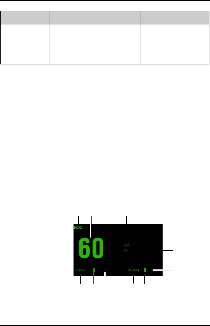
ECG Monitoring Monitoring with the TD60 at the CS
9 - 16 TMS60 Operator’s Manual
9.3.4 ECG Display
9.3.4.1 ECG Digital Area
The ECG digital area displays:
1. Area name
2. HR value
3. High HR alarm limit
4. Low HR alarm limit
5. Pauses threshold
6. Pauses per minute value
7. Pauses per minute label
8. PVCs threshold
9. PVCs per minute value
10. PVCs per minute label
ECG digital area
Filter Configures the ECG filter in all operating
modes.
■[Monitor]: use under normal
measurement conditions.
■[ST]: use when the ST monitoring is
applied.
Monitor, ST
Options Description Settings*
* The factory default settings are in bold.
123
4
5
6
7
8
910
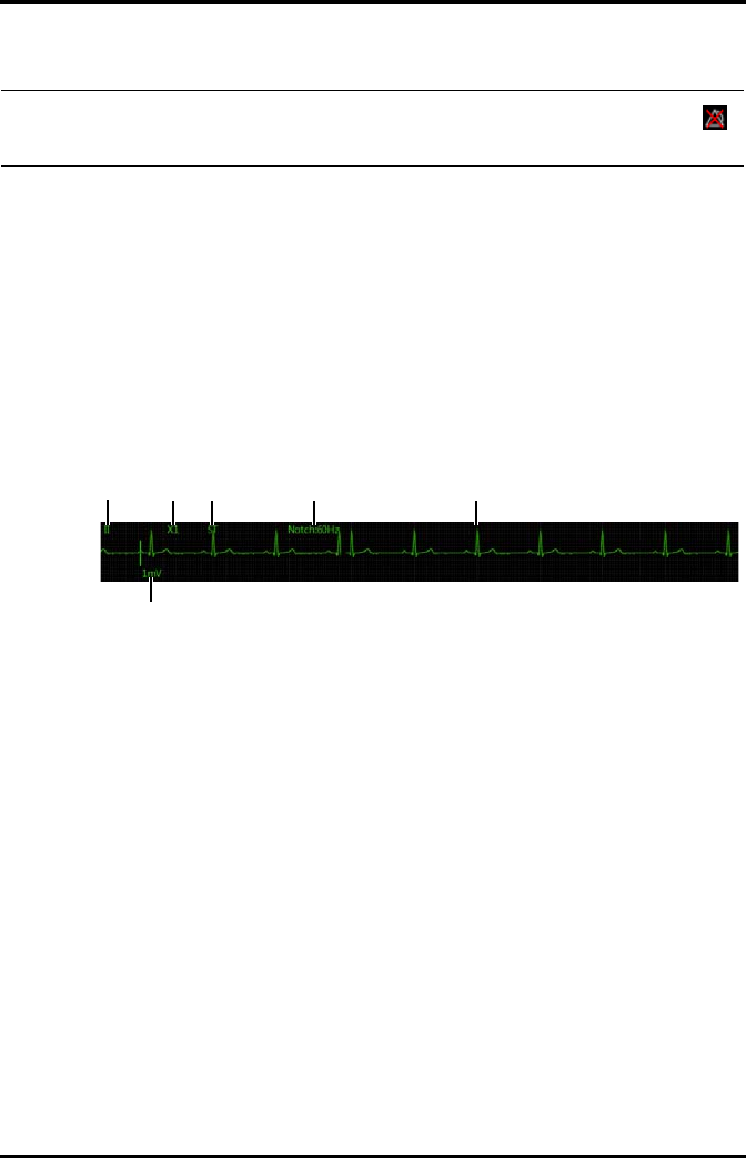
Monitoring with the TD60 at the CS ECG Monitoring
TMS60 Operator’s Manual 9 - 17
9.3.4.2 ECG Waveform Area
The ECG waveform area displays:
1. ECG Lead
2. ECG waveform size
3. ECG filter setting
4. Notch filter setting
5. ECG waveform
6. ECG scale
ECG waveform area
NOTE
•If the Activation State for HR, PVCs or Pauses alarm is set to [Off], the
symbol displays to the right of corresponding parameter.
1234 5
6
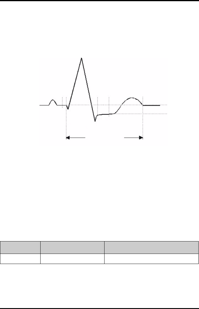
QT Monitoring Monitoring with the TD60 at the CS
9 - 18 TMS60 Operator’s Manual
9.4 QT Monitoring
A normal ECG waveform (as shown in the following figure) typically includes a sharp and
well defined QRS complexes with consistent spacing between R waves, and an ECG
baseline that is free of noise and artifact.
A normal ECG waveform (for QT monitoring)
The QT interval in an ECG lead is the time interval from the onset of the earliest deflec-
tion in the QRS complex to the end of the T wave. QT monitoring can assist in the detec-
tion of prolonged QT interval syndrome.
9.4.1 Measurement Limitations
■At least one measured V-lead must be available in order for the algorithm to
process QT.
■QT/QTc values are calculated with 3-leadwire or 5-leadwire ECG cables.
9.4.2 QT Settings
The following table lists the QT settings in the [QT Analysis] section of the [ECG] tab.
ST Point
J Point
ISO Point
R
T
QT Interval
P
Q
S
Options Description Settings*
QT Analysis Enables or disables QT analysis. On, Off
* The factory default settings are in bold.

Monitoring with the TD60 at the CS QT Monitoring
TMS60 Operator’s Manual 9 - 19
QT Computational
Formula
Configures the QTc formula used.
Bazett:
Fridericia:
Framingham:
Hodges:
QT Alarm Setup Configures the QT alarms. ■For details about the QT alarms limits, refer
to "Factory Default Parameter Alarm Limits"
on page 9 - 3 for details.
■For details about the QT alarms responses,
refer to "Factory Default Parameter Alarm
Settings" on page 9 - 5 for details.
■For Mindray algorithm, you can configure the QTc and ∆QTc alarm.
■For Mortara algorithm, you can configure the QTc alarms.
QT View Select to display the [QT View]
menu.
Refer to "QT View Menu (Only for Mindray ECG
Algorithm)" on page 9 - 20 for details.
This button is only available for the Mindray ECG algorithm.
Options Description Settings*
* The factory default settings are in bold.
QTc QT QTHR
60
-------------
12/
×=
QTc QT QTHR
60
-------------
13/
×=
QTc QT
154 1 60
QTHR
-------------
–
×+=
QTc QT
1.75
QTHR
60–()×+=
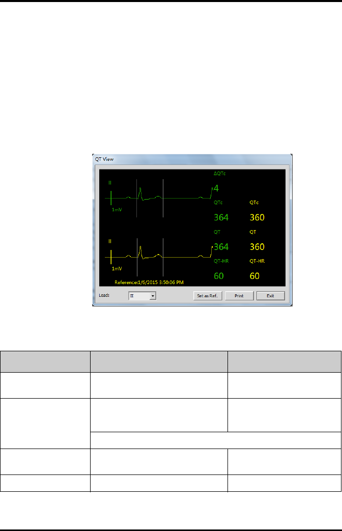
QT Monitoring Monitoring with the TD60 at the CS
9 - 20 TMS60 Operator’s Manual
9.4.3 QT View Menu (Only for Mindray ECG Algorithm)
In the [QT View] menu, you can view a snapshot of the real-time wave and to verify that
the QT algorithm detects correct Q and T points.
The [QT View] menu displays, as shown in the following figure:
◆The current waveform and parameter values display in green.
◆The template waveform and parameter values display in yellow.
◆The Q and T points are marked with a vertical line.
◆The ∆QTc value is equal to the current QTc value minus the template QTc
value.
QT View menu
Using the buttons described in the following table as desired.
Buttons Description Settings*
Lead Select the desired lead to display on the
[QT View] menu screen.
II, I, III, aVR, aVL, aVF, V
Set as Ref. Replaces the template waveform and QT/
QTc values with the current waveform and
QT/QTc values.
None
The QT template updated time displays at the bottom of the screen.
Print Prints the template and current wave-
forms, and QT/QTc values for all leads.
None
Exit Closes the [QT View] Menu. None
* The factory default settings are in bold.
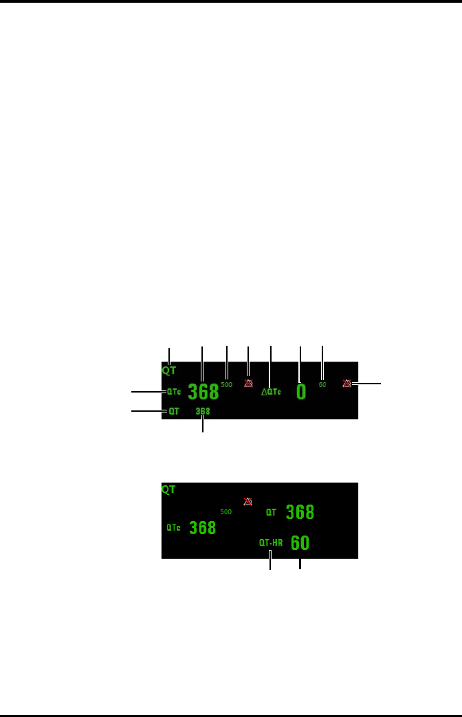
Monitoring with the TD60 at the CS QT Monitoring
TMS60 Operator’s Manual 9 - 21
9.4.4 QT Display
When [QT Analysis] is enabled, the QT digital area displays:
1. Area name
2. QTc value
3. High QTc alarm limit
4. Activation State Off symbol for QTc alarm
5. ∆QTc label
6. ∆QTc value
7. High ∆QTc alarm limit
8. Activation State Off icon for ∆QTc alarm
9. QT value
10. QT label
11. QTc label
12. QT-HR label
13. QT-HR value
Example QT digital area (for Mindray ECG algorithm)
Example QT digital area (for Mortara algorithm)
1234567
8
10
11
9
12 13
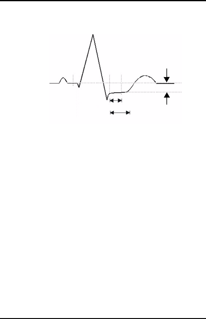
ST Monitoring Monitoring with the TD60 at the CS
9 - 22 TMS60 Operator’s Manual
9.5 ST Monitoring
A normal ECG waveform (for ST monitoring)
The ST segment of an ECG waveform (as shown in the above figure) represents the
period from the end of ventricular de-polarization, to the beginning of ventricular re-
polarization, or the end of the QRS complex (the J point) and the beginning of the T-
wave. ST Segment analysis is used to monitor the oxygen supply and the viability of the
heart muscle.
ST deviation is the vertical distance between the isoelectric (ISO) point level and signal
level at ST point.
The ISO point is located between the end of the P-wave and the onset of the QRS com-
plex. The ISO point provides the baseline for this measurement.
The ST point is a fixed distance from the J point at the end of the QRS complex. The ST
point can be configured to 40, 60, or 80 milliseconds past the J-point, independent of
the heart rate. By default, the ST point is positioned as follows:
■at 80 milliseconds for heart rates less than or equal to 120 beats per minute
■at 60 milliseconds for heart rates greater than 120 beats per minute
All available ECG leads are analyzed to measure deviations in the ST segment.
Selecting leads that contain the least amount of baseline flutter will improve measure-
ment accuracy, but accurate ST deviation measurement is dependent on the correct
location of the ISO and ST points.
■ST segment analysis calculates ST segment elevations and depressions for
individual leads and then displays them as numerics in the ST digital area.
■A positive value indicates ST segment elevation; a negative value indicates ST
segment depression.
R
PT
S
ST Point
J Point
ISO Point
40 to 80 msec
ST deviation
Depression or Elevation
ST Segment

Monitoring with the TD60 at the CS ST Monitoring
TMS60 Operator’s Manual 9 - 23
9.5.1 Measurement Limitations
■ST values may be affected by such factors as some drugs or metabolic and
conduction disturbances.
■Since ST is often calculated with a fixed delay from the J point, changes in heart
rate may affect ST.
■The ST algorithm has been tested for accuracy of the ST segment data. The
significance of the ST segment changes needs to be determined by a physician.
9.5.2 ST Settings
The following table lists the ST settings in the [ST Analysis] section of the [ECG] tab.
WARNING
•The ST algorithm has been tested for accuracy of the ST segment data.
The significance of the ST segment changes need to be determined by a
clinician.
Options or Buttons Description Settings*
ST Analysis Enables or disables ST analysis. On, Off
If [ST Analysis] is set to [On], the [Filter] option from the [Other Settings] menu
is automatically set to [ST].
Display ST Segments Select whether or not to display the ST
segments in the waveform area.
On, Off
ST Alarm Setup Configures the ST alarm settings. ■For details about the ST
alarms limits, refer to
"Factory Default Parameter
Alarm Limits" on page 9 - 3
for details.
■For details about the ST
alarms responses, refer to
"Factory Default Parameter
Alarm Settings" on page 9 - 5
for details.
Define ST Point Select to display the [Define ST Point]
menu.
Refer to "Adjusting ST Measure-
ment Points" on page 9 - 24 for
details.
This button is only available when [ST Analysis] is set to [On].
* The factory default settings are in bold.
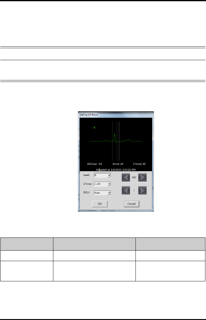
ST Monitoring Monitoring with the TD60 at the CS
9 - 24 TMS60 Operator’s Manual
9.5.3 Adjusting ST Measurement Points
The ISO and ST points need to be adjusted when you start monitoring and if the
patient’s heart rate or ECG morphology changes significantly. Exceptional QRS com-
plexes are not considered for ST-segment analysis.
1. In the [ST Analysis] section of the [ECG] tab, click [Define ST Point].
The [Define ST Point] menu displays, as shown in the following figure.
Define ST point menu
2. Adjust the parameter using the buttons described in the following table.
WARNING
•Always make sure that the ST measurement points are appropriate for
your patient.
Buttons Description Settings*
Lead Select the desired ECG lead. I, II, III, aVR, aVL, aVF, V
ST (ms) Based on the ms setting selected, moves
the ST point further or closer to the J point
in the ST template.
J+40, J+60, J+80, J+60/80
* The factory default settings are in bold.
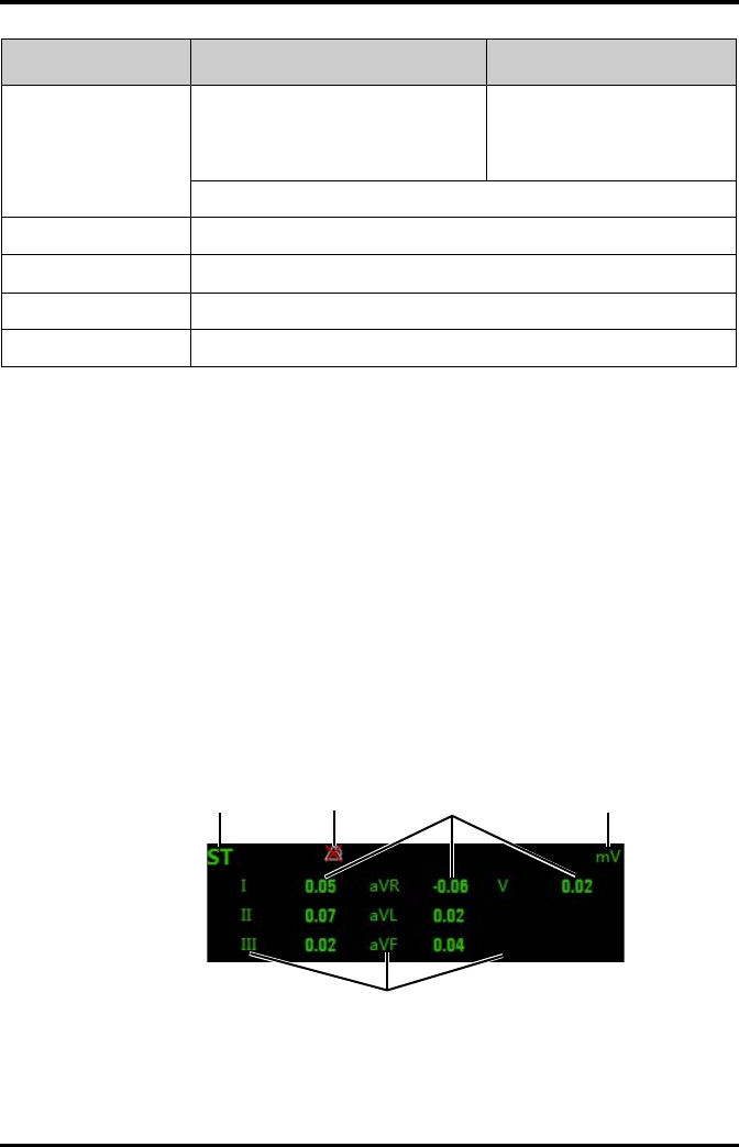
Monitoring with the TD60 at the CS ST Monitoring
TMS60 Operator’s Manual 9 - 25
3. Select the [OK] or [Cancel] button.
◆The [OK] button saves the settings and closes the menu.
◆The [Cancel] button closes the menu without saving the settings.
9.5.4 ST Display
When [ST Analysis] is enabled, the ST digital area displays:
1. Area name
2. Activation State Off icon for ST alarm
3. ST values
4. Units of measure
5. Lead identifier
Example 5-lead ST digital area
ISO/J Selecting [Auto] fixes the ISO and J/ST
points.
Selecting [Manual] allows the clinician to
manually adjust ISO and J/ST points.
Auto, Manual
For Mortara algorithm, the ISO and J/ST points can only be adjusted manually.
ISO left arrow If [ISO/J] is set to manual, the button adjusts the ISO reference line to the left.
ISO right arrow If [ISO/J] is set to manual, the button adjusts the ISO reference line to the right.
J left arrow If [ISO/J] is set to manual, the button adjusts the J reference line to the left.
J right arrow If [ISO/J] is set to manual, the button adjusts the J reference line to the right.
Buttons Description Settings*
* The factory default settings are in bold.
124
5
3
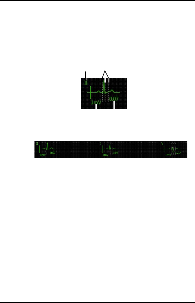
ST Monitoring Monitoring with the TD60 at the CS
9 - 26 TMS60 Operator’s Manual
9.5.5 ST Segment Display
When [Display ST Segments] is enabled, the ST segments display in the waveform area:
1. Lead identifier
2. ST markers (ISO, J/ST)
3. ST value
4. ECG scale
3-lead ST segment
5-lead ST segments
12
3
4

Monitoring with the TD60 at the CS Arrhythmia Monitoring
TMS60 Operator’s Manual 9 - 27
9.6 Arrhythmia Monitoring
9.6.1 Measurement Limitations
■Since the arrhythmia detection algorithm sensitivity and specificity is less than
100%, sometimes there may be some false arrhythmias detected and also some
true arrhythmia events may not be detected. This is especially true when the
signal is noisy.
■The ECG size and QRS width settings affect arrhythmia detection and heart rate
calculation sensitivity.
■If QRS amplitude is low, the monitor might not be able to calculate HR and false
asystole may occur.
■At the algorithm learning phase, arrhythmia detection may not be available.
Therefore, closely monitor the patient’s condition during the learning phase and
after the learning phase to allow the algorithm to reach optimal detection
performance.
9.6.2 Understanding the Arrhythmia Events
9.6.2.1 Mindray ECG Algorithm
WARNING
•The arrhythmia analysis program is intended to detect ventricular
arrhythmias. It is not designed to detect atrial or supraventricular
arrhythmias. It may incorrectly identify the presence or absence of an
arrhythmia. Therefore, a physician must analyze the arrhythmia infor-
mation with other clinical findings.
•Heart-rate reading may be affected by cardiac arrhythmias. Do not rely
entirely on heart rate alarms when monitoring patients with arrhyth-
mia. Always keep these patients under close surveillance.
Arrhythmia message Description Category
Asystole No QRS detected within the set time threshold in absence of ven-
tricular fibrillation or chaotic signal.
Lethal
arrhythmia
VFib/VTac A fibrillatory wave for 6 consecutive seconds.
A dominant rhythm of adjacent Vs and a HR > the V-Tac HR limit.
VTac The consecutive PVCs ≥ Vtac PVCs limit, and the HR ≥ the Vtac rate
limit.

Arrhythmia Monitoring Monitoring with the TD60 at the CS
9 - 28 TMS60 Operator’s Manual
Vent. Brady The consecutive PVCs ≥ the Vbrd threshold and the ventricular HR <
the Vbrd Rate threshold.
Lethal
arrhythmia
Extreme Tachy The heart rate is equal to or greater than the extreme tachycardia
limit.
Extreme Brady The heart rate is equal to or less than the extreme bradycardia limit.
PVCs/min PVCs/min exceeds high limit. Nonlethal
arrhythmia
R on T R on T detected in normal heartbeats.
Run PVCs More than 2 consecutive PVCs.
Couplet Paired PVCs detected in normal heartbeats.
PVC One PVC detected in normal heartbeats.
Vent. Rhythm The consecutive PVCs ≥ the Vbrd PVCs limit, and the HR ≥ Vbrd Rate
limit but < the Vtac Rate limit.
Bigeminy A dominant rhythm of N, V, N, V, N, V.
Trigeminy A dominant rhythm of N, N, V,N, N, V, N, N, V.
Tachy The average heart rate is equal to or greater than the tachycardia
limit.
Brady The average heart rate is equal to or less than the bradycardia limit.
Pacer Not Pacing No pace pulse detected for 1.75 x average R-to-R intervals following
a QRS complex (for paced patients only).
Pacer Not Capture No QRS complex detected for 300 milliseconds following a pace
pulse (for paced patients only).
Missed Beat No beat detected for 1.75 x average R-R interval for HR <120, or
No beat for 1 second with HR > 120 (for non-paced patients only), or
No beat detected for more than the set pause threshold.
Multif. PVC Multiform PVCs detected in Multif. PVC's Window (which is adjust-
able).
Nonsus. Vtac The consecutive PVCs < the Vtac PVCs limit but > 2, and HR ≥ the
Vtac Rate limit.
Pause No QRS detected within the set time threshold of pause.
AFib Continuously detect that the RR intervals of normal sinus beats
irregular and no P wave of normal sinus beats.
Irr. Rhythm Consistently irregular rhythm.
Pauses/min The number of pauses detected per minute.
Arrhythmia message Description Category

Monitoring with the TD60 at the CS Arrhythmia Monitoring
TMS60 Operator’s Manual 9 - 29
9.6.2.2 Mortara ECG Algorithm
Arrhythmia message Description Category
Asystole No QRS complex detected within the set time threshold (in absence
of ventricular fibrillation or chaotic signals).
Lethal
arrhythmia
VFib Ventricular fibrillation occurs and persists for 6 seconds.
VTac Ventricular HR is greater or equal to the preset threshold and the
number of consecutive PVCs is greater than the preset threshold.
Extreme Tachy The heart rate is equal to or greater than the extreme tachycardia
limit.
Extreme Brady The heart rate is equal to or less than the extreme bradycardia limit.
PVCs/min PVCs/min exceeds high limit. Nonlethal
arrhythmia
R on T R on T is detected.
Run PVCs More than 2 consecutive PVCs.
Couplet Paired PVCs are detected.
Vent. Rhythm Ventricular HR is less than the preset threshold and the number of
PVCs is greater than or equal to 3.
Bigeminy A dominant rhythm of N, V,N, V, N, V.
Trigeminy A dominant rhythm of N, N, V,N, N, V, N, N, V.
Tachy The HR is greater than the set tachycardia high limit.
Brady The HR is less than the set bradycardia low limit.
Pacer Not Pacing No pace pulse detected for (60×1000/pace rate +90) milliseconds
following a QRS complex or a pacer pulse (for paced patients only).
Pacer Not Capture No QRS complex detected for 300 milliseconds following a pace
pulse (for paced patients only).
Multif. PVC More than 2 PVCs of different forms occur in the predefined search
window (3-31).
Pause No beat detected for 1.75x average R-R interval for HR <120, or
No beat for 1 second with HR >120 (for non-paced patients only), or
No beat detected for more than the set pause threshold.
Irr. Rhythm Consistently irregular rhythm
Pauses/min The number of pauses detected per minute.

Arrhythmia Monitoring Monitoring with the TD60 at the CS
9 - 30 TMS60 Operator’s Manual
9.6.3 Arrhythmia Settings
The following table lists the arrhythmia settings in the [Arrhythmia Analysis] section of
the [ECG] tab.
9.6.4 Relearning
A relearn can be done for arrhythmia, ST analysis, or for both simultaneously.
The TD60 initiates the learning process for ST or Arrhythmia analysis after any of the fol-
lowing:
■TD60 power-up
■Return to normal monitoring from the Standby mode
■Enabling ST or Arrhythmia analysis
■The lead has been changed in ECG 1 waveform (3 lead only)
■Patient size changes
■Selecting the Relearn button in the [Arrhythmia Analysis] section
Selecting the Relearn button in the [Arrhythmia Analysis] section is recommended
after one or more of the following:
■ECG electrodes have been repositioned
■Eight hours have passed since the last relearn
■Significant changes occurred to the patient QRS complex
Options or Buttons Description Settings*
Arrhythmia Alarms Configures the arrhythmia alarm settings. Refer to "Factory Default Arrhyth-
mia Alarm Settings" on page 9 - 6
for details.
Relearn Enables an arrhythmia relearning. Refer to "Relearning" on page 9 -
30 for details.
QRS Threshold Settings Configures the QRS threshold. Refer to "Configuring the QRS
Threshold" on page 9 - 31 for
details.
NOTE
•ST Analysis must be turned on before it will relearn.

Monitoring with the TD60 at the CS Arrhythmia Monitoring
TMS60 Operator’s Manual 9 - 31
■Significant changes occurred to the patient ECG rhythm
■A clinician has observed clinically questionable arrhythmia calls
■“Learning” occurred during a Leads Off condition
9.6.5 Configuring the QRS Threshold
The minimum detection threshold is approximately 0.16 mV. In case the P waves are very
tall, one might consider moving the minimum QRS detection threshold up to be above
the level of the P waves, so events like ventricular standstill are not missed.
Two horizontal lines (one below and one above the baseline) appear on the screen.
These represent the current minimum detection threshold on the positive and negative
sides of the baseline so manual adjustment for both positive and negative going QRS's
can be made. Using the commands provided, move the minimum detection threshold
up or down to ensure it is above the level of the P waves but below the peak of the R-
wave. Since the P-wave height could vary a little from beat to beat, do not set the hori-
zontal line representing the minimum detection threshold at or barely above the level of
the peak of the P wave. Ensure that it is at least one or two millimeters above the peak of
the P wave but below the peak of the R-wave.
1. In the [Arrhythmia Analysis] section of the [ECG] tab, click [Minimum QRS
Threshold].
The [Minimum QRS Threshold] menu displays, as shown in the following figure.
CAUTION
•Initiate ECG relearning only during periods of normal rhythm and when
the ECG signal is relatively noise-free. If ECG learning takes place during
ventricular rhythm, the ectopics may be incorrectly learned as the nor-
mal QRS complex. This may result in missed detection of subsequent
events of V-Tach and V-Fib.
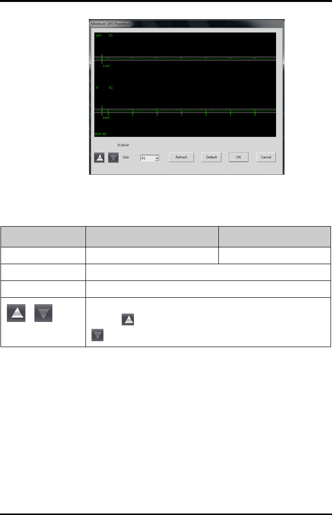
Arrhythmia Monitoring Monitoring with the TD60 at the CS
9 - 32 TMS60 Operator’s Manual
Minimum QRS Threshold menu
The current waveform displays the data of previous eight seconds. Use the buttons
described in the following table as desired.
2. Select the [OK] or [Cancel] button.
◆Once the threshold is in the desired position, select the [OK] button to save
the settings and close the menu.
◆To quit adjusting the threshold, select the [Cancel] button to close the menu
without saving the settings.
Buttons Description Settings*
Gain Select the desired ECG waveform size. X1, X2, X4
Refresh Displays the real-time waveform.
Default Automatically sets the default threshold: 0.16 mV.
or
Manually adjust the minimum QRS detection threshold.
Select the button to move the threshold line above the P wave, or select the
button to move the threshold line down closer to the P wave.
* The factory default settings are in bold.

Monitoring with the TD60 at the CS SpO2 Monitoring
TMS60 Operator’s Manual 9 - 33
9.7 SpO2 Monitoring
At the CS, you can view and change the SpO2 settings in the [SpO2] tab of the [Parame-
ter Setup] menu.
For details about the [Parameter Setup] menu, refer to the BeneVision Central Station
Operator’s Manual (P/N 046-005011-00).
9.7.1 Measurement Limitations
Refer to "Measurement Limitations" on page 8 - 2 for details.
9.7.2 SpO2 Settings
The following table lists the SpO2 settings in the [SpO2] tab.
Options Description Settings*
Activation State Configures whether or not to enable the
SpO2 alarm.
On, Off
Alarm Priority Configures the SpO2 alarm levels. High, Med
Record on Alarm Selects whether or not to activate the
recorder when an SpO2 alarm is triggered.
On, Off
Sweep Speed Configures the SpO2 waveform sweep
speed.
6.25 mm/s, 12.5 mm/s, 25.0 mm/
s, 50.0 mm/s
Desat Limit Activation
State
Configures whether or not to enable the
SpO2 Desat alarm.
On, Off
Sensitivity
(Masimo only)
The option is not configurable. The option setting is synchronous with the set-
ting at the TD60. Refer to "Configuring the SpO2 Setup" on page 8 - 5.
SpO2 High Limit (%) Configures the SpO2 high alarm limit. (Low limit + 1) to 100
The default is 100.
SpO2 Low Limit (%) Configures the SpO2 low alarm limit. 0 to (high limit - 1)
The default is 90.
PR High Limit (bpm) Configures the PR high alarm limit. (Low limit + 2) to 300
The default for adult is 120.
The default for pediatric is 160.
PR Low Limit (bpm) Configures the PR low alarm limit. 18 to (high limit - 2)
The default for adult is 50.
The default for pediatric is 75.
* The factory default settings are in bold.
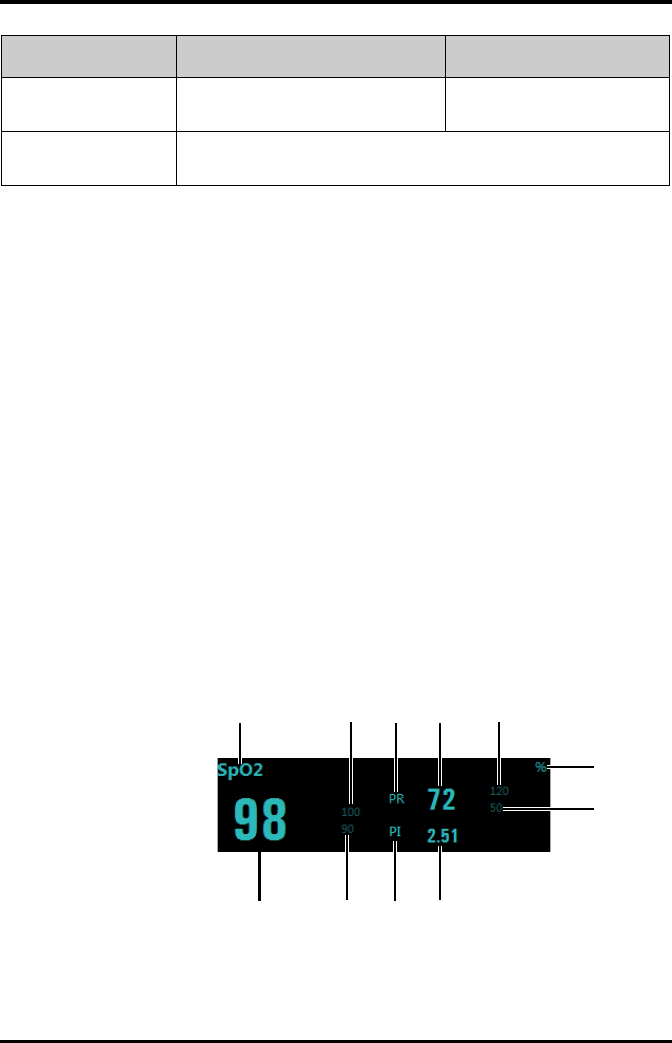
SpO2 Monitoring Monitoring with the TD60 at the CS
9 - 34 TMS60 Operator’s Manual
9.7.3 SpO2 Display
9.7.3.1 SpO2 Digital Area
The SpO2 digital area displays:
1. Area name
2. High SpO2 alarm limit
3. PR label
4. PR value
5. High PR alarm limit
6. SpO2 unit of measure
7. Low PR alarm limit
8. Masimo perfusion index value
9. PI label
10. Low SpO2 alarm limit
11. SpO2 value
Masimo SpO2 digital area
Desat Limit (%) Configures the SpO2 Desat low limit. 0 to 100
The default is 80.
Averaging
(Masimo only)
The option is not configurable. The option setting is synchronous with the set-
ting at the TD60. Refer to "Configuring the SpO2 Setup" on page 8 - 5 for details.
Options Description Settings*
* The factory default settings are in bold.
1234 5
6
7
8910
11
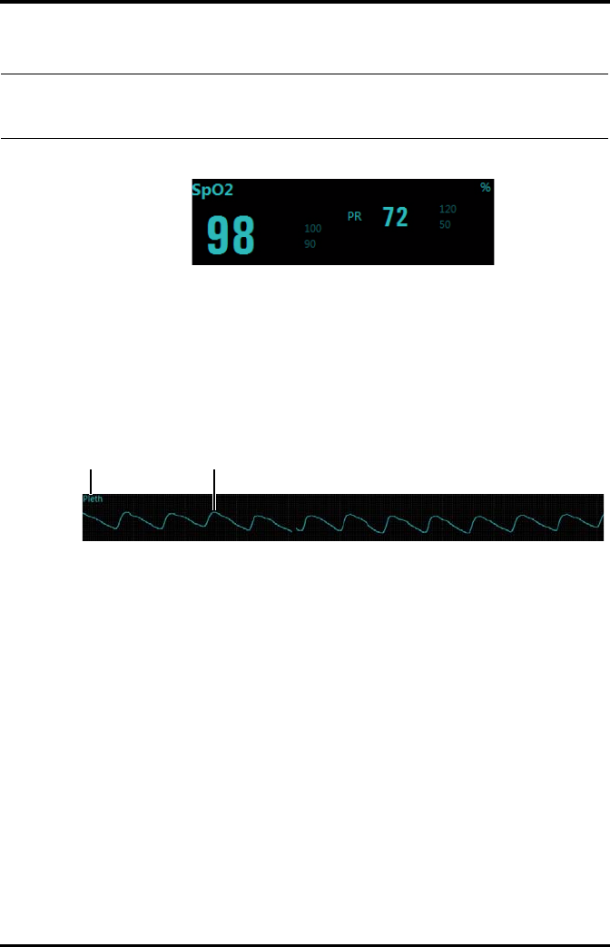
Monitoring with the TD60 at the CS SpO2 Monitoring
TMS60 Operator’s Manual 9 - 35
Nonin SpO2 digital area
9.7.3.2 SpO2 Waveform Area
The SpO2 waveform area displays:
1. Area name
2. Pleth waveform
SpO2 waveform area
NOTE
•When [HR Source] of the [ECG] tab is set to [Both], the PR value displays
on the SpO2 digital area.
12

SpO2 Monitoring Monitoring with the TD60 at the CS
9 - 36 TMS60 Operator’s Manual
This page intentionally left blank.


Introduction Configuring the TD60
10 - 2 TMS60 Operator’s Manual
10.1 Introduction
This TD60 Maintenance menu provides access to the system settings such as location,
device name, alarm settings, quick keys, screen lock, and password updates. Entering
this menu requires a password.
10.2 Maintenance Menu
The [Maintenance] menu contains the following submenus:
■General
■Alarms
■Quick Keys
■Defaults
■Screen Lock
■Edit Passcodes
■Device Name
■Demo Mode
■Service
10.2.1 Entering the Maintenance menu
1. In the main menu, tap [Maintenance].
2. Input the maintenance password.
3. Tap [Accept] to enter the [Maintenance] menu.
10.2.2 Configuring the General Menu
Select [General] to configure the display auto off, language, location, notch filter, ECG
lead labeling, SpO2 module, SpO2 tone, and enable or disable ECG calibration.
1. In the [Maintenance] menu, tap [General].
The current setting displays to the right of the option.
2. Select the options described in the following table.
Options Description Settings*
Display Auto Off Configures the time for display auto off. 1 min, 2 min, 5 min, 15 min 30
min, Off
Language Configures the system language. ENGLISH, FRENCH
* The factory default settings are in bold.
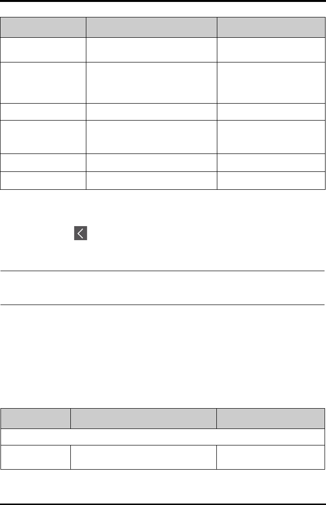
Configuring the TD60 Maintenance Menu
TMS60 Operator’s Manual 10 - 3
3. Tap to exit the [General] menu.
10.2.3 Configuring the Alarms Menu
Select [Alarms] to configure the alarm tone, reminder tone, reminder interval, minimum
alarm volume, and technical alarm priority.
1. In the [Maintenance] menu, tap [Alarms].
The current setting displays to the right of the option.
2. Select the options described in the following table.
Location Changes the hospital and department
names.
N/A
Notch Filter Configures the ECG Notch filter. This
option is used to filter out AC line noise
from the ECG waveform.
50 Hz, 60 Hz, Off
The default is 50 Hz when the
device is not configured for the
US.
ECG Lead Labeling Changes the ECG lead labeling. AHA, IEC
Calibrate ECG Enables or disables the ECG verification. On, Off
Refer to "Verifying the ECG at the
TD60" on page 14 - 4 for details.
SpO2 Module Changes the SpO2 module. Masimo, Nonin
SpO2 Tone Configures the SpO2 tone. Mode 1, Mode 2
Options Description Settings*
* The factory default settings are in bold.
NOTE
•Mindray recommends the same SpO2 tone mode be used for the device
within a monitoring area.
Section & Options Description Settings*
Sounds
Style Allows an authorized user to set the alarm tone
pattern.
ISO, Mode 1, Mode 2
* The factory default settings are in bold.
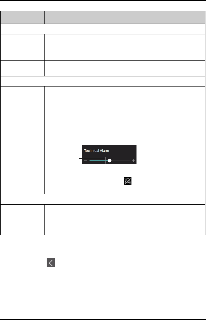
Maintenance Menu Configuring the TD60
10 - 4 TMS60 Operator’s Manual
3. Tap to exit the [Alarms] menu.
Timeout
Reminder Tone Allows an authorized user to enable or disable
the reminder tone.
If the alarm tone is turned off, enabling this set-
ting can issue a periodic reminder tone.
On, Off
Reminder Interval Allows an authorized user to configure the
intervals between the alarm tones.
1 min, 2 min, 3 min, 5 min, 10 min
Minimum Alarm Volume
Technical Allows an authorized user to set the minimum
technical alarm volume.
The minimum technical alarm volume defines
the minimum value you can set for the techni-
cal alarm volume.
For example:
If the minimum technical alarm volume is set to
5, the minimum value you can set for the tech-
nical alarm volume in the [Audio Volume]
menu is 5 (as shown in the following figure).
If the minimum technical alarm volume is set to
Off, and the technical alarm volume can be set
to 0, the alarm sound is turned off and the
symbol appears on the screen.
Off, 1, 2, 3, 4, 5, 6, 7, 8, 9, 10
Technical Alarm Priority
ECG Lead Off Allows an authorized user to configure the
alarm level.
Low, Medium, High
SpO2 Sensor Off Allows an authorized user to configure the
alarm level.
Low, Medium, High
Section & Options Description Settings*
* The factory default settings are in bold.
Minimum value
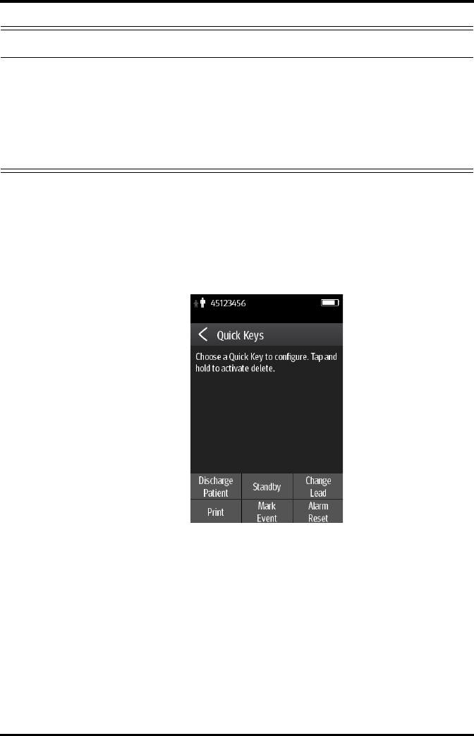
Configuring the TD60 Maintenance Menu
TMS60 Operator’s Manual 10 - 5
10.2.4 Quick Keys Menu
10.2.4.1 Changing the Quick Keys
1. In the [Maintenance] menu, tap [Quick Keys].
The [Quick Keys] configuration menu displays.
2. From the quick keys area at the bottom of the screen, tap a quick key you want to
configure.
A list of option displays.
WARNING
•When the technical alarm audio volume is set to alarm sound and the
alarm sound is turned off, the TD60 will not enunciate technical alarms
when they occur. Be careful when turning off the alarm volume.
•Do not rely exclusively on the audible alarm system for monitoring.
Adjustment of alarm volume to a low level may result in a hazard to the
patient. Always keep the patient under close surveillance.
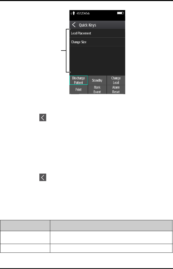
Maintenance Menu Configuring the TD60
10 - 6 TMS60 Operator’s Manual
3. Tap the desired option from the list of options to configure the selected quick key.
4. Repeat steps 2 to 3 to configure other quick keys, if needed.
5. Tap to exit the [Quick Keys] menu.
10.2.4.2 Deleting a Quick Key
1. From the quick keys area at the bottom of the [Quick Keys] menu, press and hold
the desired quick key for two seconds, and then release it.
The quick key background turns to red and displays [Delete].
2. Tap [Delete].
The quick key is removed from the quick keys area, and the area displays [Not
Used].
3. Tap to exit the [Quick Keys] menu.
10.2.5 Configuring the Defaults Menu
The [Defaults] menu allows an authorized user to manage the system configurations.
1. In the [Maintenance] menu, tap [Defaults].
2. Select the options described in the following table.
A list of options
Options Description
Save Departmental Defaults Allows an authorized user to save the current device settings for the selected
patient category.
Export Device Settings Copies the user configuration to the external device.
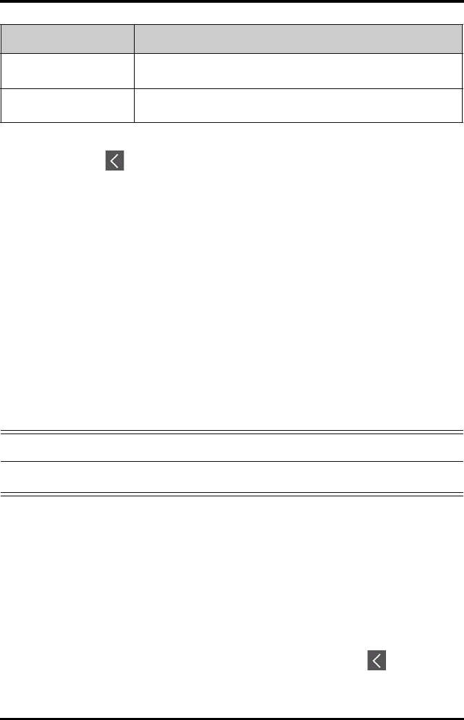
Configuring the TD60 Maintenance Menu
TMS60 Operator’s Manual 10 - 7
3. Tap to exit the [Defaults] menu.
10.2.6 Transferring a Configuration
The TD60 is capable of configuring multiple devices through one export operation via a
wireless interface.
To transfer the configuration from the TD60 unit to an external device:
1. In the [Maintenance] menu of an external device, tap [Defaults] → [Import
Device Settings] to enter the settings import mode.
2. In the [Maintenance] menu of the TD60 unit, tap [Defaults] → [Export Device
Settings] to enter the [Export Device Settings] menu.
The discovered external devices are listed in the [Export Device Settings] menu.
3. Select the desired external devices by tapping the check box.
4. Tap [Export] to start exporting the TD60 unit configuration.
The selected external devices screen will shortly display the “Downloading device
settings” message.
■On the external devices if an import is successful, the external device will display
the “Download complete.” message, and after 10 seconds return to the [Defaults]
menu. On the TD60 unit, the status for the external device will display the
“Complete” message.
■On the external device if the import fails, the external device will display the
“Import attempt failed.” message. On the TD60 unit, the status for the failed
external device will display the “Failure” message and remain in the list.
The user has two options when a failure occurs:
◆To stop the import from the external device, tap the icon to exit the
[Import Device Settings].
Import Device Settings Copies the settings from the external device to theTD60 unit. Refer to "Trans-
ferring a Configuration" on page 10 - 7 for details.
Restore Factory Defaults Allows an authorized user to reestablish the original database power up
settings to factory default values.
Options Description
WARNING
•Do not power off the devices during the download process.

Maintenance Menu Configuring the TD60
10 - 8 TMS60 Operator’s Manual
◆To retry the import from the TD60 unit, tap the external device which is dis-
playing the [Failure] message, tap the [Retry] button to restart the transfer.
You may need to repeat the retry operation several times until the transfer is
successful.
10.2.7 Screen Lock Menu
10.2.7.1 Understanding the Screen Lock Mode
There are two modes of being able to lock the screen to assist in preventing unauthor-
ized use. Each mode allows the user access to certain features of the product without
entering a passcode. When the correct passcode is entered, all features are available.
■Locked Mode Features:
◆Main screen and main menu are not accessible without passcode entry.
◆The message area is still viewable.
◆Hardkeys are enabled.
■View Only Features:
◆Upon powering up, the main screen will be displayed after the new patient
choice is made.
◆Main Screen is accessible without passcode entry.
◆The [System Info] menu is accessible by tapping the battery symbol on the
main screen.
◆The [Lead Placement] menu is accessible by tapping an “ECG Lead Off”
message in the message area.
◆Ability to change display orientation.
◆Hardkeys are enabled.
10.2.7.2 Setting the Screen Lock
The initial enabling of screen lock mode requires a passcode to be entered immediately
as follows:
1. In the [Maintenance] menu, tap [Screen Lock] to select a screen lock mode.
2. Enter a new passcode for the screen lock.
After the passcode is entered, the screen exits the passcode setup menu. The
selected lock mode displays to the right of [Screen Lock].

Configuring the TD60 Maintenance Menu
TMS60 Operator’s Manual 10 - 9
10.2.7.3 Changing the Current Screen Lock Passcode
1. In the [Maintenance] menu, tap [Screen Lock].
2. Tap [Screen Lock Passcode].
3. Input the current password.
4. Input and verify the new password
10.2.8 Changing the Passwords
1. In the [Maintenance] menu, tap [Edit Passwords].
◆Tap [Maintenance Password] and follow the on-screen instructions to
change the maintenance password.
◆Tap [Service Password] and follow the on-screen instructions to change the
service password.
2. Tap the icon to exit the [Edit Passwords] menu.
10.2.9 Changing the Device Name
1. In the [Maintenance] menu, tap [Device Name].
2. Use the on-screen keyboard to input the device name.
3. Tap [Accept] to save the setting and exit the [Device Name] menu.
10.2.10 Demo Mode
Allows an authorized user to choose a demonstration mode for in-servicing staff or test-
ing product features.
10.2.11 Service Menu
Allows an authorized user access to the passcode protected Service menu.
NOTE
•Do not set the same device name for the TD60s.

Maintenance Menu Configuring the TD60
10 - 10 TMS60 Operator’s Manual
This page intentionally left blank.

TMS60 Operator’s Manual 11 - 1
11 Battery
Introduction...............................................................................................................11-2
Safety............................................................................................................................11-2
Installing the Battery ..............................................................................................11-3
Checking the Battery Charge Status.................................................................11-4
Removing the Battery ............................................................................................11-4
Charging the Rechargeable Lithium-ion Battery .........................................11-5
Storing the Batteries...............................................................................................11-6
Maintaining the Rechargeable Lithium-ion Battery....................................11-7
Disposing of the Batteries.....................................................................................11-8

Introduction Battery
11 - 2 TMS60 Operator’s Manual
11.1 Introduction
The TD60 can be powered by a lithium-ion rechargeable battery or AA batteries. This
chapter provides instructions on how to use, maintain, and dispose of the batteries.
11.2 Safety
SE
WARNING
•Keep the batteries out of children’s reach.
•Keep the batteries in their original package until you are ready to use
them.
•The battery compartment should be closed during defibrillation.
•Only use specified AA batteries or rechargeable lithium-ion battery to
power the TD60. Other power supply may cause damage to the
equipment or lead to body injury.
•While installing AA batteries, do not apply reverse polarity.
•Only use specified fresh AA batteries. Using other AA batteries can give
unacceptable performance.
•Do not mix old and new AA batteries.
•Only use specified rechargeable lithium-ion battery. Unspecified
lithium-ion battery can give unacceptable performance.
•Use caution when handling the rechargeable lithium-ion battery.
Misuse or abuse may cause bodily injury or device damage.
◆Do not short circuit. Take care that the terminals do not contact
metal or other conductive materials during transport and storage.
◆Do not crush, drop or puncture the battery. Mechanical abuse can
lead to internal damage and internal short circuits. If a battery has
been dropped or banged against a hard surface, whether damage
is externally visible or not, remove the battery from use and dis-
pose of it properly.
◆Do not incinerate batteries or expose them to temperatures above
60°C (140°F).
•The rechargeable lithium-ion batteries should be charged in the
specified central charger.

Battery Installing the Battery
TMS60 Operator’s Manual 11 - 3
11.3 Installing the Battery
Refer to "Installing the Batteries" on page 3 - 5 for details.
WARNING
•If a battery shows signs of damage or signs of leakage, replace it
immediately. Use caution in removing the battery. Avoid contact with
skin. Refer to qualified service personnel.
•Some failure conditions, such as short circuits, can cause a battery to
overheat during using. High temperature can cause burns to the patient
or user. If the device becomes too hot to the touch, remove it from the
patient and place aside until it cools. Then remove the battery from the
device, and contact your service personnel to identify the cause of
overheating.
•Replace the battery immediately once the “Critically Low Battery” alarm
message displays. Replace the battery in time once the “Low Battery”
alarm message displays. If those conditions are not corrected, device
shutdown and cessation of monitoring will result.
•To eliminate the risk of electrical shock or burn, do not carry loose
batteries on your person, such as placing the battery in clothing
pockets.
CAUTION
•Remove the battery before transporting the device or if the device is not
in use or is being stored.
•AA batteries should be removed from the device at the end of the
battery’s useful life to prevent leakage. In case of battery leakage, use
caution to remove the batteries and clean the battery compartment.
Install fresh AA batteries and check if the TD60 can power on properly. If
the TD60 fails to power on, contact your service personnel.

Checking the Battery Charge Status Battery
11 - 4 TMS60 Operator’s Manual
11.4 Checking the Battery Charge Status
The battery symbol displaying on the top of main screen indicates the battery charge
status. The white part ( ) indicates the remaining battery charge.
11.5 Removing the Battery
1. Lift up the lithium-ion battery pack or AA battery tray at the bottom of the TD60.
NOTE
•If the “Low Battery” or “Critically Low Battery” alarm occurs, the TD60
turns off the audio, the screen display the “Local Audio Off” message,
and the screen brightness turns dimmer.
CAUTION
•Some failure conditions, such as short circuits, can cause a battery to
overheat during using. High temperature can cause burns to the patient
or user. If the device becomes too hot to the touch, remove it from the
patient and place aside until it cools. Then remove the battery from the
device, and contact your service personnel to identify the cause of
overheating.
•Avoid scraping the metal contact in the battery compartment while
removing the lithium-ion battery pack or AA battery frame. Otherwise,
the broken contact will affect the power supply performance.
•Remove the battery before transporting the device or if the device is not
in use or is being stored.
NOTE
•Retain the ECG cable and SpO2 module with the device while removing
the battery.

Battery Charging the Rechargeable Lithium-ion Battery
TMS60 Operator’s Manual 11 - 5
2. Remove the lithium-ion battery pack or AA battery tray from the TD60.
11.6 Charging the Rechargeable Lithium-ion Battery
Use the central charger to charge the lithium-ion batteries. The central charger can
charge 10 lithium-ion batteries at one time. For details about the central charger, refer to
the BeneVision Central Charger Operator’s Manual (P/N 046-007059-00).
WARNING
•Only use the specified central charger to charge to the lithium-ion
batteries designated by Mindray.
•Only use the approved power cord with the grounded mains plug to
firmly connect the central charger to a grounded AC mains socket. Never
refit the mains plug to fit an ungrounded AC mains socket.
•Do not use the Multiple Portable Socket Outlets (MPSO) or AC mains
extension cords. Use an IEC 60601-1 approved isolation / separation
transformer, otherwise, it may result in leakage current. Insure that the
sum of the individual ground leakage currents does not exceed the
allowable limits.
•Do not place any shield object (such as cloth or paper) to cover the
central charger or batteries, and keep ventilated while charging the
lithium-ion batteries.
•Do not connect other devices to the power supply system.
•Do not use the central charger to charge the lithium-ion batteries in high
temperature above 40°C.
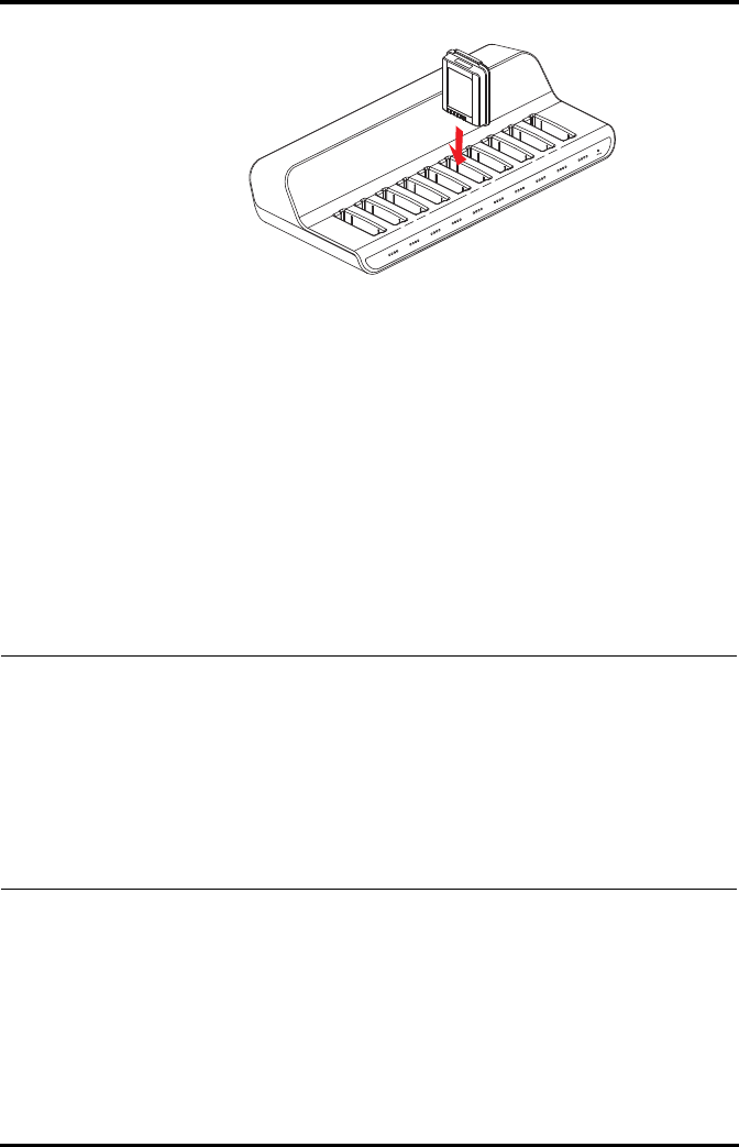
Storing the Batteries Battery
11 - 6 TMS60 Operator’s Manual
11.7 Storing the Batteries
11.7.1 Storing Rechargeable Lithium-ion Battery
When storing batteries, make sure that the battery terminals do not come into contact
with metallic objects.
If you need to store the batteries for an extended period of time, place the batteries in a
cool, dry place (ideally at 15°C or 60°F) with a partial charge of about 50% capacity (two
LEDs illuminated). Storing batteries in a cool place can slow the aging process.
Stored batteries should be charged to about 50% of their capacity every six months. The
battery should be fully charged prior to first use.
11.7.2 Storing AA Batteries
If you remove undepleted AA batteries from the TD60 and need to store the batteries,
keep the batteries together as a set for later re-use so that all batteries will have the same
level of remaining power.
Do not store disposable AA batteries by leaving the batteries in the incorrect polarity
position in the TD60.
NOTE
•Remove the lithium-ion battery from the device if the device is not used
for a prolonged time (for example, several weeks), and keep the device
in clean place to avoid the dust or liquid entering the battery
compartment.
•Storing batteries at high temperatures for an extended period of time
will significantly shorten their life expectancy.
•Do not store the batteries in an environment above 60°C (122°F) or
lower than -20°C (4°F).

Battery Maintaining the Rechargeable Lithium-ion Battery
TMS60 Operator’s Manual 11 - 7
11.8 Maintaining the Rechargeable Lithium-ion Battery
Take care of the rechargeable lithium-ion battery once you receive a new battery for use.
The following table describes the battery maintenance activities and recommended
frequency.
The lifetime of a lithium-ion battery depends on the frequency and duration of use. With
good maintenance, the useful life is approximately four years or 500 complete charge-
discharge cycles. In addtion, experience indicates that the incidence of failure may
increase with battery service life due to the accumulated stresses of daily use. Therefore,
Mindray strongly recommend that lithium-ion battery should be replaced after two
years or 300 complete charge-discharge cycles. Using the outdated battery may cause
the device abnormity and unacceptable performance.
The age of a lithium-ion battery begins at the date of manufacture. The date of
manufacture is listed on the rear of the battery.
NOTE
•Replace the AA battery frame on the battery compartment after
removing the AA batteries.
Activity Recommended Frequency
Visual inspection Before installing a battery in the TD60.
Charge the battery Upon receipt, after use, a “Low Battery” or “Critically Low Bat-
tery” alarm occurs.
To optimize performance, a fully or almost fully discharged
battery must be charged immediately.
Clean the battery At each patient discharge, or in case that the battery is
exposed to contaminants.
Do not clean the battery connector during the cleaning.
Charge stored battery to at
least 40% of the battery
capacity.
Every six months if the TD60 is not in use for an extended
period of time.
Dispose of the battery When the “Battery Maintenance Required” alarm message
displays on the TD60.

Disposing of the Batteries Battery
11 - 8 TMS60 Operator’s Manual
11.9 Disposing of the Batteries
11.9.1 Disposing of the Rechargeable Lithium-ion Battery
Discard the lithium-ion battery in the following situations:
■The battery has visual signs of damage.
■The battery fails.
■The battery is aged and its runtime significantly less than the specification.
■The battery has been used for more than two years or 500 complete charge-dis-
charge circles.
Discharge the battery and insulate the terminals with tape before disposal. Properly
dispose of the batteries according to local regulations.
11.9.2 Disposing of the AA Batteries
The batteries may be subject to local regulations regarding disposal. Dispose of batteries
in approved containers. Follow local regulations, if any, to recycle the batteries.
NOTE
•The battery capacity degrades as using time and number of recharge
cycles.Toward the end of its useful life, the battery capacity may be
reduced by 20% to 25%. If the reduced battery life is unacceptable for
your device, Mindray recommends the battery be replaced.

TMS60 Operator’s Manual 12 - 1
12 Troubleshooting
General Problems ....................................................................................................12-2
Physiological Alarm Messages at the CS .........................................................12-3
Technical Alarm Messages at the TD60 ...........................................................12-5

General Problems Troubleshooting
12 - 2 TMS60 Operator’s Manual
12.1 General Problems
The following table lists the problems that are likely to occur. If the problem persists after
corrective actions have been taken, contact your service personnel.
12.1.1 Troubleshooting Tools
■Telemetry Receiver (RC60)
■TD60
■Central Station (CS)
12.1.2 Problem List
Symptom Possible cause Solution
No RF Signal (The RC60
does not receive valid
data for consecutive 5
seconds)
1. The TD60 battery charge is to be
depleted.
2. The patient is out of the antenna
array coverage area.
3. The TD60 is not connected with
the ECG leadwire.
1. Check if the TD60 battery charge
is depleted.
2. Check if the patient is out of the
coverage area.
3. Check if the TD60 is connected
with the ECG leadwire properly.
RF Interference (The
TD60 receives three
consecutive wrong
frames.)
The TD60 signal is weak. Check if the Patient is at the edge of the
coverage area or in an elevator. Remove
behind a reinforced concrete wall.
SpO2 No Pulse The SpO2 sensor failed to obtain pulse
signal.
Check the patient’s condition and
change the sensor application site. If
the error persists, replace the sensor.
The CS does not
display the SpO2 data.
1. The SpO2 module is not con-
nected to the TD60.
2. There may be error in the SpO2
module.
1. Connect the SpO2 module to the
TD60.
2. If there is an error in the SpO2
module, replace the SpO2 mod-
ule with a new one.
ECG noise ECG waveforms are overlapped with the
noise interference.
Check if the ECG leadwire is intertwined
with cables of other devices.
ECG Signal Saturated The TD60 detects that ECG signal
saturation or overload.
1. Check if patient has excessive
movement.
2. Check if the electrodes are in
good contact with the skin.
3. Check if the electrodes operat-
ing time is over the electrode
service life.
Wrong Channel The configured frequency of the
transmitter does not match the
channel.
Reconfigure the frequency of the
transmitter to match the channel.

Troubleshooting Physiological Alarm Messages at the CS
TMS60 Operator’s Manual 12 - 3
12.2 Physiological Alarm Messages at the CS
The following table lists the major telemetry-related physiological alarm messages dis-
played on the central station (CS) screen.
The AC power
indicator on the RC60
is off.
1. The RC60 is not connected to the
power.
2. The RC60 is power off.
1. Check if the RC60 is connected
to the power.
2. Check if the RC60 sounds a beep
when turn the receiver on.
The TD60 or SpO2
module restarts
repeatedly.
The TD60 battery charge is to be
depleted.
Replace with new batteries.
Symptom Possible cause Solution
Measurement Alarm message Alarm level Possible cause Solution
Heart rate (HR) HR High Medium* HR value has risen above
the high alarm limit or
fallen below the low
alarm limit.
Check the patient’s
condition and make sure
that the patient category
and alarm limit settings
are correct.
HR Low Medium*
* The asterisk (*) means the alarm level is configurable.

Physiological Alarm Messages at the CS Troubleshooting
12 - 4 TMS60 Operator’s Manual
ECG ECG Weak Signal High The ECG signal is so weak
that the monitor can’t
perform ECG analysis.
Check the patient’s
condition and the ECG
connections.
Asystole High The patient is in
arrhythmia.
Check the patient’s
condition and the ECG
connections.
Vfib/Vtac High
VTac High
Vent. Brady High
Extreme Tachy High
Extreme Brady High
R on T Medium*
VT > 2 Low*
Couplet Message*
PVC Message*
PVCs/min Medium*
Bigeminy Medium*
Trigeminy Medium*
Tachy Medium*
Brady Medium*
Missed Beat Message*
Vent. Rhythm Medium*
Pause Medium*
PNP (Pacer Not
Pacing)
Message* The pacer appears
abnormal.
Check the pacer.
PNC (Pacer Not
Capture)
Message*
Measurement Alarm message Alarm level Possible cause Solution
* The asterisk (*) means the alarm level is configurable.

Troubleshooting Technical Alarm Messages at the TD60
TMS60 Operator’s Manual 12 - 5
12.3 Technical Alarm Messages at the TD60
The following table lists the major technical alarm messages displayed in the message
area of the TD60.
The Alarm Indication column in the table below is capable of three different indication
types: A, B, C.
■A: The alarm sound will be silenced, the alarm light will continue to indicate the
alarm, a √ will appear before the alarm message. The symbol appears on the
top of the main screen.
■B: The technical alarm will be changed to the prompt message, it will not longer
make sound or be indicated by the alarm light.
■C: The technical alarms are cleared, there will be no alarm indications.
SpO2SpO2 Desat High The SpO2 value has fallen
below the desaturation
alarm limit.
Check the patient’s
condition and check if
the alarm limit settings
are correct.
No Pulse High The pulse signal was so
weak that the monitor
cannot perform pulse
analysis.
Check the patient’s
condition, SpO2 sensor
and measurement site.
Measurement Alarm message Alarm level Possible cause Solution
* The asterisk (*) means the alarm level is configurable.
Measurement Alarm
message
Alarm
level
Alarm
Indication Possible cause Solution
ECG ECG Lead
Off
Low* B The electrode has
become detached from
the patient or the lead
wire has become
disconnected from the
adapter cable.
Check the
connections of the
electrodes and
leadwires.
ECG XX**
Lead Off
Low* B
ECG
Module
Error
High A An error occurred to the
ECG module.
There is a problem with
the communications
between the module and
the TD60.
Restart the TD60. If
the problem persists,
contact your service
personnel.
* The asterisk (*) means the alarm level is configurable.
** XX is the ECG lead name.

Technical Alarm Messages at the TD60 Troubleshooting
12 - 6 TMS60 Operator’s Manual
ECG ECG
Noise
Low A The ECG signal is noisy. Check for any
possible sources of
signal noise around
the cable and
electrode, and check
the patient for great
motion.
ECG
Cable
Type
Error
Low B Connect wrong ECG
leadwire.
Reconnect the 3 or 5
lead ECG leadwire.
HR
Overrang
e
Low A HR exceeds the
measurement limit.
Contact your
medical pesonnel.
SpO2SpO2
Sensor
Off
Low* B The SpO2 sensor has
become detached from
the patient or the
module.
There is a fault with the
SpO2 sensor.
An unspecified SpO2
sensor has been used.
Check the sensor
application site and
the sensor type, and
make sure the
sensor is not
damaged.
Reconnect the
sensor or use a new
sensor.
SpO2
Sensor
Fault
Low C
SpO2 No
Sensor
Low B
SpO2
Module
Error
High A
SpO2 Too
Much
Light
Low A There is too much light
on the SpO2 sensor.
Move the sensor to a
place with lower
level of ambient
light or cover the
sensor to minimize
the ambient light.
SpO2 No
Pulse
Low A SpO2 sensor failed to
obtain pulse signal.
Move the sensor to a
site with better
perfusion.
SpO2
Unplugg
ed
Low C SpO2 module connector
is disconnected from the
TD60.
Reconnect the SpO2
module to the TD60.
PR
Overrang
e
Low A The measured PR value
exceeds the
measurement range.
Contact Mindray or
your service
personnel.
Measurement Alarm
message
Alarm
level
Alarm
Indication Possible cause Solution
* The asterisk (*) means the alarm level is configurable.
** XX is the ECG lead name.

Troubleshooting Technical Alarm Messages at the TD60
TMS60 Operator’s Manual 12 - 7
Power Low
Battery
Medium A The battery charge is low. Replace with new
batteries.
Critically
Low
Battery
High A The battery charge is
almost depleted.
Battery
Mainten
ance
Required
Medium A The lithium-ion battery is
aging.
Battery
Error
Medium A The lithium-ion battery
communication is error.
Battery
Type
Error
Medium A The battery contact is not
making adequate
connection.
System Device
Error
High A The selftest of the TD60
main board is error.
The selftest of the
parameter module or
Mindray PAN module are
error.
The parameter module
communication is error
or initialization is error.
Restart the TD60. If
the problem persists,
contact your service
personnel.
Real
Time
Clock
Error
High A The real time clock
initialization is error.
Restorin
g Last
Defaults
Failed
Low C Restoring the last default
configuration is error.
Loading
Defaults
Failed
Low C Loading the default
configuration is error.
Measurement Alarm
message
Alarm
level
Alarm
Indication Possible cause Solution
* The asterisk (*) means the alarm level is configurable.
** XX is the ECG lead name.

Technical Alarm Messages at the TD60 Troubleshooting
12 - 8 TMS60 Operator’s Manual
This page intentionally left blank.

TMS60 Operator’s Manual 13 - 1
13 Cleaning and Disinfecting
Introduction...............................................................................................................13-2
Safety Information...................................................................................................13-2
Cleaning of the TD60..............................................................................................13-3
Cleaning the Reusable ECG Leadwires, SpO2 Modules and Sensors....13-4
Cleaning the Battery and Battery Compartment .........................................13-5
Disinfection................................................................................................................13-5
Sterilization ................................................................................................................13-5

Introduction Cleaning and Disinfecting
13 - 2 TMS60 Operator’s Manual
13.1 Introduction
Only use the substances approved by Mindray and methods listed in this chapter to
clean or disinfect your device. Our warranty does not cover damage caused by unap-
proved substances or methods.
Mindray makes no claims regarding the efficacy of the listed chemicals or methods as a
means for controlling infection. For the method to control infection, consult your hospi-
tal’s Infection Control Officer or Epidemiologist.
13.2 Safety Information
WARNING
•The responsible hospital or institution shall carry out all cleaning and
disinfection procedures specified in this chapter.
•Be sure to shut down the system before cleaning the equipment.
•Non-medical equipment does not provide the same level of protection
against electrical shock. Do not touch the patient and any part of non-
medical equipment at the same time. Some examples of non-medical
equipment are laser printers and nonmedical computers.
•Avoid use of cleaners, materials or chemicals that may damage device
surfaces, labels, or cause equipment failures.
•Keep your equipment and accessories free of dust and dirt. To avoid
damage to the equipment, follow these guidelines:
◆Always dilute according to the manufacturer’s instructions or use
lowest possible concentration.
◆Do not immerse any part of the device into liquid. Do not pour
liquid onto the equipment or accessories.
◆Do not allow liquid to enter the case and the device interior.
◆Never use abrasive materials (such as steel wool or silver polish), or
erosive cleaners (such as acetone or acetone-based cleaners).

Cleaning and Disinfecting Cleaning of the TD60
TMS60 Operator’s Manual 13 - 3
13.3 Cleaning of the TD60
Clean your equipment on a regular basis. Before cleaning the equipment, consult your
hospital’s regulations for cleaning the equipment.
Recommended cleaning agent are:
■Water
■Mild soap
Before cleaning your TD60, do the following preparations:
■Install the battery pack or battery tray to firmly close the battery compartment.
■Insert the SpO2 cover in the SpO2 connector when SpO2 is not in use.
■Insert the ECG leadwire plug into the ECG connector.
To clean your TD60, follow this procedure:
1. Shut down the device.
CAUTION
•If liquid has accidentally entered the system or its parts, shut down the
system and have the device serviced by authorized service personnel.
•Remove the equipment from use if liquid is spilled on the equipment or
accessories. Contact your service personnel.
•When cleaning, avoid the ECG leadwire connector and other connectors.
CAUTION
•Only use the following approved cleaning solutions. The system may
become inoperable or halted because of contamination or damage
caused by use of unapproved cleaning solution.
WARNING
•Never allow the cleaning solutions to spill or enter the plug, connector
and battery compartment.

Cleaning the Reusable ECG Leadwires, SpO2 Modules and Sensors Cleaning and Disinfecting
13 - 4 TMS60 Operator’s Manual
2. Dilute the mild soap in water to make a cleaning solution.
3. Soak a clean and soft cloth in the solution and wring out excess solution.
4. Thoroughly wipe the display screen and the exterior surface of the device with the
damp cloth, avoiding the connectors.
5. Wipe off all the cleaning solution with a dry cloth if necessary.
6. Dry your device in a ventilated, cool place.
13.4 Cleaning the Reusable ECG Leadwires, SpO2 Mod-
ules and Sensors
■Check reusable sensors and cables daily for signs of damage. Replace as required.
■Clean the sensors before and after each new patient.
■Wipe sensors and cables using a soft cloth with mild soap and water solution.
■Allow the cables and sensors to completely dry before using.
Refer to the cleaning procedure described in "Cleaning of the TD60" on page 13 - 3.
CAUTION
•Never immerse cables and sensors in any fluids. Do not clean them with
harsh chemicals such as acetone or non-diluted bleach.
•Clean the cables carefully to avoid breaking internal wires by excessive
bending, strain, or flexing.
•Do not autoclave, radiation or steam sterilize the cables and sensors.
•Extended exposure to Ethylene Oxide gas may shorten life of the cables,
leading to poor signal quality.
NOTE
•Refer to the individual instruction sheets that are packaged with the
accessories for additional information.

Cleaning and Disinfecting Cleaning the Battery and Battery Compartment
TMS60 Operator’s Manual 13 - 5
13.5 Cleaning the Battery and Battery Compartment
■Clean the exterior surface of the lithium-ion battery pack and AA battery tray
before and after each new patient.
■Wipe the lithium-ion battery pack, AA battery tray and the battery compartment
using a soft cloth with mild soap and water solution. Use caution to avoid the
battery connector.
■Allow the lithium-ion battery pack, AA battery tray and the battery compartment
completely dry before using.
Refer to the cleaning procedure described in "Cleaning of the TD60" on page 13 - 3.
13.6 Disinfection
Disinfect the TD60 and accessories as required in your hospital’s servicing schedule.
Cleaning before disinfecting is recommended.
The recommended disinfectants are:
■70% isopropyl alcohol
■10% sodium hypocholride (bleach) solution
■3% hydrogen peroxide
■Virkon
■Super Sani-cloth (0.5% Quaternary ammonium chloride and 55% Isopropyl
alcohol)
■50% propyl alcohol (1-propyl alcohol)
■70% ethanol
13.7 Sterilization
Sterilization is not recommended for this equipment, related products, accessories or
supplies unless otherwise indicated in the Operating Instructions that accompany the
accessories or supplies.
CAUTION
•Never immerse the lithium-ion battery pack, AA battery tray and AA
batteries. Do not clean them with harsh chemicals such as acetone or
nondiluted bleach.

Sterilization Cleaning and Disinfecting
13 - 6 TMS60 Operator’s Manual
This page intentionally left blank.

TMS60 Operator’s Manual 14 - 1
14 Maintenance
Introduction...............................................................................................................14-2
Safety............................................................................................................................14-2
Regular Check ...........................................................................................................14-3
Maintenance and Testing Schedule..................................................................14-4
Checking the System Information.....................................................................14-4
Verifying the ECG at the TD60.............................................................................14-4

Introduction Maintenance
14 - 2 TMS60 Operator’s Manual
14.1 Introduction
The chapter outlines the routine telemetry devices maintenance guidelines.
The telemetry devices are designed for stable operation over long periods of time.
Under normal circumstances the devices should not require technical maintenance
beyond that described in this chapter. However, routine maintenance, calibration and
safety checks are recommended at least once a year or more often as required by local
statutory or hospital administration practice.
14.2 Safety
WARNING
•Failure on the part of the responsible individual hospital or institution
employing the use of this equipment to implement a satisfactory
maintenance schedule may cause undue equipment failure and possible
health hazards.
•The safety checks or maintenance involving any disassembly of the
equipment should be performed by service personnel. Otherwise,
undue equipment failure and possible health hazards could result.
•No modification of this equipment is allowed.
•To avoid the electric shock, do not open the central charger housing,
otherwise .
•All servicing and future upgrades must be carried out by the service
personnel.
•All replaced components and accessories as well as consumables are
provided or qualified by Mindray.
•If you discover a problem with any of the equipment, contact your
service personnel or Mindray.
•The service personnel must be properly qualified and thoroughly
familiar with the equipment operation.

Maintenance Regular Check
TMS60 Operator’s Manual 14 - 3
14.3 Regular Check
Perform a visual inspection before the equipment is first used every day. Verify that the
equipment meets the following requirements:
■The housing and display screen are free from cracks or other damages.
■All keys function properly.
■Connectors are not loose, cracked, or bent and cables have no cuts, nicks, or
fraying.
■ECG leadwires are securely connected with the equipment.
■Battery pack is installed and has sufficient charge.
■Chest electrodes are free from cracks and limb electrodes can properly clamp.
After your equipment has been used for 6 to 12 months, or whenever your equipment is
repaired or upgraded, a thorough inspection should be performed by qualified service
personnel to ensure the reliability.
Follow these guidelines when inspecting the devices:
■Make sure that the environment and power supply meet the requirements.
■Inspect the devices and their accessories for mechanical damage.
■Inspect all plugs, connectors, leadwires for damage, and make sure that their
insulation is in good condition.
■Make sure that only specified accessories are applied.
■Make sure that the alarm system functions correctly.
■Make sure that the battery meet the performance requirements.
■Make sure that the devices are in good working condition.
In case of any damage or abnormity, do not use the devices. Contact the hospital’s bio-
medical engineers or your service personnel immediately.
14.3.1 Power-on Test
The TD60 performs a self-test during startup. You can refer to "Powering On the Unit" on
page 3 - 8 for details.
14.3.2 Battery Check
For details about the battery charge check and maintenance, refer to "Maintaining the
Rechargeable Lithium-ion Battery" on page 11 - 7.

Maintenance and Testing Schedule Maintenance
14 - 4 TMS60 Operator’s Manual
14.4 Maintenance and Testing Schedule
The following maintenance and tests, except for visual inspection, power on test, and
battery check, shall be carried out by the service personnel only. Contact your service
personnel if any maintenance is required. Make sure to clean and disinfect the equip-
ment before any test and maintenance.
14.5 Checking the System Information
To view the information about the device, radio frequency (RF), battery, MPAN, and sys-
tem statistics, you can go to the main menu → [System Info].
14.6 Verifying the ECG at the TD60
The ECG signal may be inaccurate due to hardware or software problems. As a result, the
ECG wave amplitude becomes greater or smaller. To verify the ECG waveform amplitude:
1. In the main menu, tap [Maintenance].
2. Input the maintenance passcode.
3. Tap [Accept].
4. In the [Maintenance] menu, tap [Others].
5. Enable [Calibrate ECG].
A square wave appears on the screen and the message [ECG Calibrating] is dis-
played.
Check/Maintenance Item Recommended Frequency
Visual inspection When first installed or reinstalled.
ECG test and verification Performance test 1. If the user suspects that the measurement is
incorrect.
2. Following any repairs or replacement of rele-
vant module.
3. Once every two years.
Verification
SpO2 test
Power on test 1. When first installed or reinstalled.
2. Following any maintenance or the replace-
ment of any main unit parts.
Battery check Functionality test 1. When first installed.
2. Whenever the battery is replaced.
Performance test When the battery run time reduced significantly.

Maintenance Verifying the ECG at the TD60
TMS60 Operator’s Manual 14 - 5
6. Compare the amplitude of the square wave with the wave scale. The difference
should be within 5%.
7. After completing the verification, disable [Calibrate ECG].

Verifying the ECG at the TD60 Maintenance
14 - 6 TMS60 Operator’s Manual
This page intentionally left blank.

TMS60 Operator’s Manual 15 - 1
15 Accessories
ECG Accessories........................................................................................................15-2
SpO2 Accessories.....................................................................................................15-3
Miscellaneous............................................................................................................15-5

ECG Accessories Accessories
15 - 2 TMS60 Operator’s Manual
The accessories listed in this chapter comply with the requirements of IEC 60601-1-2
when in use with the device. The accessory material that contacts the patients has
undertaken the bio-compatibility test and is verified to be in compliance with ISO
10993-1. For details about the accessories, refer to the instructions for use provided with
the accessory.
15.1 ECG Accessories
15.1.1 ECG Electrodes
WARNING
•Use accessories specified in this chapter. Using other accessories may
cause damage to the monitor or not meet the claimed specifications.
•Single-use accessories are not designed to be reused. Reuse may cause a
risk of contamination and affect the measurement accuracy.
•Check the accessories and their packages for any sign of damage. Do not
use them if any damage is detected.
•Use the accessories before the expiry date if indicated.
•The disposable accessories shall be disposed of according to the
hospital's regulations.
PN Description Applicable
property
Applicable
patient
0010-10-12304 Adult Electrode (Kendall, package of 10) Disposable Adult
9000-10-07469 Pediatric ECG electrode (3M, package of 50) Disposable Pediatric

Accessories SpO2 Accessories
TMS60 Operator’s Manual 15 - 3
15.1.2 ECG Leadsets
3-Lead
5-Lead
15.2 SpO2 Accessories
The SpO2 sensor material that contacts patients or other staff has undertaken the bio-
compatibility test and is verified to be in compliance with ISO 10993-1.
15.2.1 Masimo SpO2 Module
PN Description Applicable
property
Applicable
patient
009-004765-00 3-Lead, New Telemetry, AHA, Snap, 24" Reusable Adult, Pediatric
009-004766-00 3-Lead, New Telemetry, AHA, Snap, 36"
009-004771-00 3-Lead, New Telemetry, AHA, Pinch, 24"
009-004772-00 3-Lead, New Telemetry, AHA, Pinch, 36"
009-004777-00 3-Lead, New Telemetry, Disp, AHA, Snap, 24" Disposable
PN Description Applicable
property
Applicable
patient
009-004782-00 5-Lead, New Telemetry, AHA, Snap, 24" Reusable Adult, Pediatric
009-004783-00 5-Lead, New Telemetry, AHA, Snap, 36"
009-004786-00 5-Lead, New Telemetry, AHA, Pinch, 24"
009-004787-00 5-Lead, New Telemetry, AHA, Pinch, 36"
009-004790-00 5-Lead, New Telemetry, AHA, Snap, 24" Disposable
PN Description Applicable
property
Applicable
patient
009-004936-00 Masimo SpO2 module (SET uSpO2) Reusable Adult, Pediatric

SpO2 Accessories Accessories
15 - 4 TMS60 Operator’s Manual
15.2.2 Masimo SpO2 Sensor
Wavelength emitted by the sensors is between 600 nm and 1000 nm. The maximum
photic output consumption of the sensor is less than 18 mW.
The information about the wavelength range and maximum photic output consump-
tion can be especially useful to clinicians (for example, when photodynamic therapy is
performed).
15.2.3 Nonin SpO2 Module
15.2.4 Nonin SpO2 Sensor
PN Description Applicable
property
Applicable
patient
0600-00-0121 LNCS Adtx-Adult Single Patient Adhesive Sen-
sors, >30 kg (20/box)
Disposable Adult
0600-00-0122 LNCS Pdtx-Pediatric Single Patient Adhesive
Sensors,10-50 kg (20/box)
Pediatric
0600-00-0126 LNCS DCI Adult Reusable Finger Sensor, >30 kg Reusable Adult
0600-00-0127 LNCS DCIP Pediatric Reusable Finger Sensor, 10-
50 kg
Pediatric
PN Description Applicable
property
Applicable
patient
009-004935-00 Nonin SpO2 module (XPOD 3012LP) Reusable Adult
PN Description Applicable property Applicable patient
0600-00-0139-24 Nonin 7000AA SpO2 Sensor (box of
24)
Disposable Adult
100-000077-00 Nonin 8000AA SpO2 Sensor Reusable
100-000134-00 Nonin 8000AP SpO2 Sensor Reusable Pediatric
100-000135-00 Nonin 7000AP SpO2 Sensor (box of
24)
Disposable

Accessories Miscellaneous
TMS60 Operator’s Manual 15 - 5
15.3 Miscellaneous
PN Description
115-026852-00 Main unit of the charger
022-000196-00 Telemetry Rechargeable battery
045-001698-00 TP-2AA battery frame
045-001699-00 TP-3AA battery frame
0000-10-10902 Alkaline 1.5 V AA battery
0146-00-0077-10 L91 AA battery
048-005247-00 Disposable pouch
048-005246-00 Reusable pouch

Miscellaneous Accessories
15 - 6 TMS60 Operator’s Manual
This page intentionally left blank.

TMS60 Operator’s Manual A - 1
AProduct Specifications
Classifications............................................................................................................A-2
Environmental Specifications..............................................................................A-2
Power Supply Specifications................................................................................A-3
Physical Specifications ...........................................................................................A-4
Hardware Specifications........................................................................................A-5
Wireless Specification.............................................................................................A-7
Mindray Patient Area Network (PAN) Specification.....................................A-9
Measurement Specifications ...............................................................................A-10

Classifications Product Specifications
A - 2 TMS60 Operator’s Manual
A.1 Classifications
The Telemetry Monitoring System is classified, according to IEC60601-1:
A.2 Environmental Specifications
Type of protection against electrical
shock
TD60: energized from an internal electrical power source.
RC60: class I.
Central Charger: class I.
Degree of protection against electrical
shock for the TD60
Type CF defibrillation proof for ECG, and SpO2.
Mode of operation Continuous
Degree of protection against harmful
ingress of water
TD60: IPX7
RC60: IPX0
Central Charger: IPX0
Degree of protection against hazards of
explosion
Not suitable: Equipment not suitable for use in the presence of a
flammable anesthetic mixture with air with oxygen or nitrous
oxide.
Degree of protection against hazard of
dropping for the TD60
No damage by dropping from a height of 1.5 m.
WARNING
•The devices may not meet the performance specifications if stored or
used outside the specified temperature and humidity ranges.
Item Operating conditions Storage conditions
Temperature 0 °C to 37 °C -20 °C to 60 °C
Relative humidity (noncondensing) 15% to 95% 10% to 95%
Barometric 427.5 mmHg to 805.5 mmHg, or
57.0 kPa to 107.4 kPa
120 mmHg to 805.5 mmHg, or
16.0 kPa to 107.4 kPa

Product Specifications Power Supply Specifications
TMS60 Operator’s Manual A - 3
A.3 Power Supply Specifications
A.3.1 TD60
The TD60 is powered by batteries.
A.3.2 RC60
The telemetry receiver is powered by external AC power.
Battery type AA batteries (two or three)
Rechargeable lithium-ion battery (one)
Capacity for lithium-ion
battery
≥ 3500 mAh
Safety and authentication
for lithium-ion battery
UL2054, IEC62133, UN38.3
Run time for (at the
temperature 25 °C ±5 °C, the
screen display is off, no
sound and light as default,
no alarms, at least including
15 minutes operating time
when the screen display is
on, AA battery with PN 0146-
00-0077-10 are used)
Two AA
batteries
Three AA
batteries
Lithium-ion
battery
5-lead ECG: ≥ 48 hours ≥ 72 hours ≥ 72 hours
5-lead ECG +
Nonin SpO2
≥ 36 hours ≥ 48 hours ≥ 48 hours
5-lead ECG +
Masimo SpO2
≥ 36 hours ≥ 48 hours ≥ 48 hours
Power On/Off
The startup logo displaying time is less than or equal to three seconds. The
time for entering the main screen to display the waveforms is less than or
equal to 15 seconds.
Shutdown delay at least 15 minutes after the low battery alarm first occurs
at least five minutes after the critically low battery alarm first occurs
Input voltage 100 to 240 VAC (± 10%)
Frequency 50 Hz/60 Hz (± 3 Hz)
Input current 0.6 A to 0.3 A

Physical Specifications Product Specifications
A - 4 TMS60 Operator’s Manual
A.3.3 Central Charger
The central charger is powered by external AC power.
A.4 Physical Specifications
A.4.1 TD60
A.4.2 RC60
A.4.3 Central Charger
Input voltage 100 VAC to 240 VAC (± 10%)
Frequency 50 Hz/60 Hz (±3 Hz)
Input current 1.5 A to 0.75 A
Charge time
At the room temperature: ≤ 5 hours
The charge time definition: the time for the battery from the
exhausted status to 90% battery charge (within the operating
temperature range declared for the unit).
Overcharge protection function The charger automatically stop charging when the lithium-ion
battery charge is full.
Size
125.8 mm × 63.7 mm × 23 mm (only for the transmitter,
without the ECG leadwire, SpO2 module and any other
accessories)
Weight 210 g (with two AA batteries and 3-lead ECG cable, without the
SpO2 module and any other accessories)
Size 120 mm × 300 mm × 350 mm
Weight 7000 g
Size 365 mm × 170.6 mm × 77.9 mm (without batteries and wall-
mount bracket)
Weight 1130 g (without batteries and wall-mount bracket)

Product Specifications Hardware Specifications
TMS60 Operator’s Manual A - 5
A.5 Hardware Specifications
A.5.1 TD60
Display
Screen type Color TFT LCD screen
Screen size 3.5"
Resolution 480 pixels × 320 pixels
Display Activation (Power On/Off) key The switch time is less than or equal to two seconds.
LED
Alarm lamp 1 (three colors: red, yellow, and cyan)
Audio Indicator
Speaker 1
Sound Pressure Range 45 dBA to 85 dBA
Keys
Nurse call 1
Power On/Off 1
Main menu 1
External Connectors
ECG connector 1
SpO2 connector 1

Hardware Specifications Product Specifications
A - 6 TMS60 Operator’s Manual
A.5.2 RC60
A.5.3 Central Charger
LED
Communications indicator 1 (green), indicates the ready and communications status.
Power indicator 1 (green), indicates the power status.
Audio Indicator
Buzzer 1, indicates internal abnormity.
External Connectors
Ethernet connector 1, standard RJ45 connector
Antenna connector 2
Charger slot 10
LED 10, which indicates the battery charge status.
AC power indicator 1
Installation mode Place on the desktop, or mount on GCX® wall channel.

Product Specifications Wireless Specification
TMS60 Operator’s Manual A - 7
A.6 Wireless Specification
A.6.1 Technique Specification
A.6.2 Implemented Functions
The transmitter sends physiological data (such as ECG waveform and SpO2 parameter)
and the transmitter status data (such as the status about lead, button, battery voltage,
and others) to the receiver via the wireless network, and then the receiver sends those
data to the central station (CS).
The ECG data precision sent to the CS from the transmitter is 200 Hz, 8 bit per channel.
The transmitter automatically networks with the CS after the transmitter is turned on.
The time from the boot to connecting with the CS network is less than or equal to 15
seconds.
The receiver can detect the wireless signal strength of the transmitter, and send the
information to the CS.
Protocol standard Private protocol
Debugging mode GFSK
Work frequency 608 MHz to 614 MHz
Channel interval 25 KHz
Wireless baud rate 8 kbps ± 3%
Output power < 10 mW
Receiving sensitivity ≤-110 dBm (≤ 1% error code rate)
Data security Private protocol

Wireless Specification Product Specifications
A - 8 TMS60 Operator’s Manual
A.6.3 Function Specification
WARNING
•Do perform all network functions of data communication within an
enclosed network.
Data integrity Code error ≤ 1%
Data latency Total delay of data transmission from the transmitter to the CS:
≤ 3 seconds
Priority All communication data type have the same priority.
Transmission distance Distinct vision distance between the transmitter and the
receiver antenna is greater than or equal to 50 m.
Receiver capacity 16 beds
System capacity 32 beds
Dynamic networking stability
The wireless functions of the test transmitter are normal while
the transmitter is moving at the rate of no more than 3.75 m/s
within the wireless transmission distance.
Resistance to wireless interference
When the distance between the wireless device at the
frequency of 2.4 GHz (including cellular mobile communication
networks, microwave ovens, cordless phones, and other
devices) and the receiver antenna is one meter, and the receiver
antenna exists a WMTS interference at the same frequency of -
118 dBm, the wireless functions are normal.
Communication interruption alarm
After the communication between the transmitter and the
receiver is interrupted, the CS displays the alarm information
within five seconds.
Signal strength detection RSSI detection scope: -110 dBm to -80 dBm

Product Specifications Mindray Patient Area Network (PAN) Specification
TMS60 Operator’s Manual A - 9
A.7 Mindray Patient Area Network (PAN) Specification
A.7.1 Technique Specification
A.7.2 Implemented Function
The function implemented by the Mindray PAN is transferring the configuration
between the transmitters.
A.7.3 Function Specification
Protocol standard Mindray PAN low energy 4.0
Debugging mode GFSK
Work frequency 2400 MHz to 2483.5 MHz
Channel interval 2 MHz
Wireless baud rate 1 Mbps
Output power ≤ 1 mW
Data Security 128 bit AES
Data integrity Code error ≤ 1%
Data latency Total delay of data transmission between the transmitters: ≤ 1
second
Priority All communication data type shall have the same priority.
Transmission distance Distinct vision distance between the transmitters is greater than
or equal to 3 m.
System capacity 10 m2 space can hold 10 transmitters at the same time.
Resistance to wireless interference
When the distance between the wireless device at the
frequency of 2.4 GHz (including cellular mobile communication
networks, microwave ovens, cordless phones, and other
devices) and the transmitter is one meter, the Mindray PAN
communication functions are normal.
Communication interruption alarm
After the Mindray PAN communication between the
transmitters is interrupted, the transmitter prompts that the
communication is failed.

Measurement Specifications Product Specifications
A - 10 TMS60 Operator’s Manual
A.8 Measurement Specifications
A.8.1 ECG
ECG
Standard Meet standards of IEC60601-2-27 and IEC60601-2-25
Leadset
3-lead: I, II, III
5-lead: I, II, III, aVR, aVL, aVF, V
Automatic 3/5 lead recognition
ECG standard AHA, IEC
Sweep speed 6.25 mm/s, 12.5 mm/s, 25 mm/s
Accuracy: ± 10%
Display Sensitivity
1.25 mm/mV (×0.125), 2.5 mm/mV (×0.25), 5 mm/mV (×0.5), 10 mm/
mV (×1), 20 mm/mV (×2), 40 mm/mV (×4)
Accuracy: ± 5%
Input signal range ±8 mV (peak-to-peak value)
Calibration signal 1 mV (peak-to-peak value)
Accuracy: ± 5%
Differential input impedance ≥ 5 M
Bandwidth (-3dB) Monitor mode: 0.5 Hz to 40 Hz
ST mode: 0.05 Hz to 40 Hz
Common mode rejection ratio
(with Notch off)
Monitor mode: > 105 dB
ST mode: > 105 dB
Notch 50/60 Hz, rejection capacity ≥ 20 dB
Polarizing voltage scope ± 500 mV
Noise ≤ 30 µV (p-v RTI)
Baseline recovery time < 5 s (after defibrillation)
Direct current leakage Input electrode: < 0. 1µA
Drive electrode: <1µA
Electrode polarization recovery time < 10 s

Product Specifications Measurement Specifications
TMS60 Operator’s Manual A - 11
Defibrillation energy absorption ≤ 10% (100 load)
Pace Pulse
Pace pulse markers
Pace pulses meeting the following conditions are labelled with a
PACE marker:
Amplitude: ±2 mV to ±700 mV
Width: 0.1 ms to 2 ms
Rise time: 10 s to 100 s
Amplitude: ≥ 0.2mV RTI
Pace pulse rejection
When tested in accordance with the IEC60601-2-27: 201.12.1.101.13,
the heart rate meter rejects all pulses meeting the following
conditions.
Amplitude: ±2 mV to ±700 mV
Width: 0.1 ms to 2 ms
Rise time: 10 s to 100 s
About 50% pulse of ANSI/AAMI EC13 (5d) can trigger the pulse
detector, the least changing rate is 20 V/s RTI.
HR
Measurement range Adult: 0, 15 bpm to 300 bpm
Pediatric: 15 bpm to 350 bpm
Resolution 1 bpm
Accuracy ± 1 bpm or ± 1%, whichever is greater.
Sensitivity
Mindray ECG algorithm Mortara ECG algorithm
200 V 160 V to 480 V

Measurement Specifications Product Specifications
A - 12 TMS60 Operator’s Manual
HR averaging method
Mindray ECG algorithm Mortara ECG algorithm
In compliance with the
requirements in Clause
201.7.9.2.9.101 b) 3) of
IEC60601-2-27, the following
method is used:
If the last 3 consecutive RR
intervals are greater than 1200
ms, the 4 most recent RR
intervals are averaged to
compute the HR. Otherwise,
heart rate is
computed by subtracting the
maximum and minimum ones
from the most recent 12 RR
intervals and then averaging
them.
The HR value displayed on the
monitor screen is updated
every second.
In compliance with the
requirements in Clause
201.7.9.2.9.101 b) 3) of
IEC60601-2-27, the following
method is used:
Heart rate is computed by
averaging the most recent 16
RR intervals, unless the HR by
averaging the most recent 4
heart beats is less than or equal
to 48 bpm.
The HR value displayed on the
monitor screen is updated
every second.
Tall T-wave rejection capability
When the test is performed based on Clause 201.7.9.2.9.101 b) 2)of
IEC60601-2-27, the heart rate meter will reject all 100 ms QRS
complexes with less than 1.2 mV of amplitude, and T waves with T-
wave interval of 180 ms and those with Q-T interval of 350 ms.
Response time to heart rate change
Meets the requirements of IEC60601-2-27: Clause 201.7.9.2.9.101 b)
5).
From 80 bpm to 120 bpm: less than 11 s
From 80 bpm to 40 bpm: less than 11 s
Response to irregular rhythm
In compliance with the requirements in Clause 201.7.9.2.9.101 b) 4)
of IEC60601-2-27, the heart rate after 20 seconds of stabilization is
displayed as follows:
Ventricular bigeminy (3a): 80 ± 1 bpm
Slow alternating ventricular bigeminy (3b): 60 ± 1 bpm
Rapid alternating ventricular bigeminy (3c): 120 ± 1 bpm
Bidirectional systoles (3d): 90 ± 2 bpm
Time to alarm for tachycardia
Meets the requirements of IEC60601-2-27: Clause 201.7.9.2.9.101 b)
6).
Waveform
4ah - range: < 11 s
4a - range: < 11 s
4ad - range: < 11 s
4bh - range: < 11 s
4b - range: < 11 s
4bd - range: < 11 s
ST Segment Analysis
Measurement range -2.0 mV to +2.0 mV RTI

Product Specifications Measurement Specifications
TMS60 Operator’s Manual A - 13
Resolution 0.01 mV
Accuracy -0.8 mV to +0.8 mV: ± 0.02 mV or ± 10%, whichever is greater
Beyond this range: Not specified
Arrhythmia Analysis
Arrhythmia analysis classifications
Mindray ECG algorithm Mortara ECG algorithm
Asystole, VFib/VTac, Vtac, Vent.
Brady, Extreme Tachy, Extreme
Brady, PVCs/min, Pauses/min, R
on T, Run PVCs, Couplet, Multif.
PVC, PVC, Bigeminy, Trigeminy,
Tachy, Brady, Pacer Not Pacing,
Pacer Not Capture, Missed Beat,
Nonsus. Vtac, Vent. Rhythm,
Pause, Irr.Rhythm, Afib
Asystole, VFib, Vtac, Extreme
Tachy, Extreme Brady, PVCs/
min, Pauses/min, R on T, Run
PVCs, Couplet, Multif. PVC,
Bigeminy, Trigeminy, Tachy,
Brady, Pacer Not Pacing, Pacer
Not Capture, Vent. Rhythm,
Pause, Irr.Rhythm
QT Analysis
QTc formula Bazett, Fridericia, Framingham, and Hodges
Mindray ECG algorithm Mortara ECG algorithm
QT measurement range [200, 800] ms [300, 600] ms
QT accuracy
[200, 800] ms: ± 30 ms
Beyond this range: Not
specified
[300, 600] ms: ± 30 ms
Beyond this range: Not
specified
QT resolution
[200, 800] ms: 4 ms
Beyond this range: Not
specified
[300, 600] ms: 2 ms
Beyond this range: Not
specified
QTc measurement range [200, 800] ms [300, 600] ms
QTc resolution
[200, 800] ms: 1 ms
Beyond this range: Not
specified
[300, 600] ms: 1 ms
Beyond this range: Not
specified
QT-HR measurement range Adult: [15, 150] bpm
Pediatric: [15, 180] bpm
N/A

Measurement Specifications Product Specifications
A - 14 TMS60 Operator’s Manual
A.8.2 SpO2
A.8.2.1 Nonin SpO2 Module
NOTE
•A functional tester or SpO2 simulator can be used to determine the pulse
rate accuracy.
SpO2
Measurement range 0% to 100%
Resolution 1%
Accuracy 70-100%: ±3 digits
0-69%: Not specified
Data update rate ≤2s
*Studies were performed to validate the accuracy of Pulse Oximeter with Nonin SpO2 sensors by contrast with a
CO-Oximeter. In total, 12 adults (7 male & 5 female) aged from 19 to 35 years old were voluntarily involved in this
study. Five are Caucasian, two are Indian, three are Asian, and two are African-American. All of them conform the
clinical study requirements for age, gender, skin and health.
The following table shows the accuracy (Arms) for the SpO2 sensors in four kinds of SaO2 ranges. For the Fitting
Curve of the SpO2 sensors, refer to the "Fitting Curve for Nonin SpO2 Sensors" on page A - 15.
SaO2 range Measured Arms Value (7000A, 7000P, 8000AA, 8000AP)
70% to 100% 1.54
70% to 80% 1.41
80% to 90% 1.97
90% to 100% 1.28
PR
Measurement range 20 bpm to 300 pm
Resolution 1 bpm
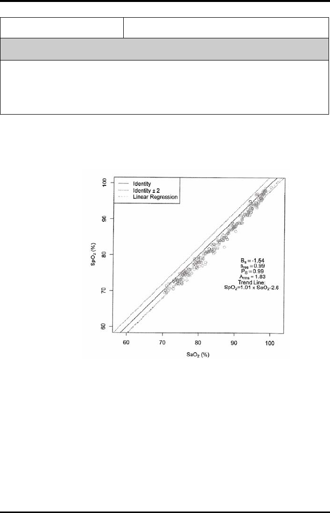
Product Specifications Measurement Specifications
TMS60 Operator’s Manual A - 15
A.8.2.2 Fitting Curve for Nonin SpO2 Sensors
7000A, 7000P, 8000AA, 8000AP
SpO2 = 1.01 × SaO2 – 2.6
Scatter Plot of the SpO2 versus the SaO2
Accuracy ±3 bpm
Response Time
■≤ 25 s (PR 75 bpm, average time 4 heart beats, no disturbance, SpO2 value rises from 70% to
100%)
■≤ 35 s (SpO2 value 98%, average time 4 heart beats, no disturbance, PR value rises from 60
bpm to 150 bpm)
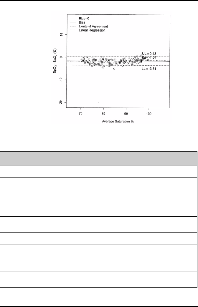
Measurement Specifications Product Specifications
A - 16 TMS60 Operator’s Manual
Bland-Altman Plots of the Bias versus the Mean
A.8.2.3 Masimo SpO2 Module
SpO2
Measurement range 1% to 100%
Resolution 1%
Accuracy
70 to 100%: ±2% (measured without motion in adult/pediatric
mode)
70 to 100%: ±3% (measured with motion)
1% to 69%: Not specified.
Low Perfusion Conditions Pulse amplitude: > 0.02%
Light penetration: > 5%
Low Perfusion Accuracy 2%
*SpO2 accuracy was determined by testing on healthy adult volunteers in the range of 60% to 100% SpO2
against a laboratory CO-Oximeter. SpO2 accuracy was determined on 16 neonatal NICU patients ranging in age
from 7-135 days old and weighing between 0.5-4.25 kg. Seventy-nine (79) data samples were collected over
range of 70-100% SaO2 with a resultant accuracy of 2.9% SpO2.
The following table shows the accuracy (Arms) for the SpO2 sensors in four kinds of SaO2 ranges. For the Fitting
Curve of the SpO2 sensors, refer to the "Fitting Curve for Masimo SpO2 Sensors" on page A - 18.

Product Specifications Measurement Specifications
TMS60 Operator’s Manual A - 17
SaO2 range
Measured Arms Values
LNCS Adtx, LNCS Pdtx LNCS DCI, LNCS DCIP
70% to 100% ± 2% 2%
70% to 80% 1.55% 0.60%
80% to 90% 1.07% 0.54%
90% to 100% 1.64% 0.60%
PR
Measurement range 25 bpm to 240 bpm
Resolution 1 bpm
Accuracy ± 3 bpm (without motion)
± 5 bpm (with motion)
Response Time
≤ 25 s (PR 75 bpm, average time 8 s, no disturbance, SpO2 value rises
from 50% to 100%)
≤ 20 s (SpO2 value 98%, average time 8 s, no disturbance, PR value
rises from 60 bpm to 150 bpm)
PI
Measurement range 0.02% to 20%
Least resolution 0.01, use three valid digits
Response Time
■≤ 25 s (PR 75 bpm, average time 8 s, no disturbance, SpO2 value rises from 50% to 100%)
■≤ 20 s (SpO2 value 98%, average time 8 s, no disturbance, PR value rises from 60 bpm to 150
bpm)
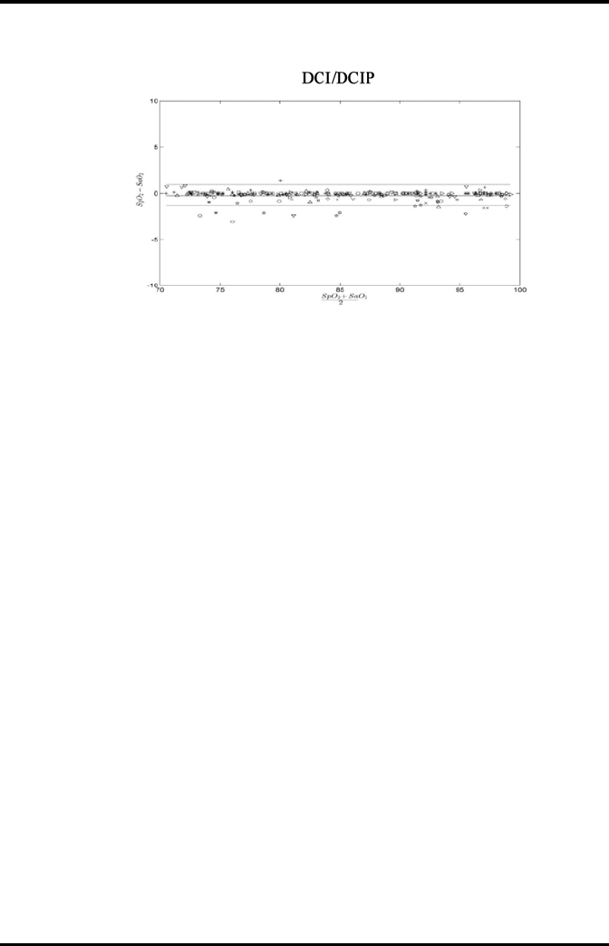
Measurement Specifications Product Specifications
A - 18 TMS60 Operator’s Manual
A.8.2.4 Fitting Curve for Masimo SpO2 Sensors

TMS60 Operator’s Manual B - 1
BEMC

EMC
B - 2 TMS60 Operator’s Manual
The telemetry monitoring system (TMS) meets the requirements of IEC 60601-1-2.
WARNING
•Use of accessories and cables other than those specified may result in
increased emission and/or decreased immunity of the system.
•Devices too close or stacked may interfere with each other. Do not put
devices too close or stack them together. Keep a close eye on the system
in case there are other devices around it.
•Neighboring frequencies of transmitters too close may interfere with
each other, and the CS cannot receive data or receive erroneous data.
Therefore it is recommended that the interval of neighboring
frequencies is not smaller than 25kHz.
•Devices even in compliance with CISPR transmitting requirements may
interfere with the system.
•If the input signal is lower than the specified threshold, measurements
may be inaccurate.
•Other equipment that have RF transmit or source may affect this device
(for example, cell phones, PDAs, PCs with wireless function).
Guidance and declaration — electromagnetic emissions
The system is intended for use in the electromagnetic environment specified below.
The user of the system should assure that it is used in such an environment.
Emissions test Compliance Electromagnetic environment — guidance
RF emissions
CISPR 11
Group 1 The system uses RF energy only for its internal function.
Therefore, its RF emissions are very low and are not likely
to cause any interference in nearby electronic equipment.
RF emissions
CISPR 11
Class A The system is suitable for use in all establishments other
than domestic and those directly connected to the public
low-voltage power supply network that supplies
buildings used for domestic purposes.
Harmonic
Emissions IEC61000-3-2
Class A
Voltage Fluctuations/Flicker
Emissions IEC 61000-3-3
Compliance

EMC
TMS60 Operator’s Manual B - 3
Guidance and declaration — electromagnetic immunity
The system is intended for use in the electromagnetic environment specified below.
The user of the system should assure that it is used in such an environment.
Immunity test IEC 60601 Test
level
Compliance
level Electromagnetic environment - guidance
Electrostatic
Discharge (ESD)
IEC 61000-4-2
± 6 kV contact
± 8 kV air
Floors should be wood, concrete or ceramic
tile. If floors are covered with synthetic
material, the relative humidity should be at
least 30%.
Electrical fast
Transient/burst
IEC 61000-4-4
± 2 kV for power cord
± 1 kV for I/O cables
Mains power quality should be that of a
typical commercial or hospital environment.
Surge IEC
61000-4-5
± 1 kV different mode
± 2 kV common mode
Voltage dips,
Short
interruptions
and voltage
variation on
power supply
input lines IEC
61000-4-11
<5% UT (>95% dip in UT)
for 0.5 cycle
40% UT (60% dip in UT)
for 5 cycle
70% UT (30% dip in UT)
for 25 cycle
<5% UT (>95% dip in UT)
for 5 sec
Mains power quality should be that of a
typical commercial or hospital environment.
If the user of our product requires continued
operation during power mains interruptions,
it is recommended that our product be
powered from an uninterruptable power
supply or a battery.
Power
frequency
(50/60 Hz)
magnetic field
IEC 61000-4-8
3 A/m Power frequency magnetic fields should be
at levels characteristic of a typical location in
a typical commercial or hospital
environment.
Note: UT is the A.C. mains voltage prior to application of the test level.
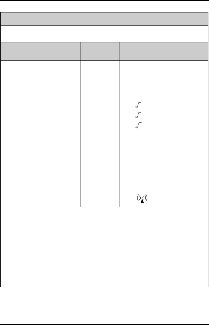
EMC
B - 4 TMS60 Operator’s Manual
Guidance and declaration — electromagnetic immunity
The system is intended for use in the electromagnetic environment specified below.
The customer or the user of the system should assure that it is used in such an environment.
Immunity test IEC 60601 Test
level
Compliance
level Electromagnetic environment - guidance
Conduced RF
IEC 61000-4-6
3 Vrms 150kHz to
80MHz
3 Vrms Portable and mobile RF communications
equipment should be used no closer to any
part of the system, including cables, than the
recommended separation distance
calculated from the equation applicable to
the frequency of the transmitter.
Recommended separation distance
d = 1.2
d = 1.2 80 M to 800 MHz
d = 2.3 800 M to 2.5 GHz
where P is the maximum output power
rating of the transmitter in watts (W)
according to the transmitter manufacturer
and d is the recommended separation
distance in meters (m).
Field strengths from fixed RF transmitters, as
determined by an electromagnetic site
survey a, should be less than the compliance
level in each frequency range b.
Interference may occur in the vicinity of
equipment marked with the following
symbol:
Radiated RF IEC
61000-4-3
3 V/m 80MHz to
2.5GHz
3 V/m
Note: At 80 MHz and 800 MHz, the higher frequency range applies.
Note: These guidelines may not apply in all situations. Electromagnetic propagation is affected by absorption
and reflection from structures, objects and people.
Note: The TMS that intentionally receives RF electromagnetic energy at the exclusion band (2395.825MHz-
2487.645MHz) is exempt from the ESSENTIAL PERFORMANCE requirements, but remains safe.
a: Field strengths from fixed transmitters, such as base stations for radio (cellular/cordless) telephones and land
mobile radios, amateur radio, AM and FM radio broadcast and TV broadcast cannot be predicted theoretically
with accuracy. To assess the electromagnetic environment due to fixed RF transmitters, an electromagnetic site
survey should be considered. If the measured field strength in the location in which the system is used exceeds
the applicable RF compliance level above, the system should be observed to verify normal operation. If
abnormal performance is observed, additional measures may be necessary, such as reorienting or relocating
the system.
b: Over the frequency ranges 150kHz to 80MHz, field strengths should be less than 3V/m.
P
P
P
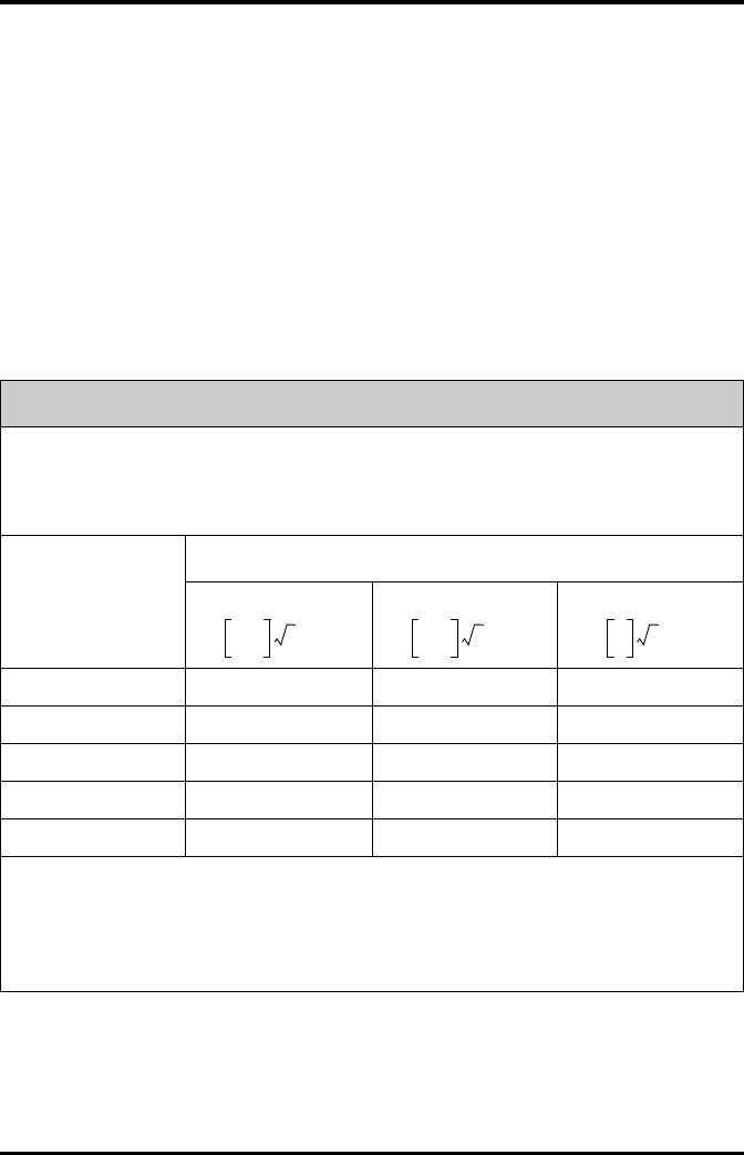
EMC
TMS60 Operator’s Manual B - 5
If the system is operated within the electromagnetic environment listed in Table Guid-
ance and declaration — electromagnetic immunity, the system will remain safe and
provide the following essential performance:
■Operating mode
■Accuracy
■Function
■Accessories identification
■Data stored
■Alarm
■Detect for connection
Recommended separation distances between portable and mobile RF communication and the system
The system is intended for use in an electromagnetic environment in which radiated RF disturbance are
controlled. The customer or the user of the system can help prevent electromagnetic interference by
maintaining a minimum distance between portable and mobile RF communication equipment (transmitters)
and the system as recommended below, according to the maximum output power of the communication
equipment.
Rated Maximum
Output power of
Transmitter W (Watts)
Separation Distance According to Frequency of Transmitter M (Meters)
150kHz -80MHz
d =
80MHz to 800MHz
d =
800MHz to 2.5GHz
d =
0.01 0.12 0.12 0.23
0.1 0.37 0.37 0.74
1 1.17 1.17 2.34
10 3.69 3.69 7.38
100 11.67 11.67 23.34
For transmitters at a maximum output power not listed above, the recommended separation distanced in
meters (m) can be determined using the equation applicable to the frequency of the transmitter, where P is the
maximum output power rating of the transmitter in watts (W) according to the transmitter manufacturer.
Note: At 80 MHz and 800 MHz, the separation distance for the higher frequency range applies.
Note: These guidelines may not apply in all situations. Electromagnetic propagation is affected by absorption
and reflection from structures, objects and people.
3.5
3
---------
P
3.5
3
---------
P
7
3
---
P

EMC
B - 6 TMS60 Operator’s Manual
This page intentionally left blank.

TMS60 Operator’s Manual C - 1
CFCC Compliance
The telemetry monitoring system (TMS) complies with the requirements of FCC Part 95:
Authorized health care providers, in conjunction with the equipment manufacturers,
must cooperate in the selection and use of frequencies in order to reduce the potential
for interference with other wireless medical telemetry devices, or other co-primary users.
Operations in the 608–614 MHz band (television channel 37) are not protected from
adjacent band interference from broadcast television operating on channels 36 and 38.
As the RF range of the system is 608-614Mhz, if located near the radio astronomy obser-
vatories the two parties will interfere with each other.
Therefore, we don't suggest that the equipment can be installed or operated within 80
kilometers of:
1. National Astronomy and Ionosphere Center, Arecibo, Puerto Rico: 18°20′38.28″
North Latitude, 66°45′09.42″ West Longitude.
2. National Radio Astronomy Observatory, Socorro, New Mexico: 34°04′43″ North Lat-
itude, 107°37′04″ West Longitude.
3. National Radio Astronomy Observatory, Green Bank, West Virginia: 38°26′08″
North Latitude, 79°49′42″ West Longitude.
This device and its antenna must not be located or operating in conjunction with any
other antenna and transmitter.
This device complies with part 15 of the FCC rules. Operation is subject to the following
two conditions: (1) this device may not cause harmful interference, and (2) this device
must accept any interference received, including interference that may cause undesired
operation.
Changes or modifications not expressly approved by the party responsible for compli-
ance could void the user’s authority to operate the equipment.

FCCCompliance
TMS60Operator’sManualC‐3
NOTE
● ThisequipmenthasbeentestedandfoundtocomplywiththelimitsforaClassBdigitaldevice,
pursuanttopart15oftheFCCRules.Theselimitsaredesignedtoprovidereasonable
protectionagainstharmfulinterferenceinaresidentialinstallation.Thisequipmentgenerates
usesandcanradiateradiofrequencyenergyand,ifnotinstalledandusedinaccordancewiththe
instructions,maycauseharmfulinterferencetoradiocommunications.However,thereisno
guaranteethatinterferencewillnotoccurinaparticularinstallation.Ifthisequipmentdoes
causeharmfulinterferencetoradioortelevisionreception,whichcanbedeterminedbyturning
theequipmentoffandon,theuserisencouragedtotrytocorrecttheinterferencebyoneor
moreofthefollowingmeasures:
Reorientorrelocatethereceivingantenna.
Increasetheseparationbetweentheequipmentandreceiver.
Connecttheequipmentintoanoutletonacircuitdifferentfromthattowhichthereceiver
isconnected.
RadioFrequencyExposure
ThisequipmentcomplieswithFCCradiationexposurelimitssetforthforanuncontrolled
environment.
Thistransmittermustnotbeco‐locatedoroperatinginconjunctionwithanyotherantennaor
transmitter.
Operationofthisequipmentrequiresthepriorcoordinationwithafrequencycoordinator
designatedbytheFCCfortheWirelessMedicalTe le metry Service.
RadiofrequencyRadiationExposureInformation
Forbodywornoperation,thisequipmenthasbeentestedandmeetstheFCCandCERFexposure
guidelineswhenusedwiththeaccessoriessuppliedorthoseapprovedforusewiththisproduct.
UseofotheraccessoriesmaynotensurecompliancewithFCCandCERFexposureguidelines
within32kilometersoftheNationalRadioAstronomyObservatorycenteredon:

FCCCompliance
TMS60Operator’sManualC‐3
VerylongbaselinearraystationsLatitude(north)Longitude(west)
PieTown,NM34°18′108°07′
KittPeak,AZ31°57′111°37′
LosAlamos,NM35°47′106°15′
FortDavis,TX30°38′103°57′
NorthLiberty,IA41°46′91°34′
Brewster,WA48°08′119°41′
OwensValley,CA37°14′118°17′
SaintCroix,VI17°46′64°35′
MaunaKea,HI19°49′155°28′
Hancock,NH42°56′71°59′
Iftheinstallationdistanceisnotenough,obtainthewrittenconcurrenceoftheDirectorofthe
affectedradioastronomystationbeforetheequipmentcanbeinstalledoroperated.
RFParameters

FCC Compliance
C - 4 TMS60 Operator’s Manual
Item Parameter
Operating Frequency Band (MHz) 608 to 614
Modulation GFSK
Transmitter Output Power(e.i.r.p) (dBm) < 10
Channel Space (KHz) 25

TMS60 Operator’s Manual D - 1
DSymbols and Abbreviations
Units..............................................................................................................................D-2
Symbols.......................................................................................................................D-3
Abbreviations............................................................................................................D-3

Units Symbols and Abbreviations
D - 2 TMS60 Operator’s Manual
D.1 Units
Aampere
Ah ampere hour
bpm beats per minute
°C centigrade
cc cubic centimeter
cm centimeter
dB decibel
DS dyne. second
°F fahrenheit
ggram
hr hour
hPa hundred pascal
Hz hertz
in inch
kkilo
kg kilogram
kPa kilopascal
llitre
lb pound
mmeter
mg milligrams
min minute
ml milliliter
mm millimeters
ms millisecond
mV millivolt
mW milliwatt
nm nanometer
ppm part per million
ssecond
Vvolt
VA volt ampere
ohm
A microampere
m micron

Symbols and Abbreviations Symbols
TMS60 Operator’s Manual D - 3
D.2 Symbols
D.3 Abbreviations
V microvolt
Wwatt
-minus
%percent
/ per; divide; or
^power
+plus
=equal to
<less than
> greater than
≤ less than or equal to
≥ greater than or equal to
±plus or minus
× multiply
©copyright
AAMI Association for Advancement of Medical Instrumentation
AC alternating current
AHA American Heart Association
ANSI American National Standard Institute
ARR arrhythmia
ART arterial
AUX Auxiliary output
aVF left foot augmented lead
aVL left arm augmented lead
aVR right arm augmented lead
CH channel
CISPR International Special Committee on Radio Interference
CS central station
ECG electrocardiograph
EMC electromagnetic compatibility

Abbreviations Symbols and Abbreviations
D - 4 TMS60 Operator’s Manual
err error
ES electrosurgical
ESU electrosurgical unit
HR heart rate
HT height
IEC International Electrotechnical Commission
ISO International organization for standardization
MRI magnetic resonance imaging
LA(L) left arm
LAP left atria pressure
LED light emitting diode
LL(F) left leg
Loop loop read-write test fail
M, MEAN mean pressure
O2 oxygen
Ppower
PAN Patient Area Network
PR pulse rate
QRS interval of ventricular depolarization
(QRS complex)
RA(R) right arm
RL(N) right leg
ROM read-only memory
SpO2arterial oxygen saturation from pulse oximetry
VGA Video Graphics Array

TMS60 Operator’s Manual E - 1
EAnomaly
E.1 Anomaly Description
This product does not have any anomalies.

Anomaly Description Anomaly
E - 2 TMS60 Operator’s Manual
This page intentionally left blank.
P/N: 046-007056-00 (1.0)