Mipro Electronics Co ACT8H Transmitter User Manual ACT8H ACT8T 2CE263
Mipro Electronics Co Ltd Transmitter ACT8H ACT8T 2CE263
Contents
- 1. Manual part 1
- 2. Manual part 2
- 3. Manual part 3
- 4. Manual part 4
Manual part 3
16
5
15
FREQ
MODE
SET OFF
SET ON
RF RF
AF AF
BT BT
RF
AF BT
5
LOW--CU
MODE ON
OFF
SET
**NOTE: When program a special frequency via monitoring software;
LCD screen cannot display the number. This is because this special
channel is not in the preset group and channel. Therefore, LCD panel
will look like illustration below.
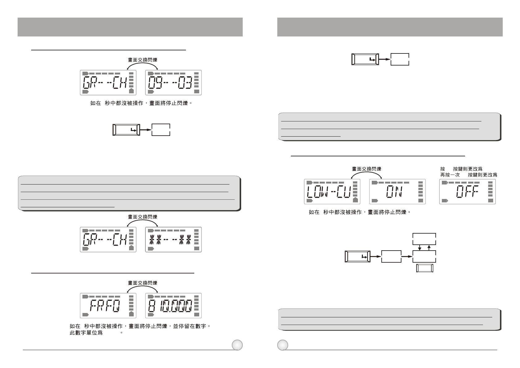
(1)GR-CH: Displays Information of Group and Channel
RF
RF
AF
AF
BT
BT
RF
RF
AF
AF
BT
BT
5
B. Operation Guide:
a. Press ''MODE'' and stop on "GR-CH" function, the display showing current group
and channel will be flashing. After 5 seconds, the display will stop flashing.
b. "GR-CH" function is added to display group and channel information. Changing
current group and channel must be done on the receiver.
GR--CH
MODE
RF
AF BT
RF
AF BT
5
"MHz"
A. Operate via MODE Button
(2) FREQ: Displays Information of Transmitter Frequency
A. Operate via MODE Button
B. Operation Guide:
a. Press ''MODE'' and stop on "FREQ" function, the display showing current
frequency will be flashing. After 5 seconds, the display will stop flashing.
B. "FREQ" function is added to display frequency information. Changing current
frequency must be done on the receiver.
**NOTE: To modify transmitter's group, channel and frequency, all
three must be set at the receiver and transmit the new setting to
transmitter via ACT.
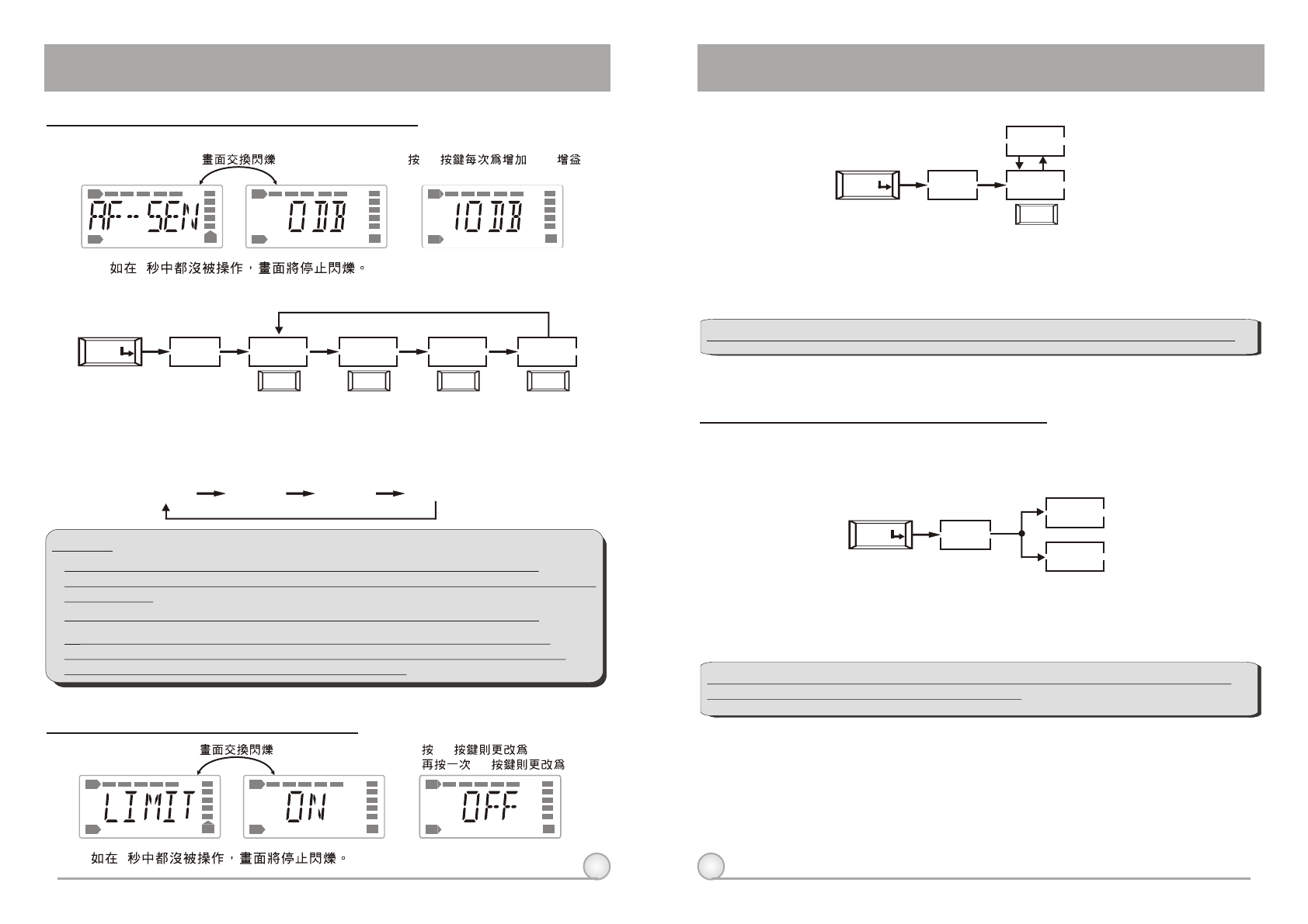
(3) LOW-CU: Setup and Change of Low Frequency Cut Off
B. Operation Guide:
A. Operate via MODE Button
a. Press ''MODE'' and stop on "LOW-CU" function, the display showing current state
will be flashing and is ready to be modified.
b. Press ''SET'' button to change to ''ON'' or ''OFF'' as desired.
**NOTE: When the LOW-CU function is ''ON'', the frequency response
below 100Hz will decrease about 4dB with a slope of -6dB/Octave.
DIGITAL WIRELESS BODY PACK TRANSMITTER DIGITAL WIRELESS BODY PACK TRANSMITTER
17
18
SET OFF
SET ON
RF RF
AF AF
BT BT
RF
AF BT
5
LIMIT
MODE ON
OFF
SET
SET 10dB
RF RF
AF AF
BT BT
RF
AF BT
5
AF--SEN
MODE 0 DB
SET
10 DB
SET
20 DB
SET
30 DB
SET
0 DB 10 DB 20 DB 30 DB
ENCRYP
MODE
ON
OFF
DIGITAL WIRELESS BODY PACK TRANSMITTER DIGITAL WIRELESS BODY PACK TRANSMITTER
(4) AF-SEN: Setup and Change of Input Sensitivity
A. Operate via MODE Button
B. Operation Guide:
a. Press "MODE" and stop on "AF-SEN" function, the display showing current state
will be flashing and is ready to be modified.
b. Every push of ''SET'' button, the dB value increases by 10dB to a maximum of
30dB.
**NOTE:
1. The higher the gains are set, the lower the dynamic range for signal input.
Meanwhile the danger of unwanted noises and feedback getting into the system would
obviously rise.
2. It is advisable to set the sensitivity level at 0dB when using electric guitar.
3. When set at 0 dB, the maximum input level without causing distortion to the
transmitter is 1 Vrms (0 dBv). Hence, please make sure the input signal does not
exceed 1 Vrms. SPL for handheld microphone is 145dB.
(5) LIMIT: Setup and Change of Input Limit
A. Operate via MODE Button
B. Operation Guide:
a. Press "MODE" and stop on "LIMIT" function, the display showing current state will
be flashing and is ready to be modified.
b. Press ''SET'' to change the setting to "ON" or "OFF".
**NOTE: When the LIMIT is ''ON'', the maximum output of the receiver is limited to 1V.
(6) ENCRYP: Displays Information of Encryption
A. Operate via MODE Button
B. Operation Guide:
a. Press "MODE" and stop on "ENCRYP" function, the display showing current state
will be flashing.
**NOTE: "ENCRYP" function is added to display status information only. Changing of
current status must be done from receiver via ACT.
19
20
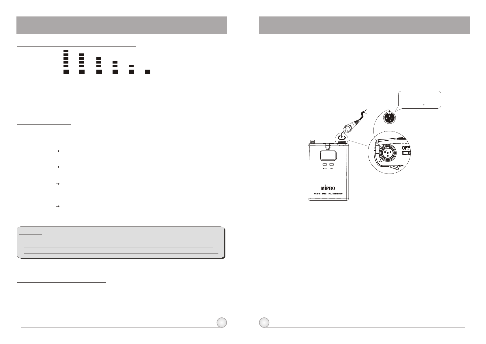
4. Cautions
1. Adjust the gain knob to the appropriate level (The gain level needs to be set
at 0dB level when using an electric guitar).
2. Plug the microphone connector into the AF input (1) and then secure the
connector by turning it in a clockwise direction, as shown in Fig. 4.
3. When the antenna has been removed, the body pack transmitter should
remain ''OFF'' to prevention future deterioration of signal transmission.
4. If the transmitter is on without any microphone connected to the AF input
socket, the system will clearly have noises of both high and low frequencies.
They will do no harm to the system, but will be annoying to the listener, so it
would be best to switch off the transmitter when disconnecting the
microphone.
BT BT BT BT BT
90% 80% 40% 10% 0%
BT
100%
DIGITAL WIRELESS BODY PACK TRANSMITTER DIGITAL WIRELESS BODY PACK TRANSMITTER
7. BT: Displays Information of Battery Level
When the battery level drops down to 10%, please replace or recharge the
battery. If the battery continues to be used at a very lower level, the LCD will
display and then automatically switch off to avoid over-discharging the
battery.
"PO--OFF"
8. ERR: Error Code
ROM-ER Transmitter does not have the initial data so the
microphone is completely dead.
ERROR1 Failure on RF circuitry, frequency can not be
programmed.
NO----O3 Frequency to be programmed into the transmitter
exceeds its highest frequency of designated frequency
band of the transmitter.
NO----O4 Frequency to be programmed into the transmitter
exceeds its lowest frequency of designated frequency
band of the transmitter.
(9) PO-OFF: System Turning Off
When the power is turned off, the LCD displays ''PO-OFF''
indicating the system is at the state of shutting down and then
automatically cuts the power off. The display panel has no further
message afterward.
If the LCD displays ''ERR'' after turning on the power, it indicates the
operation is not correct. The error codes are as follows:
**NOTE:
NO----OR3 and NO----OR4 will not change transmitter's original frequency, and the
transmitter still operates normally with error message on display.. To remove error
message from display panel, please switch off the transmitter and switch it on again.
Lavalier
Headset
Capsule Connector
The ridge on the
connector must match the
indentation on the socket
when inserting.
(Fig.4)
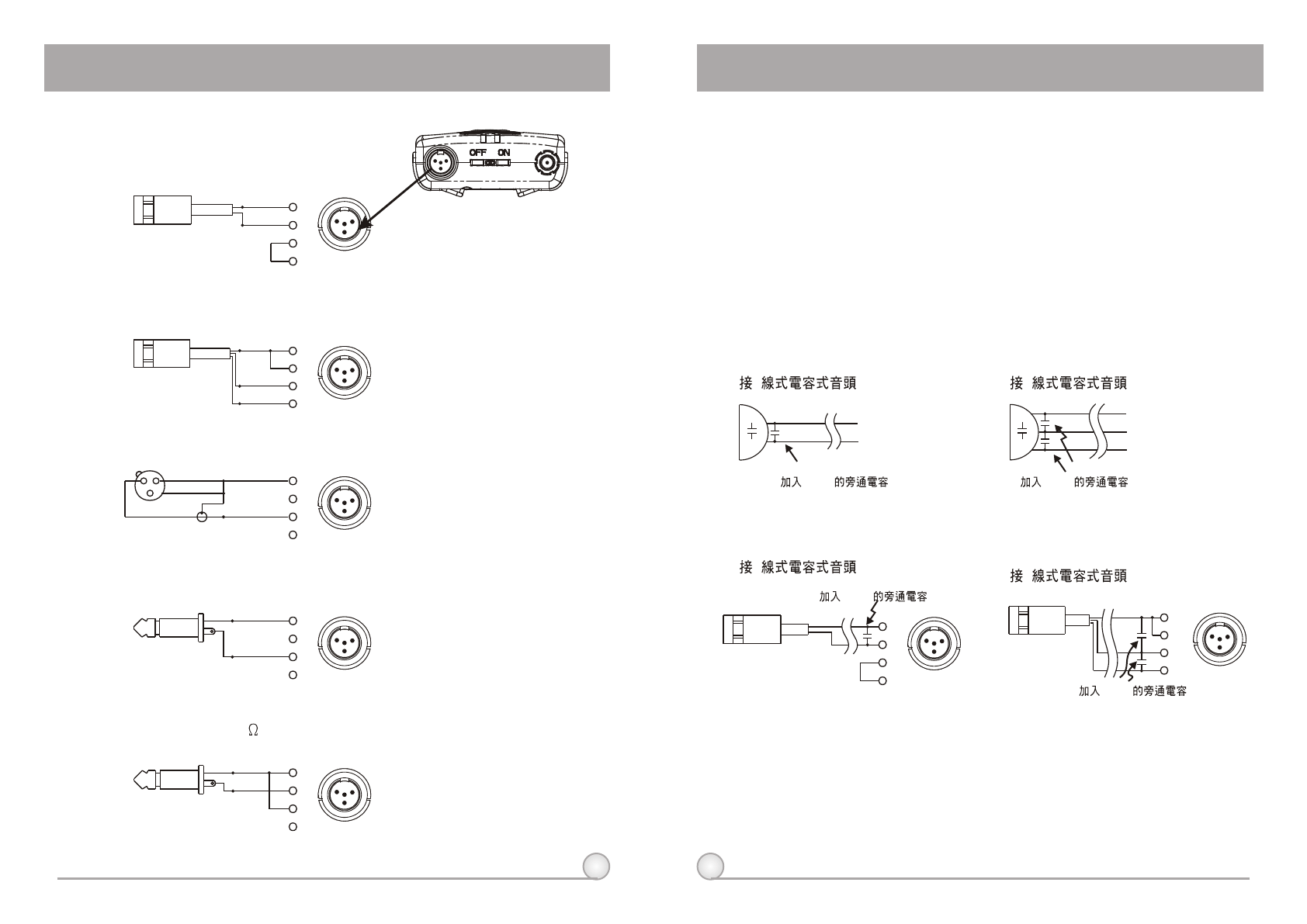
6. High Frequency Bypass
a. When other microphones are in use, some changes may be needed to
another microphone before adding it to the system in order to avoid high
frequency interference, as illustrated in diagram (1).
b. When a high frequency radio wave causes interference, it normally affects
the system by generating a persistent noise or by deteriorating the frequency
response. In an effort to ameliorate these problems, a 330PF bypass
condenser can be added on the cartridge as shown in diagrams (1) and (2).
If this method is not possible, another option is to add a bypass condenser
on the 4-pin XLR connector as shown in diagrams (3) and (4).
(1) 2
330PF
(2) 3
**The Best Method
**Alternate Method
1
3
4
2
PIN
13
4
23
4
PIN
1
213
4
2
(3) 2 (4) 3
330PF
330PF
330PF
21
22
5. AF Input Connection Methods
AUDIO
SHIELD PIN
4
3
2
1
SHIELD
AUDIO
BIAS
PIN
3
4
1
2
AUDIO
SHIELD 1
4
3
2
PIN
SHIELD
AUDIO
3
2 1 PIN
4
3
2
1
SHIELD
AUDIO
1
3
4
2
PIN
13
4
2
13
4
2
13
4
2
13
4
2
13
4
2
DIGITAL WIRELESS BODY PACK TRANSMITTER DIGITAL WIRELESS BODY PACK TRANSMITTER
(1) 2-Wire Electret Condenser Microphone Capsule
(2) 3-Wire Electret Condenser Microphone Capsule
(3) Dynamic Microphone
(4) Electric Guitar
(5) Line-in (Impedance 8K ATT. 10dB)