Mipro Electronics Co MI909T Wireless Digital Stereo Transmitter User Manual MI 909T 2CE497B x3 201410
Mipro Electronics Co Ltd Wireless Digital Stereo Transmitter MI 909T 2CE497B x3 201410
UserManual.wiki
>
Mipro Electronics Co
>
MI909T User Manual
Users Manual
Navigation menu
Upload a User Manual
Namespaces
Wiki Guide
HTML
PDF
Info
Views
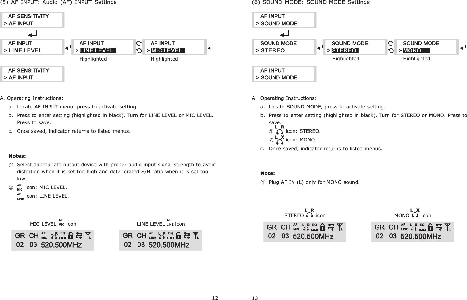
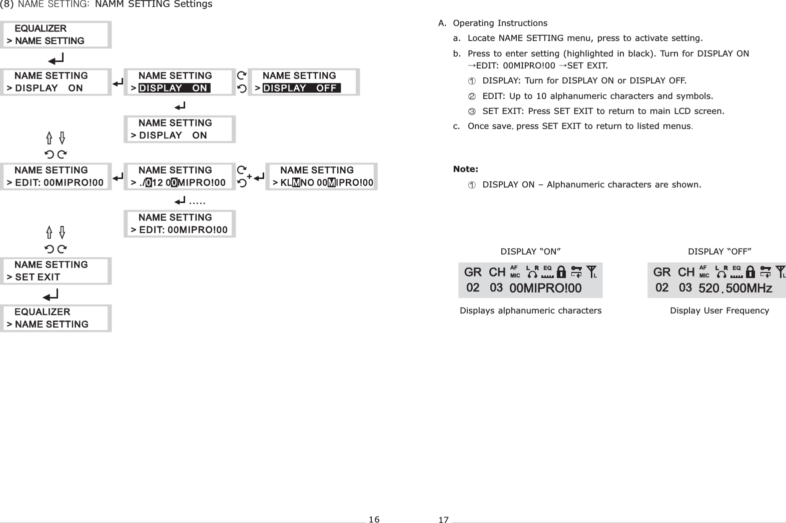
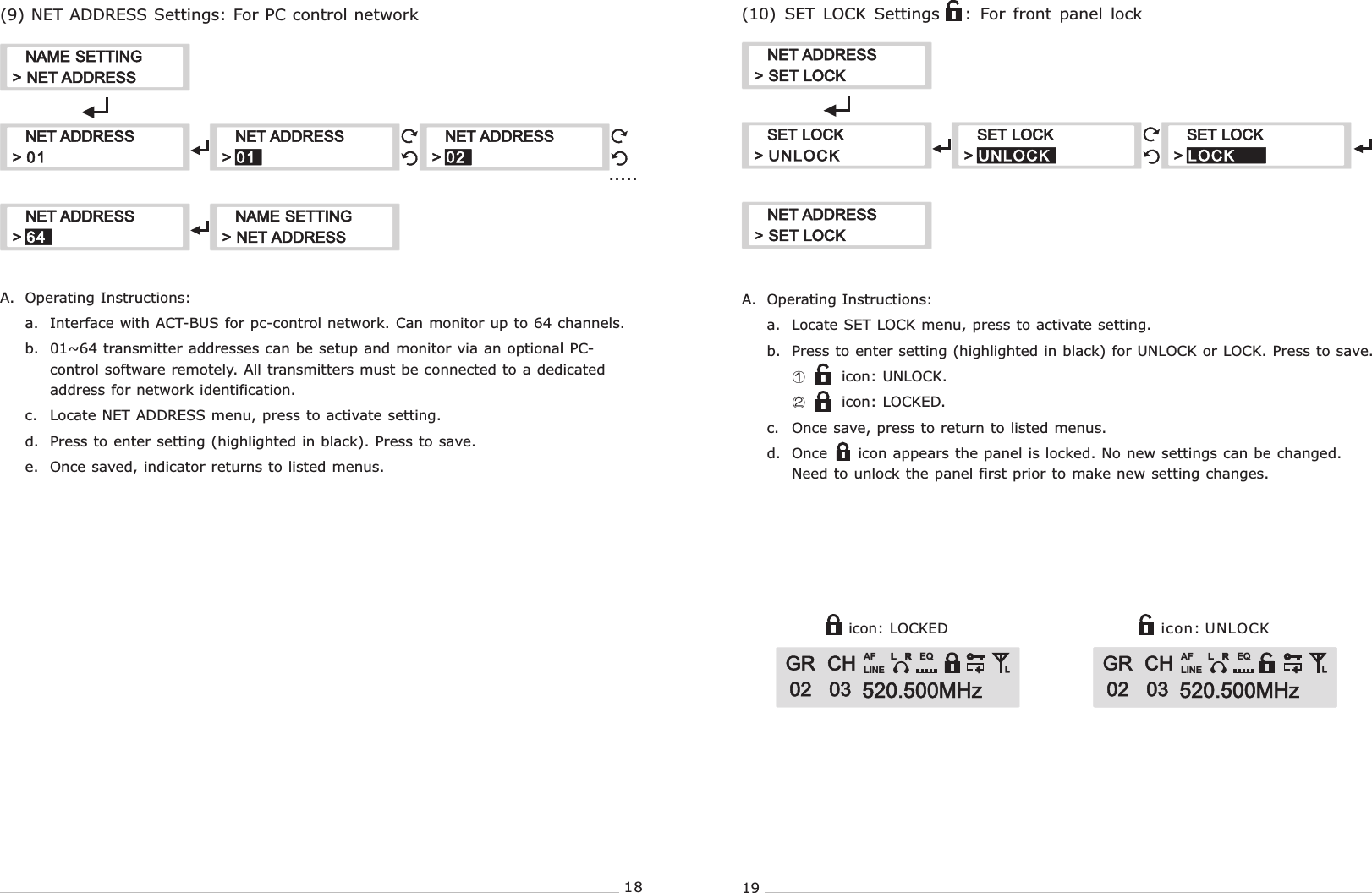
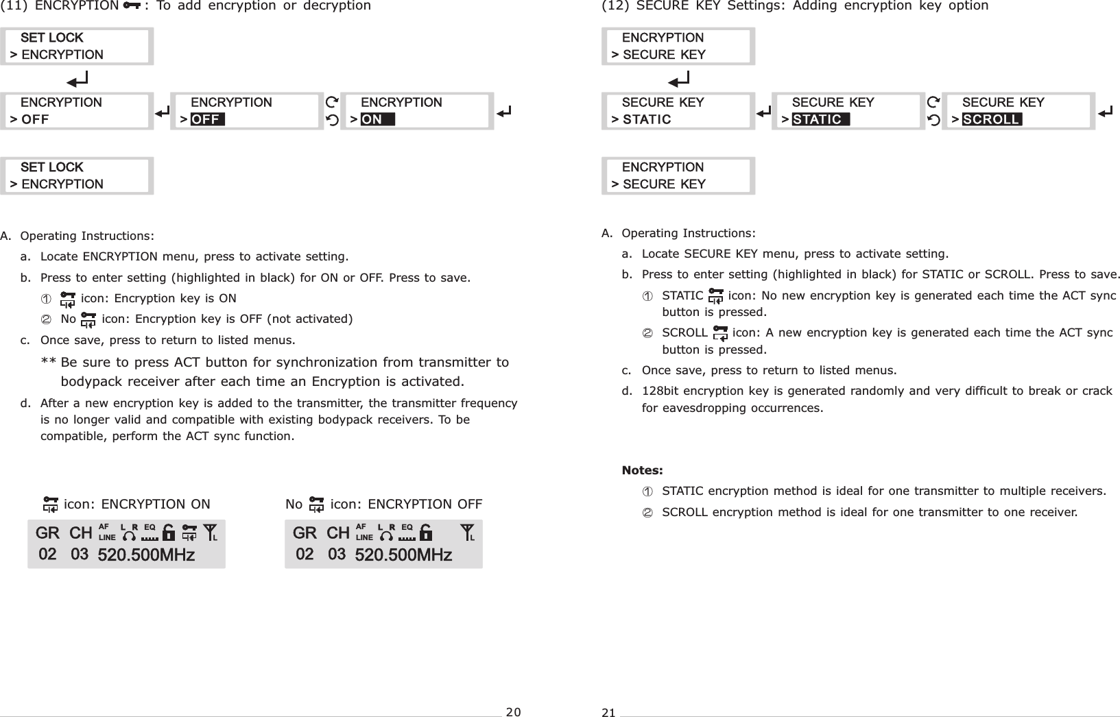
User Manual
Discussion / Help
Navigation