Mipro Electronics Co MI909T Wireless Digital Stereo Transmitter User Manual MI 909T 2CE497B x3 201410
Mipro Electronics Co Ltd Wireless Digital Stereo Transmitter MI 909T 2CE497B x3 201410
Users Manual
1. Read these instructions.
2. Keep these instructions.
3. Heed all warnings.
4. Follow all instructions.
5. Do not use this apparatus near water.
6. Clean only with a dry cloth.
7. Do not block any ventilation openings. Install in accordance with the manufacturer's
instructions.
8. Do not install near any heat sources such as radiators, heat registers, stoves, or
other apparatus (including amplifiers) that produce heat.
9. Do not defeat the safety purpose of the polarised or ground plug: A polarised plug
has two blades with one wider than the other. The wide blade is provided for your
safety. When the provided plug does not fit into your outlet, consult an electrician
for replacement of the obsolete outlet.
10. Protect the power cord from being walked on or pinched particularly at plug,
convenience receptacles, and the point where they exit from the apparatus.
11. Only use attachments/accessories specified by the manufacturer.
12. Use only with a cart, stand, tripod, bracket, or table specified by the
manufacturer, or sold with the apparatus. When a cart is used, use
caution when moving the cart/apparatus combination to avoid injury
from tip-over.
13. Unplug this apparatus during lightning storms or when unused for long periods of
time.
14. Refer all servicing to qualified service personnel. Servicing is required
when the apparatus has been damaged in any way, such as power-supply
cord or plug is damaged, liquid has been spilled or objects have fallen into
the apparatus, the apparatus has been exposed to rain or moisture, does not
operate normally, or has been dropped.
15. To reduce the risk of fire or electric shock, do not expose this apparatus to rain or
moisture.
16. Apparatus should not be exposed to dripping or splashing and no objects filled with
liquids, should be placed on the apparatus.
17. Use only with the battery which specified by manufacturer.
18. The power supply cord set is to be the main disconnected device.
! IMPORTANT SAFETY INSTRUCTIONS ! WARNING
This symbol indicates that dangerous voltage constituting a risk of electric
shock is present within this unit.
This symbol indicates that there are important operating and maintenance
instructions in the literature accompanying this unit.
1. FOR OUTDOOR USE:
To reduce the risk of fire or electric shock, do not expose this apparatus to rain or
moisture.
2. UNDER WET LOCATION:
Apparatus should not be exposed to dripping or splashing and no objects filled with
liquids, such as vases should be placed on the apparatus.
3. SERVICE INSTRUCTIONS:
CAUTION - These servicing instructions are for use by qualified service personnel
only. To reduce the risk of electric shock, do not perform any servicing other than
that contained in the operating instructions unless you are qualified to do so.
FCC
THIS DEVICE COMPLIES WITH PART 74 AND PART 15 SUBPART B OF THE FCC RULES
OPERATION IS SUBJECT TO THE FOLLOWING TWO CONDITIONS:
(1) This device may not cause interference.
(2) This device must accept any interference, including interference that may cause
undesired operation of the device.
This equipment complies with FCC RF radiation exposure limits set forth for an
uncontrolled environment.
IC
This device complies with Industry Canada licence-exempt RSS-123 ISSUE 2 / RSS-310
ISSUE 3 standards. Operation is subject to the following two conditions:
(1) this device may not cause interference, and
(2) this device must accept any interference, including interference that may cause
undesired operation of the device.
Le présent appareil est conforme aux CNR d'Industrie Canada applicables aux appareils
radio exempts de licence. L'exploitation est autorisée aux deux conditions suivantes :
(1) l'appareil ne doit pas produire de brouillage, et
(2) l'utilisateur de l'appareil doit accepter tout brouillage
radioélectrique subi, même si le brouillage est susceptible d'en compromettre le
fonctionnement.

1 Profile
2 Front Panel Controls and Indicators
Rear Panel Connectors
Operating Instructions
LCD Panel Operating Instructions
27
28
3
4
6
25 MIPRO's Proprietary ACT Sync Function
Network Connection
Rackmount Kit
29 Cautions & Recommendations
Profile
Thank you for choosing a MIPRO IEM product.
This industry's first digital IEM system is engineered to meet the stringent
requirements demanded in professional touring and installation applications.
Featuring digitally encrypted technology and unparalleled digital audio
performance and transmission reliability, superior frequency response
characteristics from 20Hz low-frequency sound clearly exceeds analog IEM
systems currently on the market.
Digital Stereo Rack Transmitter
1
Contents
Digital Stereo Rack Transmitter
0
Disposal
2005-08-13
Dispose of any unusable devices or batteries responsibly and in accordance
with any applicable regulations.
Disposing of used batteries with domestic waste is to be avoided!
Batteries / NiCad cells often contain heavy metals such as cadmium(Cd),
mercury(Hg) and lead(Pb) that makes them unsuitable for disposal with
domestic waste. You may return spent batteries/ accumulators free of
charge to recycling centres or anywhere else batteries/accumulators are
sold.
By doing so, you contribute to the conservation of our environment!
To prevent possible hearing damage, do not listen at high volume
levels for long periods.
φ
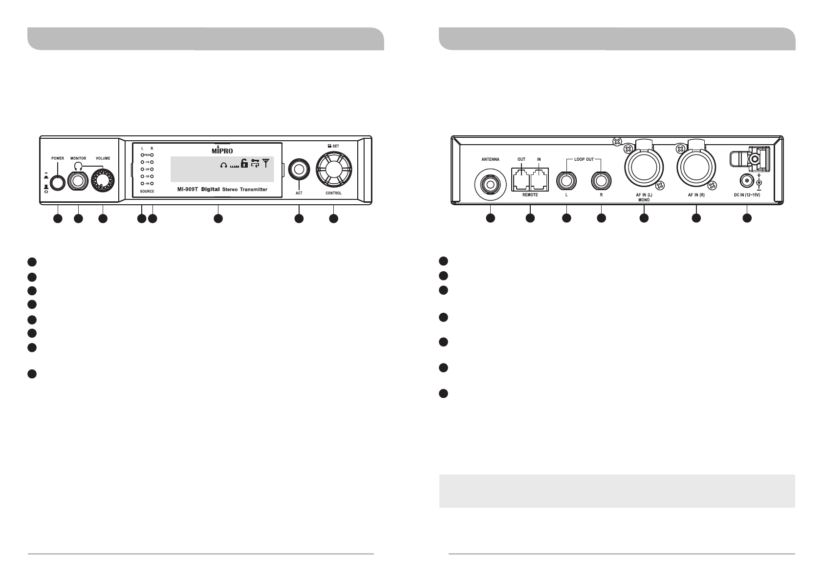
Power Button: Press to turns the unit on and off.
Headphone Monitoring: Insert a 6.3 mm headphone here.
Headphone Volume: Adjust for volume loudness.
Left Audio Indicators: The red Peak LED indicates the inputs are overdriven.
Right Audio Indicators: The red Peak LED indicates the inputs are overdriven.
Front Panel Screen: Display settings and parameters.
ACT Sync Button & Window: Press ACT button to sync frequency from
transmitter to bodypack receivers.
Control Knob: For setting changes.
Rack Transmitter
Front Panel Controls and Indicators
2 3 4 5 8
1
2
3
4
5
6
7
8
7
16
520.500MHz
AF
LINE
02 03
GR CH L R EQ
L
23
Rack Transmitter
Rear Panel Connectors
10 11 12 13 15
914
Antenna Connector (TNC): Attach supplied antenna.
ACT Bus: Attach supplied ACT Bus cable for remote control option.
LOOP OUT Left: Sends a copy of the audio signal going into the transmitter to
another device.
LOOP OUT Right: Sends a copy of the audio signal going into the transmitter to
another device.
Audio Inputs Left (Mono): Connect to balanced or unbalanced outputs. Accepts
both 1/4-inch or male XLR connectors.
Audio Inputs Right: Connect to balanced or unbalanced outputs. Accepts both
1/4-inch or male XLR connectors.
12~15V DC Power: Connect the transmitter to a power outlet using the supplied
power plug & cable.
9
10
11
12
13
14
15
The MI-909 system consists one MI-909T digital rack unit stereo transmitter and will
transmit to one or more MI-909R digital stereo bodypack receivers.
Digital Stereo Rack TransmitterDigital Stereo Rack Transmitter
Operating Instructions
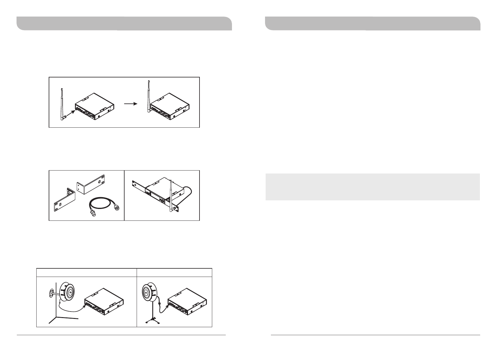
1. Rear Antenna Installation
Attach supplied antenna to the transmitter. Ensure the antenna and transmitter have
the same frequency band for optimal transmitting efficiency
3. External Antenna Installation
Install optional MIPRO AT-100 & MS-90 antennas with microphone stands and high
quality coaxial cable for improved performance. Ensure antennas are installed and
positioned higher than the crowds and away from obstructions.
2. Front Antenna Installation
Install an option FB-71 rear-to-front rackmount kit with cable. Attach supplied
antenna to the front for improved optimal transmitting efficiency.
Wall-mounted AT-100 + MS-90 Mic stand AT-100 + MS-90
45
4.
5.
6.
7.
φ
Power
Connect the transmitter to a power outlet using the supplied power plug & cable.
Power Button
Press to turns the unit on and off.
Audio Inputs
Stereo or Mono outputs. Left audio input for Mono. Accepts both 1/4-inch or male
XLR connectors.
Headphone Monitoring
Insert a 6.3 mm headphone here.
WARNING:
To prevent possible hearing damage, do not listen at high volume levels for long
periods.
Digital Stereo Rack TransmitterDigital Stereo Rack Transmitter
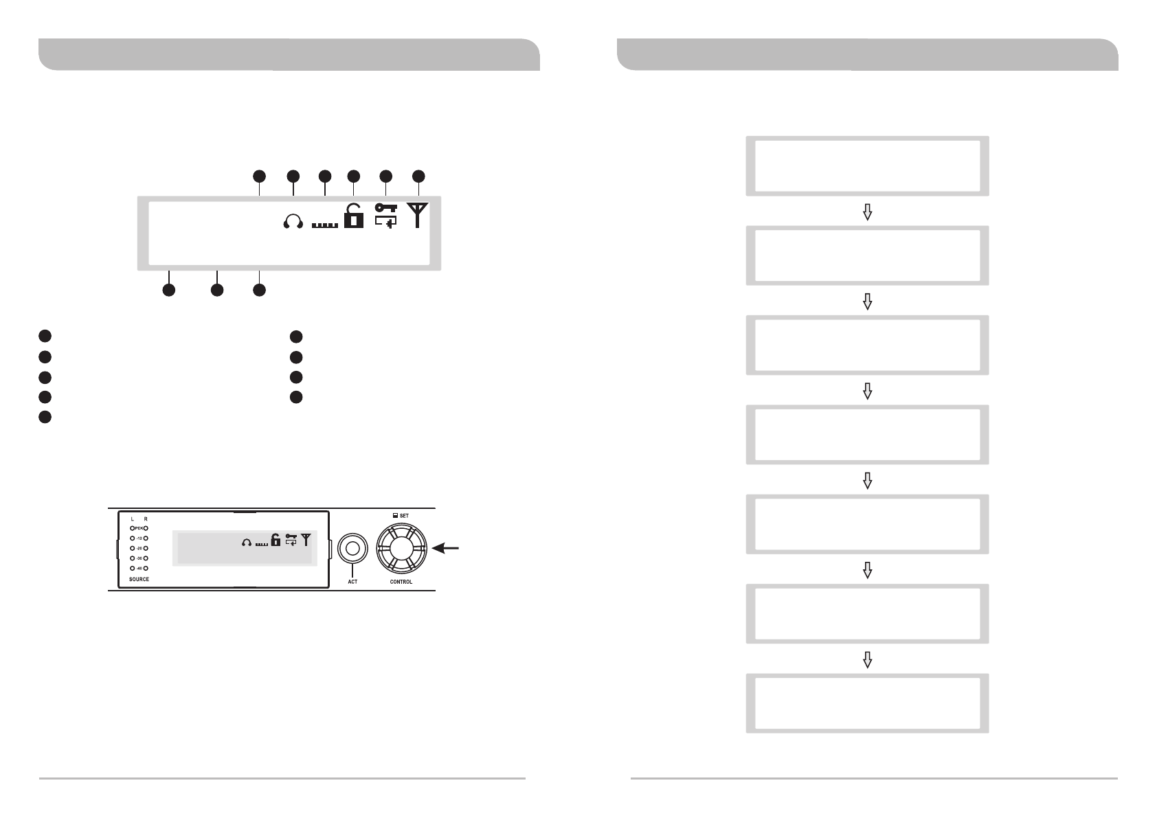
LCD Panel Operating Instructions
520.500MHz
AF
LINE
02 03
GR CH L R EQ
L
A1 A3A2
A5 A6 A7 A8 A9A4
GR: Group
CH: Channel
Working Frequency in MHZ
AF: Audio Frequency
Left Right Channel
A1
A2
A3
A4
A5
EQ icon: Equalizer
Lock Icon
Encryption key Icon
RF output Icon
A6
A7
A8
A9
1. Main LCD Screen provides access to menus and displays a summary of
transmitter settings
2
A. Operating Instructions:
a. Press & release Control Knob to access menus.
b. Turn right or left to access specific menus. Press to confirm setting changes.
. Control Knob: Menu Settings
Control Knob
520.500MHz
AF
LINE
02 03
GR CH L R EQ
L
67
3. Listed Menus
USER FREQUENCY
AF SENSITIVITY
SOUND MODE
NAME SETTING
SET LOCK
SECURE KEY
EXIT & SAVE
> GROUP & CHANNEL
> RF POWER
> AF INPUT
> EQUALIZER
> NET ADDRESS
> ENCRYPTION
> FREE SCAN
Digital Stereo Rack TransmitterDigital Stereo Rack Transmitter
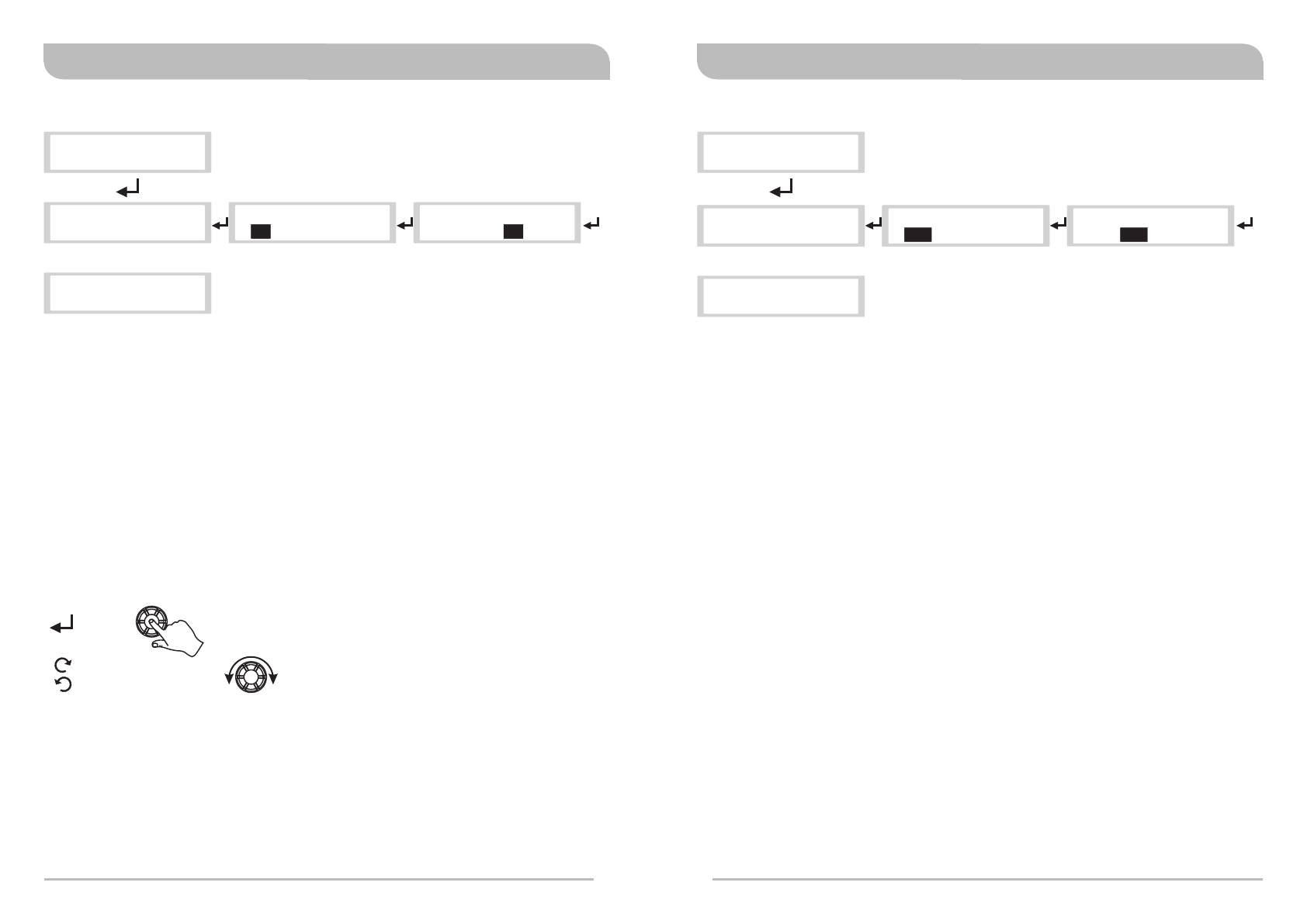
(1) GR CH: GROUP & CHANNEL Settings
89
A.
a.
b.
c.
d.
Operating Instructions:
Locate GROUP & CHANNEL menu, press to activate setting.
Turn left or right for desired GROUP. Press to save.
Turn or right for desired CHANNEL. Press to save.
Once saved, indicator returns to listed menus.
Control Knob Operating Instructions
Press
Turn Left or Right
USER FREQUENCY
> GROUP & CHANNEL
GROUP & CHANNEL GROUP & CHANNEL
> 01 02 > 02 01
GROUP & CHANNEL
> 02 03
USER FREQUENCY
> GROUP & CHANNEL
(2) USER FRQUENCY Settings
A.
a.
b.
c.
d.
﹡﹡
Operating Instructions:
Locate USER FREQUENCY menu, press to activate setting.
Press to enter setting (highlighted in black). Press to save.
Frequency selection: adjustable in increments of 1 MHz or 25 kHz.
Once saved, indicator returns to listed menus.
Factory pre-set Group and Channel have corresponding user frequencies.
“ ” signs appear in GR & CH if user frequency are set-up manually.
Once a new frequency is set-up, do not forget to align and sync with a bodypack
receiver by performing sync protocol by pressing ACT sync button.
Notes:
> USER FREQUENCY
GROUP & CHANNEL
USER FREQUENCY USER FREQUENCY
> 520.500MHz 521> .500MHz
USER FREQUENCY
52 5> 521. MHz
> USER FREQUENCY
GROUP & CHANNEL
Digital Stereo Rack TransmitterDigital Stereo Rack Transmitter
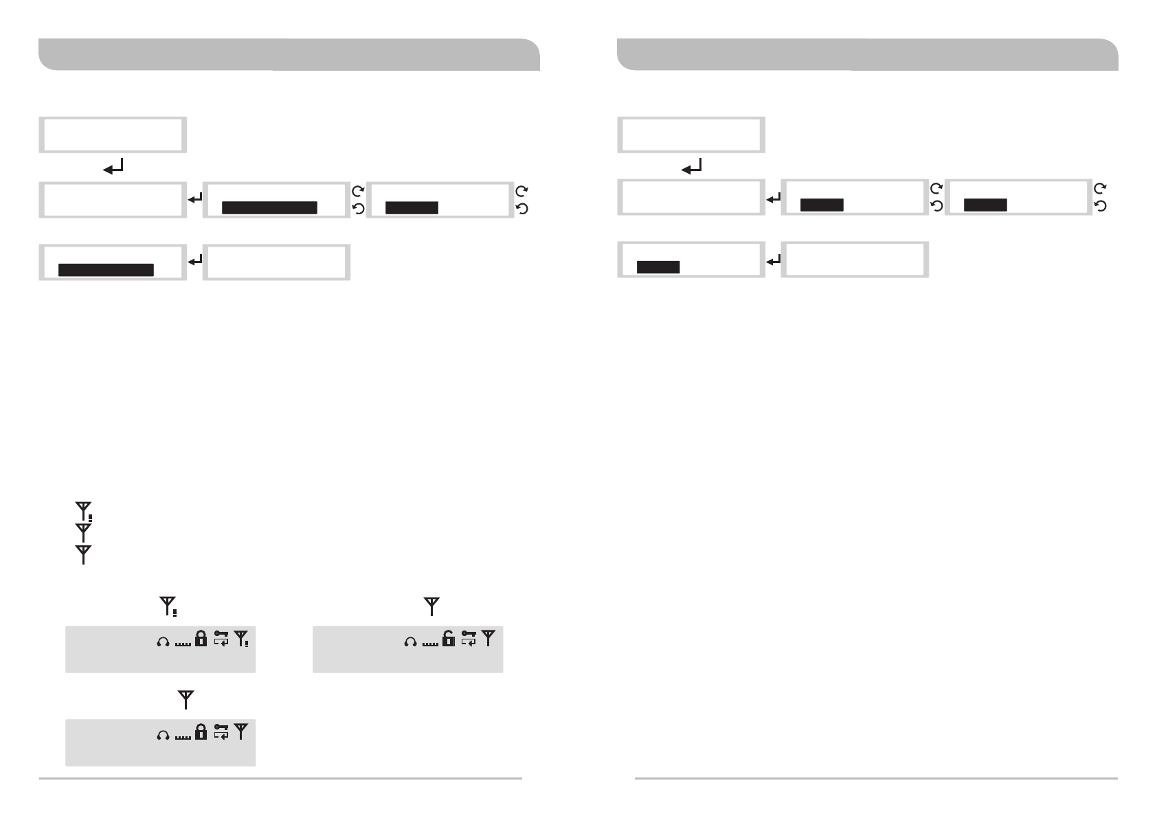
(3) RF POWER: Radio Frequency (RF) POWER Settings
10 11
> RF POWER
USER FREQUENCY
RF POWER RF POWER
> HI G H P O W E R > HI G H P O W E R
Highlighted
RF POWER
> LO W P O W E R > RF POWER
USER FREQUENCY
RF POWER
> RF O F F
A.
a. .
b.
c.
Operating Instructions:
Locate RF POWER menu, press to activate setting
Press to enter setting (highlighted in black). Turn for HIGH POWER, RF OFF or
LOW POWER. Press to save.
Once saved, indicator returns to listed menus.
Notes:
High power is country dependent. Power levels vary by region or country.
RF OFF enables no RF power emitting without powering off the transmitter.
icon: RF POWER setting is OFF.
icon: RF POWER setting is LOW.
icon: RF POWER setting is HIGH.
520.500MHz
AF
LINE
02 03
GR CH L R EQ
520.500MHz
520.500MHz
AF
MIC
AF
MIC
02 03
02 03
GR CH
GR CH
L R
L R
EQ
EQ
H
L
H
L
Highlighted
Highlighted
HIGH POWER icon
H
LOW POWER icon
L
RF OFF icon
(4) AF SENSITIVITY: Audio (AF) SENSITIVITY Settings
> AF SENSITIVITY
RF POWER
A.
a.
b.
c.
Operating Instructions:
Locate AF SENSITIVITY menu, press to activate setting.
Press to enter setting (highlighted in black). Turn for desired parameters. Press
to save.
Once saved, indicator returns to listed menus.
Notes:
Three bar indicators from the SOURCE are optimal. The red clip PEAK LED
indicates the inputs are overdriven. Reduce the level at the audio source or
change the AF sensitivity setting if 0 dB is still too high.
If less than two bar indicators from the SOURCE with -30 dB setting, change AF
INPUT to MIC LEVEL to improve AF input sensitivity level.
AF SENSITIVITY AF SENSITIVITY
> 0d B > 0 d B
AF SENSITIVITY
> -3 0 d B
AF SENSITIVITY
> -3 d B
> AF SENSITIVITY
RF POWER
.....
Highlighted Highlighted
Highlighted
Digital Stereo Rack TransmitterDigital Stereo Rack Transmitter
Highlighted
12 13
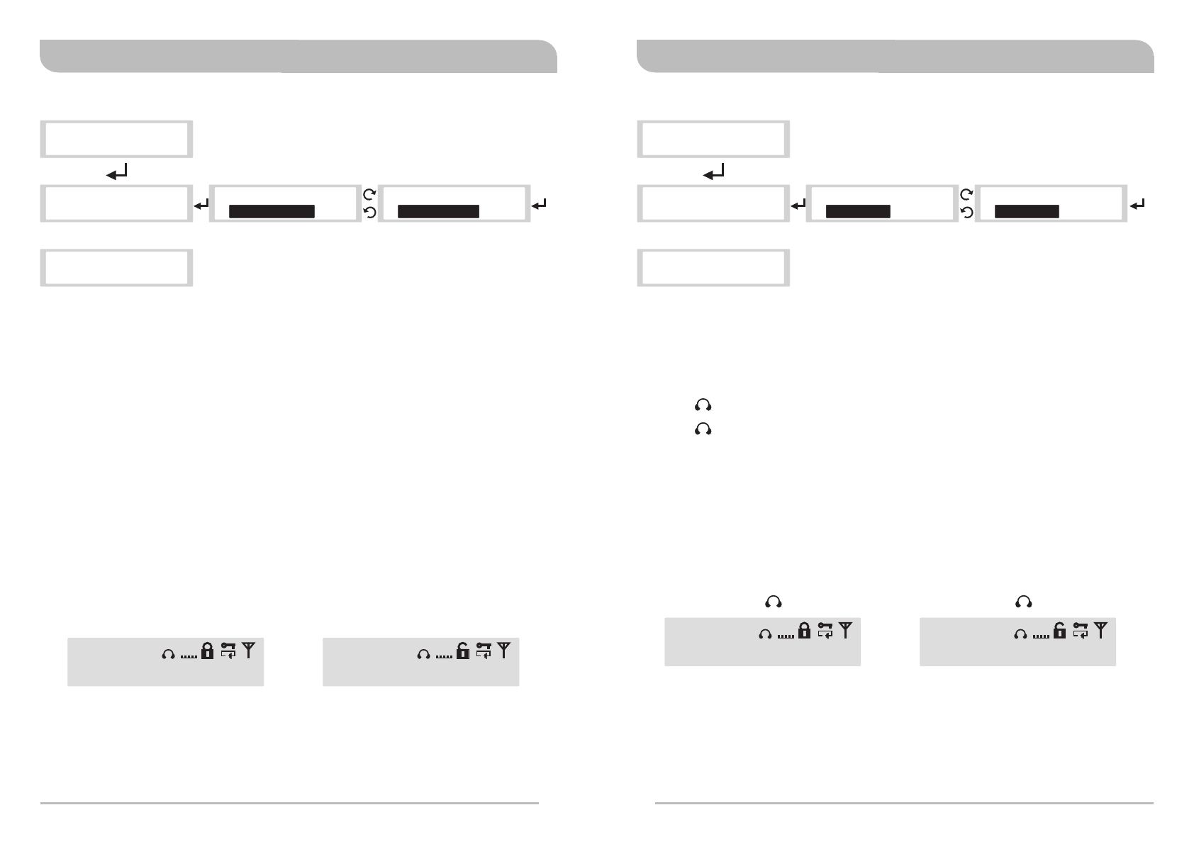
(5) AF INPUT: Audio (AF) INPUT Settings
> AF INPUT
AF SENSITIVITY
A.
a.
b.
c.
Operating Instructions:
Locate AF INPUT menu, press to activate setting.
Press to enter setting (highlighted in black). Turn for LINE LEVEL or MIC LEVEL.
Press to save.
Once saved, indicator returns to listed menus.
Notes:
Select appropriate output device with proper audio input signal strength to avoid
distortion when it is set too high and deteriorated S/N ratio when it is set too
low.
icon: MIC LEVEL.
icon: LINE LEVEL.
AF INPUT AF INPUT
> LI N E LEVEL > LINE LEVEL
AF INPUT
> MIC LEVEL
> AF INPUT
AF SENSITIVITY
AF
MIC
AF
LINE
520.500MHz
AF
LINE
02 03
GR CH L R EQ
L
520.500MHz
AF
MIC
02 03
GR CH L R EQ
L
Highlighted
MIC LEVEL icon
AF
MIC LINE LEVEL icon
AF
LINE
HighlightedHighlighted
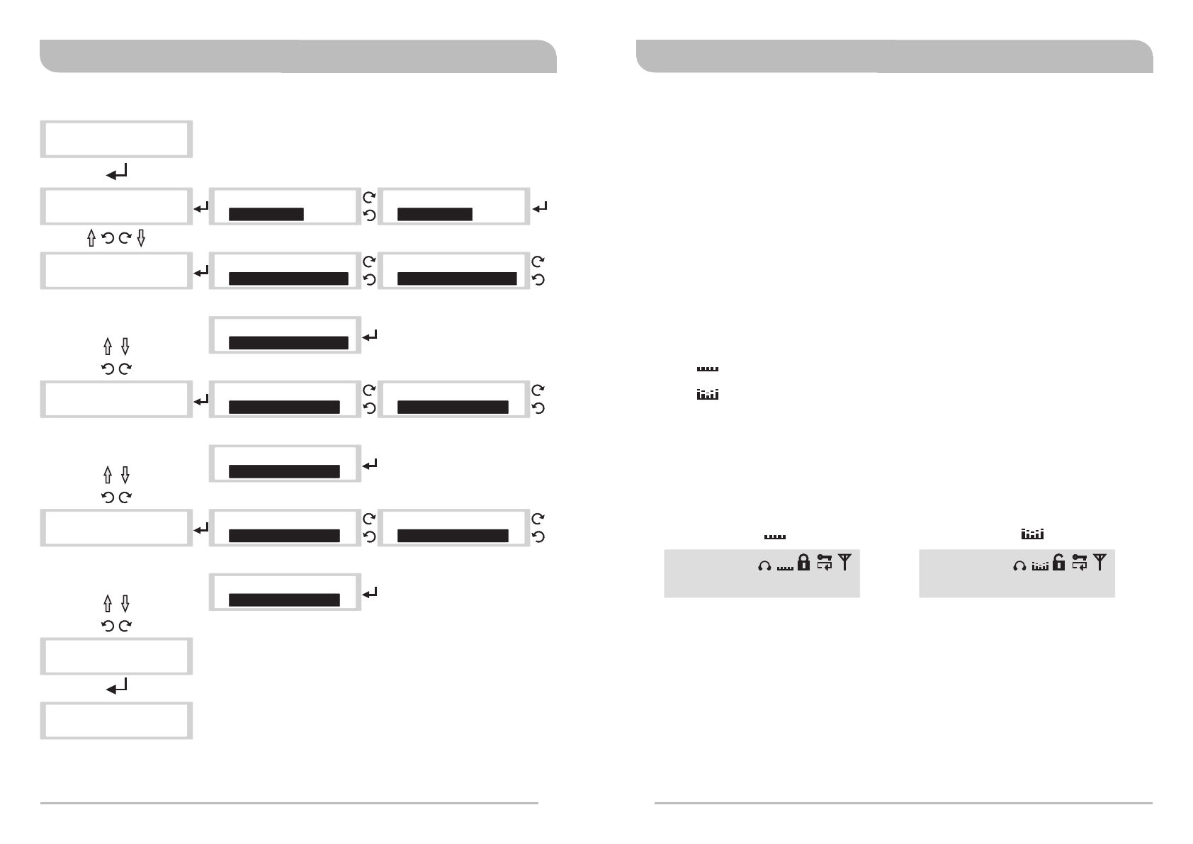
(6) SOUND MODE: SOUND MODE Settings
SOUND MODE
> ST E R E O
SOUND MODE
> STEREO
SOUND MODE
> MONO
> SOUND MODE
AF INPUT
> SOUND MODE
AF INPUT
A.
a.
b.
c.
Operating Instructions:
Locate SOUND MODE, press to activate setting.
Press to enter setting (highlighted in black). Turn for STEREO or MONO. Press to
save.
icon: STEREO.
icon: MONO.
Once saved, indicator returns to listed menus.
Note:
Plug AF IN (L) only for MONO sound.
520.500MHz
AF
LINE
02 03
GR CH L X EQ
L
520.500MHz
AF
MIC
02 03
GR CH L R EQ
L
L R
L X
STEREO icon
L R
MONO icon
L X
Digital Stereo Rack TransmitterDigital Stereo Rack Transmitter
(7) EQUALIZER: EQUALIZER Settings
14 15
.....
.....
.....
..........
> EQUALIZER
SOUND MODE
EQUALIZER
> FLAT ON
EQUALIZER
FLAT O N>
EQUALIZER
> LO W BAND=-9dB
EQUALIZER
> LOW BAND=-9dB
EQUALIZER
> LOW BAND=+9dB
EQUALIZER EQUALIZER
EQUALIZER
> MI D BAND=0dB > MID BAND=-9dB
> MID BAND=+9dB
EQUALIZER EQUALIZER
EQUALIZER
> HI BAND=+9dB > HI BAND=-9dB
> HI BAND=+9dB
EQUALIZER
> SE T E X I T
EQUALIZER
> FL AT OFF
EQUALIZER
> LOW BAND=-6dB
EQUALIZER
> MI D BAND=-6dB
EQUALIZER
> HI BAND=-6dB
SOUND MODE
> MI D BAND=+9dB
> EQUALIZER
A. Operating Instructions
a. Locate EQUALIZER, press to activate setting.
b. Press to enter setting (highlighted in black). Turn for FLAT→LOW BAND→MID
BAND→HI BAND→SET EXIT. Press to save.
FLAT: FLAT ON or FLAT OFF.
LOW BAND/ MID BAND/ HI BAND:
-9dB to +9dB: adjustable in increments of 3 dB.
SET EXIT: Press SET EXIT to return to main LCD screen.
c. Once save, press SET EXIT to return to listed menus.
Notes:
icon: FLAT ON.
icon: FLAT OFF.
520.500MHz
AF
LINE
02 03
GR CH L R
L
520.500MHz
AF
MIC
02 03
GR CH L R
L
EQ
EQ
EQ EQ
FLAT ON icon
EQ
FLAT OFF icon
EQ
Digital Stereo Rack TransmitterDigital Stereo Rack Transmitter
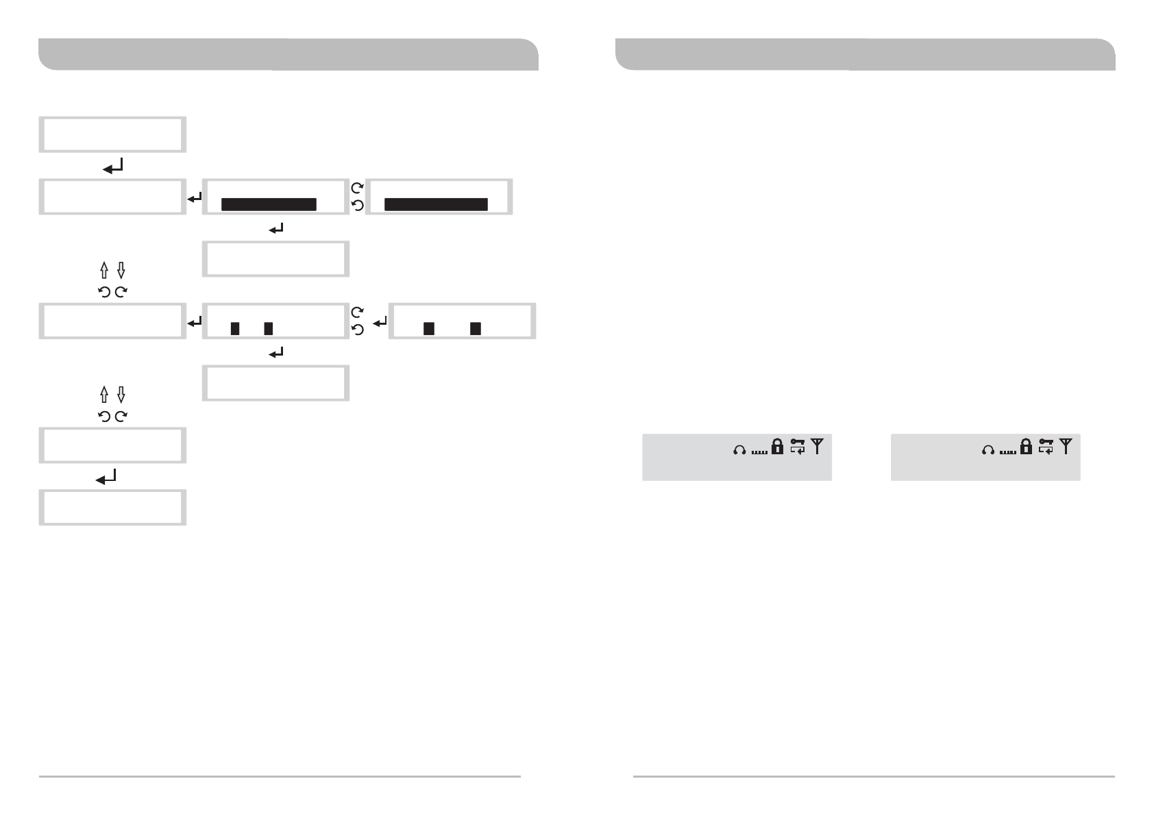
(8) NAME SETTING: NAMM SETTING Settings
NAME SETTING
> NAME SETTING
EQUALIZER
NAME SETTING
> DI S P L AY O N
NAME SETTING
> ED I T: 00MIPRO!00
NAME SETTING
> S E T E X I T
NAME SETTING
DISPLAY ON>
NAME SETTING
> DISPLAY ON
NAME SETTING
DISPLAY OFF>
EQUALIZER
> M I D BAND=+9dB
> NAME SETTING
> KL NO 00 IPRO!00M M
NAME SETTING
0 0> . / 12 0 MIPRO!00
NAME SETTING
> ED I T: 00MIPRO!00
+
16 17
.....
A. Operating Instructions
a. Locate NAME SETTING menu, press to activate setting.
b. Press to enter setting (highlighted in black). Turn for DISPLAY ON
→EDIT: 00MIPRO!00 →SET EXIT.
DISPLAY: Turn for DISPLAY ON or DISPLAY OFF.
EDIT: Up to 10 alphanumeric characters and symbols.
SET EXIT: Press SET EXIT to return to main LCD screen.
c. Once save, press SET EXIT to return to listed menus.
Note:
DISPLAY ON – Alphanumeric characters are shown.
DISPLAY “ON”
Displays alphanumeric characters
DISPLAY “OFF”
Display User Frequency
00MIPRO!00
AF
MIC
02 03
GR CH L R
L
EQ
520.500MHz
AF
MIC
02 03
GR CH L R
L
EQ
Digital Stereo Rack TransmitterDigital Stereo Rack Transmitter
18 19
(9) NET ADDRESS Settings: For PC control network
A. Operating Instructions:
a. Interface with ACT-BUS for pc-control network. Can monitor up to 64 channels.
b. 01~64 transmitter addresses can be setup and monitor via an optional PC-
control software remotely. All transmitters must be connected to a dedicated
address for network identification.
c. Locate NET ADDRESS menu, press to activate setting.
d. Press to enter setting (highlighted in black). Press to save.
e. Once saved, indicator returns to listed menus.
> NET ADDRESS
NAME SETTING
NET ADDRESS
> 01
NET ADDRESS
> 01
> NET ADDRESS
NAME SETTING
NET ADDRESS
> 64
.....
NET ADDRESS
> 02
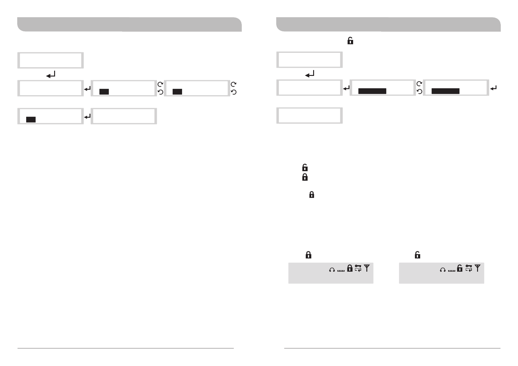
(10) SET LOCK Settings : For front panel lock
> SET LOCK
NET ADDRESS
> SET LOCK
NET ADDRESS
SET LOCK
> UN L O C K
SET LOCK
> UNLOCK
A. Operating Instructions:
a. Locate SET LOCK menu, press to activate setting.
b. Press to enter setting (highlighted in black) for UNLOCK or LOCK. Press to save.
icon: UNLOCK.
icon: LOCKED.
c. Once save, press to return to listed menus.
d. Once icon appears the panel is locked. No new settings can be changed.
Need to unlock the panel first prior to make new setting changes.
520.500MHz
AF
LINE
02 03
GR CH L R EQ
L
icon: LOCKED icon: UNLOCK
520.500MHz
AF
LINE
02 03
GR CH L R EQ
L
SET LOCK
> LOCK
Digital Stereo Rack TransmitterDigital Stereo Rack Transmitter
20 21
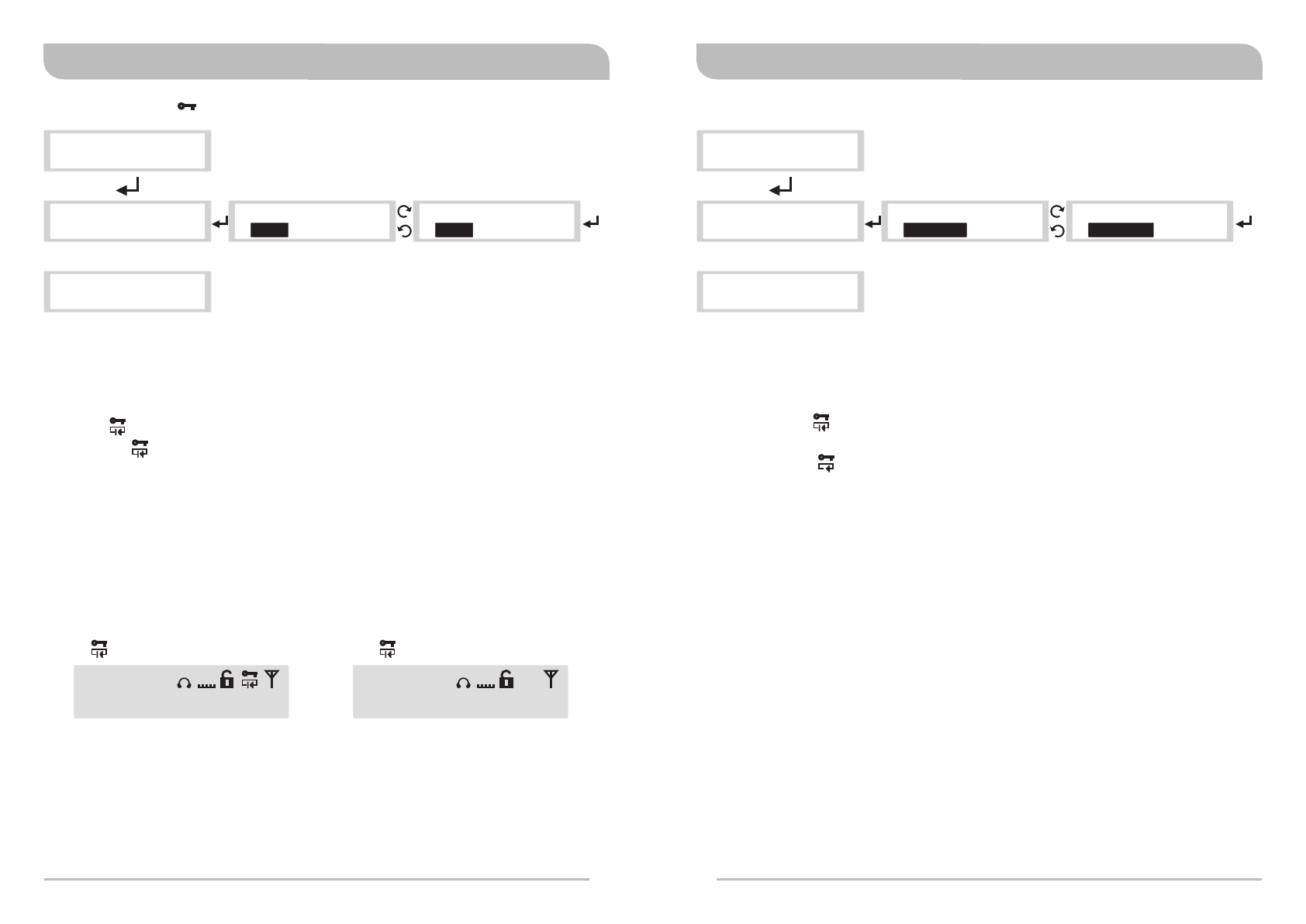
(11) ENCRYPTION : To add encryption or decryption
> ENCRYPTION
> ENCRYPTION
SET LOCK
SET LOCK
> OF F
ENCRYPTION
> OFF
ENCRYPTION
A. Operating Instructions:
a. Locate ENCRYPTION menu, press to activate setting.
b. Press to enter setting (highlighted in black) for ON or OFF. Press to save.
icon: Encryption key is ON
No icon: Encryption key is OFF (not activated)
c. Once save, press to return to listed menus.
** Be sure to press ACT button for synchronization from transmitter to
bodypack receiver after each time an Encryption is activated.
d. After a new encryption key is added to the transmitter, the transmitter frequency
is no longer valid and compatible with existing bodypack receivers. To be
compatible, perform the ACT sync function.
ENCRYPTION
> ON
520.500MHz
AF
LINE
02 03
GR CH L R EQ
L
520.500MHz
AF
LINE
02 03
GR CH L R EQ
L
icon: ENCRYPTION ON No icon: ENCRYPTION OFF
(12) SECURE KEY Settings: Adding encryption key option
> SECURE KEY
> SECURE KEY
ENCRYPTION
ENCRYPTION
A. Operating Instructions:
a. Locate SECURE KEY menu, press to activate setting.
b. Press to enter setting (highlighted in black) for STATIC or SCROLL. Press to save.
STATIC icon: No new encryption key is generated each time the ACT sync
button is pressed.
SCROLL icon: A new encryption key is generated each time the ACT sync
button is pressed.
c. Once save, press to return to listed menus.
d. 128bit encryption key is generated randomly and very difficult to break or crack
for eavesdropping occurrences.
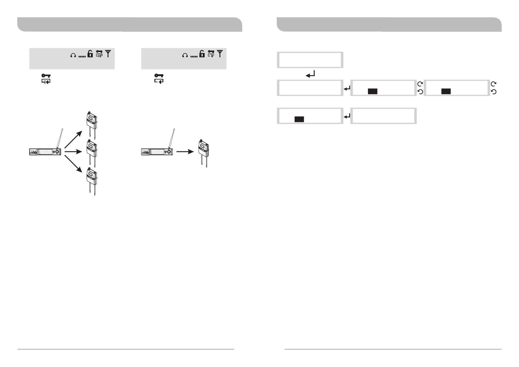
Notes:
STATIC encryption method is ideal for one transmitter to multiple receivers.
SCROLL encryption method is ideal for one transmitter to one receiver.
> STATIC > STAT I C
SECURE KEY SECURE KEY
> S C R O L L
SECURE KEY
Digital Stereo Rack TransmitterDigital Stereo Rack Transmitter
22 23
520.500MHz
AF
LINE
02 03
GR CH L R EQ
L
SCROLL: new encryption
icon
STATIC: existing encryption
520.500MHz
AF
LINE
02 03
GR CH L R EQ
L
Transmitter
SCROLL encryption mode is
ideal for a single receiver
Receiver
RX1
RX2
RX3
STATIC encryption mode is
ideal for multiple receivers
icon
Transmitter
Receiver
(13) FREE SCAN Settings: SCAN for an interference-free transmitter channel
> FREE SCAN
SECURE KEY
> FREE SCAN
SECURE KEY
> 0 1 01 5 1 2 . 000MHz > 01 512.000MHz 01
FREE SCAN FREE SCAN
A. Operating Instructions:
a. Locate FREE SCAN menu, press to activate setting.
b. Press to enter setting (highlighted in black). Turn left or right to scan for an
open Channel within the specified Group. Press to save.
c. Once save, press to return to listed menus.
d. FREE SCAN scans for an interference-free channel within the specified Group
only.
e. Use FREE SCAN to analyze the RF environment for interference and identify
available frequencies. During scanning process the transmitter stops
transmission. When no interference-free channel is located, it reverses
automatically back to the original channel.
Note: When performing a FREE SCAN
Turn on potential sources of interference such as other wireless systems or
devices, computers, CD players, large LED panels, effects processors, and
digital rack equipment so they are operating as they would be during the
presentation or performance (so the scan will detect and avoid any
interference they generate).
FREE SCAN
> 0 1 502.125MHz 08
.....
FREE SCAN
> 01 502.125MHz 02
Digital Stereo Rack TransmitterDigital Stereo Rack Transmitter
24 25
520.500MHz
AF
LINE
02 03
GR CH L R EQ
L
< 30cm (12 in.)
What is ACT ?
1. ACT is short for Automatic Channel Targeting. ACT is a proprietary sync technology
developed first by MIPRO in the professional audio industry. Consequently, ACT sync
has become an industry-standard for fast, easy and precise frequency
synchronization between transmitter and receiver.
Features
1. Frequency do not require an external tool for adjustment.
2. Precise and fast synchronization.
3. Frequency is synchronized and saved and ready for repeat usage.
Operating Instructions?
1. Press the ACT sync button on the rack transmitter to start the synchronization.
2. ACT SYNC word with moving “….” appears on the rack transmitter screen.
3. Align the ACT sync windows of both receiver & transmitter within 30cm.
4. ACT SYNC word with moving “…”disappears during a successful sync and returns
back to main LCD screen.
5. ACT FAIL appears during a failed sync.
6. Repeat step 1 to 5.
MIPRO's Proprietary ACT Sync Function
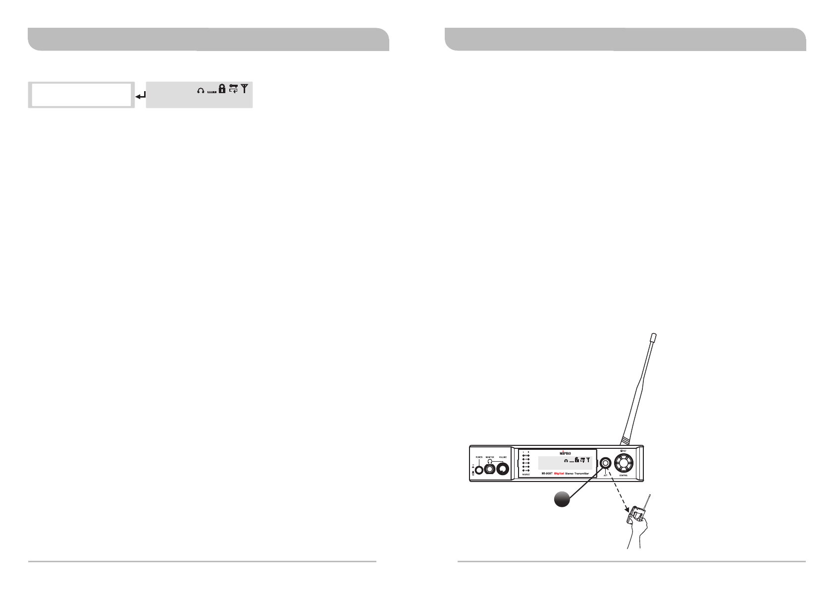
(14) EXIT & SAVE Settings: Save changes and exit
> & SAVEEXIT
FREE SCAN
A. Operating Instructions:
a. Press to exit and return to the main LCD screen.
520.500MHz
AF
MIC
02 03
GR CH L R EQ
L
Press sync
button to synchronize
frequency & encryption
key to bodypack
receiver.
ACT
Digital Stereo Rack TransmitterDigital Stereo Rack Transmitter
Press ACT sync button
ACT FAIL appears during a failed synchronization
A. Operating Instructions:
a. Press the ACT sync button on the transmitter to activate the synchronization.
b. Align the ACT sync windows of both transmitter and receiver within 30cm
(12-inch) and 10 seconds.
c. During syncing, the transmitter LCD screen display is flashing "ACT SYNC ...” .
d. If synchronization is done successfully, the transmitter LCD return to the main
screen.
e. If synchronization is done unsuccessfully, it displays SYNC FAIL. Repeat steps 1-4
until is done successfully.
** During ACT sync, the frequency is synchronized from transmitter to receiver.
Other setting as an encryption key (SCROLL or STATIC) is also synchronized
during the transfer.
(14) ACT Synchronization
26 27
512.000MHz
AF
LINE
01 01
GR CH L R EQ
L
> 01 01 5 1 2 . 000MHz
> 01 01 5 1 2 . 000MHz
ACT SYNC . . . . . . . .
ACT FAIL
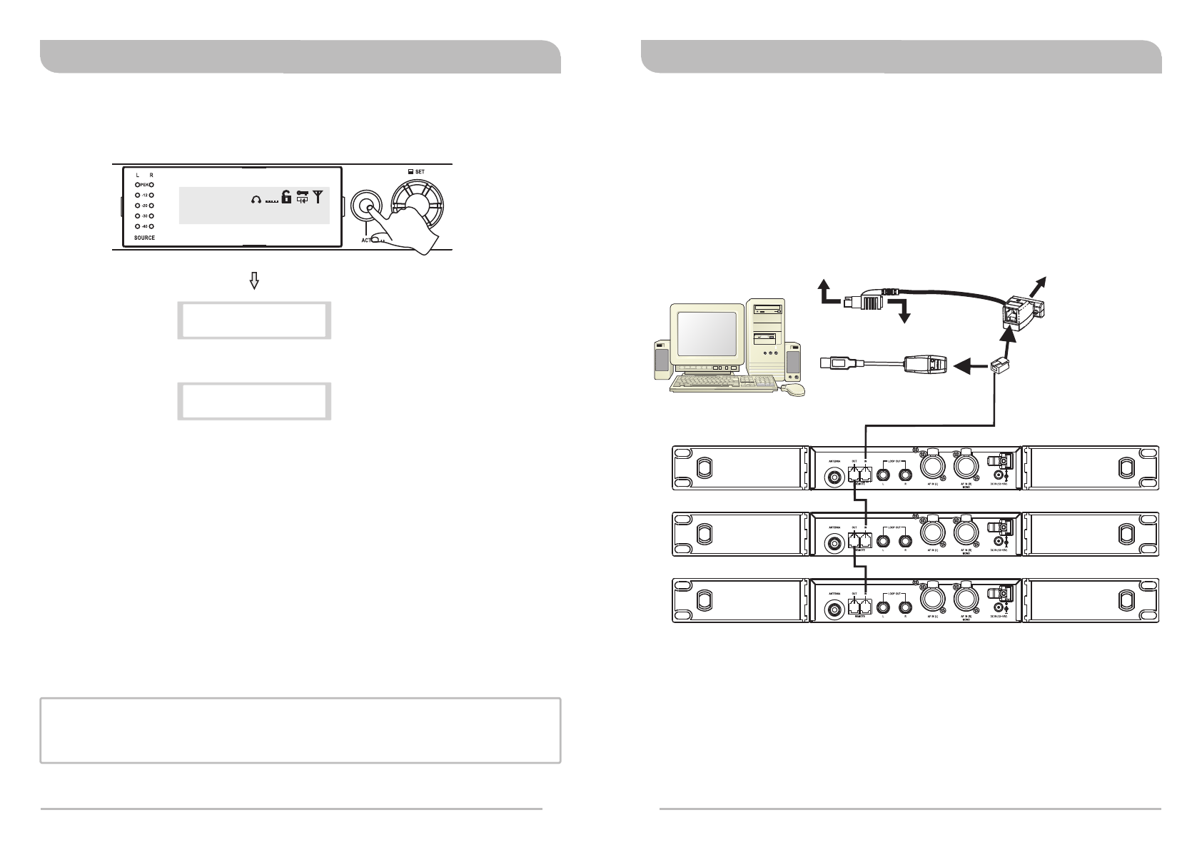
Network Interface
1. See connection diagram below for connection from REMOTE connectors located at the
rear panel of the transmitter via RS-232 or USB connection to RS-232 COM PORT or
USB PORT.
Wiring Instructions
TX1
TX2
TX3
Network Connection
MIPRO DVU
MIPRO DVJ
OR
PC
Connect to RS-232 jack on PCConnect to keyboard jack on PC
Connector of keyboard
should plug in here
Connect to USB
jack on PC
1. Connect REMOTE OUT to REMOTE IN of another transmitter for interconnection of
other transmitters. First transmitter (TX) 1, connect REMOTE IN to a MIPRO-DV.
2. Up to 64 transmitters can be linked and connected.
3. Up to 300 meters of internet connection is possible. However, we recommend for up
to 100 meters to ensure optimal performance and quality of high-speed
transmission.
During Synchronization…
Digital Stereo Rack TransmitterDigital Stereo Rack Transmitter
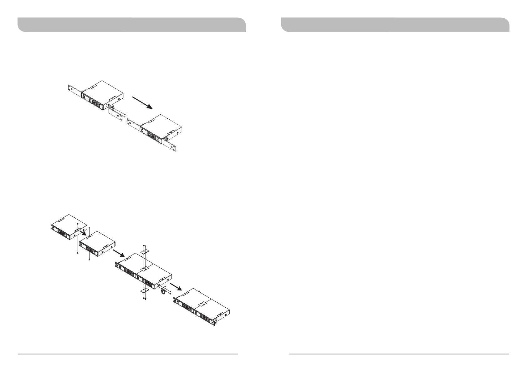
Rack-mounting a 1/2 rack unit
!Rack-mount with an optional FB-71 rack-mount kit and fasten accordingly.
Rack-mounting two 1/2 rack units side-by-side
!Remove top & bottom screws.
!Insert top and bottom plates to joint two transmitters. Fasten screws.
!Rack-mount with an optional FB-72 rack-mount kit.
28 29
Rackmount Kit Cautions Recommendations&
!Do not use the same frequency bands when mixing MIPRO IEM and MIPRO wireless
microphone systems to avoid potential interferences.
!When using RG-58 or 3D cable, do not exceed 5 meters and use 50Ω coaxial cable to
transmit signals to the external antenna.
!If possible, maintain line-of-sight between transmitter and receivers for optimal
reception quality during outdoor or indoor performances. Indoor reception quality tend
to degrade due to obstacles and objects absorbing radio waves making the reception
distance shorter compared with outdoor performances.
!Power supply voltage should not be less than 12V and not higher than 15V. Ensure at
least 500mA or more output current. Deficient current causes operating voltage
instability or malfunction and exceeding current causes shorter the product life cycle
and possible short or damaging circuits.
!
!
Note
Refer to actual product in the event of product description discrepancy.
Frequency range and maximum deviation comply with the regulations of different
countries.
Digital Stereo Rack TransmitterDigital Stereo Rack Transmitter