Mipro Electronics Co MT-90 Wireless Mixer User Manual MA909 2CE194
Mipro Electronics Co Ltd Wireless Mixer MA909 2CE194
Contents
- 1. Users Manual Part 1
- 2. Users Manual Part 2
- 3. Users Manual Part 3
Users Manual Part 3
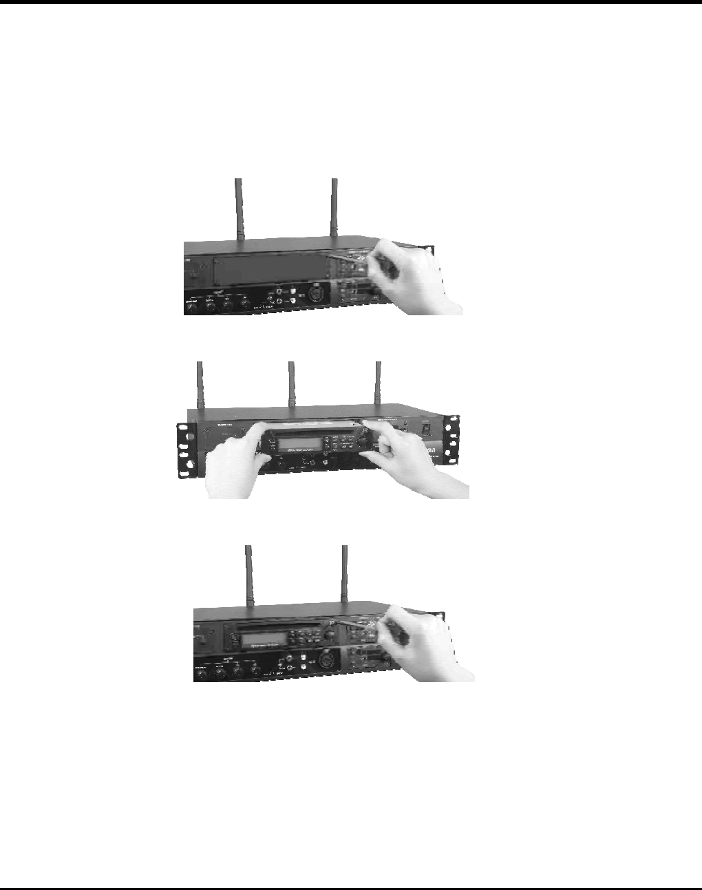
2installation:.CDPlayer
A.
B.
C.
Removescrewsholdingtheblankpanelandremovethepanel(seeFig.3-1)
InserttheCDplayerintothemixer(seeFig.3-2)
Reinstallscrewstosecuretheplayer(seeFig.3-3)
-8-
OperatingManual
WIRELESSMIXER
Fig.3-1
Fig.3-2
Fig.3-3
3.OperationNotesandPrecautions:
ModelNumber MA-909
ReceiverModule AcceptsoneortwoMRM-70UHFACTreceivermodules
MatchingTransmitters Handheld:ACT-707HE,Bodypack:ACT-707TE
Antennas Locatedonrearpanel
CDPlayer Built-inanti-shockmechanism
Balanced/UnbalancedMIC&LINE-IN/LINE-OUT
5.2
50Hz-15KHz±3dB
16frequenciesintheUHF600MHzband
<0.5%
Built-in90~264VACswitchingpowersupply
420(L)x44(H)x200(D)
Black
AudioInputJacks
T.H.D.
FrequencyResponse
WirelessTransmitter
PowerSupply
Dimensions(m/m)
Weight(kg)
ExteriorColor
1.Microphoneshavepriorityovermusicinputs.Whenmusicisplayinganda
microphonereceivesanaudiosignal,themusicwillbemuted.Assoonasthereis
nolongeranaudiosignaltothemicrophone,themusicwillfadein.
2.Althoughthesamefrequencybandmaybeused,itisimportantthatthefrequencyof
theMT-90transmitterandtheMRM-70receivermodulearenotthesame.Otherwise,
theMA-909willnotoperateproperly.
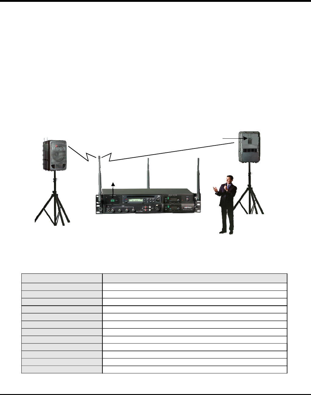
3.AllaudiosourcestotheMA-909willbetransmittedviatheMT-90transmittertoany
MR-90receiverequippedactivespeaker.PleaserefertoattachedFigures.
Activespeakersystem Highfidelitywirelessinterlinking
receivermodule
Built-inhighfidelity
wirelessinterlinking
transmitter
Professionalwirelessmixerunit.
-9-
4.Specifications :
OperatingManual
WIRELESSMIXER
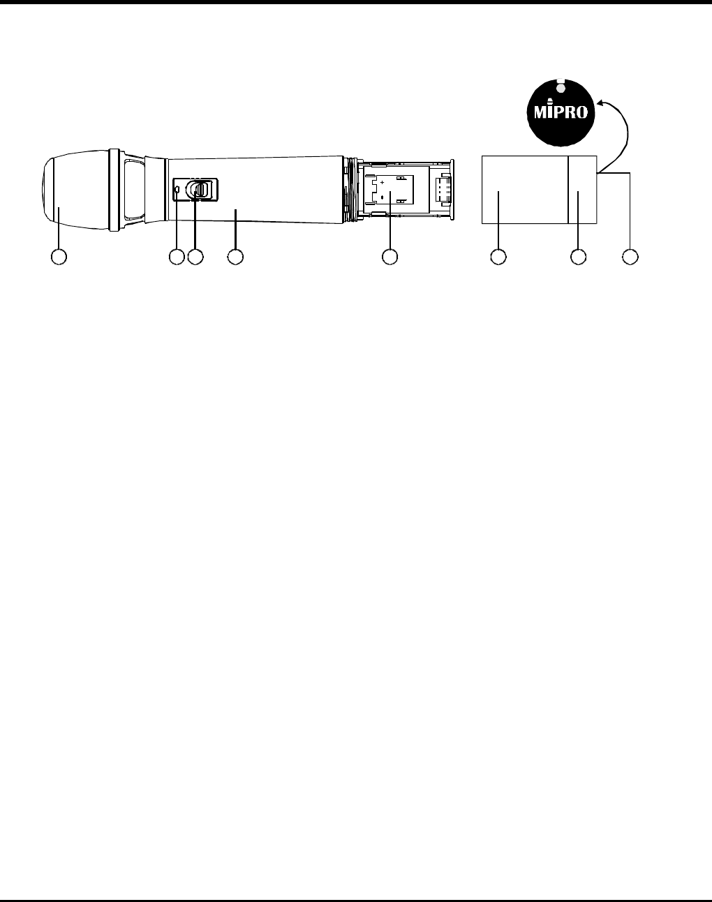
HANDHELDWIRELESSMICROPHONE
1 2 3 4 5 6 7 8
-10-
OperatingManual
1.PARTNAMESANDFUNCTIONS
1.Grill:Protectscartridge,prevents"POP"noiseandpreventsmicrophonefromrollingwith
polygonalshape.
2.BatteryStatusIndicator:Indicatespoweron/offandthebatterystatus.Whenthepower
switchisturnedON,theredLEDindicatorflashesbriefly,indicatingnormalbatterystatus.
Ifnoflashoccurs,theunithasnobatteryinstalledorthebatteryiseitherdischargedor
installedincorrectly.Iftheindicatorremainslitafterpowerup,thebatteryisweakand
shouldbereplaced.
3.PowerOn/OffSwitch:Slidetheswitchtoturnpower"ON"or"OFF".
4.MicrophoneHousing
5. BatteryCompartment:Accommodatesone9-Voltbattery.
6.BatteryCompartmentCover
7.EndRing:Anoptionalcolorringmaybeinstalledheretoidentifymultipletransmitters.
8.ACTSensor:ReceivesACTsignalstoautomaticallyprogramthemicrophonefrequency.
(Fig.1)
-11-
HANDHELDWIRELESSMICROPHONE
OperatingManual
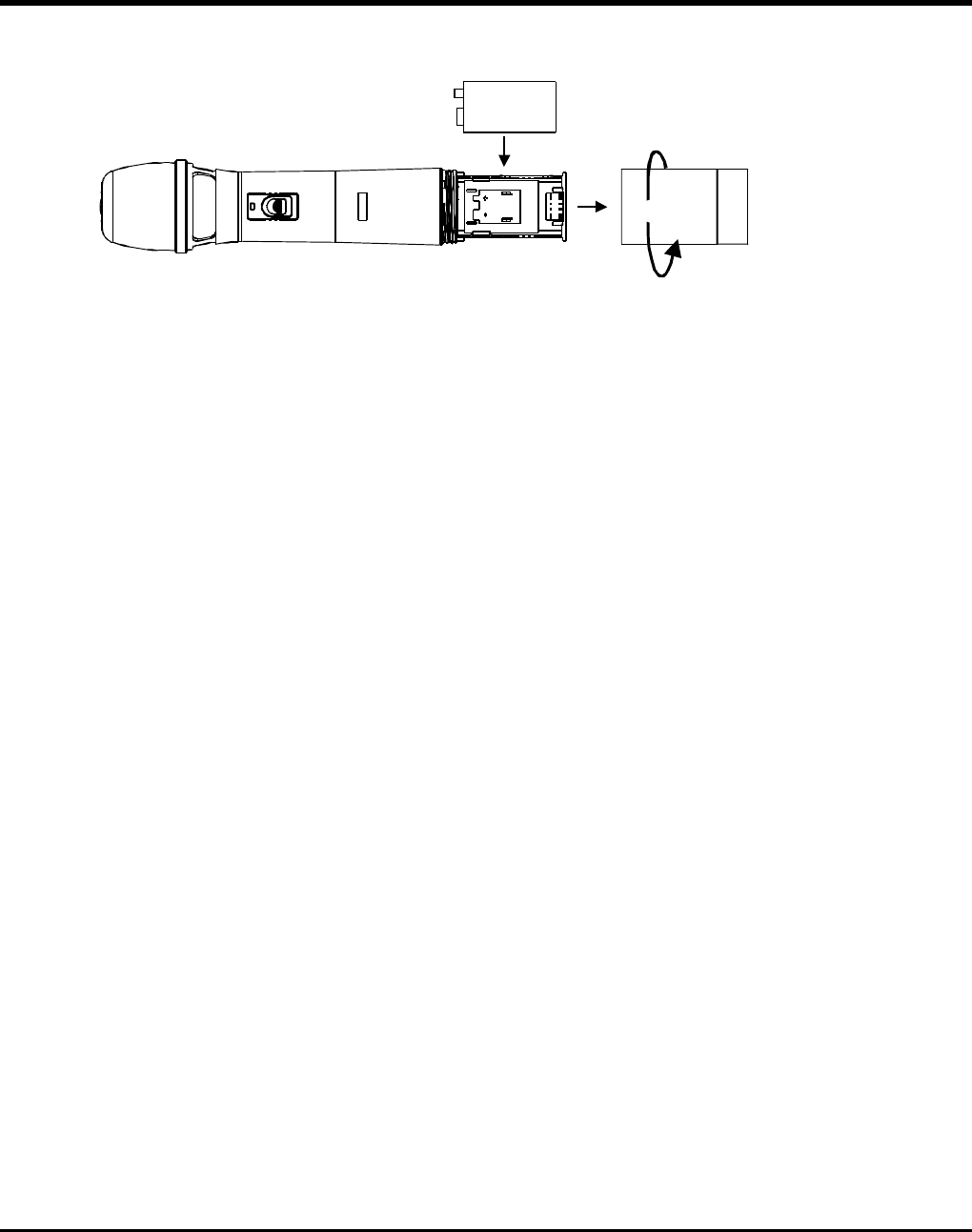
(Fig.2)
1.Unscrewthebatterycap(6)inacounter-clockwisedirection.
2.Inserta9-voltbatteryintothebatterycompartment(5),observingthecorrectpolarityas
showninFig.2.Themomentthebatterytouchestheterminals,theindicator(2)willflash
briefly,indicatingcorrectpolarity.However,ifnoflashoccurs,eitherthepolarityis
incorrectorthebatteryisdead.Pleasere-insertthebattery,observingitscorrectpolarity,
orexchangeitforafreshbattery.
2. BATTERYINSTALLATION
3. OPERATINGINSTRUCTIONS
1. Whenthemicrophoneisswitchedon:
Theindicatorwillflashbrieflyindicatingnormaloperation.
2.Duringuse:
TheAFLEDindicatoronthereceiverwillilluminateaccordingtotheaudiosignalstrength
fromthemicrophone.
3.Whenthemicrophoneisnotinuse:
Makesurethatyouturnoffthemicrophonetoextendbatterylife.Removethebattery
fromthebatterycompartmentifthemicrophoneisnottobeusedagainforsometime.If
arechargeablebatterywasused,takeitoutandrechargeit.
Undernormaloperation,whenreceiverandtransmitter(mic)arepairedtogethertoaset
frequency,themicrophoneindicator(2)willremainoffafterACTsetsupthefrequency.
However,iftheindicator(2)isflashing,itmeansthereceiverandtransmitter(mic)arenotin
thesamefrequencyband.
Pleasecheckthestickersonthetransmitter(mic)andreceivertoverifythatthe
frequencybandsmatch.
4.CAUTIONS
1
2
3
5
8
7
4
6
9
10
ACT
-12-
BODYPACKTRANSMITTER
OperatingManual
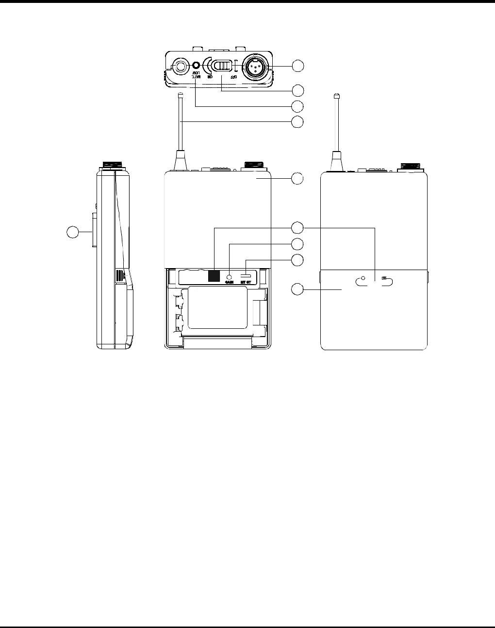
1.PARTNAMESANDFUNCTIONS
()Fig.1
1.MICInputJack:Connectstoeitheralavaliereorheadsetmicrophone.(SeeSection3for
connectiondetails)
2.PowerSwitch:SwitchtoONpositionforoperation.SwitchtoOFFpositionwhennotin
use.
3.BatteryStatusIndicator(red):Indicatespoweron/offandbatterystatus.
(a)Whenpowerswitchisturnedon:TheLEDindicatorflashesbriefly,indicatingnormal
batterystatus.
(b)WhentheLEDindicatorremainslitateitherpoweronorduringusage:Thebattery
levelislowandreplacementisnecessary.
4.Antenna:1/4-wavetransmittingantenna.
5.TransmitterHousing
6.ACTSensor:ReceivestheACTsignaltoautomaticallyprogramthetransmitterfrequency.
7.GainControl:Adjuststhemicrophoneinputgain.
8.GT/MTLevelSelectSwitch:SwitchtoGTpositionforinstrumentusageand"LineIn".
Gaincontrolisdisabledin"GT"mode.Switchto"MT"formicrophoneusage.Thegain
controlwilladjusttheinputsensitivityin"MT"mode.
-13-
BODYPACKTRANSMITTER
OperatingManual
9.BatteryCompartmentandCover:Accommodatesone9-Voltbattery.
10.DetachableBeltClip:Allows360degreerotationtosuittransmittingangles.Todetach
simplyuseascrewdriverata45degreeangle(seediagram).
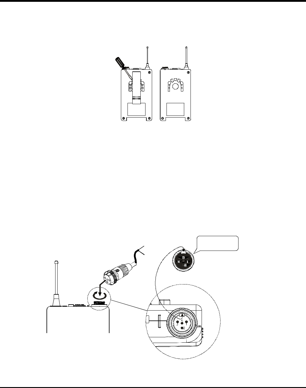
1.ToadjustGT/MTSwitch(8),andGainControl(7),simplypushdownbothsnaplockson
thesidesofbatterycoverandflipitbackwardstoexposetheadjustmentpanel.
2.Toturnonthebodypack,slidethepowerswitchtotheonposition.
3.TheLEDindicatorflashesbrieflywhenpoweronindicatingnormalbatterystatus.Ifno
flashoccursiteitherhasnobattery,thebatteryisdrained,orinstalledincorrectly.
Changeaccordingly.
4.Plugthemicrophoneconnectorintotheinputjack(1)andtightentheconnectorscrewby
turningclockwiseasshownin(Fig.2).
2. OPERATINGINSTRUCTIONS
(Fig.2)
Lavalier
Headset
Lineuptheraisedlineon
theconnectorwiththe
slotinthejackandinsert
CapsuleConnector
AUDIO
SHIELD
4
3
2
1
PIN
SHIELD
AUDIO
BIAS
3
4
PIN
1
2
AUDIO
SHIELD 1
4
3
2
PIN
SHIELD
AUDIO
3
2 1 PIN
4
3
2
1
SHIELD
AUDIO
1
3
4
2
PIN
1 3
4
2
1 3
4
2
1 3
4
2
1 3
4
2
13
4
2
-14-
BODYPACKTRANSMITTER
OperatingManual
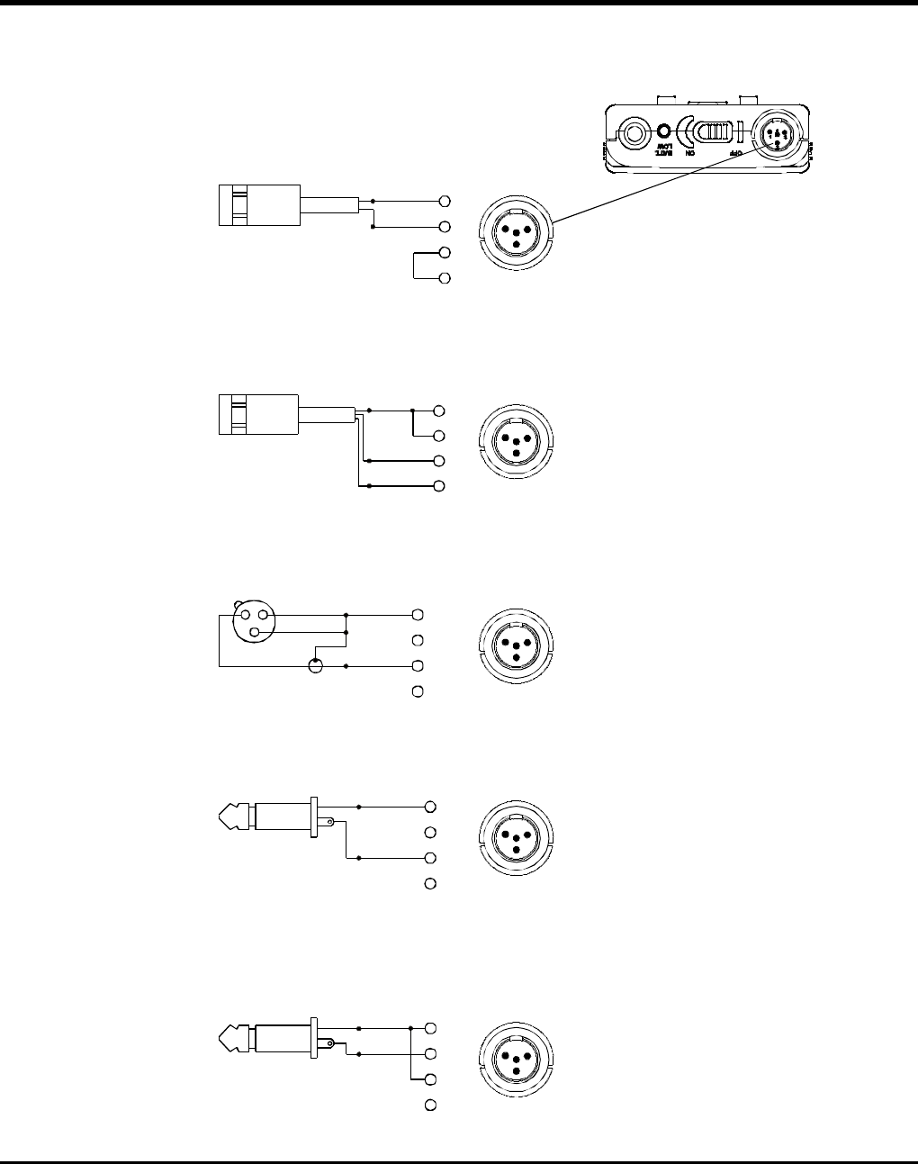
3. AF4-PININPUTCONNECTIONMETHOD
(1)2-WireElectretCondenserMicrophoneCapsule
(2)3-WireElectretCondenserMicrophoneCapsule
(3)DynamicMicrophone
(4)ElectricGuitar
(5)Line-in(Impedance8KATT.10dB)
-15-
BODYPACKTRANSMITTER
OperatingManual
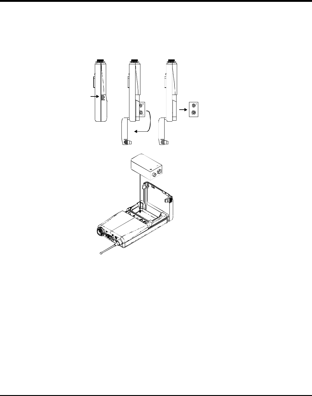
4. BATTERYINSTALLATION
1.Pushdownbothsnap-locksonthesidesofbatterycovertoopen(Fig.3).
2.Inserta9-voltbatteryintothebatterycompartmentobservingthecorrectpolarityas
shownin(Fig.4).ThenclosethebatterycompartmentasshowninFig.4).
(Fig.3)
(Fig.4)
Note:Whenthemicrophoneisnotinuse:
Makesurethepowertothemicrophoneisswitchedoff.Ifthemicrophonewillnotbe
usedforsometime,pleaseremovethebatteriesfromthebatterycompartmenttoavoid
batteryleakagethatcoulddamagebatteryspringsandcircuitry.
Undernormaloperation,whenreceiverandtransmitter(mic)arepairedtogethertoaset
frequency,themicrophoneindicator(2)willremainoffafterACTsetsupthefrequency.
However,iftheindicator(2)isflashing,itmeansthereceiverandtransmitter(mic)arenotin
thesamefrequencyband.
Pleasecheckthestickersonthetransmitter(mic)andreceivertoverifythatthe
frequencybandsmatch.
5.CAUTIONS
BODYPACK TRANSMITTER
Operating Manual
Notice:
The changes or modifications not expressly approved by the party responsible for
compliance could void the user's authority to operate the equipment.
IMPORTANTNOTE:
To comply with the FCC RF exposure compliance requirements, no change to the
antenna or the device is permitted. Any change to the antenna or the device could
result in the device exceeding the RF exposure requirements and void user's
authority to operate the device.
Federal Communication Commission Interference Statement ~
This equipment has been tested and found to comply with the limits for a Class B digital device, pursuant to
Part 15 of the FCC Rules. These limits are designed to provide reasonable protection against harmful
interferencein a residentialinstallation. .
This equipment generates, uses and can radiate radio frequency energy and, if not installed and used in
accordance with the instructions, may cause harmful interference to radio communications. However, there is
no guarantee that interference will not occur in a particular installation. If this equipment does cause harmful
interference to radio or television reception, which can be determined by turning the equipment off and on, the
user is encouraged to try to correct the interference by one of the following measures:
.Reorient or relocate the receiving antenna.
.Increase the separation between the equipment and receiver.
.Connect the equipment into an outlet on a circuit different from that to which the receiver is connected.
.Consult the dealer or an experienced radiorrV technician for help.
i
,\
This device complies with Part 15 of the FCC Rules. Operation is subject to the following two conditions:
(1) This device may not cause harmful interference, and (2) This device must accept any interference received,
including interference that may cause undesired operation.
-16 -

2CE194
ElectronicsCo.,Ltd.
Headoffice:814,Pei-KangRoad,Chiayi,600,Taiwan.
Taipeioffice:5,Lane118,Sung-tehRoad,110,Taiwan.
Web-http://www.mipro.com.tw
E-mail:@mipro.com.tw
Taipei,
mipro