Mircom Group of Companies NC-211 Zigbee Repeater User Manual LT 2074 MiCare Installation Manual
Mircom Group of Companies Zigbee Repeater LT 2074 MiCare Installation Manual
UserManual.wiki
>
Mircom Group of Companies
>
NC 211 User Manual
User Manual
Navigation menu
Upload a User Manual
Namespaces
Wiki Guide
HTML
PDF
Info
Views
User Manual
Discussion / Help
Navigation
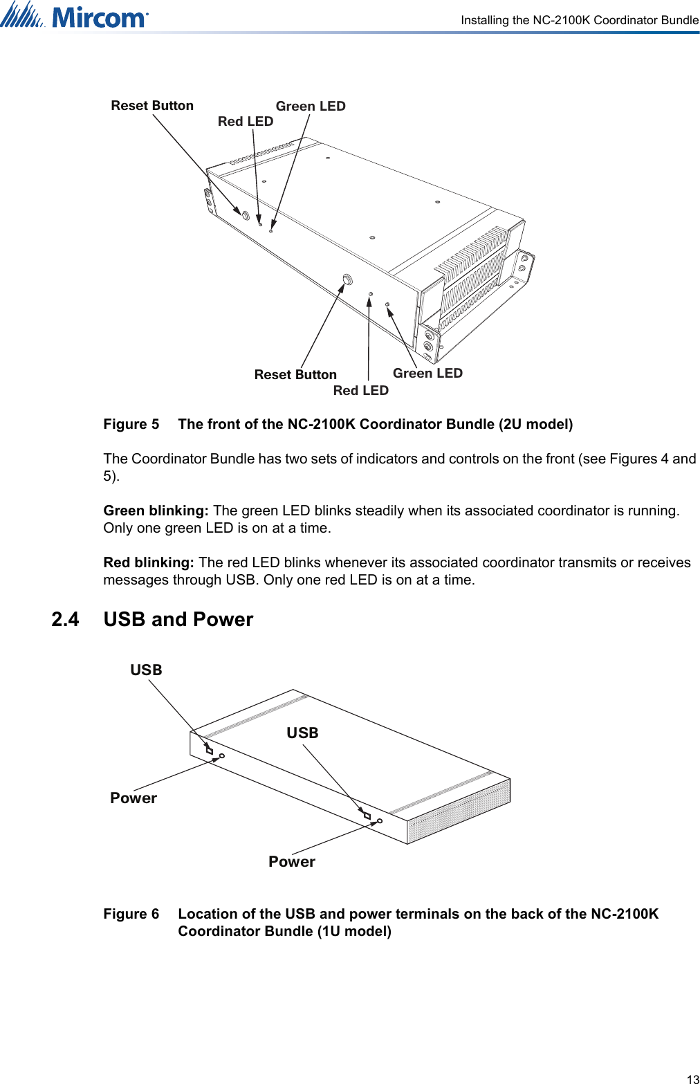
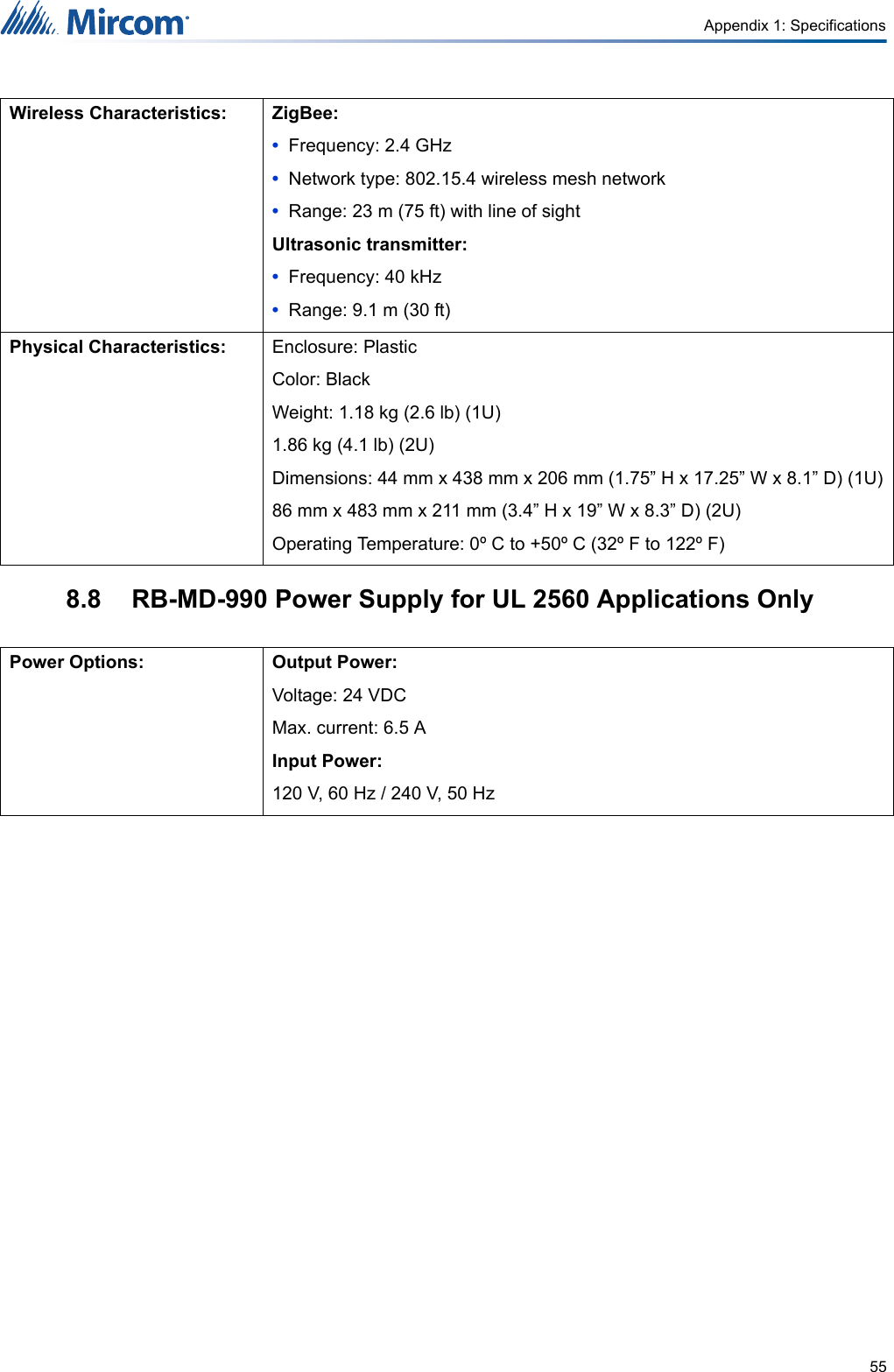
![57836%$&.8332:(5&225',1$725%81'/(1&.6(59(552209'&3RZHU6XSSO\5%0'0L&DUH6HUYHU(TXLSPHQWZ1&6:&20/2:+,*+2XWSXW2XWSXW2XWSXW2XWSXW,QSXW*1',QSXW*1',QSXW*1',QSXW*1'1&&121&&121&&12 1&&122XWSXW2XWSXW2XWSXW2XWSXW*1'5HG$PEHU*UHHQ:KLWH%URZQ3LQ3LQ&1/LQH,Q&1([W&1 &1&1&1&19'&:DOO$GDSWHU9$&9'&:DOO$GDSWHU9$&86%&RQQHFWLRQ86%&RQQHFWLRQ:LUH7\SH$:*:LUH7\SH$:* :LUH7\SH$:*7R$GGLWLRQDO1&V1&'RPH/LJKW836%$&.8332:(5836%$&.8332:(59$&836%$&.8332:(5(/(&75,&$/5220/$/$ /$/$ /$/$5P"EEJUJPOBM/$/$T1&1&1&1&*+]=LJEHH:LUHOHVV&RQQHFWLRQ/(*(1'+DUG:LUHG&RQQHFWLRQ1RWH1&1&DQG1&DUHEDWWHU\SRZHUHG10.0 Appendix 3: Wiring Diagram for Emergency Call System (UL 2560)](https://usermanual.wiki/Mircom-Group-of-Companies/NC-211/User-Guide-3768284-Page-57.png)
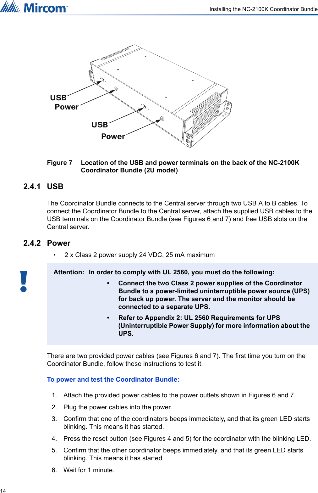
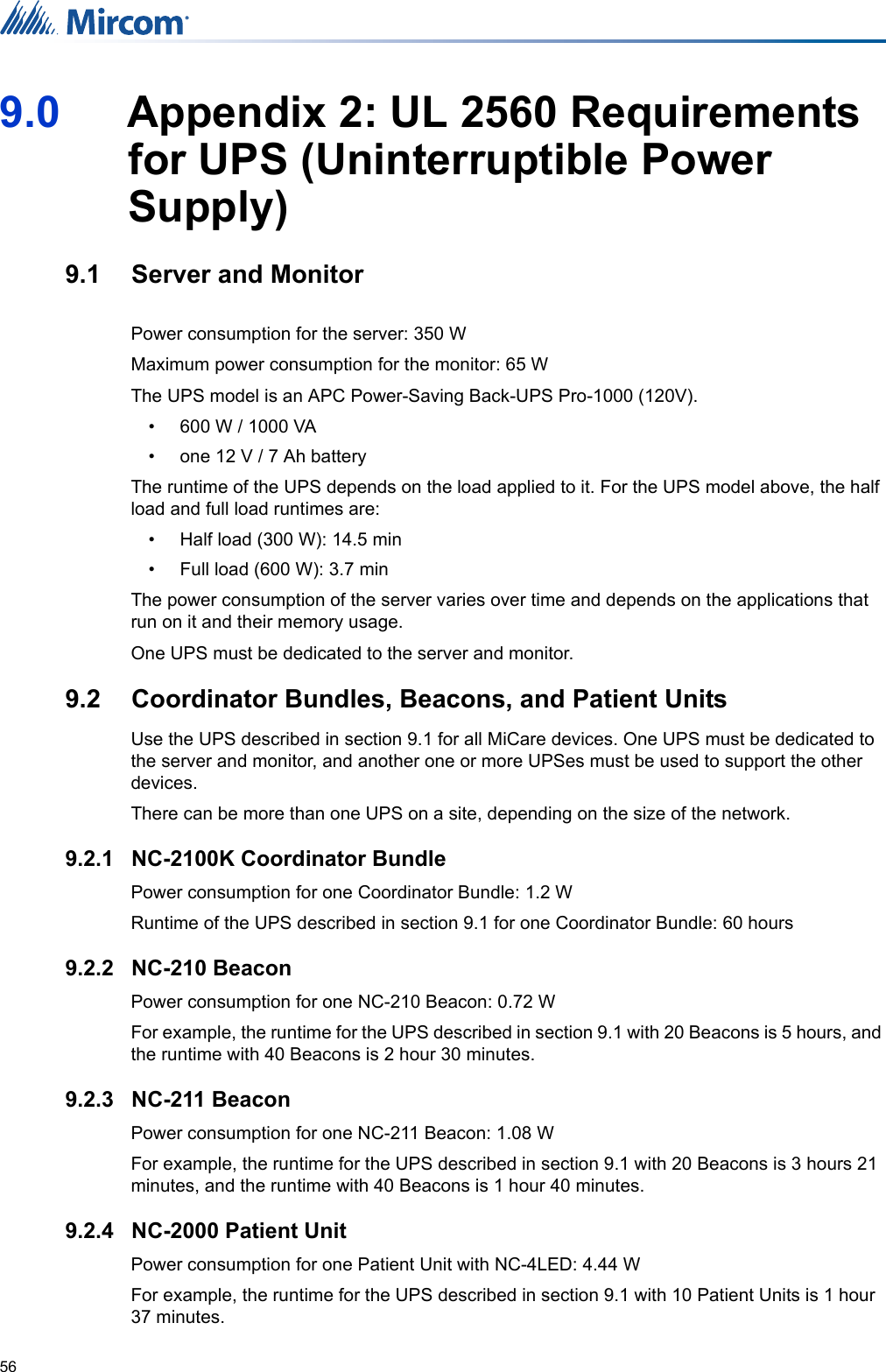
![58&225',1$725%81'/(1&.6(59(552201856(52200L&DUH6HUYHU(TXLSPHQWZ1&6:&20/2:+,*+2XWSXW2XWSXW2XWSXW2XWSXW,QSXW*1',QSXW*1',QSXW*1',QSXW*1'1&&121&&121&&12 1&&122XWSXW2XWSXW2XWSXW2XWSXW*1'5HG$PEHU*UHHQ:KLWH%URZQ3LQ3LQ&1/LQH,Q&1([W&1 &1&1&1&19'&:DOO$GDSWHU9'&:DOO$GDSWHU9$&86%&RQQHFWLRQ86%&RQQHFWLRQ:LUH7\SH$:*1&'RPH/LJKW/$/$ /$/$ /$/$1&1&1&1&*+]=LJEHH:LUHOHVV&RQQHFWLRQ/(*(1'9$& 9$& 9$&9'&+DUG:LUHG&RQQHFWLRQ1RWH1&1&DQG1&DUHEDWWHU\SRZHUHG11.0 Appendix 4: Wiring Diagram for Nurse Call System (UL 1069)](https://usermanual.wiki/Mircom-Group-of-Companies/NC-211/User-Guide-3768284-Page-58.png)