Mircom Group of Companies NC-211 Zigbee Repeater User Manual LT 2074 MiCare Installation Manual
Mircom Group of Companies Zigbee Repeater LT 2074 MiCare Installation Manual
User Manual

Installation Manual LT-2074 Rev. 3.9.1
February 2018
Nurse Call and Emergency System

3
Table of Contents
1.0 Introducing the MiCare Nurse Call and Emergency System 6
1.1 Overview of the MiCare Nurse Call and Emergency System ........................................ 7
1.2 Contact Us ..................................................................................................................... 9
2.0 Installing the NC-2100K Coordinator Bundle 10
2.1 Overview ........................................................................................................................ 11
2.2 Dimensions .................................................................................................................... 11
2.3 LEDs .............................................................................................................................. 12
2.4 USB and Power ............................................................................................................. 13
2.5 Mounting ........................................................................................................................ 15
2.6 Maintenance and Service .............................................................................................. 15
3.0 Installing the NC-2000 Patient Unit 16
3.1 Overview ........................................................................................................................ 17
3.2 Telephone Connections ................................................................................................. 18
3.3 Inputs ............................................................................................................................. 20
3.4 Dome Lights and Generic Outputs ................................................................................. 21
3.5 Paging Input ................................................................................................................... 25
3.6 Bed Cords ...................................................................................................................... 26
3.7 Secondary Ultrasound Transmitter ................................................................................ 27
3.8 Power ............................................................................................................................. 27
3.9 Mounting the Patient Unit ............................................................................................... 29
3.10 LED Status Indicators .................................................................................................... 30
3.11 Maintenance and Service .............................................................................................. 31
3.12 Restarting the Patient Unit ............................................................................................. 31
4.0 Installing the NC-210/NC-211 Beacon 32
4.1 Overview ........................................................................................................................ 33
4.2 NC-210 ........................................................................................................................... 33
4.3 NC-211 ........................................................................................................................... 34
4.4 Installing the Beacon ...................................................................................................... 37
4.5 Maintenance and Service .............................................................................................. 37
5.0 Installing the NC-103 Pull Station 38
5.1 Overview ........................................................................................................................ 39
5.2 Input ............................................................................................................................... 40
5.3 Power ............................................................................................................................. 40
5.4 Mounting the Pull Station ............................................................................................... 40
5.5 LED Status Indicator and Beeper .................................................................................. 41
5.6 Maintenance and Service .............................................................................................. 42

4
6.0 Installing the NC-220 ZF3 43
6.1 Overview ........................................................................................................................ 44
6.2 Inputs ............................................................................................................................. 44
6.3 Power ............................................................................................................................. 45
6.4 Mounting the ZF3 ........................................................................................................... 45
6.5 Maintenance and Service ............................................................................................... 45
7.0 Installing The NC-500 Pendant 46
7.1 Overview ........................................................................................................................ 47
7.2 LED Status Indicator ...................................................................................................... 47
7.3 Using the Pendant .......................................................................................................... 48
7.4 Canceling the Message from the Pendant ..................................................................... 48
7.5 Maintenance and Service ............................................................................................... 48
8.0 Appendix 1: Specifications 50
8.1 NC-2000 Patient Unit ..................................................................................................... 50
8.2 NC-210 Beacon .............................................................................................................. 51
8.3 NC-211 Beacon .............................................................................................................. 52
8.4 NC-103 Pull Station ........................................................................................................ 52
8.5 NC-220 ZF3 3 Input Transmitter (auxiliary device for supplementary operation) .......... 53
8.6 NC-500 Pendant ............................................................................................................ 54
8.7 NC-2100K Coordinator Bundle ...................................................................................... 54
8.8 RB-MD-990 Power Supply for UL 2560 Applications Only ............................................ 55
9.0 Appendix 2: UL 2560 Requirements for UPS
(Uninterruptible Power Supply) 56
9.1 Server and Monitor ......................................................................................................... 56
9.2 Coordinator Bundles, Beacons, and Patient Units ......................................................... 56
10.0 Appendix 3: Wiring Diagram for Emergency Call
System (UL 2560) 57
11.0 Appendix 4: Wiring Diagram for Nurse Call System
(UL 1069) 58
12.0 Appendix 5: Device Installation Table 59
13.0 Warranty and Warning Information 61
14.0 Special Notices 64

5
List of Figures
Figure 1 A two-bed suite with some typical Nurse Call and Emergency System devices installed 8
Figure 2 Dimensions of the NC-2100K Coordinator Bundle (1U model) ...................................... 11
Figure 3 Dimensions of the NC-2100K Coordinator Bundle (2U model) ...................................... 12
Figure 4 The front of the NC-2100K Coordinator Bundle (1U model) .......................................... 12
Figure 5 The front of the NC-2100K Coordinator Bundle (2U model) .......................................... 13
Figure 6 Location of the USB and power terminals on the back of the NC-2100K Coordinator
Bundle (1U model) ......................................................................................................... 13
Figure 7 Location of the USB and power terminals on the back of the NC-2100K Coordinator
Bundle (2U model) ......................................................................................................... 14
Figure 8 NC-2100K (1U model) mounted to a wall ...................................................................... 15
Figure 9 NC-2100K (2U model) mounting holes .......................................................................... 15
Figure 10 The front of the NC-2000 Patient Unit ............................................................................ 17
Figure 11 Telephone interface terminals CN1 and CN2 ................................................................ 18
Figure 12 Input connections on CN6 .............................................................................................. 20
Figure 13 Dome light connections on terminal CN16 ..................................................................... 21
Figure 14 NC-4LED connections on terminal CN16 ...................................................................... 23
Figure 15 Generic output connections on terminal CN13. ............................................................. 24
Figure 16 External paging input terminal CN2 ............................................................................... 25
Figure 17 Paging amplifier - 25 V output ........................................................................................ 25
Figure 18 Paging amplifier - 75 V output ........................................................................................ 26
Figure 19 Bed cord input terminal CN3 .......................................................................................... 26
Figure 20 External ultrasonic emitter terminal CN14 ..................................................................... 27
Figure 21 Power terminal CN11 and jumpers J3 and J4 ............................................................... 28
Figure 22 Battery terminal CN8 ...................................................................................................... 29
Figure 23 Patient Unit mounting plate ............................................................................................ 30
Figure 24 The front of the NC-210 Beacon .................................................................................... 33
Figure 25 The front of the NC-211 Beacon .................................................................................... 34
Figure 26 NC-211 (back view) ....................................................................................................... 35
Figure 27 JW1 on NC-211 ............................................................................................................. 36
Figure 28 The front of the NC-103 Pull Station .............................................................................. 39
Figure 29 Pull Station mounting plate ............................................................................................ 41
Figure 30 Input terminals TS1 and TS2 on the NC-220 ZF3. ........................................................ 45
Figure 31 The front of the NC-500 Pendant ................................................................................... 47
Figure 32 Use a small screwdriver to open the case ..................................................................... 48
Figure 33 Pendant with bottom half of case removed .................................................................... 49

6
1.0 Introducing the MiCare Nurse Call
and Emergency System
This chapter gives you a brief introduction to the MiCare Nurse Call and
Emergency System, its application, and the types of devices that make up the
Nurse Call and Emergency System.
In this chapter you will find:
•Overview of the MiCare Nurse Call and Emergency System
•Contact Us

7
Introducing the MiCare Nurse Call and Emergency System
1.1 Overview of the MiCare Nurse Call and Emergency System
The MiCare Nurse Call and Emergency System from Mircom is an advanced nurse call
solution that couples wireless mesh networking technology with ultrasonic signalling to
accurately identify and respond to emergency events. To achieve this, the Nurse Call and
Emergency System uses the highly reliable 802.15.4 wireless network. This network
technology provides a self-forming, self-healing mesh type transport when routing messages
to and from the Nurse Call and Emergency System Central server.
There are three types of devices that make up the Nurse Call and Emergency System:
•Coordinators: Coordinators connect to the Nurse Call and Emergency System Central
server through a USB connection. They communicate on the 802.15.4 wireless network
but are not programmed with the MiCare Nurse Call and Emergency System firmware.
Their sole purpose is to transport messages back and forth between the Central server
and the routers on the 802.15.4 wireless network.
•Routers: Routers communicate with the Central server through the coordinators on the
Nurse Call and Emergency System. They are programmed with the MiCare Nurse Call
and Emergency System application firmware. Routers also listen for messages from
end devices on the system, which they then pass on to the Central server. Finally,
routers come with ultrasound transmitters that are used to locate portable MiCare end
devices.
•End Devices: End devices send messages about their status wirelessly to the 802.15.4
network. They do not communicate directly with the Central server. Their messages are
instead passed on to the Central server through a router on the network. End devices
are not programmed with the Nurse Call and Emergency System application firmware.
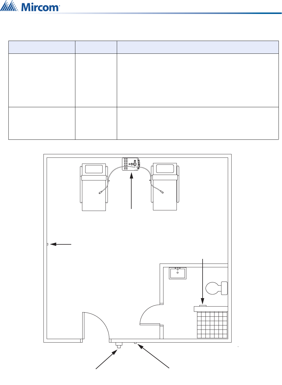
Figure 1 shows a typical Nurse Call and Emergency System installation in a two-bed suite.
This installation includes examples of both routers and end devices.
Table 1 Devices in the Nurse Call and Emergency System
Device Type Description
NC-2100K
Coordinator Bundle Coordinator
The Coordinator Bundle passes messages between the
routers and the Central server in the Nurse Call and
Emergency System.
NC-2000 Patient Unit Router
The Patient Unit is ideally suited for patient rooms. Some of
its features include inputs for 2 bed cords, two-way voice
communication, an ultrasound transmitter, and outputs for 4-
light dome lights, such as the NC-4LED corridor light.
NC-210 and NC-211
Beacon Router
The Beacon is used to extend the range of a Patient Unit or
for use in areas where a Patient Unit is not required (for
example, a hallway). It has an ultrasound transmitter for
locating end devices.
NC-103 Pull Station End Device
The Pull Station is a battery powered transmitter with a pull
cord, 3 buttons, and an external input. These features make
the Pull Station an ideal accessory to the Patient Unit,
providing emergency call capability in areas where a Patient
Unit is not required or feasible.
8
Introducing the MiCare Nurse Call and Emergency System
Figure 1 A two-bed suite with some typical Nurse Call and Emergency System devices
installed
Not shown in Figure 1 is the NC-2100K Coordinator Bundle and the computers running the
Dashboard application at the nurse stations.
NC-220 ZF3 End Device
The ZF3 is a battery powered transmitter with 3 inputs (one
cancel button and two general purpose inputs) that can be
used anywhere inputs (for example, door contacts, motion
sensors, or auxiliary smoke detectors) need to be monitored.
When an input becomes active the ZF3 sends the
information wirelessly to the coordinator and the monitoring
software.
NC-500 Pendant End Device
The Pendant is a battery powered transmitter with one
button. The Pendant is the only mobile device in the network
and has an ultrasonic receiver for locating purposes, in
addition to ZigBee capabilities.
Table 1 Devices in the Nurse Call and Emergency System
Device Type Description
+
NC-2000
Patient Unit
NC-220
ZF3 NC-103
Pull Station
NC-210
Beacon
Dome Lights

9
Introducing the MiCare Nurse Call and Emergency System
Coordinators are usually installed in a server room with the Central server.
Each nurse station has a computer with a browser connected to the Dashboard application on
the Central server. The Dashboard application shows alerts that are raised by MiCare devices
and plays an audible indication to notify nurses of alerts. Speakers must be installed on all
computers running Dashboard.
This manual contains information on how to install the routers, end devices, and coordinators
that make up the Nurse Call and Emergency System.
For information on how to configure the Nurse Call and Emergency System, see LT-2075, the
MiCare Nurse Call and Emergency System Administrator’s Guide.
For information on how to use the Nurse Call and Emergency System, see LT-2076, the
MiCare Nurse Call and Emergency System User Guide.
1.2 Contact Us
1.2.1 Canada and USA
Toll Free: 1-888-660-4655
Local: 905-660-4655
Fax: 905-660-4113
1.2.2 Website
http://www.mircom.com
Attention: In order to comply with UL 2560, the audible signal at the computers
must be at least 60 dBA at a distance of one meter. Speakers MUST be
connected to all computers running Dashboard.
In order to comply with UL 1069, the heartbeat of all the devices must be
1 minute.
!

10
2.0 Installing the NC-2100K Coordinator
Bundle
The NC-2100K Coordinator Bundle is the heart of the Nurse Call and
Emergency System. It passes messages between the routers and the Central
server in the Nurse Call and Emergency System. This chapter provides an
overview of the Coordinator Bundle and its connections.
In this chapter you will find the following:
•Overview
•LEDs
•USB and Power
•Mounting
•Maintenance and Service
11
Installing the NC-2100K Coordinator Bundle
2.1 Overview
There are 2 models of the NC-2100K Coordinator Bundle:
• 1U model
• 2U model
The 2 models differ only in enclosure size, mounting brackets, and position of the LEDs and
buttons.
The NC-2100K Coordinator Bundle connects directly to the Central server through USB and is
responsible for the communication between the wireless routers and the Central server.
The Coordinator Bundle contains two coordinators. Only one coordinator operates at a time,
and the other coordinator is on standby. If one coordinator stops working, the second
coordinator takes over.
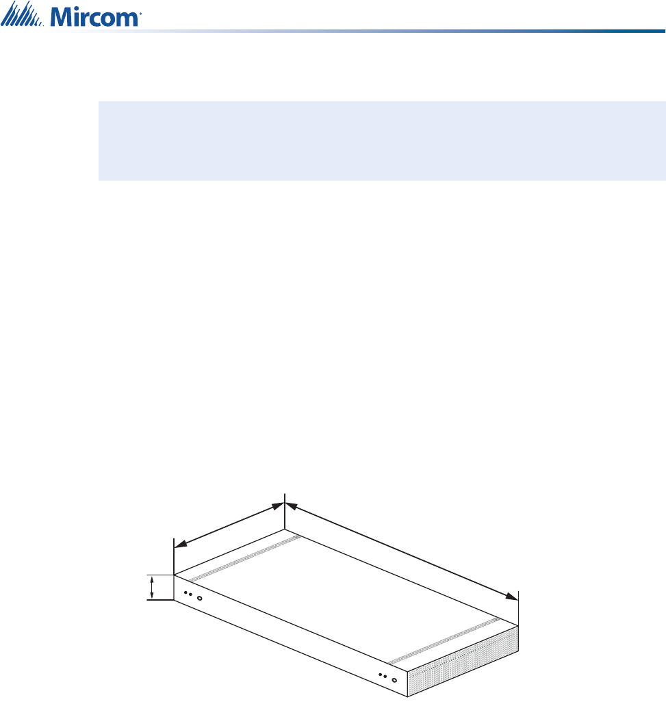
2.2 Dimensions
Figure 2 Dimensions of the NC-2100K Coordinator Bundle (1U model)
Install in accordance with the Canadian Electrical Code or the National Electrical
Code, and comply with all local regulations. Final acceptance subject to the Local
Authority Having Jurisdiction (AHJ).
!
438 mm
(17 1/4”)
206 mm
(8 3/32”)
44 mm
(1 3/4”)
12
Installing the NC-2100K Coordinator Bundle
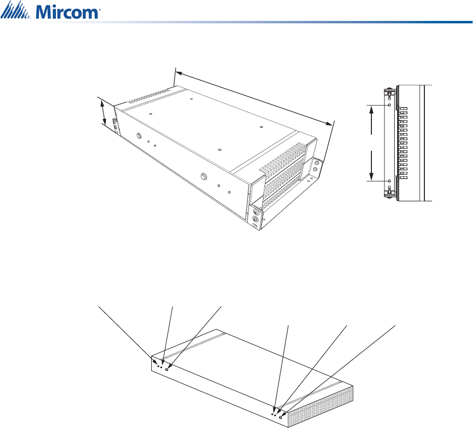
Figure 3 Dimensions of the NC-2100K Coordinator Bundle (2U model)
2.3 LEDs
Figure 4 The front of the NC-2100K Coordinator Bundle (1U model)
86 mm
(3 25/64”)
483 mm
(19 1/64”)
152 mm
(6”)
Green LED Red LED Reset Button
Green LED Red LED Reset Button
13
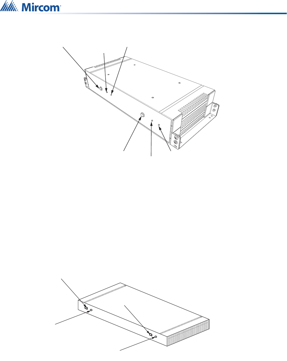
Installing the NC-2100K Coordinator Bundle
Figure 5 The front of the NC-2100K Coordinator Bundle (2U model)
The Coordinator Bundle has two sets of indicators and controls on the front (see Figures 4 and
5).
Green blinking: The green LED blinks steadily when its associated coordinator is running.
Only one green LED is on at a time.
Red blinking: The red LED blinks whenever its associated coordinator transmits or receives
messages through USB. Only one red LED is on at a time.
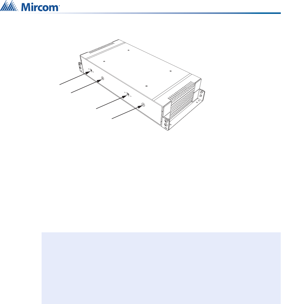
2.4 USB and Power
Figure 6 Location of the USB and power terminals on the back of the NC-2100K
Coordinator Bundle (1U model)
Reset Button
Red LED
Green LED
Reset Button Green LED
Red LED
USB
USB
Power
Power
14
Installing the NC-2100K Coordinator Bundle
Figure 7 Location of the USB and power terminals on the back of the NC-2100K
Coordinator Bundle (2U model)
2.4.1 USB
The Coordinator Bundle connects to the Central server through two USB A to B cables. To
connect the Coordinator Bundle to the Central server, attach the supplied USB cables to the
USB terminals on the Coordinator Bundle (see Figures 6 and 7) and free USB slots on the
Central server.
2.4.2 Power
• 2 x Class 2 power supply 24 VDC, 25 mA maximum
There are two provided power cables (see Figures 6 and 7). The first time you turn on the
Coordinator Bundle, follow these instructions to test it.
To power and test the Coordinator Bundle:
1. Attach the provided power cables to the power outlets shown in Figures 6 and 7.
2. Plug the power cables into the power.
3. Confirm that one of the coordinators beeps immediately, and that its green LED starts
blinking. This means it has started.
4. Press the reset button (see Figures 4 and 5) for the coordinator with the blinking LED.
5. Confirm that the other coordinator beeps immediately, and that its green LED starts
blinking. This means it has started.
6. Wait for 1 minute.
Attention: In order to comply with UL 2560, you must do the following:
• Connect the two Class 2 power supplies of the Coordinator
Bundle to a power-limited uninterruptible power source (UPS)
for back up power. The server and the monitor should be
connected to a separate UPS.
• Refer to Appendix 2: UL 2560 Requirements for UPS
(Uninterruptible Power Supply) for more information about the
UPS.
Power
USB
Power
USB
!
15
Installing the NC-2100K Coordinator Bundle
7. Push the reset button for the coordinator with the blinking LED.
8. Confirm that the other coordinator beeps immediately, and that its green LED starts
blinking. This means it has started.
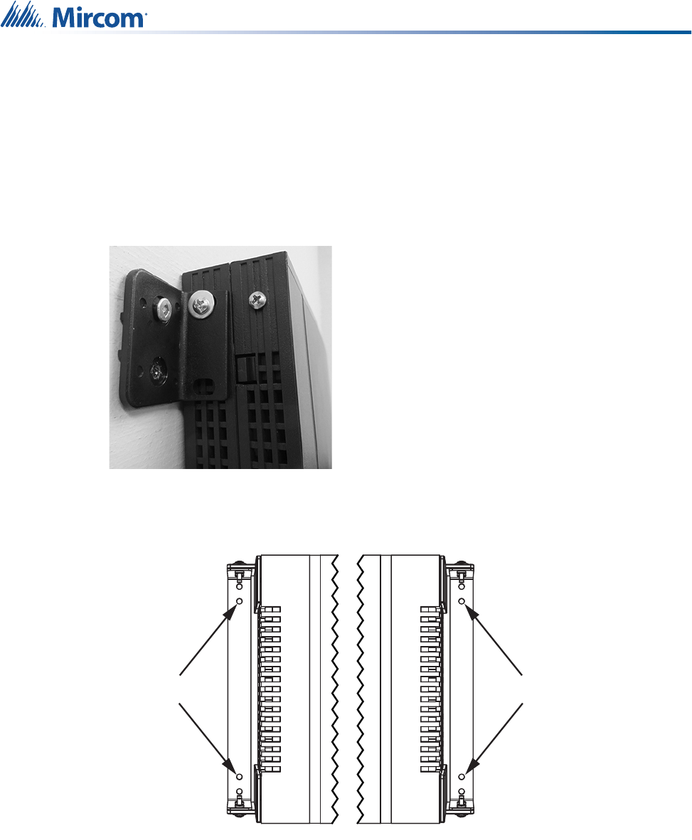
2.5 Mounting
Both models ship with 2 mounting brackets. Use the brackets to mount the Coordinator Bundle
to a wall or wooden shelf. Mount the Coordinator Bundle in a clear open area.
Figure 8 NC-2100K (1U model) mounted to a wall
Figure 9 NC-2100K (2U model) mounting holes
2.6 Maintenance and Service
Mircom recommends that each Coordinator Bundle be tested on a weekly basis.
When performing service on a Coordinator Bundle, disconnect the device from the Central
server, disconnect the USB cable, and then disconnect it from power before accessing any
serviceable areas.
Mounting holes Mounting holes

16
3.0 Installing the NC-2000 Patient Unit
The NC-2000 Patient Unit is the backbone of the MiCare Nurse Call and
Emergency System wireless network. This chapter provides an overview of
the Patient Unit and installation.
In this chapter you will find the following:
•Overview
•Telephone Connections
•Inputs
•Dome Lights and Generic Outputs
•Paging Input
•Bed Cords
•Secondary Ultrasound Transmitter
•Power
•Mounting the Patient Unit
•LED Status Indicators
•Maintenance and Service
•Restarting the Patient Unit
17
Installing the NC-2000 Patient Unit
3.1 Overview
The NC-2000 Patient Unit is the backbone of the wireless mesh network that connects all the
Nurse Call and Emergency System devices together. End devices (for example, the Pull
Station and the ZF3) send messages to the Patient Unit, and the Patient Unit then passes
these messages to the NC-2100K Coordinator Bundle and the Nurse Call and Emergency
System Central server for processing.
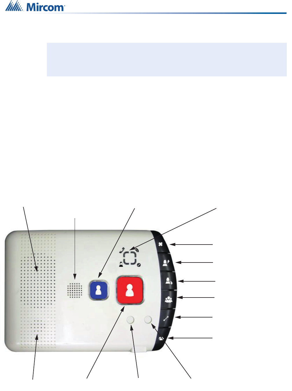
Figure 10 shows the front of the Patient Unit and its features, which include:
• Four LED status indicators
• Speaker and microphone for two-way voice communication with an attendant
• Ultrasound transmitter to locate portable MiCare end devices in the room
• Eight buttons (Code Blue, Emergency, Cancel, Nurse In, Nurse Out, Staff Assist,
Maintenance, and Custom Programming)
• Two bed cord jacks
Figure 10 The front of the NC-2000 Patient Unit
The back of the Patient Unit has terminals for the following connections:
Install in accordance with the Canadian Electrical Code or the National Electrical
Code, and comply with all local regulations. Final acceptance subject to the Local
Authority Having Jurisdiction (AHJ).
!
Cancel
Nurse In
Nurse Out
Staff Assist
Maintenance
Custom Programming
Emergency
Code Blue
Bed Cord 2 Bed Cord 1
LED Status Indicators
Microphone
Speaker Ultrasound
Transmitter
18
Installing the NC-2000 Patient Unit
• Telephone Connections
• Inputs
• Dome Lights and Generic Outputs
• Paging Input
• Secondary Ultrasound Transmitter
•Power
These connections are covered in sections 3.2 to 3.8.
Section 3.9, Mounting the Patient Unit, describes how to mount the Patient Unit to a standard
3 gang PVC box. Note that the Patient Unit is not intended to be used in an Oxygen-Enriched
Environment.
Section 3.11, Maintenance and Service, covers the recommended maintenance and service
procedures for the Patient Unit.
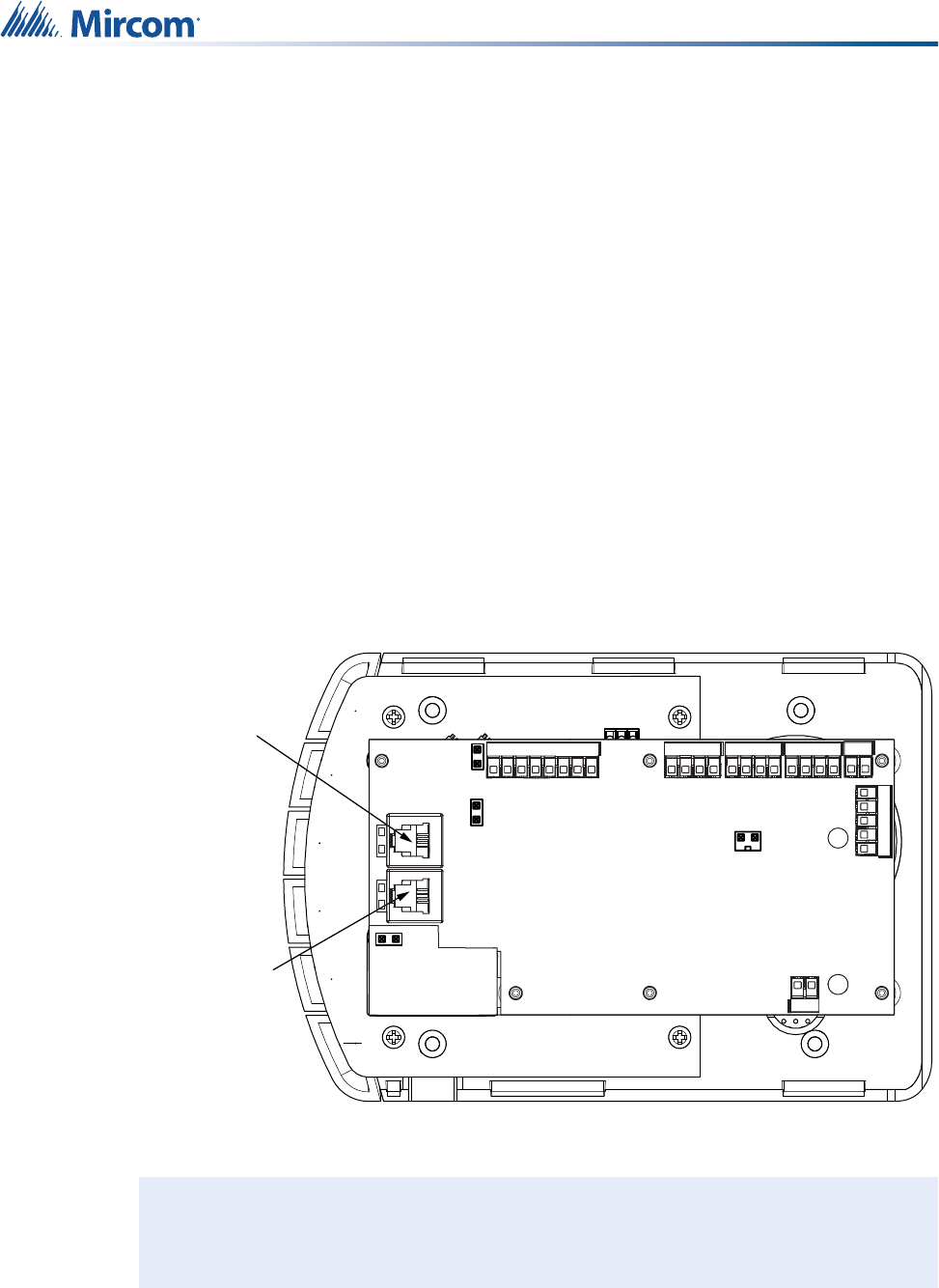
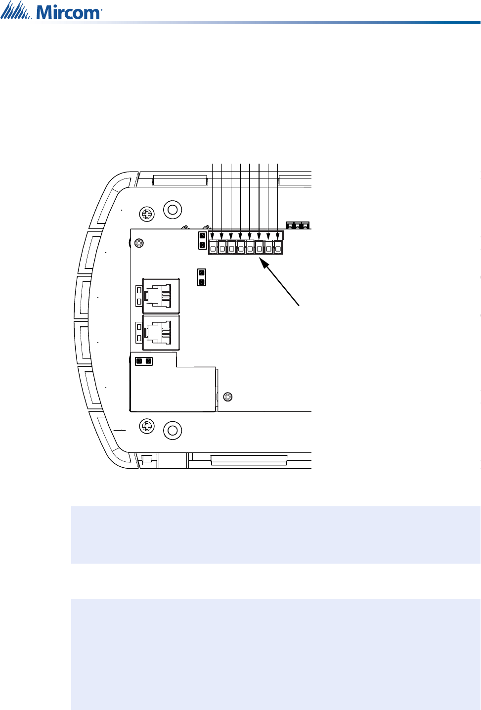
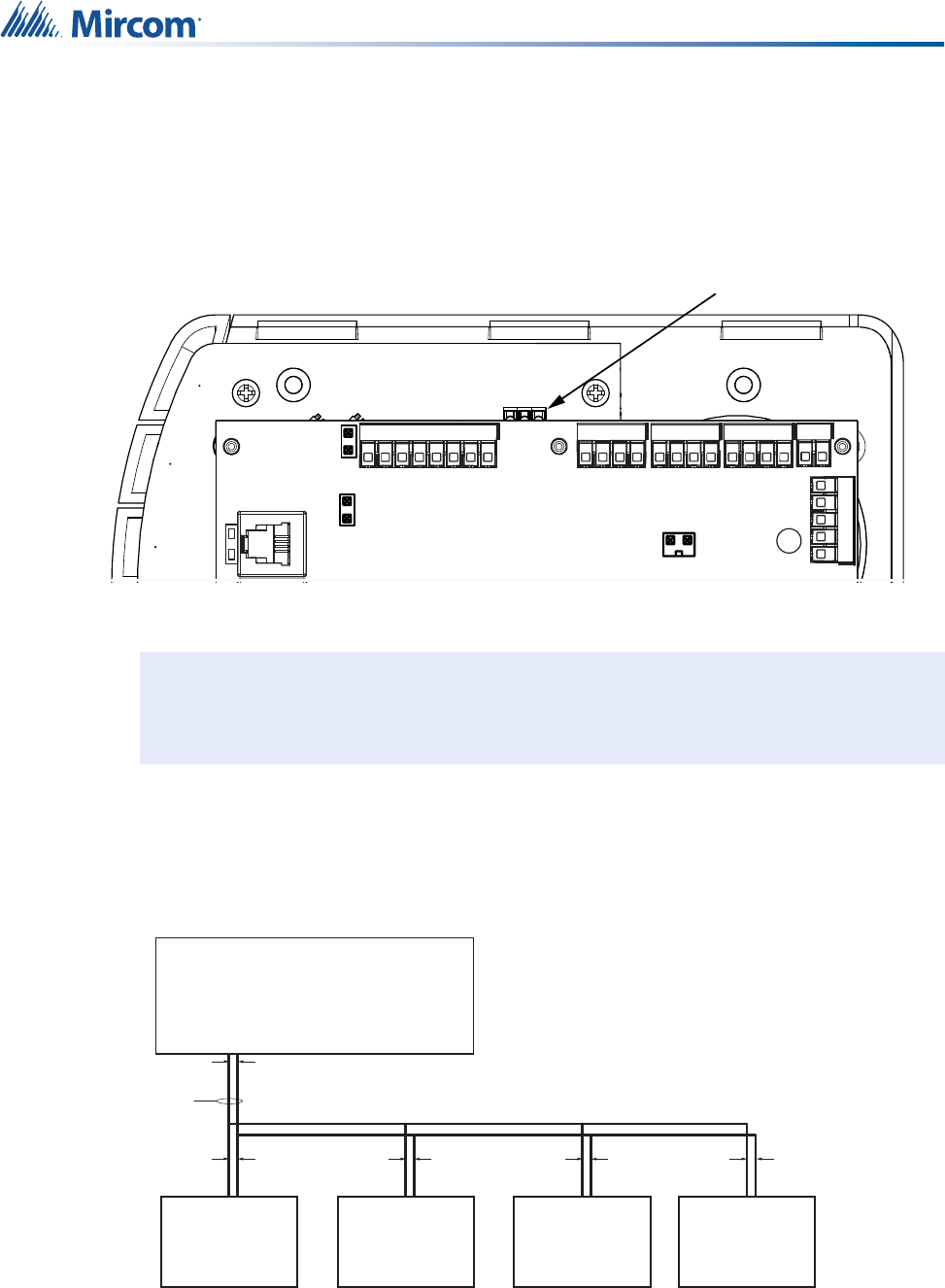
3.2 Telephone Connections
The back of the Patient Unit has two telephone terminals, CN1 and CN2 (see Figure 11). CN1
is the telephone line in, and CN2 goes to the extension(s) in the room.
Figure 11 Telephone interface terminals CN1 and CN2
There are four pins in each terminal. The two center pins carry the TIP and RING signals for
the first extension, and the two outer pins carry the TIP and RING signals for the second
extension (if present). Terminals CN1 and CN2 are connected through relays. The relays
Note: Do not overtighten the screw terminals.
CN1: Telephone
Line IN
CN2: Connect to
extension(s)
J3
J4
COM
LOW
HIGH
CN16
CN13
CN6
CN2
CN1
CN2
CN8
i

19
Installing the NC-2000 Patient Unit
break the connection to the extension(s) to allow the Patient Unit to place a call even when an
extension is in use.
CN1 and CN2 take RJ-11 connectors. Table 2 shows the pin connections to make for an RJ-11
connector. Note that the outermost pins (1 and 6) on the RJ-11 are not used.
Note: To enable two-way voice communication, see the Globals chapter in LT-2075, the
MiCare Nurse Call and Emergency System Administrator’s Guide.
Table 2 Pin assignments for an RJ-11 connector
Pin Function
1Not connected
2TIP for extension 2
3TIP for extension 1
4RING for extension 1
5RING for extension 2
6No connect
i
20
Installing the NC-2000 Patient Unit
3.3 Inputs
Terminal CN6 has four wet contact inputs for call points (with ground returns) on a screw-type
terminal block. Inputs should be grounded to their respective ground return through a contact
to indicate activity. See Figure 12 for the locations of the four inputs and their ground returns.
Figure 12 Input connections on CN6
Note: Do not overtighten the screw terminals.
Notes: The following points regarding the inputs apply:
• Inputs connected to CN6 should be of the normally open type.
• For supervision, connect a 10K ohm resistor across the input.
• Circuits connected to the inputs must be limited to a voltage of less
than 30V and power less than 100VA in order to comply with
UL 1069 and UL 2560.
COM
LOW
HIGH
INPUT 1
INPUT 2
INPUT 3
INPUT 4
GND 3
GND 1
GND 2
GND 4
CN6
J3
J4
COM
LOW
HIGH
CN16
CN13
CN6
CN2
CN1
CN2
i
i
21
Installing the NC-2000 Patient Unit
3.4 Dome Lights and Generic Outputs
The Patient Unit supports the following connections for outputs:
•Dome lights: there are 4 powered outputs for an external 4-light dome light - see Figure
13. Mircom supplies the NC-4LED Corridor Light. Other dome lights are available
through third party manufacturers.
•Generic outputs: these are 4 generic dry-contact outputs to activate either normally
open or normally closed external devices - see Figure 15
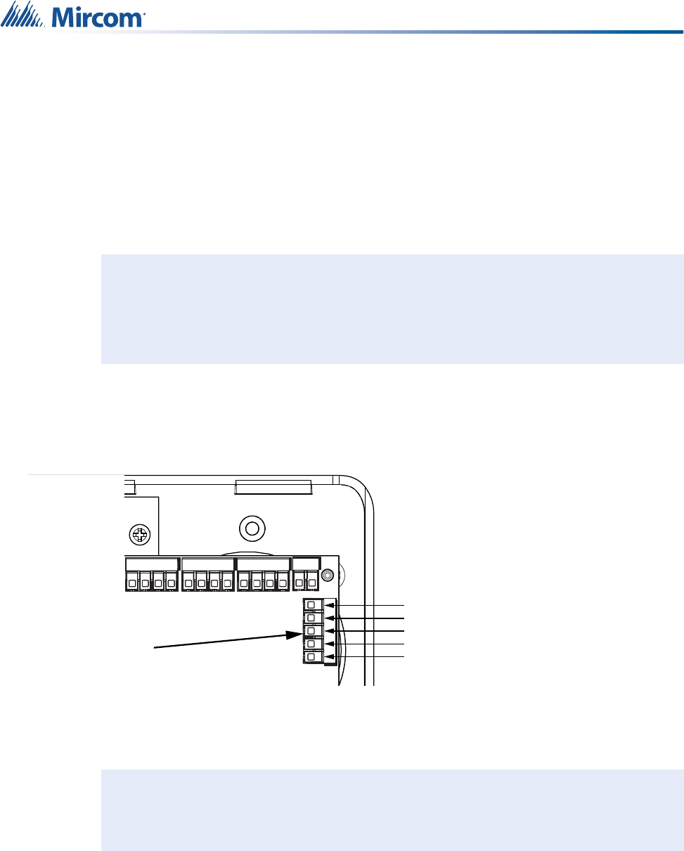
3.4.1 Connecting Third Party Dome Lights
Dome lights connect to terminal CN16, a 5-position screw down block. There are 4 live outputs
and a common return for a 5-wire 4-light interface (see Figure 13). These relays are limited to
500 mA maximum each.
Figure 13 Dome light connections on terminal CN16
Wire dome lights by connecting each light to its active output and to the common return.
Note: The outputs for the dome lights on CN16 are tied to the generic outputs on CN13.
If, for example, you activate output 1, output 1 on CN13 and output 1 on CN16
both become active. For information on how to activate outputs, see the Rules
chapter in LT-2075, the MiCare Nurse Call and Emergency System
Administrator’s Guide.
Note: Do not overtighten the screw terminals.
i
COM
LOW
HIGH
Dome Light 4
Dome Light 3
Dome Light 2
Dome Light 1
Common return for all dome lights
CN16
CN13
CN6
CN2
CN16
i

22
Installing the NC-2000 Patient Unit
3.4.2 Connecting NC-4LED
The NC-4LED corridor light has six wires.
Note: Third part dome light manufacturers may use low current LEDs or higher current
incandescent lamps. LED dome lights typically range from 5 to 50 mA each, and
incandescent lamps typically range from 50 to 250 mA each. The dome light
relays (CN16) supply up to 500 mA each. Ensure that the dome lights do not
exceed 500 mA each (total of 2.0 A for 4 dome lights).
When calculating the power supply requirements for the Patient Unit, you must
include the power requirements for the dome lights.
For example, with four 24 V incandescent light bulbs at 250 mA each, the
following input currents are drawn by the Patient Unit (at 24 VDC output):
• Patient Unit maximum current: 25 mA
• 4 dome lights on: 1000 mA
In this example, use a power supply rated at 1.25 A or more.
See section 3.8, Power, on page 27 for more information on power connections.
Table 3 NC-4LED
Color Label Connect to
Red R Output 4 on CN16
Green G Output 3 on CN16
Amber A Output 2 on CN16
White W Output 1 on CN16
Brown V/G Common return of dome lights
Blue L.F. Not Connected
i
23
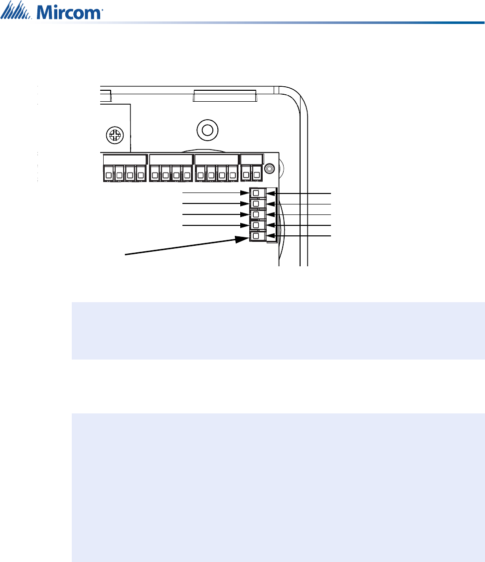
Installing the NC-2000 Patient Unit
1. Connect the first 5 wires to terminal CN16, a 5-position screw down block. There are 4
live outputs and a common return for the brown wire (see Figure 14).
Figure 14 NC-4LED connections on terminal CN16
NC-4LED electrical ratings:
• 24 VDC @ 40 mA per LED (total of 160 mA for all 4 LEDs)
Note: Do not overtighten the screw terminals.
Note: When calculating the power requirements for the Patient Unit, you must include
the power requirements for the dome lights.
For example, with NC-4LED, the following input currents are drawn by the
Patient Unit (at 24 VDC output):
• Patient Unit maximum current: 25 mA
• NC-4LED: 160 mA
In this example, use a power supply rated at 200 mA or more.
Note: See section 3.8, Power, on page 27 for more information on power connections.
COM
LOW
HIGH
CN16
CN13
CN6
CN2
CN16
Output 1
Output 2
Output 3
Output 4 R
G
A
W
V/G
i
i
24
Installing the NC-2000 Patient Unit
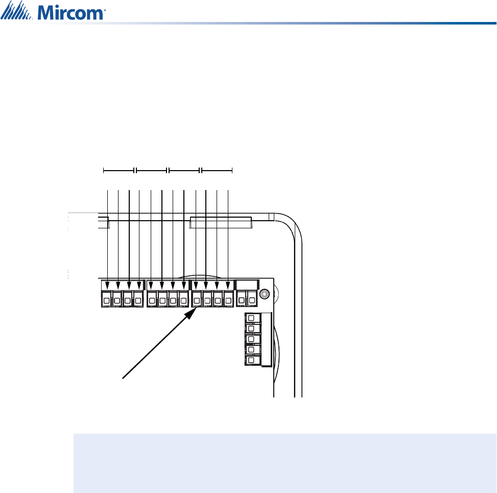
3.4.3 Connecting Generic Outputs
There are four generic dry-contact outputs located on terminal CN13. These outputs can be
used to operate a normally open (NO) or normally closed (NC) switch, such as a magnetic
door lock. Each output has connections for normally open (NO), normally closed (NC), and
common (C) contacts (see Figure 15).
Figure 15 Generic output connections on terminal CN13.
The relay contacts for each output are fused with 900mA PTC protection devices to prevent
damage from excessive current.
Note: Do not overtighten the screw terminals.
COM
LOW
CN16
CN13
CN13
NC
NO
C
NC
NO
C
NC
C
NO
NC
C
NO
Outputs
4321
i
25
Installing the NC-2000 Patient Unit
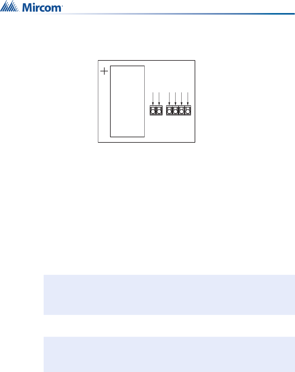
3.5 Paging Input
The paging input terminal, CN2, is located on the keypad circuit board below the main circuit
board (see Figure 16).
Figure 16 External paging input terminal CN2
When connecting to an external paging amplifier, follow these guidelines:
• Use a dedicated pair of 22AWG wires from each Patient Unit to the paging amplifier.
• If your paging amplifier outputs 25 V, connect the outputs on the paging amplifier to the
LOW and COM inputs on CN2.
Figure 17 Paging amplifier - 25 V output
Note: Do not overtighten the screw terminals.
External Paging Input
CN2
J3
J4
COM
LOW
HIGH
CN16
CN13
CN6
CN2
CN1
CN8
i
Paging Amplifier
25V output
22AWG
COMLOW COM
C
25V
NC-2000
CN2
COMLOW
NC-2000
CN2
COMLOW
NC-2000
CN2
LOW
NC-2000
CN2
26
Installing the NC-2000 Patient Unit
• If your paging amplifier outputs 75 V, connect the outputs on the paging amplifier to the
HIGH and COM inputs on CN2.
Figure 18 Paging amplifier - 75 V output
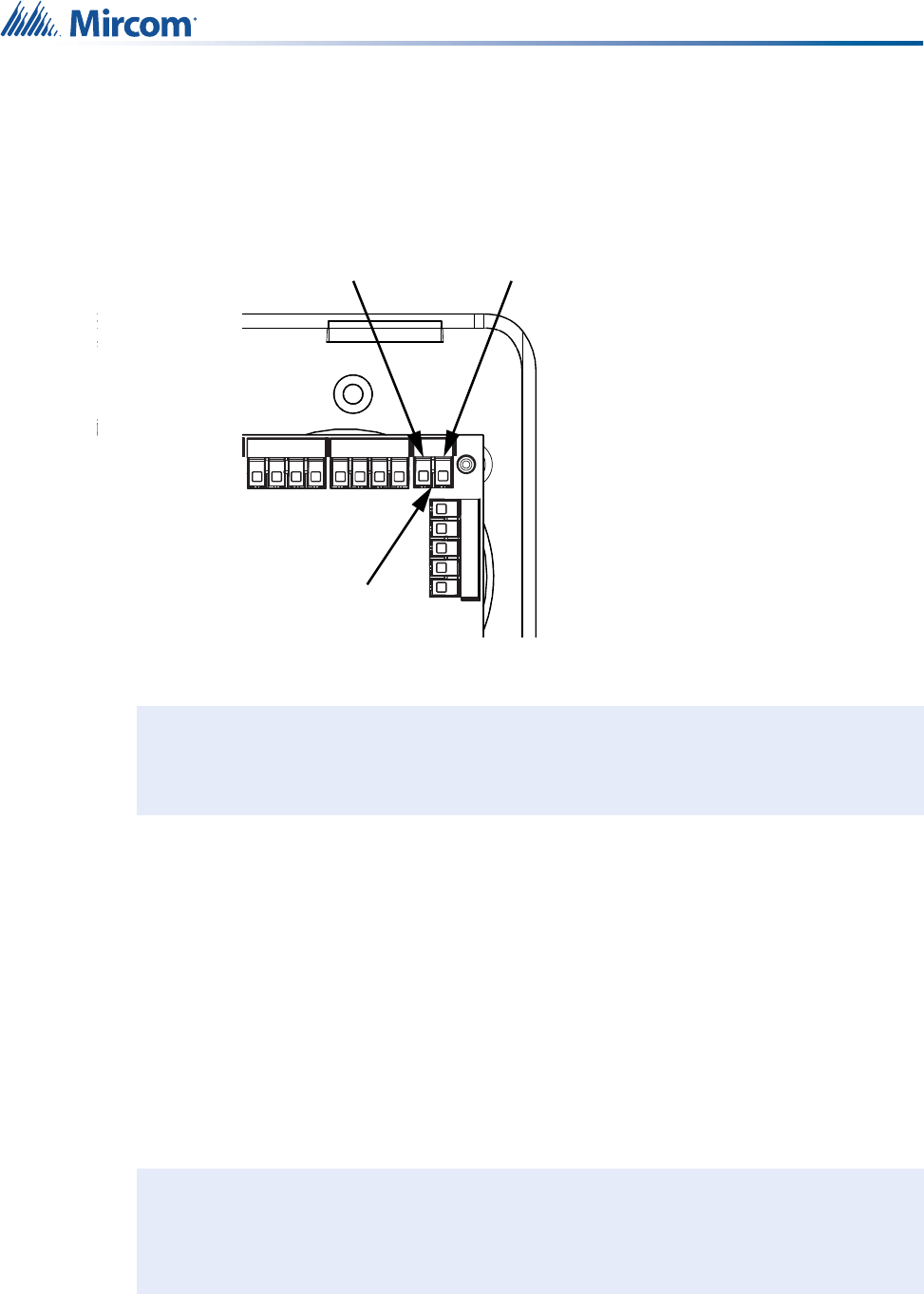
3.6 Bed Cords
The Patient Unit has two 0.25 inch jacks for bed cords. Each jack is supervised.
• If two bed cords are being used, close the jumper shown in Figure 19.
• If only one bed cord is being used, insert a 0.25 inch dummy plug in the unused jack and
close the jumper shown in Figure 19.
• If no bed cords are being used, open the jumper shown in Figure 19.
Figure 19 Bed cord input terminal CN3
Paging Amplifier
75V output
22AWG
COMHIGH COM
C
75V
NC-2000
CN2
COMHIGH
NC-2000
CN2
COMHIGH
NC-2000
CN2
HIGH
NC-2000
CN2
Jumper
27
Installing the NC-2000 Patient Unit
3.7 Secondary Ultrasound Transmitter
Terminal CN14 is used to connect the Patient Unit to a secondary ultrasound transmitter (see
Figure 20). The second driver transmitter will have the same ID as the Patient Unit and it can
be placed in a separate location from the Patient Unit.
Figure 20 External ultrasonic emitter terminal CN14
3.8 Power
The Patient Unit requires 24VDC for power. The maximum input current for the Patient Unit is
2.025 A, of which the dome lights are the major contributor. When you are calculating the
power supply current requirements for the Patient Unit, you must add the following together:
1. Patient Unit maximum current: 25 mA
2. The maximum current for your dome lights (check with dome light manufacturer). The
dome light relays are limited to 2.0 A maximum (4 relays x 500 mA per relay).
The sum of 1 and 2 must not exceed 2.025 A and must be less than the maximum current
output of your power supply.
Note: Do not overtighten the screw terminals.
Notes: When using the RB-MD-990 power supply to power more than one device,
calculate the total amount of current required for all devices connected—Patient
Units along with their dome lights—so as not to exceed the power output of the
power supply or the power ratings for any connectors.
COM
LOW
CN14
Ultrasonic Drive +
Ultrasonic Drive -
i
i
28
Installing the NC-2000 Patient Unit
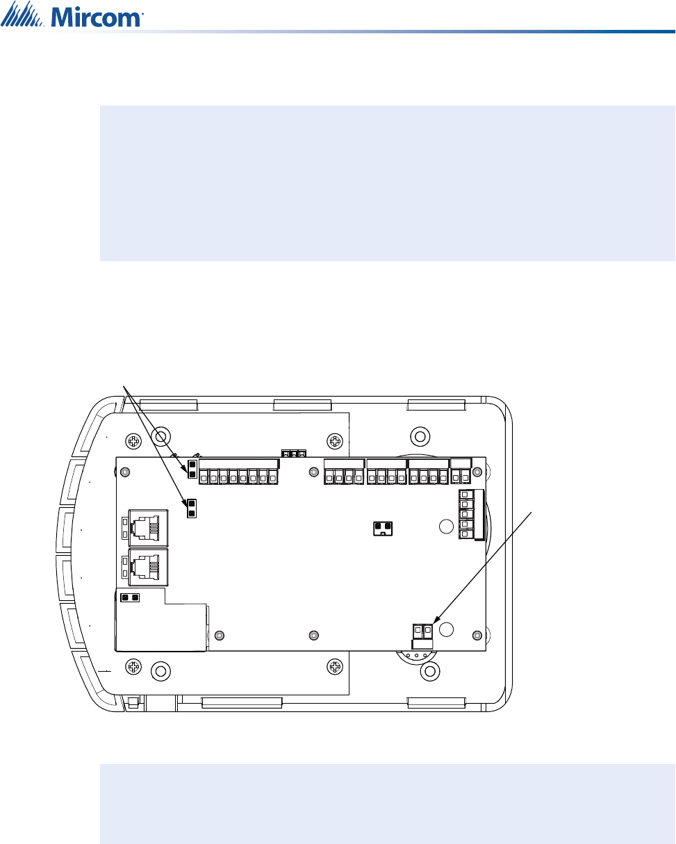
3.8.1 Connecting Power
The power connection terminal is CN11, a screw-type terminal block (see Figure 21).
Figure 21 Power terminal CN11 and jumpers J3 and J4
To power the Patient Unit:
1. Attach the wires from your power supply to CN11.
The inputs are polarity independent. There should be no exposed wire present. The
screws must be set securely enough so that the wires cannot come loose.
2. If there are jumpers on J3 or J4, remove them.
Attention: In order to comply with UL 2560, you must do the following:
• Connect all Class 2 power supplies for the Patient Units to a
power-limited uninterruptible power source (UPS) for back up
power.
• Refer to Appendix 2: UL 2560 Requirements for UPS
(Uninterruptible Power Supply) for more information about the
UPS.
Note: Do not overtighten the screw terminals.
!
J3 and J4
Open
Power Terminal
CN11 (24VDC)
J3
J4
COM
LOW
HIGH
CN16
CN13
CN6
CN2
CN1
CN2
CN8
i
29
Installing the NC-2000 Patient Unit
3.8.2 Optional Battery
A rechargeable nickel-cadmium battery (part number NC-PBAT) can be purchased from
Mircom to provide standalone power for the Patient Unit. The battery connects to the battery
terminal CN8 (see Figure 22). To secure the battery, loop a cable tie through the two holes in
the circuit board and then tighten it around the battery.
Figure 22 Battery terminal CN8
3.9 Mounting the Patient Unit
The Patient Unit mounts on the supplied mounting plate, which attaches to a standard 3 gang
PVC box. Note that the Patient Unit is not intended to be used in an Oxygen-Enriched
Environment.
Note: Do not overtighten the screw terminals.
Attention: The battery alone does not meet the requirements for UL 2560 because
it does not power the dome lights. In order to comply with these
standards, connect the Class 2 power source for the Patient Unit to a
power-limited uninterruptible power source (UPS).
Note: Prior to mounting the Patient Unit, record its MAC address and location (building,
wing, floor, and room). This information is needed to add the Patient Unit to the
MiCare Central server. Appendix 5: Device Installation Table on page 59 has an
example device installation table that you can use to record this information.
J3
J4
COM
LOW
HIGH
CN16
CN13
CN6
CN2
CN1
CN2
CN8
Battery Terminal
CN8
Holes for
cable tie
Battery - Battery +
i
!
i
30
Installing the NC-2000 Patient Unit
To mount the Patient Unit:
1. Attach the mounting plate to the 3 gang PVC box using four screws (see Figure 23).
Figure 23 Patient Unit mounting plate
2. Attach the Patient Unit to the mounting plate.
3.10 LED Status Indicators
Table 4 Patient Unit LED Status Indicators
LED Function
Top Left
Off: The phone line is not enabled.
Red blinking: The phone line is enabled but no phone is connected.
Steady green: A phone is connected.
Top Right
Red blinking: The Code Blue, Emergency, Staff Assist, Maintenance
or Custom Programming buttons are pressed.
Bottom Left
Green Blinking: The Patient Unit has not joined the network.
Steady green: The Nurse In button is pressed.
Red blinking for 10 seconds: The Nurse Out button is pressed.
Bottom Right
Steady red: There is a fault, for instance when the unit loses its
custom settings.
Mounting Holes

31
Installing the NC-2000 Patient Unit
3.11 Maintenance and Service
Mircom recommends that each Patient Unit be tested on a weekly basis.
When performing service on a Patient Unit, disconnect power and all connections (inputs and
outputs) going to the unit before accessing any serviceable areas.
3.12 Restarting the Patient Unit
To restart the Patient Unit
• Press the Cancel and Nurse Out buttons at the same time.
To reset the Patient Unit to factory default settings
• Press the Cancel and Staff Assist buttons at the same time.
For information on the default settings, see LT-2075 MiCare Administrator’s Guide.

32
4.0 Installing the NC-210/NC-211
Beacon
The MiCare Beacon provides a fast and easy way to extend the Nurse Call
and Emergency System. This chapter provides an overview of the Beacon
and how to install it.
In this chapter you will find the following:
•Overview
•NC-210
•NC-211
•Installing the Beacon
•Maintenance and Service
33
Installing the NC-210/NC-211 Beacon
4.1 Overview
The MiCare Beacon has all of the message routing functionality of the NC-2000 Patient Unit.
That is, the Beacon communicates with end devices on the network and passes messages
from the end devices to the Nurse Call and Emergency System Central server for processing.
The Beacon can be used in conjunction with a Patient Unit (for example, to extend the Patient
Unit’s range in a large room) or as a stand alone router.
There are two models of the Beacon.
• NC-210
•NC-211
4.2 NC-210
Figure 24 shows the front of the NC-210 Beacon and its features, which include:
• Security screw
• LED status indicator
• Ultrasound transmitter
Figure 24 The front of the NC-210 Beacon
4.2.1 LED Status Indicator on NC-210
Green blinking: The Beacon has not joined a network.
Steady green: The Beacon has joined a network.
Install in accordance with the Canadian Electrical Code or the National Electrical
Code, and comply with all local regulations. Final acceptance subject to the Local
Authority Having Jurisdiction (AHJ).
!
Ultrasound Transmitter
LED Status Indicator
Security Screw
34
Installing the NC-210/NC-211 Beacon
4.3 NC-211
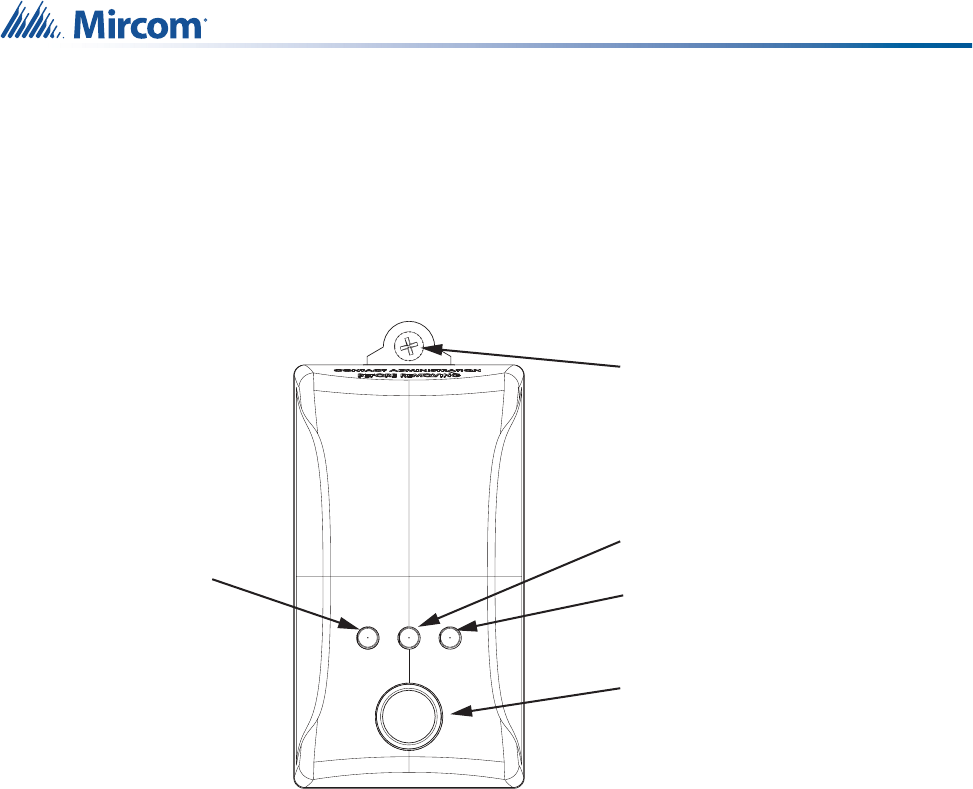
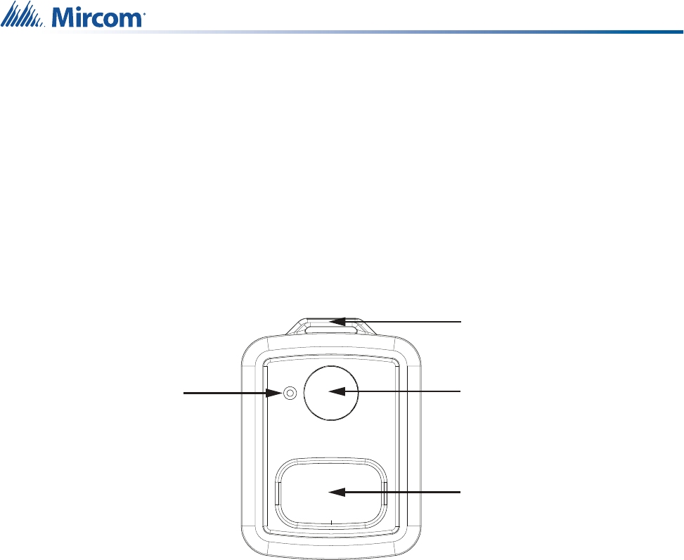
Figure 25 shows the front of the NC-211 Beacon and its features, which include:
• Security screw
• LED status indicators
• Ultrasound transmitter
Figure 25 The front of the NC-211 Beacon
4.3.1 LED Status Indicators on NC-211
Steady yellow: The Beacon is powered by AC.
Green blinking: The Beacon has not joined a network.
Steady green: The Beacon has joined a network.
Steady blue: The Beacon’s battery is charging.
Blue blinking: The battery has stopped charging because of a problem. See section
“Troubleshooting the NC-211 Battery” on page 36.
Blue off: The battery is charged.
When the beacon is in normal operation, then the yellow and green LEDs are on steady and
the blue LED is off.
Ultrasound Transmitter
Green LED
Security Screw
Blue LED
Yellow LED
35
Installing the NC-210/NC-211 Beacon
4.3.2 NC-211 Battery
The NC-211 Beacon contains a battery for supplementary operation. It is not a secondary
source of power.
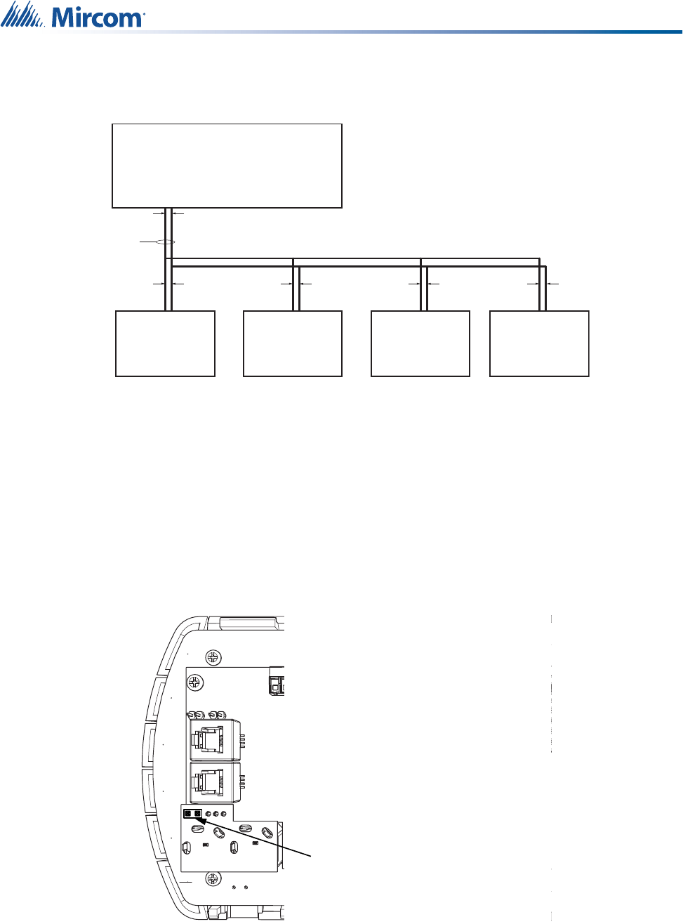
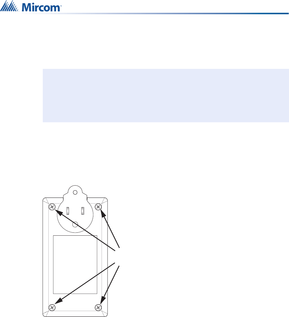
4.3.3 Before Installing NC-211 for the First Time
Before you install NC-211, you must activate the battery.
To activate the NC-211 battery:
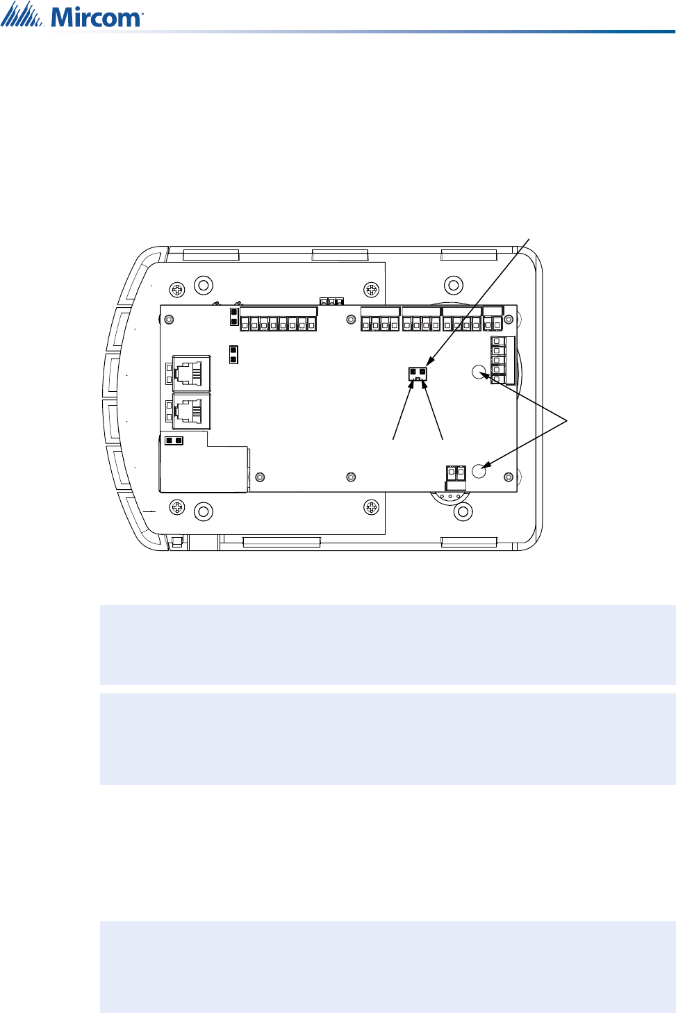
1. Open the enclosure by removing the 4 screws and removing the back cover.
Figure 26 NC-211 (back view)
Attention: In order to comply with UL 2560, connect all power supplies for the
Beacons to a power-limited uninterruptible power source (UPS) for
back up power. The UPS will report AC loss troubles.
Refer to Appendix 2: UL 2560 Requirements for UPS (Uninterruptible
Power Supply) for more information about the UPS.
!
Screws (x4)
36
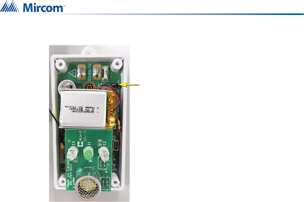
Installing the NC-210/NC-211 Beacon
2. Close jumper JW1.
Figure 27 JW1 on NC-211
3. Attach the back cover and secure it with the 4 screws.
Troubleshooting the NC-211 Battery
If the blue (rightmost) LED blinks, it means that the battery has stopped charging.
• Unplug the beacon, wait for 1 minute, and then plug the beacon back into the wall.
• If the blue LED continues to blink, then contact Mircom customer service.
4.3.4 Audible Low Battery Indication
The NC-211 beeps when there is no AC power and the battery is low. When AC power is
restored, the battery starts charging and the beeping stops.
Close
JW1

37
Installing the NC-210/NC-211 Beacon
4.4 Installing the Beacon
Both models of Beacon plug into a standard three prong 120 VAC electrical outlet. Refer to
Appendix 1: Specifications for the Beacons’ electrical ratings. It is recommended that some
form of back up power be used. Note that the Beacon is not intended to be used in an Oxygen-
Enriched Environment.
To install the Beacon:
• Plug the Beacon into a standard 120 VAC three-pronged outlet.
4.5 Maintenance and Service
Mircom recommends that each Beacon be tested on a weekly basis.
When performing service on a Beacon, disconnect it from power before accessing any
serviceable areas.
Attention: In order to comply with UL 2560, perform all of the following tasks:
• Connect all power supplies for the Beacons to a power-limited
uninterruptible power source (UPS) for back up power.
• Refer to Appendix 2: UL 2560 Requirements for UPS
(Uninterruptible Power Supply) for more information about the
UPS.
Note: Prior to mounting the Beacon, record its MAC address and location (building,
wing, floor, and room). This information is needed to add the Beacon to the
MiCare Central server. Appendix 5: Device Installation Table on page 59 has an
example device installation table that you can use to record this information.
Attention: If your installation must comply with UL 1069 or CSA No. 205, note the
following:
• In order to comply with UL 1069, do not install the Beacon in a
patient care vicinity area. Secure the Beacon to the wall with
the security screw. The receptacle must be standard (with a
screw in the middle), and not a designer or decorative
receptacle. Plug the Beacon into the bottom outlet, and secure
it with the security screw through the hole in the middle of the
receptacle.
• In order to comply with CSA No. 205, do not install the
security screw with the Beacon.
!
i
!

38
5.0 Installing the NC-103 Pull Station
The NC-103 Pull Station is a fully stand alone end device that communicates
with the routers (Patient Units and Beacons) in the Nurse Call and Emergency
System. This chapter provides an overview of the Pull Station and its
connections.
In this chapter you will find the following:
•Overview
•Input
•Power
•Mounting the Pull Station
•LED Status Indicator and Beeper
•Maintenance and Service
39
Installing the NC-103 Pull Station
5.1 Overview
The NC-103 Pull Station is an end device in the MiCare Nurse Call and Emergency System.
The Pull Station communicates wirelessly with the routers (Patient Units or Beacons) in the
Nurse Call and Emergency System.
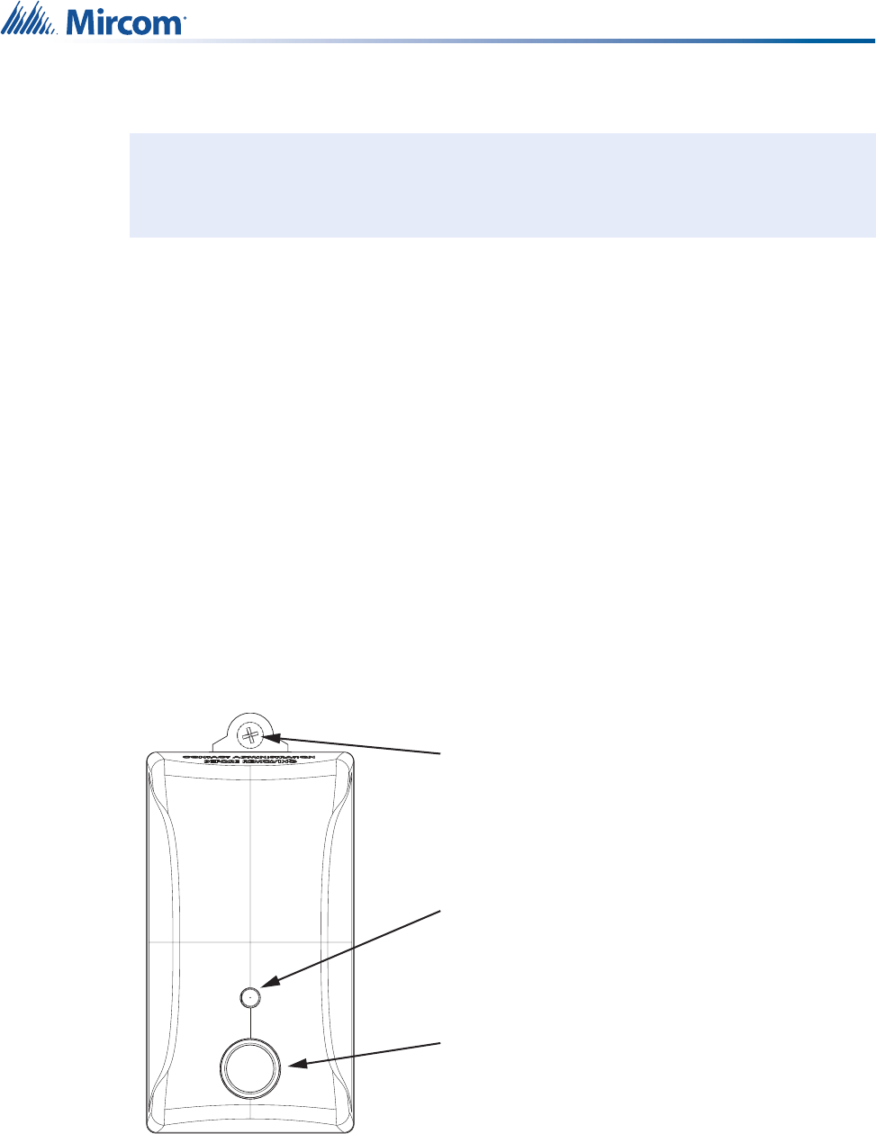
Figure 28 shows the front of the Pull Station and its features, which include:
• Emergency button
• LED status indicator
• Staff Assist button
• Cancel button
• Pull cord (emergency)
Figure 28 The front of the NC-103 Pull Station
The Pull Station has terminals for the following connections:
• Input
•Power
These connections are covered in sections 5.2 and 5.3.
Install in accordance with the Canadian Electrical Code or the National Electrical
Code, and comply with all local regulations. Final acceptance subject to the Local
Authority Having Jurisdiction (AHJ).
!
Emergency
LED Status Indicator
Staff Assist
Cancel
Pull Cord (Emergency)

40
Installing the NC-103 Pull Station
Section 5.4, Mounting the Pull Station, describes how to mount the Pull Station to a single
gang PVC box. Note that the Pull Station is not intended to be used in an Oxygen-Enriched
Environment.
Section 5.6, Maintenance and Service, covers the recommended maintenance and service
procedures for the Pull Station.
5.2 Input
The Pull Station can monitor the state of a normally open input. When the input becomes
active, the Pull Station reports this to Nurse Call and Emergency System Central server.
Examples of inputs include a door contact or a flood detector.
The operating specifications for the input on the Pull Station are:
• Wet contact pair, supplied voltage is max 3.6 V
• Nominal current of 1.4 mA (external loop closed)
• Maximum current 5 mA
To connect an input, attach the positive and negative wires from the input to the positive (+)
and negative (-) terminals on TS1 (located on the back of the Pull Station).
5.3 Power
To power the Pull Station, insert two standard AA batteries in the battery terminals located on
the back of the Pull Station.
5.4 Mounting the Pull Station
The Pull Station mounts on the supplied mounting plate, which attaches to a standard single
gang PVC box. Note that the Pull Station is not intended to be used in an Oxygen-Enriched
Environment.
Note: Prior to mounting the Pull Station, record its MAC address and location (building,
wing, floor, and room). This information is needed to add the Pull Station to the
MiCare Central server. Appendix 5: Device Installation Table on page 59 has an
example device installation table that you can use to record this information.
Attention: The Pull Station is not to be installed in a shower stall or in an
equivalent location where water spray would be encountered.
i
!
41
Installing the NC-103 Pull Station
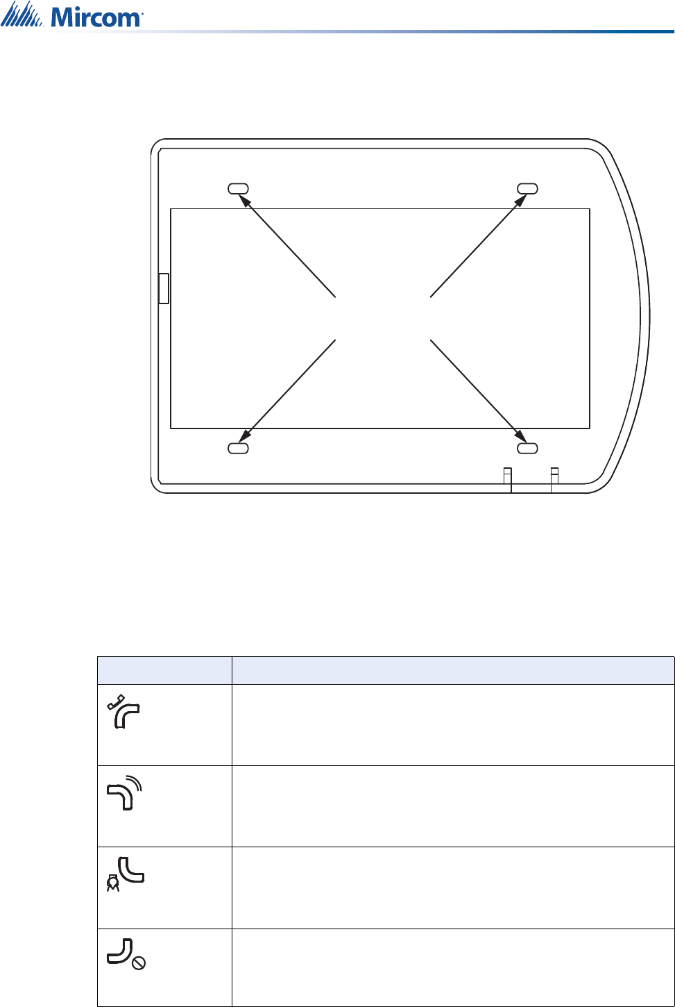
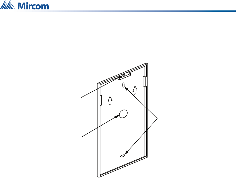
To mount the Pull Station:
1. If you are connecting an input to the Pull Station, run the wires for the input to the single
gang PVC box and then through the wiring hole on the mounting plate (see Figure 29).
2. Attach the mounting plate to the single gang PVC box using two screws (see Figure 29).
Figure 29 Pull Station mounting plate
3. Attach the Pull Station to the mounting plate.
4. Fasten the Pull Station to the mounting plate with a security bolt.
5.5 LED Status Indicator and Beeper
Medium green blinking: The Pull Station has not joined the network.
Slow green blinking: The Pull Station is sending a message.
One red blink: The current operation has failed.
The Pull Station uses two methods to send a message: it first sends a unicast message, and
then a broadcast message if the unicast message fails.
1. Unicast: the Pull Station waits to receive a confirmation from the Nurse Call and
Emergency System Central server that the message was received. The LED blinks red
once if the Pull Station does not receive a reply.
2. Broadcast: the Pull Station does not wait to receive a reply. This means that if the
broadcast message fails, the LED does not blink red. It simply blinks slow green during
the broadcast message, and then stops.
Beep: The Pull Station beeps when the Emergency button is pressed, when the Pull Station
has found a network, and when the Pull Station receives a reply.
Mounting
Holes
Wiring
Hole
Security
Bolt Hole

42
Installing the NC-103 Pull Station
5.6 Maintenance and Service
Mircom recommends that each Pull Station be tested on a weekly basis.
When performing service on a Pull Station, remove its batteries and then disconnect any input
connections before accessing any serviceable areas.

43
6.0 Installing the NC-220 ZF3
The NC-220 ZF3 is a fully stand alone end device that communicates with the
routers (Patient Units and Beacons) in the Nurse Call and Emergency
System. This chapter provides an overview of the ZF3 and its connections.
In this chapter you will find the following:
•Overview
•Inputs
•Power
•Mounting the ZF3
•Maintenance and Service
Note: The ZF3 is an auxiliary device for supplementary operation.
i

44
Installing the NC-220 ZF3
6.1 Overview
The NC-220 ZF3 is an end device in the MiCare Nurse Call and Emergency System. The ZF3
monitors up to 3 inputs (one for cancel button and two general purpose inputs) and
communicates wirelessly with the routers (Patient Units or Beacons) in the Nurse Call and
Emergency System.
The ZF3 has terminals for the following connections:
•3 Inputs
•Power
These connections are covered in sections 6.2 and 6.3.
Section 6.4, Mounting the ZF3, describes how to mount the ZF3. Note that the ZF3 is not
intended to be used in an Oxygen-Enriched Environment.
Section 6.5, Maintenance and Service, covers the recommended maintenance and service
procedures for the ZF3.
6.2 Inputs
The ZF3 can monitor the state of up to 3 normally open inputs (one cancel button and two
generic inputs). When an input becomes active, the ZF3 sends a notification to the 802.15.4
wireless network. This notification is then picked up by one of the routers in the Nurse Call and
Emergency System, which then sends it to the Central server for processing. Examples of
general purpose inputs that can be used with the ZF3 include auxiliary smoke detectors, door
contacts, cancel buttons, and motion sensors.
The operating specifications for the inputs on the ZF3 are:
• Wet contact pair, supplied voltage is max 3.6 V
• Nominal current of 1.4 mA (external loop closed) and an absolute maximum of 5 mA
Install in accordance with the Canadian Electrical Code or the National Electrical
Code, and comply with all local regulations. Final acceptance subject to the Local
Authority Having Jurisdiction (AHJ).
!
45
Installing the NC-220 ZF3
The input terminals for the ZF3 are TS1 (cancel button) and TS2 (2 generic inputs). They are
located on the ZF3 circuit board (see Figure 30). To connect an input, attach the positive and
negative wires from the input to the input and ground terminals on either TS1 or TS2.
Figure 30 Input terminals TS1 and TS2 on the NC-220 ZF3.
6.3 Power
To power the ZF3, insert a CR123A battery in the battery terminal, BT1, located on the ZF3
circuit board (see Figure 30).
6.4 Mounting the ZF3
The ZF3 mounts on a wall using four screws. After mounting the ZF3, attach the cover plate to
the unit.
Note that the ZF3 is not intended to be used in an Oxygen-Enriched Environment.
6.5 Maintenance and Service
Mircom recommends that each ZF3 be tested on a weekly basis.
When performing service on a ZF3, remove its battery and then disconnect any input
connections before accessing any serviceable areas.
Note: Prior to mounting the ZF3, record its MAC address and location (building, wing,
floor, and room). This information is needed to add the ZF3 to the MiCare Central
server. Appendix 5: Device Installation Table on page 59 has an example device
installation table that you can use to record this information.
Attention: The ZF3 is not to be installed in a shower stall or in an equivalent
location where water spray would be encountered.
TS1
TS2
BT1
CR123A
CANCEL
12
INPUT 1
INPUT 2
GND 1
GND 2
GND
INPUT
i
!

46
7.0 Installing The NC-500 Pendant
The MiCare NC-500 Pendant provides a fast and easy way to extend the
Nurse Call and Emergency System. This chapter provides an overview of the
Pendant and how to install it.
In this chapter you will find the following:
•Overview
•LED Status Indicator
•Using the Pendant
•Maintenance and Service
47
Installing The NC-500 Pendant
7.1 Overview
A patient wears the Pendant on a lanyard around the neck. If the patient needs assistance, he
or she presses the button, and the Pendant sends a message to the Nurse Call and
Emergency System Central server.
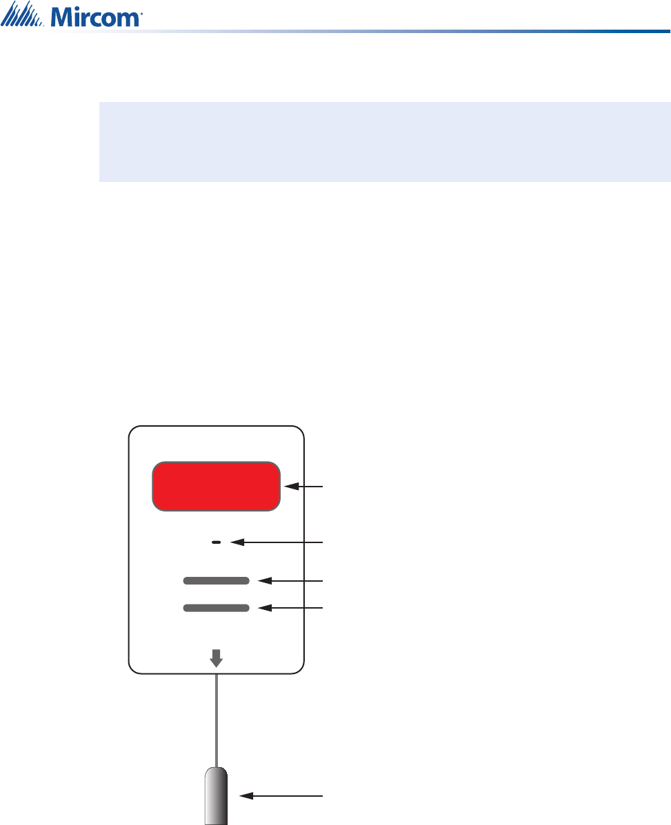
Figure 31 shows the front of the Pendant and its features, which include:
• Flexible outer cover
•Button
• Ultrasound receiver
• LED Indicator
Figure 31 The front of the NC-500 Pendant
7.2 LED Status Indicator
Fast green blinking: The Pendant is looking for an ultrasound device.
Medium green blinking: The Pendant is sending a message over the network.
Slow green blinking: The Pendant is waiting for a response to the message.
One red blink: The current operation has failed.
Fast green blinking followed by a red blink means that the Pendant failed to find an ultrasound
device. Even if the Pendant cannot find an ultrasound device, it will still send the message.
The Pendant uses two methods to send a message: it first sends a unicast message, and then
a broadcast message if the unicast message fails.
1. Unicast: the Pendant waits to receive a confirmation from the Nurse Call and Emergency
System Central server that the message was received. The LED blinks red once if the
Pendant does not receive a reply.
2. Broadcast: the Pendant does not wait to receive a reply. This means that if the broadcast
message fails, the LED does not blink red. It simply blinks slow green during the
broadcast message, and then stops.
Ultrasound
Receiver
LED Status
Indicator
Outer Cover
Button
48
Installing The NC-500 Pendant
7.3 Using the Pendant
To use the Pendant:
1. To call for assistance, press the button.
The LED blinks green to indicate that the Pendant is sending a message to the Nurse
Call and Emergency System Central server.
7.4 Canceling the Message from the Pendant
To cancel the message from the Pendant:
1. Wave a magnet over the Pendant.
The message disappears from the Nurse Call and Emergency System Central server.
7.5 Maintenance and Service
The Pendant uses one CR2450 battery. The estimated battery life is one year.
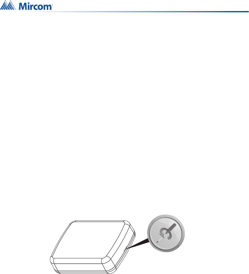
To replace the battery:
1. Remove the flexible outer cover.
2. Hold the pendant so that the button is facing down.
3. Insert a small screwdriver into the indentation between the bottom and top halves of the
case and turn to open the case.
Figure 32 Use a small screwdriver to open the case
49
Installing The NC-500 Pendant
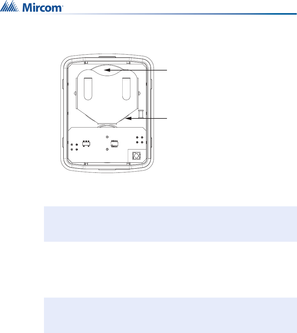
4. Carefully remove the circuit board from the case.
The battery holder is on top of the circuit board (Figure 33).
Figure 33 Pendant with bottom half of case removed
5. Insert a small screwdriver as shown in Figure 33 and push to gently slide out the battery.
6. Insert the replacement battery with the positive side facing up.
7. Place the circuit board in the top half of the case so that the ultrasound receiver fits in the
hole.
8. Snap the two halves of the case together.
9. Replace the flexible outer cover so that the pendant shows through the larger hole.
Mircom recommends that each Pendant be tested on a weekly basis.
When performing service on a Pendant, disconnect it from power before accessing any
serviceable areas
Attention: To prevent damage to the circuit boards, always hold them by the
edges.
Avoid touching the screwdriver to the circuit board components.
Note: There are holes on both sides of the flexible outer cover. Put the cover on the
pendant so that the front of the pendant shows through the larger hole.
Battery
Insert a small
screwdriver here
and and push to
gently slide out the
battery
!
i

50
8.0 Appendix 1: Specifications
8.1 NC-2000 Patient Unit
Standards: UL 1069, 2560, CSA 22.2 #205, FCC Part 15/Part 68, Class “B”, CS-03
Power Options: Input Power:
• Class 2 power supply 24 VDC, current range 200 mA to 2.5 A
(depending on dome lights - see dome light manufacturer for specific
current requirements)
Paging Wattage Requirements:
• Minimum 125 mW per unit
Wireless Characteristics: ZigBee:
• Frequency: 2.4 GHz
• Network type: 802.15.4 wireless mesh network
• Range: 23 m (75 ft) with line of sight
Ultrasonic transmitter:
• Frequency: 40 kHz
• Range: 9.1 m (30 ft)
Physical Characteristics: Faceplate: 221R Lexan
Impact Strength: 260 ft-lbs/in2
Actuator Material: Silicon Rubber
Color: Off White
Weight: 225g (8 oz)
Dimensions: 114 mm x 162 mm x 64 mm (4.5” H x 6.375” W x 2.5” D)
Mounting Centers: 3-9/32”
Standard 3-gang, 2.5” Deep PVC Back Box Required
Operating Temperature: 0º C to +50º C (32º F to 122º F)

51
Appendix 1: Specifications
8.2 NC-210 Beacon
Input/Output Operating
Specifications:
Inputs:
• Wet contact pair, supplied voltage is nominally 3.6 V (absolute maximum
5 V).
• Nominal current of 1.4 mA (external loop closed) and an absolute
maximum of 1.9 mA.
• Follow manufacturer’s specifications for any attached equipment or
wiring.
• End of Line Resistor: 10K ohms +/- 5% ½W
Outputs:
• General Purpose Relays: dry contact form C, 40 VDC @ 500 mA max.
per relay
• Dome Light Relays: dry contact form A, 24 VDC @ 500 mA max. per
relay
Install in accordance with the Canadian Electrical Code or the National
Electrical Code, and comply with all local regulations. Final acceptance
subject to the Local Authority Having Jurisdiction (AHJ).
Standards: UL 1069, 2560, CSA 22.2 #205, FCC Part 15, Class “B”, CS-03
Power Options: Input Power:
• 120 VAC @ 6.0 mA nominal
Wireless Characteristics: ZigBee:
• Frequency: 2.4 GHz
• Network type: 802.15.4 wireless mesh network
• Range: 23 m (75 ft) with line of sight
Ultrasonic transmitter:
• Frequency: 40 kHz
• Range: 9.1 m (30 ft)
Physical Characteristics: Enclosure: Acrylonitrile Butadiene Styrene
Impact Strength: 9.52 ft-lbs/in2
UL94V-0 Flame Rating
Color: White
Weight: 142 g (5 oz)
Dimensions: 104 mm x 56 mm x 32 mm (4.11” H x 2.23” W x 1.25” D)
Standard 3 pole grounded NEMA 5-15P
Operating Temperature: 0º C to +50º C (32º F to 122º F)

52
Appendix 1: Specifications
8.3 NC-211 Beacon
8.4 NC-103 Pull Station
Standards: UL 1069, 2560, CSA 22.2 #205, FCC Part 15, Class “B”, CS-03
Power Options: Input Power when connected to 120 VAC outlet:
• 120 VAC @ 9.0 mA nominal
Battery power:
• Type: Lithium-ion
• Nominal voltage: 3.7 V
• Capacity: 500 mAh
Wireless Characteristics: ZigBee:
• Frequency: 2.4 GHz
• Network type: 802.15.4 wireless mesh network
• Range: 23 m (75 ft) with line of sight
Ultrasonic transmitter:
• Frequency: 40 kHz
• Range: 9.1 m (30 ft)
Physical Characteristics: Enclosure: Acrylonitrile Butadiene Styrene
Impact Strength: 9.52 ft-lbs/in2
UL94V-0 Flame Rating
Color: White
Weight: 142 g (5 oz)
Dimensions: 104 mm x 56 mm x 32 mm (4.11” H x 2.23” W x 1.25” D)
Standard 3 pole grounded NEMA 5-15P
Operating Temperature: 0º C to +50º C (32º F to 122º F)
Standards: UL 1069, 2560, CSA 22.2 #205, FCC Part 15, Class “B”, CS-03
Power Options: Input Power:
• 2 x 1.5 V Alkaline AA Batteries
• Nominal Current: 10 μA
• Transmit Current: 35 mA
• Receive Current: 25 mA
• Transmit and Receive Frequency: 4 times a day

53
Appendix 1: Specifications
8.5 NC-220 ZF3 3 Input Transmitter (auxiliary device for
supplementary operation)
Wireless Characteristics: ZigBee:
• Frequency: 2.4 GHz
• Network type: 802.15.4 wireless mesh network
• Range: 23 m (75 ft) with line of sight
Physical Characteristics: Faceplate: 221R Lexan
Impact Strength: 260 ft-lbs/in2
Color: Off White
Weight: 113 g (4 oz)
Dimensions: 130 mm x 89 mm x 20 mm (5.1” H x 3.5” W x 0.8” D)
Standard 1-gang, 2.5” Shallow PVC Back Box Required
Operating Temperature: 0º C to +50º C (32º F to 122º F)
Input Operating
Specifications:
Wet contact pair, supplied voltage is max 3.6 V
Nominal current of 1.4 mA (external loop closed)
Maximum current 5 mA
Follow manufacturer’s specifications for any attached equipment or wiring.
Standards: CSA 22.2 #205, FCC Part 15, Class “B”, CS-03
Power Options: Input Power:
• 1 x 3 V CR123A Battery
• Capacity: 1550.0 mAh
• Nominal Current: 10 μA
• Transmit Current: 35 mA
• Receive Current: 25 mA
• Transmit and Receive Frequency: 4 times a day
Wireless Characteristics: ZigBee:
• Frequency: 2.4 GHz
• Network type: 802.15.4 wireless mesh network
• Range: 23 m (75 ft) with line of sight
Physical Characteristics: Enclosure: Plastic
Color: Black
Weight: 45 g (1.6 oz)
Dimensions of Enclosure: 111 mm x 60 mm x 40 mm (4.4” W x 2.4” D x
1.6” H)
Operating Temperature: 0º C to +50º C (32º F to 122º F)

54
Appendix 1: Specifications
8.6 NC-500 Pendant
8.7 NC-2100K Coordinator Bundle
Input Operating
Specifications:
Wet contact pair, supplied voltage is max 3.6 V
Nominal current of 1.4 mA (external loop closed) and an absolute maximum
of 5 mA
Follow manufacturer’s specifications for any attached equipment or wiring
Standards: UL 1069, 2560, CSA 22.2 #205, FCC Part 15, Class “B”, CS-03
Power Options: Input Power:
• 1 x 3 V CR2450 Battery
• Capacity: 540 mAh
• Nominal Current: 10 μA
• Transmit Current: 35 mA
• Receive Current: 25 mA
• Transmit and Receive Frequency: 4 times a day
Wireless Characteristics: ZigBee:
• Frequency: 2.4 GHz
• Network type: 802.15.4 wireless mesh network
• Range: 23 m (75 ft) with line of sight
Ultrasonic receiver:
• Frequency: 40 kHz
• Range: 9.1 m (30 ft)
Physical Characteristics: Enclosure: Germ-Wipeable Plastic
Color: White & Blue
Weight: 25g (0.9 oz)
Dimensions: 46 mm x 38 mm x 13 mm (1.8” H x 1.5” W x 0.5” D)
Operating Temperature: 0º C to +50º C (32º F to 122º F)
Standards: UL 1069, 2560, CSA 22.2 #205, FCC Part 15/Part 68, Class “B”, CS-03
Power Options: Input Power:
• 2 x Class 2 power supply 24 VDC, 25 mA maximum

55
Appendix 1: Specifications
8.8 RB-MD-990 Power Supply for UL 2560 Applications Only
Wireless Characteristics: ZigBee:
• Frequency: 2.4 GHz
• Network type: 802.15.4 wireless mesh network
• Range: 23 m (75 ft) with line of sight
Ultrasonic transmitter:
• Frequency: 40 kHz
• Range: 9.1 m (30 ft)
Physical Characteristics: Enclosure: Plastic
Color: Black
Weight: 1.18 kg (2.6 lb) (1U)
1.86 kg (4.1 lb) (2U)
Dimensions: 44 mm x 438 mm x 206 mm (1.75” H x 17.25” W x 8.1” D) (1U)
86 mm x 483 mm x 211 mm (3.4” H x 19” W x 8.3” D) (2U)
Operating Temperature: 0º C to +50º C (32º F to 122º F)
Power Options: Output Power:
Voltage: 24 VDC
Max. current: 6.5 A
Input Power:
120 V, 60 Hz / 240 V, 50 Hz

56
9.0 Appendix 2: UL 2560 Requirements
for UPS (Uninterruptible Power
Supply)
9.1 Server and Monitor
Power consumption for the server: 350 W
Maximum power consumption for the monitor: 65 W
The UPS model is an APC Power-Saving Back-UPS Pro-1000 (120V).
• 600 W / 1000 VA
• one 12 V / 7 Ah battery
The runtime of the UPS depends on the load applied to it. For the UPS model above, the half
load and full load runtimes are:
• Half load (300 W): 14.5 min
• Full load (600 W): 3.7 min
The power consumption of the server varies over time and depends on the applications that
run on it and their memory usage.
One UPS must be dedicated to the server and monitor.
9.2 Coordinator Bundles, Beacons, and Patient Units
Use the UPS described in section 9.1 for all MiCare devices. One UPS must be dedicated to
the server and monitor, and another one or more UPSes must be used to support the other
devices.
There can be more than one UPS on a site, depending on the size of the network.
9.2.1 NC-2100K Coordinator Bundle
Power consumption for one Coordinator Bundle: 1.2 W
Runtime of the UPS described in section 9.1 for one Coordinator Bundle: 60 hours
9.2.2 NC-210 Beacon
Power consumption for one NC-210 Beacon: 0.72 W
For example, the runtime for the UPS described in section 9.1 with 20 Beacons is 5 hours, and
the runtime with 40 Beacons is 2 hour 30 minutes.
9.2.3 NC-211 Beacon
Power consumption for one NC-211 Beacon: 1.08 W
For example, the runtime for the UPS described in section 9.1 with 20 Beacons is 3 hours 21
minutes, and the runtime with 40 Beacons is 1 hour 40 minutes.
9.2.4 NC-2000 Patient Unit
Power consumption for one Patient Unit with NC-4LED: 4.44 W
For example, the runtime for the UPS described in section 9.1 with 10 Patient Units is 1 hour
37 minutes.
57
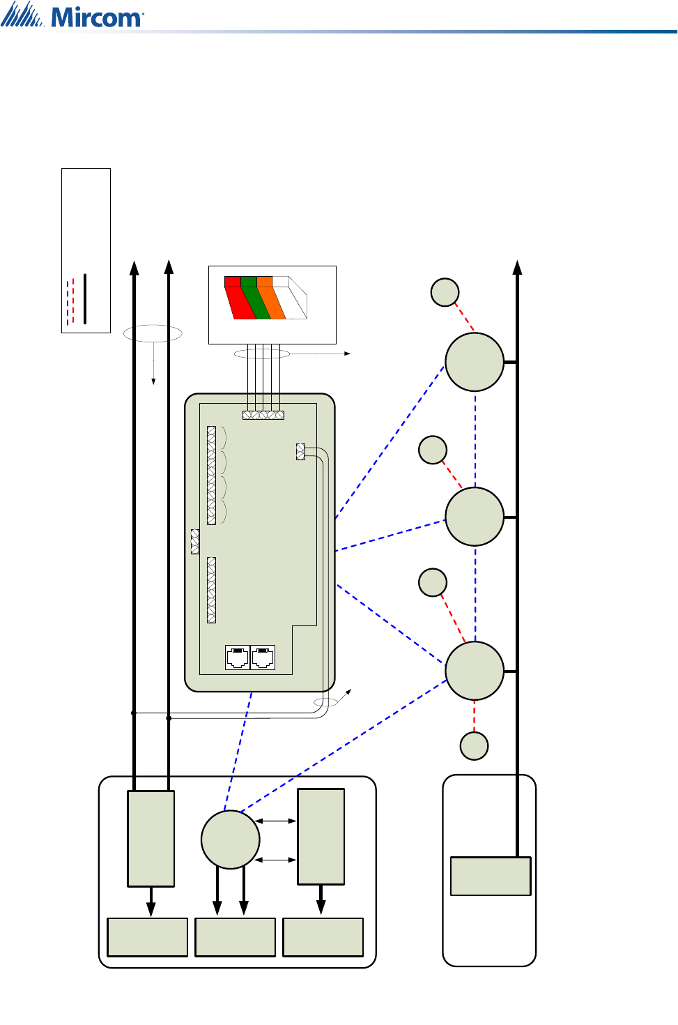
836
%$&.83
32:(5
&225',1$725
%81'/(
1&.
6(59(55220
9'&3RZHU6XSSO\
5%0'
0L&DUH6HUYHU(TXLSPHQW
Z1&6:
&20
/2:
+,*+
2XWSXW
2XWSXW
2XWSXW
2XWSXW
,QSXW
*1'
,QSXW
*1'
,QSXW
*1'
,QSXW
*1'
1&&121&&121&&12 1&&12
2XWSXW
2XWSXW
2XWSXW
2XWSXW
*1'
5HG
$PEHU
*UHHQ
:KLWH
%URZQ
3LQ
3LQ
&1
/LQH,Q
&1
([W
&1 &1
&1
&1
&1
9'&:DOO
$GDSWHU
9$&
9'&:DOO
$GDSWHU
9$&
86%
&RQQHFWLRQ
86%
&RQQHFWLRQ
:LUH7\SH$:*
:LUH7\SH$:* :LUH7\SH$:*
7R$GGLWLRQDO1&V
1&
'RPH/LJKW
836
%$&.83
32:(5
836
%$&.83
32:(5
9$&
836
%$&.83
32:(5
(/(&75,&$/5220
/$/$ /$/$ /$/$
5P"EEJUJPOBM/$/$T
1&
1&
1&1&
*+]=LJEHH:LUHOHVV&RQQHFWLRQ
/(*(1'
+DUG:LUHG&RQQHFWLRQ
1RWH1&1&DQG1&DUHEDWWHU\SRZHUHG
10.0 Appendix 3: Wiring Diagram for
Emergency Call System (UL 2560)
58
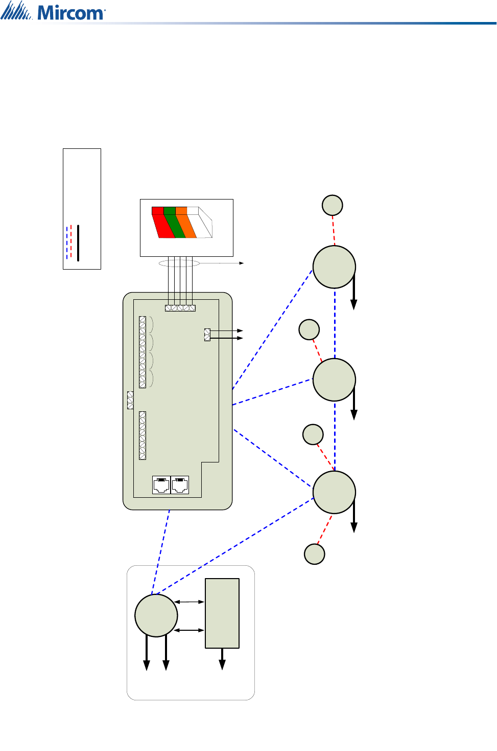
&225',1$725
%81'/(
1&.
6(59(552201856(5220
0L&DUH6HUYHU(TXLSPHQW
Z1&6:
&20
/2:
+,*+
2XWSXW
2XWSXW
2XWSXW
2XWSXW
,QSXW
*1'
,QSXW
*1'
,QSXW
*1'
,QSXW
*1'
1&&121&&121&&12 1&&12
2XWSXW
2XWSXW
2XWSXW
2XWSXW
*1'
5HG
$PEHU
*UHHQ
:KLWH
%URZQ
3LQ
3LQ
&1
/LQH,Q
&1
([W
&1 &1
&1
&1
&1
9'&:DOO
$GDSWHU
9'&:DOO
$GDSWHU
9$&
86%
&RQQHFWLRQ
86%
&RQQHFWLRQ
:LUH7\SH$:*
1&
'RPH/LJKW
/$/$ /$/$ /$/$
1&
1&
1&
1&
*+]=LJEHH:LUHOHVV&RQQHFWLRQ
/(*(1'
9$& 9$& 9$&
9'&
+DUG:LUHG&RQQHFWLRQ
1RWH1&1&DQG1&DUHEDWWHU\SRZHUHG
11.0 Appendix 4: Wiring Diagram for
Nurse Call System (UL 1069)

59
12.0 Appendix 5: Device Installation
Table
Use the following table to keep track of the devices you install and where they are located.
This information should be passed along to the administrator of the MiCare Central server so
that the devices can be added to the Nurse Call and Emergency System.
Table 5 Device installation table
Device MAC Address
Device Type
Building
Wing
Floor
Room
Patient Unit
Beacon
Pull Station
Pendant
Staff Badge
Asset Tag
ZF3

60
Appendix 5: Device Installation Table
Table 5 Device installation table (Continued)
Device MAC Address
Device Type
Building
Wing
Floor
Room
Patient Unit
Beacon
Pull Station
Pendant
Staff Badge
Asset Tag
ZF3

61
13.0 Warranty and Warning Information
WARNING!
Please read this document CAREFULLY, as it contains important warnings, life-safety, and
practical information about all products manufactured by the Mircom Group of Companies,
including Mircom and Secutron branded products, which shall include without limitation all fire
alarm, nurse call, building automation and access control and card access products
(hereinafter individually or collectively, as applicable, referred to as “Mircom System”).
NOTE TO ALL READERS:
1. Nature of Warnings. The within warnings are communicated to the reader out of an
abundance of caution and create no legal obligation for Mircom Group of Companies,
whatsoever. Without limiting the generality of the foregoing, this document shall NOT be
construed as in any way altering the rights and obligations of the parties, governed by the legal
documents that apply in any given circumstance.
2. Application. The warnings contained in this document apply to all Mircom System and shall
be read in conjunction with:
a. the product manual for the specific Mircom System that applies in given circumstances;
b. legal documents that apply to the purchase and sale of a Mircom System, which may
include the company’s standard terms and conditions and warranty statements;
c. other information about the Mircom System or the parties’ rights and obligations as may
be application to a given circumstance.
3. Security and Insurance. Regardless of its capabilities, no Mircom System is a substitute for
property or life insurance. Nor is the system a substitute for property owners, renters, or other
occupants to act prudently to prevent or minimize the harmful effects of an emergency
situation. Building automation systems produced by the Mircom Group of Companies are not
to be used as a fire, alarm, or life-safety system.
NOTE TO INSTALLERS:
All Mircom Systems have been carefully designed to be as effective as possible. However,
there are circumstances where they may not provide protection. Some reasons for system
failure include the following. As the only individual in contact with system users, please bring
each item in this warning to the attention of the users of this Mircom System. Failure to
properly inform system end-users of the circumstances in which the system might fail may
result in over-reliance upon the system. As a result, it is imperative that you properly inform
each customer for whom you install the system of the possible forms of failure:
4. Inadequate Installation. All Mircom Systems must be installed in accordance with all the
applicable codes and standards in order to provide adequate protection. National standards
require an inspection and approval to be conducted by the local authority having jurisdiction
following the initial installation of the system and following any changes to the system. Such
inspections ensure installation has been carried out properly.
5. Inadequate Testing. Most problems that would prevent an alarm a Mircom System from
operating as intended can be discovered by regular testing and maintenance. The complete
system should be tested by the local authority having jurisdiction immediately after a fire,
storm, earthquake, accident, or any kind of construction activity inside or outside the premises.

62
Warranty and Warning Information
The testing should include all sensing devices, keypads, consoles, alarm indicating devices
and any other operational devices that are part of the system.
NOTE TO USERS:
All Mircom Systems have been carefully designed to be as effective as possible. However,
there are circumstances where they may not provide protection. Some reasons for system
failure include the following. The end user can minimize the occurrence of any of the following
by proper training, testing and maintenance of the Mircom Systems:
6. Inadequate Testing and Maintenance. It is imperative that the systems be periodically
tested and subjected to preventative maintenance. Best practices and local authority having
jurisdiction determine the frequency and type of testing that is required at a minimum. Mircom
System may not function properly, and the occurrence of other system failures identified below
may not be minimized, if the periodic testing and maintenance of Mircom Systems is not
completed with diligence and as required.
7. Improper Operation. It is important that all system users be trained in the correct operation
of the alarm system and that they know how to respond when the system indicates an alarm.
A Mircom System may not function as intended during an emergency situation where the user
is unable to operate a panic or emergency switch by reason of permanent or temporary
physical disability, inability to reach the device in time, unfamiliarity with the correct operation,
or related circumstances.
8. Insufficient Time. There may be circumstances when a Mircom System will operate as
intended, yet the occupants will not be protected from the emergency due to their inability to
respond to the warnings in a timely manner. If the system is monitored, the response may not
occur in time enough to protect the occupants or their belongings.
9. Carelessness or Safety Hazards. Moreover, smoke detectors may not provide timely
warning of fires caused by carelessness or safety hazards such as smoking in bed, violent
explosions, escaping gas, improper storage of flammable materials, overloaded electrical
circuits or children playing with matches or arson.
10. Power Failure. Some Mircom System components require adequate electrical power supply
to operate. Examples include: smoke detectors, beacons, HVAC, and lighting controllers. If a
device operates only by AC power, any interruption, however brief, will render that device
inoperative while it does not have power. Power interruptions of any length are often
accompanied by voltage fluctuations which may damage Mircom Systems or other electronic
equipment. After a power interruption has occurred, immediately conduct a complete system
test to ensure that the system operates as intended.
11. Battery Failure. If the Mircom System or any device connected to the system operates from
batteries it is possible for the batteries to fail. Even if the batteries have not failed, they must be
fully charged, in good condition, and installed correctly. Some Mircom Systems use
replaceable batteries, which have a limited life-span. The expected battery life is variable and
in part dependent on the device environment, usage and type. Ambient conditions such as
high humidity, high or low temperatures, or large temperature fluctuations may reduce the
expected battery life. Moreover, some Mircom Systems do not have a battery monitor that
would alert the user in the event that the battery is nearing its end of life. Regular testing and
replacements are vital for ensuring that the batteries function as expected, whether or not a
device has a low-battery monitor.
12. Physical Obstructions. Motion sensors that are part of a Mircom System must be kept clear
of any obstacles which impede the sensors’ ability to detect movement. Signals being
communicated by a Mircom System may not reach the receiver if an item (such as metal,
water, or concrete) is placed on or near the radio path. Deliberate jamming or other
inadvertent radio signal interference can also negatively affect system operation.

63
Warranty and Warning Information
13. Wireless Devices Placement Proximity. Moreover all wireless devices must be a minimum
and maximum distance away from large metal objects, such as refrigerators. You are required
to consult the specific Mircom System manual and application guide for any maximum
distances required between devices and suggested placement of wireless devices for optimal
functioning.
14. Failure to Trigger Sensors. Moreover, Mircom Systems may fail to operate as intended if
motion, heat, or smoke sensors are not triggered.
a. Sensors in a fire system may fail to be triggered when the fire is in a chimney, walls, roof,
or on the other side of closed doors. Smoke and heat detectors may not detect smoke
or heat from fires on another level of the residence or building. In this situation the
control panel may not alert occupants of a fire.
b. Sensors in a nurse call system may fail to be triggered when movement is occurring
outside of the motion sensors’ range. For example, if movement is occurring on the other
side of closed doors or on another level of the residence or building the motion detector
may not be triggered. In this situation the central controller may not register an alarm
signal.
15. Interference with Audible Notification Appliances. Audible notification appliances may be
interfered with by other noise sources such as stereos, radios, televisions, air conditioners,
appliances, or passing traffic. Audible notification appliances, however loud, may not be heard
by a hearing-impaired person.
16. Other Impairments. Alarm notification appliances such as sirens, bells, horns, or strobes
may not warn or waken a sleeping occupant if there is an intervening wall or door. It is less
likely that the occupants will be alerted or awakened when notification appliances are located
on a different level of the residence or premise.
17. Software Malfunction. Most Mircom Systems contain software. No warranties are provided
as to the software components of any products or stand-alone software products within a
Mircom System. For a full statement of the warranties and exclusions and limitations of
liability please refer to the company’s standard Terms and Conditions and Warranties.
18. Telephone Lines Malfunction. Telephone service can cause system failure where telephone
lines are relied upon by a Mircom System. Alarms and information coming from a Mircom
System may not be transmitted if a phone line is out of service or busy for a certain period of
time. Alarms and information may not be transmitted where telephone lines have been
compromised by criminal tampering, local construction, storms or earthquakes.
19. Component Failure. Although every effort has been made to make this Mircom System as
reliable as possible, the system may fail to function as intended due to the failure of a
component.
20. Integrated Products. Mircom System might not function as intended if it is connected to a
non-Mircom product or to a Mircom product that is deemed non-compatible with a particular
Mircom System. A list of compatible products can be requested and obtained.
Warranty
Purchase of all Mircom products is governed by:
https://www.mircom.com/product-warranty
https://www.mircom.com/purchase-terms-and-conditions
https://www.mircom.com/software-license-terms-and-conditions

64
14.0 Special Notices
FCC Regulatory Statements
This device complies with Part 15 of the FCC Rules. Operation is subject to the following two
conditions:
(1) This device may not cause harmful interference.
(2) This device must accept any interference received, including interference that may cause
undesired operation.
This equipment has been tested and found to comply with the limits for a Class B digital
device, pursuant to part 15 of the Federal Communication Commission (FCC) rules. These
limits are designed to provide reasonable protection against harmful interference in a
residential installation. This equipment generates, uses and can radiate radio frequency
energy and, if not installed and used in accordance with the instructions, may cause harmful
interference to radio communications. However, there is no guarantee that interference will not
occur in a particular installation. If this equipment causes harmful interference to radio or
television reception, which can be determined by turning the equipment off and on, the user is
encouraged to try to correct the interference by doing one or more of the following measures:
• Reorient or relocate the receiving antenna.
• Increase the separation between the equipment and receiver.
• Connect the equipment into an outlet on a circuit different from that to which the receiver
is connected.
• Consult the dealer or an experienced radio/TV technician for help.
NOTE: THE GRANTEE IS NOT RESPONSIBLE FOR ANY CHANGES OR MODIFICATIONS
NOT EXPRESSLY APPROVED BY THE PARTY RESPONSIBLE FOR COMPLIANCE. SUCH
MODIFICATIONS COULD VOID THE USER’S AUTHORITY TO OPERATE THE
EQUIPMENT.
RF Exposure Warning
This equipment complies with FCC radiation exposure limits set forth for an uncontrolled
environment. In order to avoid the possibility of exceeding the FCC radio frequency exposure
limits, human proximity to the antenna shall not be less than 20 cm during normal operation
and must not be co-located or operating in conjunction with any other antenna or transmitter.
ISED Regulatory Statements
This device complies with ISED Canada license-exempt RSS standard(s). Operation is
subject to the following two conditions: (1) this device may not cause interference, and (2) this
device must accept any interference, including interference that may cause undesired
operation of the device.
Le présent appareil est conforme avec ISED Canada applicables aux appareils radio exempts
de licence. L'exploitation est autorisée aux deux conditions suivantes: (1) l'appareil ne doit pas
produire de brouillage, et (2) l'utilisateur de l'appareil doit accepter tout brouillage
radioélectrique subi, même si le brouillage est susceptible d'en compromettre le
fonctionnement.
CAN ICES-3 (B)/NMB-3(B)

65
Special Notices
RF Exposure Information
This equipment complies with ISED RSS-102 radiation exposure limits set forth for an
uncontrolled environment. This transmitter must be installed to provide a separation distance
of at least 20 cm from all persons and must not be co-located or operating in conjunction with
any other antenna or transmitter.
Cet équipement est conforme avec ISED RSS-102 des limites d'exposition aux rayonnements
définies pour un environnement non contrôlé. Cet émetteur doit être installé à au moins 20 cm
de toute personne et ne doit pas être colocalisé ou fonctionner en association avec une autre
antenne ou émetteur.

U.S.A
4575 Witmer Industrial Estates
Niagara Falls, NY 14305
Tel: (905) 660-4655
(888) 660-4655
Fax: (905) 660-4113
© Mircom 2018
Printed in Canada
Subject to change without prior notice
www.mircom.com
CANADA - Main Office
25 Interchange Way
Vaughan, ON L4K 5W3
Tel: (905) 660-4655
(888) 660-4655
Fax: (905) 660-4113