Mitac Digital Technology LBP01 WLAN PCMCIA Card User Manual Revised Users Manual
Mitac International Corporation WLAN PCMCIA Card Revised Users Manual
UserManual.wiki
>
Mitac Digital Technology
>
LBP01 User Manual
>
Revised Users Manual
Contents
1.
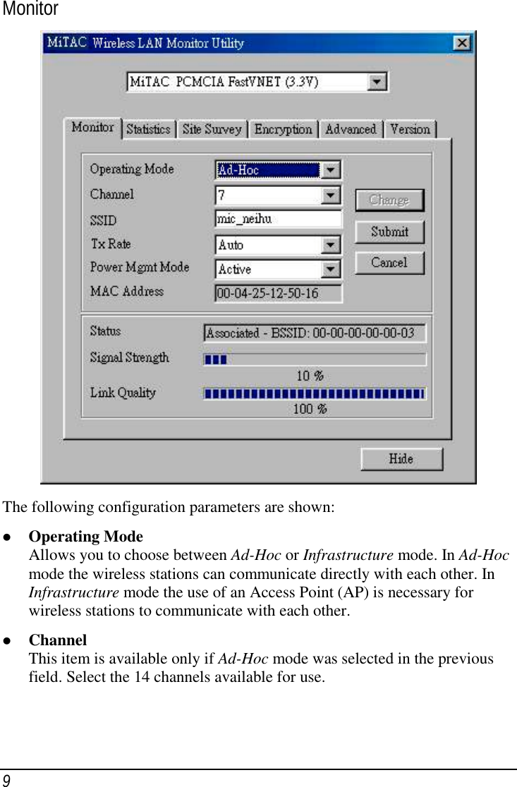
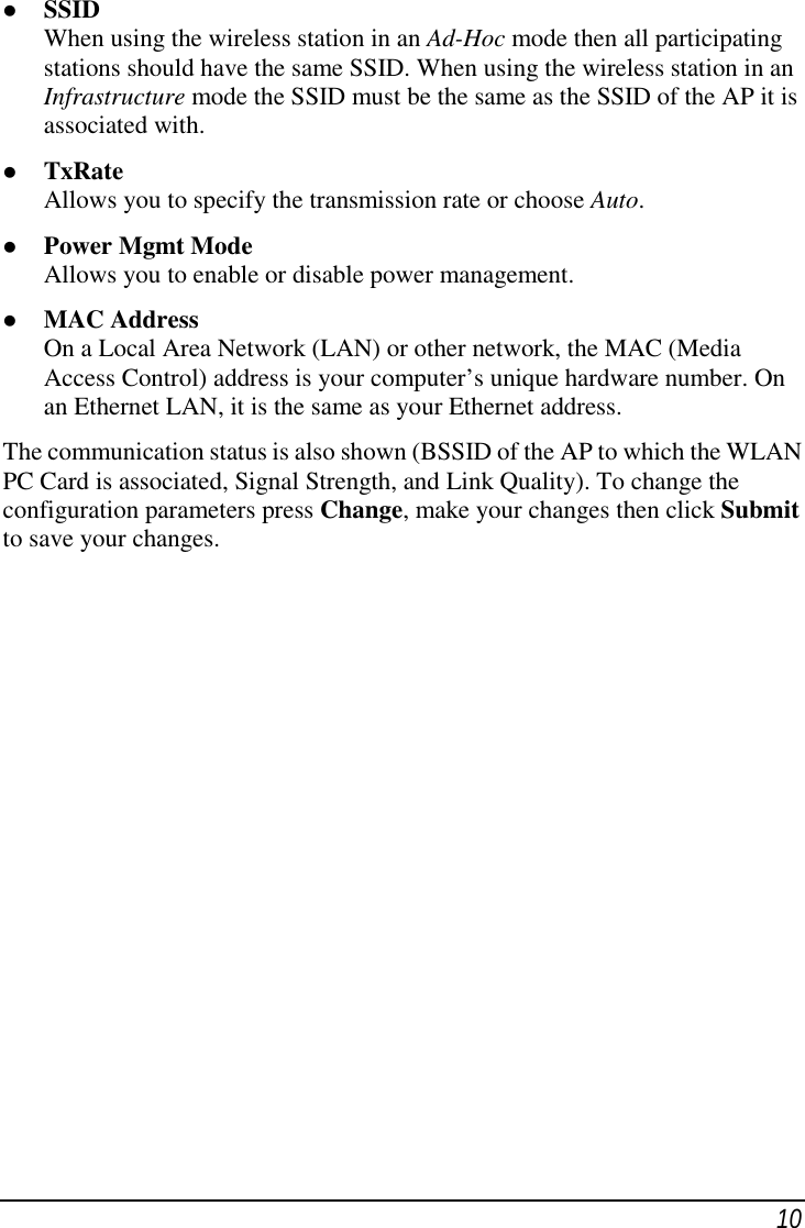
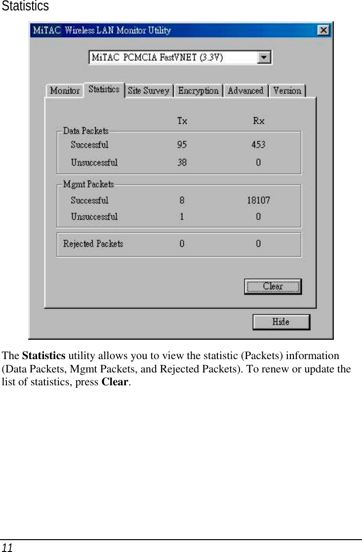
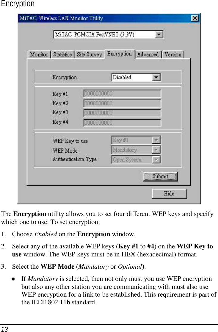
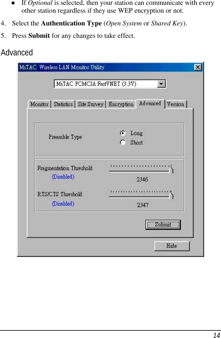
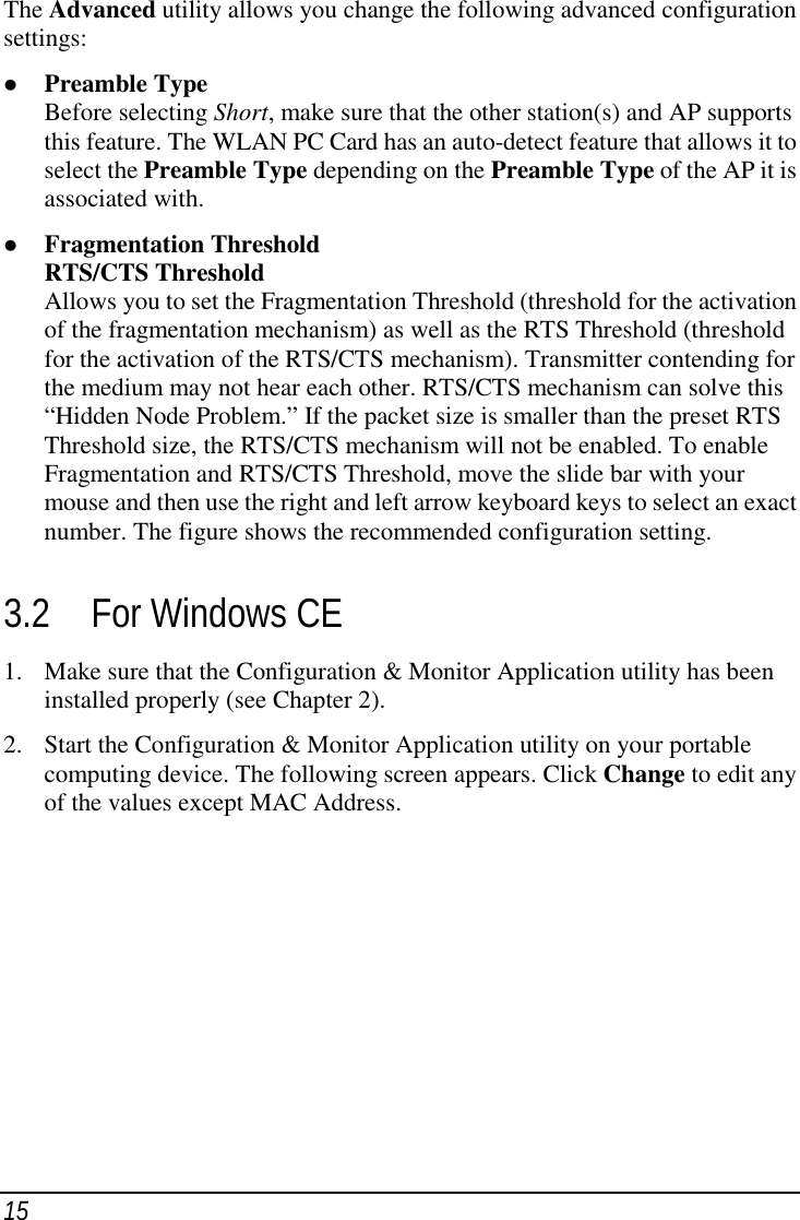
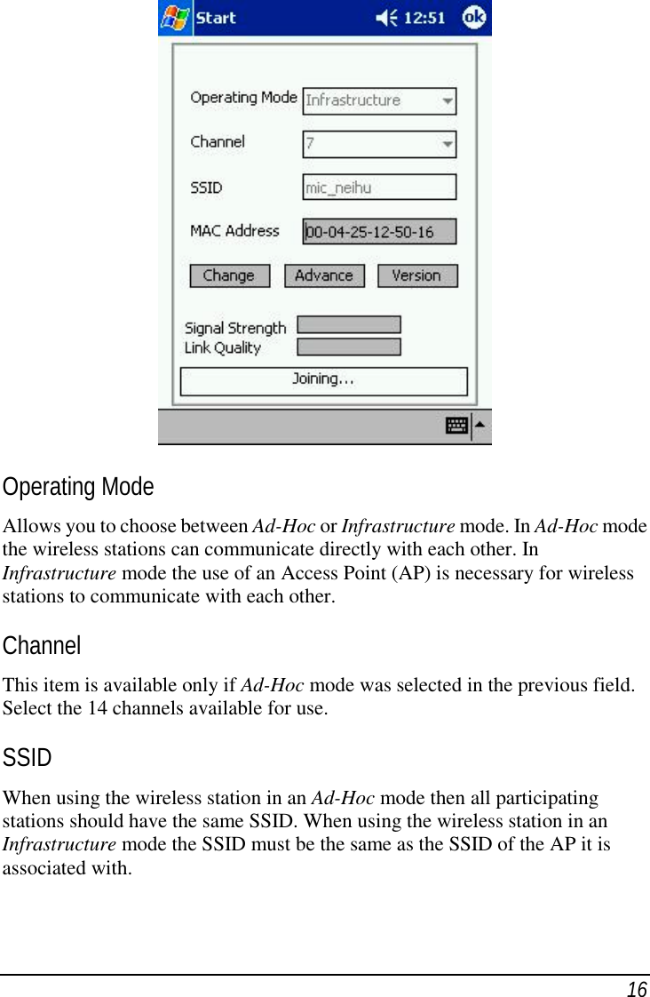
Revised Users Manual
2.
DoC Statement
Revised Users Manual
Navigation menu
Upload a User Manual
Namespaces
Wiki Guide
HTML
PDF
Info
Views
User Manual
Discussion / Help
Navigation