Mitac Digital Technology LBP01 WLAN PCMCIA Card User Manual Revised Users Manual
Mitac International Corporation WLAN PCMCIA Card Revised Users Manual
Contents
- 1. Revised Users Manual
- 2. DoC Statement
Revised Users Manual
LBP01
User’s Manual
(December 2001)
TRADEMARKS
All brand and product names are trademarks or registered trademarks of their
respective companies.
NOTE
Information in this manual is subject to change without notice.

i
0 Table of Contents
Regulations Information..........................................................ii
Safety Precautions..................................................................ii
1 Introduction ..........................................................................1
1.1 Product Description................................................................. 1
1.2 Product View........................................................................... 2
2 Setting Up .............................................................................3
2.1 System Requirements............................................................. 3
2.2 Installing the Driver and Utility................................................. 3
For Windows 98/Me/2000 ...................................................... 3
For Windows CE.................................................................... 6
2.3 Inserting the WLAN PC Card...................................................6
2.4 Removing the WLAN PC Card ................................................ 7
3 Using Configuration & Monitor Application Utility............8
3.1 For Windows 98/Me/2000 ....................................................... 8
3.2 For Windows CE ................................................................... 15
A Appendix.............................................................................19
A.1 Specifications........................................................................ 20
A.2 Uninstalling the Utility and Driver........................................... 20
Configuration & Monitor Application Utility ........................... 20
WLAN PC Card.................................................................... 20

ii
Regulations Information
Federal Communications Commission Interference Statement
This equipment has been tested and found to comply with the limits for a Class B digital device
pursuant to Part 15 of the FCC Rules. These limits are designed to provide reasonable protection
against harmful interference in a residential installation. This equipment generates, uses, and can
radiate radio frequency energy and, if not installed and used in accordance with the instructions,
may cause harmful interference to radio communications. However, there is no guarantee that
interference will not occur in a particular installation. If this equipment does cause harmful
interference to radio or television reception, which can be determined by turning the equipment
off and on, the user is encouraged to try to correct the interference by one or more of the following
measures:
Reorient or relocate the receiving antenna.
Increase the separation between the equipment and receiver.
Connect the equipment into an outlet on a circuit different from that to which the receiver is
connected.
Consult the dealer or an experienced radio/TV technician for help.
FCC Caution:
To ensure continued compliance, use only shielded interface cables when connecting to computer
or peripheral devices. Any changes or modifications not expressly approved by the party
responsible for compliance could void the user’s authority to operate this equipment.
This device complies with Part 15 of the FCC Rules. Operation is subject to the following two
conditions:
1. This device may not cause harmful interference, and
2. This device must accept any interference received, including interference that may cause
undesired operation.
Important Note:
FCC Radiation Exposure Statement:
This equipment complies with FCC radiation exposure limits set forth for an uncontrolled
environment. This equipment should be installed and operated with minimum distance of 20
cm between the radiator and your body.
This transmitter must not be co-located or operated in conjunction with any other antenna or
transmitter.

iii
Safety Precautions
Be sure to read and follow all warning notices and instructions.
In order to extend the life of the device it is advised to store it in a protective
casing whenever carrying the computing device on travel and not operating
the device.
Never use abrasive materials or rinse the device with liquids.
At all times, it will be the responsibility of the end-user to ensure that an
outdoor antenna installation complies with local radio regulations.
Do not service the product by yourself. Refer all servicing to qualified
service personnel.
In order to limit Radio Frequency (RF) exposure, the following rules should
be applied:
– Install the antenna in a location where a distance of 20 cm from the
antenna may be maintained.
– While installing the antenna in the location, please do not turn on
power of the device.
– While the device is working (transmitting or receiving), please do not
touch or move the antenna.
– Do not operate a portable transmitter near unshielded blasting caps or
in an explosive environment unless it is a type especially qualified for
such use.

1
1 Introduction
This chapter introduces the features and functions of the product.
1.1 Product Description
Congratulations on purchasing this PCMCIA Wireless Local Area Network
(WLAN) Card.
Your WLAN PC Card’s 11 Mbps data rate provides an equivalent Ethernet
speed to access corporate networks or the Internet in a wireless environment.
When installed, the WLAN PC Card is able to communicate with any
802.11b-compliant product, allowing you to work anywhere in the coverage
area, enjoying its convenience and mobility.
Your PC Card features:
IEEE 802.11b and Wi-Fi-compliant 11 Mbps WLAN access solution
Seamless wireless roaming
Direct Sequence Spread Spectrum (DSSS) standard
Wired Equivalent Privacy (WEP) 128-bit data encryption
Frequency range at 2.4 GHz ISM band
Automatic data rate selection at 11 Mbps, 5.5 Mbps, 2 Mbps, and 1 Mbps
PCMCIA Type II Plug-and-Play
High sensitivity and output power
2
Typical applications include:
IEEE 802.11b-compliant WLAN radio
Portable PC wireless modem
Point-to-Point data
Wireless home networking
Small Office Home Office (SOHO) wireless application
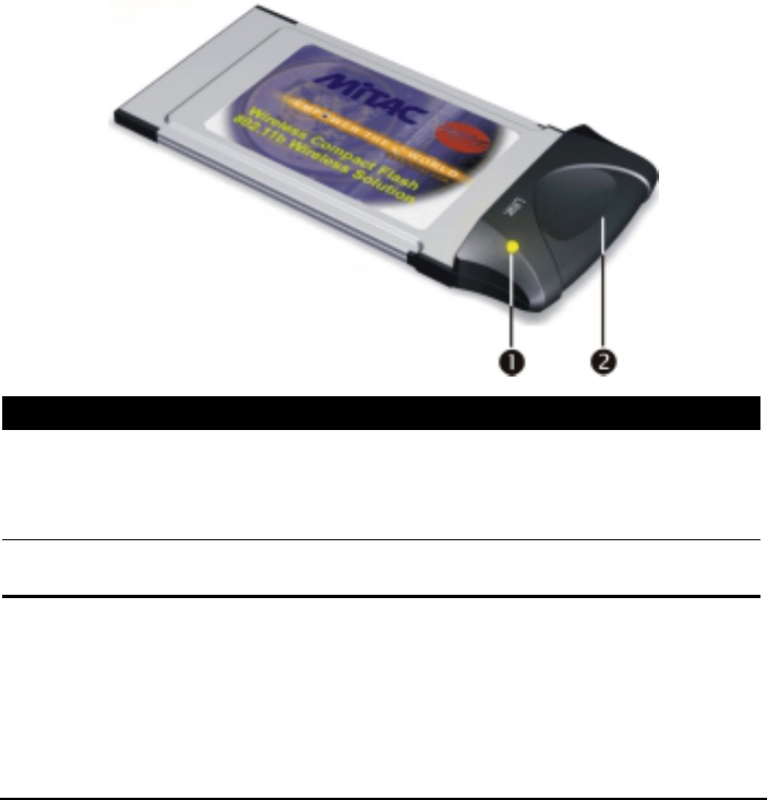
1.2 Product View
Ref Component Description
Power and
Transmit/Receive
Indicator
Glows red when the WLAN PC Card is inserted into a
PCMCIA slot and is deriving power from it.
Glows green when the WLAN PC Card is sensing/
transmitting wireless data.
Integrated
Antenna Allows the WLAN PC Card to receive and transmit
wireless data.

3
2 Setting Up
This chapter tells you how to setup the device for use.
2.1 System Requirements
To use the device, you need:
Operating system: Windows 98, Windows Me, Windows 2000,
Windows CE
Available PCMCIA slot on your computing device
Driver CD
Windows installation disks (in case you are prompted for the operating
system files)
2.2 Installing the Driver and Utility
CAUTION: Do not insert your WLAN PC Card into the PCMCIA slot at this stage until you
are required to do so.
For Windows 98/Me/2000
NOTE: When using Windows 2000 and before proceeding, make sure you have logged on
as “Administrator.”
1. Insert the driver CD into the CD-ROM drive and double-click the file
SETUP.EXE under the Win98_Me_2000 directory.
2. Follow the onscreen instructions to continue.
4
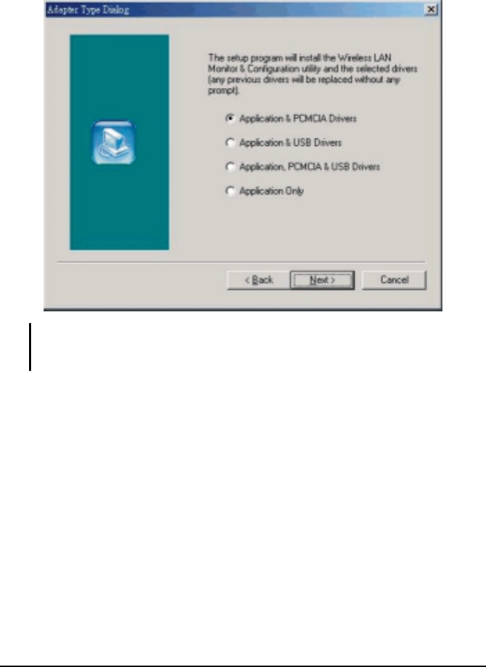
3. When the next screen appears, select the first option “Application &
PCMCIA Drivers” to install the utility (Configuration and Monitor
Application) and the WLAN PC Card driver.
NOTE: If the WLAN PC Card driver have been previously installed and have not been
uninstalled prior to this latest installation, the new driver will overwrite the old one without
prompting you.
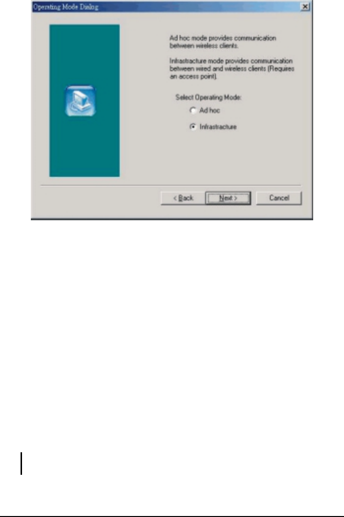
4. After you have confirmed the driver’s “Destination Location” as well as the
“Program Folders,” choose the mode of operation whether Ad-Hoc or
Infrastructure on the Operating Mode Dialog window.
5
Ad-Hoc Mode
In Ad-Hoc mode the wireless stations can communicate directly with
each other.
When selecting the Ad-Hoc mode you need to specify the ESSID and
the Channel parameters.
– ESSID: All stations participating in the Ad-Hoc network should
have the same ESSID.
– Channel: Select the 14 channels available for use.
Infrastructure Mode
In Infrastructure mode the use of an Access Point (AP) is necessary for
wireless stations to communicate with each other.
When selecting the Infrastructure mode you need to specify the ESSID.
– ESSID: Specify the ESSID of the AP to which the wireless station
will be associated with.
NOTE: You can still change the Operating Mode afterwards using the Configuration &
Monitor Application utility.

6
5. After you have made your selection, click Next and a window listing your
installation setting appears. If the settings are correct, click Next to
continue. In case you made a mistake, click Back to make the correction and
follow the onscreen instructions to exit the installation.
NOTE: For Windows 2000, select Yes when the “Digital Signature Not Found” window
appears.
6. Re-boot your system after completing the installation.
For Windows CE
1. Insert the driver CD into the CD-ROM drive and double-click the file
SETUP.EXE under the WinCE directory.
2. Follow the onscreen instructions to continue.
3. Re-boot your system after completing the installation.
2.3 Inserting the WLAN PC Card
NOTE: Make sure that the WLAN PC Card’s driver as well as the Configuration & Monitor
Application utility has been properly installed (see previous section).
1. Find an available Type II PCMCIA slot in your computing device
2. With the WLAN PC Card adapter’s 68-pin connector facing the PCMCIA
slot, slide the card completely into the slot (refer to your system manual for
the correct orientation).
NOTE: If you have never installed the driver of the PCMCIA slot of your system, then
Windows® would automatically detect the new hardware and may prompt you to install it.
Have the Windows installation CD ready (in case you are prompted for it) and follow the
onscreen instructions to install the driver.

7
2.4 Removing the WLAN PC Card
The PCMCIA slot permits “hot swapping” of PC Card, allowing you to insert or
remove the WLAN PC Card from the slot whenever you like, even when the
power to your computer is on. However, you are advised to always disable the
WLAN PC Card prior to removing it from the PCMCIA slot. This allows the
Windows® operating system to log off from the network server, disable the
driver properly through the Control Panel, and disconnect power to the
PCMCIA slot.

8
3 Using the Configuration &
Monitor Application Utility
In special circumstances, you may need to change configuration settings
depending on how you would like to manage your wireless network. The
Configuration & Monitor Application utility enables you to make configuration
changes and perform user-level diagnostics on your WLAN PC Card as well as
monitor the status of communication.
3.1 For Windows 98/Me/2000
1. Make sure that the Configuration & Monitor Application utility has been
installed properly (see Chapter 2).
2. As soon as a link is established, the Configuration & Monitor Application
utility appears as an icon on the Windows’ system tray. Double-click on this
icon.
NOTES:
When the station is in Infrastructure mode and not associated with an AP, color of the
icon is red.
When the station is in Infrastructure mode and associated with an AP, color of icon is
blue.
When the station is in Ad-Hoc mode, color of icon is always blue.
When the station is in Ad-Hoc mode and the WLAN PC Card is resetting and
initializing, color of icon is red.
3. When the Configuration & Monitor Application utility appears onscreen,
make sure that “PCMCIA Card” is selected on the very top of the window.
9
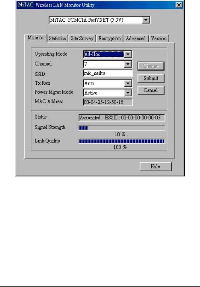
Monitor
The following configuration parameters are shown:
Operating Mode
Allows you to choose between Ad-Hoc or Infrastructure mode. In Ad-Hoc
mode the wireless stations can communicate directly with each other. In
Infrastructure mode the use of an Access Point (AP) is necessary for
wireless stations to communicate with each other.
Channel
This item is available only if Ad-Hoc mode was selected in the previous
field. Select the 14 channels available for use.

10
SSID
When using the wireless station in an Ad-Hoc mode then all participating
stations should have the same SSID. When using the wireless station in an
Infrastructure mode the SSID must be the same as the SSID of the AP it is
associated with.
TxRate
Allows you to specify the transmission rate or choose Auto.
Power Mgmt Mode
Allows you to enable or disable power management.
MAC Address
On a Local Area Network (LAN) or other network, the MAC (Media
Access Control) address is your computer’s unique hardware number. On
an Ethernet LAN, it is the same as your Ethernet address.
The communication status is also shown (BSSID of the AP to which the WLAN
PC Card is associated, Signal Strength, and Link Quality). To change the
configuration parameters press Change, make your changes then click Submit
to save your changes.
11
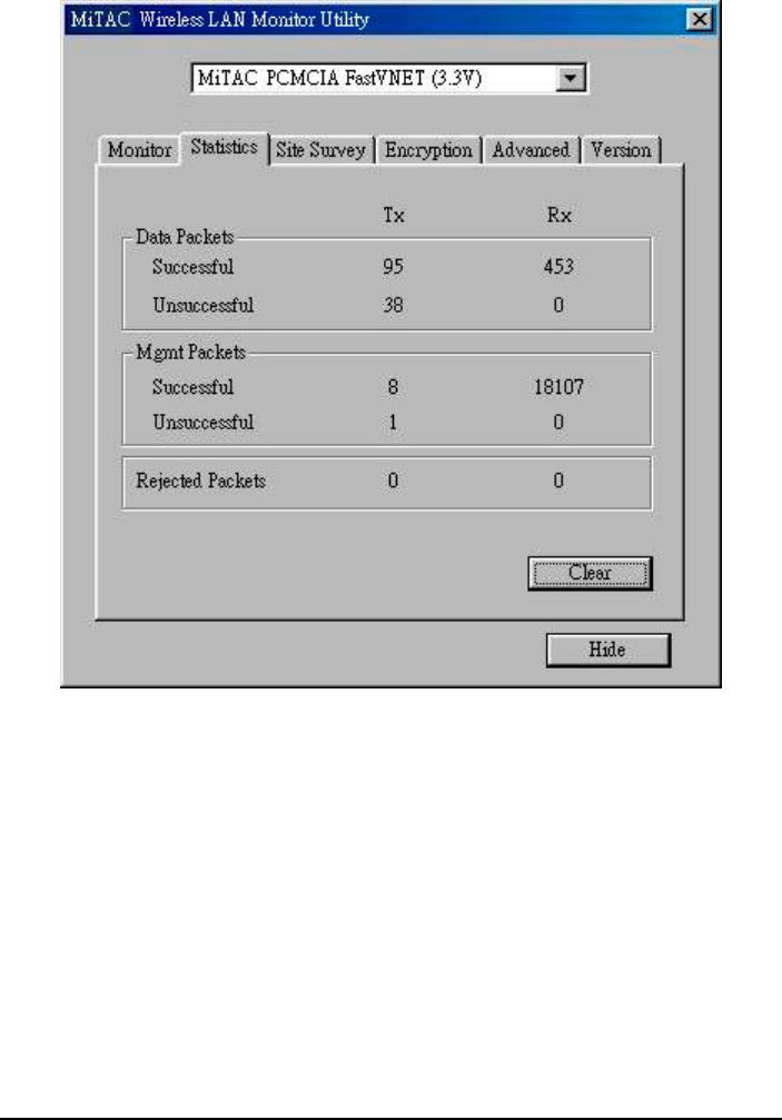
Statistics
The Statistics utility allows you to view the statistic (Packets) information
(Data Packets, Mgmt Packets, and Rejected Packets). To renew or update the
list of statistics, press Clear.
12
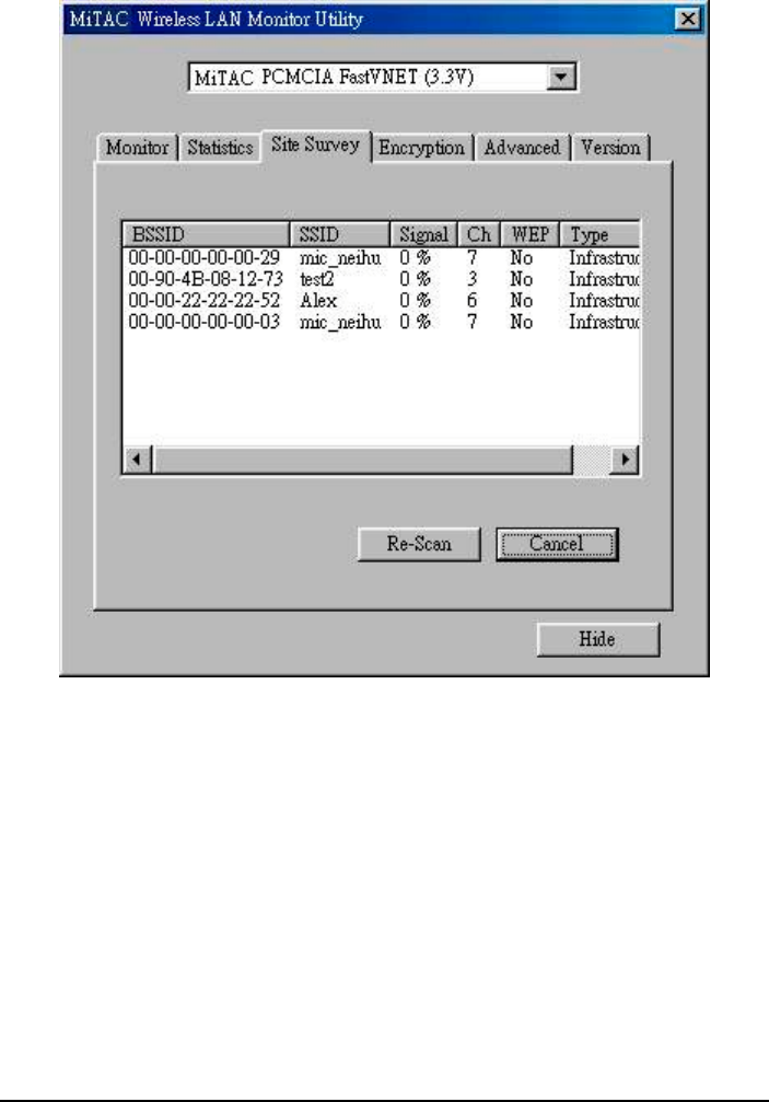
Site Survey
The Site Survey utility allows you to scan all the channels to locate all the APs
(Access Points) within range of your WLAN PC Card. When an/various AP(s)
are located, information regarding the BSSID and SSID, signal strength and
channel where the AP operates, whether or not WEP encryption is used, and the
operating mode is shown. Click Re-Scan to update the list.
To associate with any of the APs listed, double-click on your choice (on the
BSSID field) and the utility will take you back to the Monitor utility showing
you the parameters of the newly established connection.
13
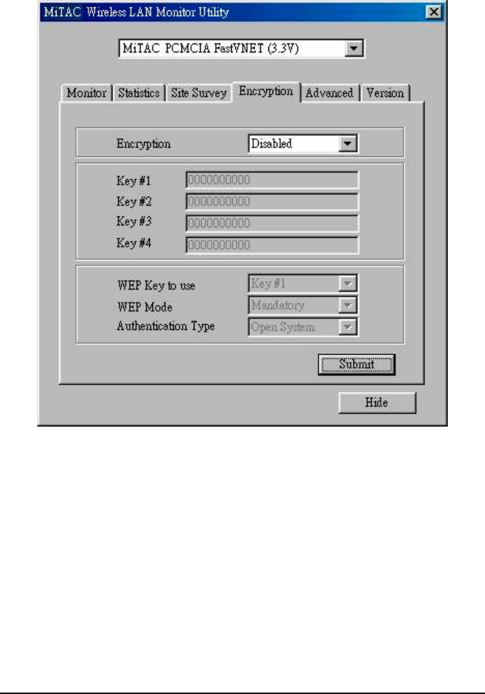
Encryption
The Encryption utility allows you to set four different WEP keys and specify
which one to use. To set encryption:
1. Choose Enabled on the Encryption window.
2. Select any of the available WEP keys (Key #1 to #4) on the WEP Key to
use window. The WEP keys must be in HEX (hexadecimal) format.
3. Select the WEP Mode (Mandatory or Optional).
If Mandatory is selected, then not only must you use WEP encryption
but also any other station you are communicating with must also use
WEP encryption for a link to be established. This requirement is part of
the IEEE 802.11b standard.
14
If Optional is selected, then your station can communicate with every
other station regardless if they use WEP encryption or not.
4. Select the Authentication Type (Open System or Shared Key).
5. Press Submit for any changes to take effect.
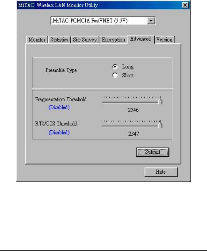
Advanced

15
The Advanced utility allows you change the following advanced configuration
settings:
Preamble Type
Before selecting Short, make sure that the other station(s) and AP supports
this feature. The WLAN PC Card has an auto-detect feature that allows it to
select the Preamble Type depending on the Preamble Type of the AP it is
associated with.
Fragmentation Threshold
RTS/CTS Threshold
Allows you to set the Fragmentation Threshold (threshold for the activation
of the fragmentation mechanism) as well as the RTS Threshold (threshold
for the activation of the RTS/CTS mechanism). Transmitter contending for
the medium may not hear each other. RTS/CTS mechanism can solve this
“Hidden Node Problem.” If the packet size is smaller than the preset RTS
Threshold size, the RTS/CTS mechanism will not be enabled. To enable
Fragmentation and RTS/CTS Threshold, move the slide bar with your
mouse and then use the right and left arrow keyboard keys to select an exact
number. The figure shows the recommended configuration setting.
3.2 For Windows CE
1. Make sure that the Configuration & Monitor Application utility has been
installed properly (see Chapter 2).
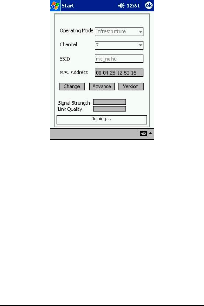
2. Start the Configuration & Monitor Application utility on your portable
computing device. The following screen appears. Click Change to edit any
of the values except MAC Address.
16
Operating Mode
Allows you to choose between Ad-Hoc or Infrastructure mode. In Ad-Hoc mode
the wireless stations can communicate directly with each other. In
Infrastructure mode the use of an Access Point (AP) is necessary for wireless
stations to communicate with each other.
Channel
This item is available only if Ad-Hoc mode was selected in the previous field.
Select the 14 channels available for use.
SSID
When using the wireless station in an Ad-Hoc mode then all participating
stations should have the same SSID. When using the wireless station in an
Infrastructure mode the SSID must be the same as the SSID of the AP it is
associated with.
17
MAC Address
On a Local Area Network (LAN) or other network, the MAC (Media Access
Control) address is your computer’s unique hardware number. On an Ethernet
LAN, it is the same as your Ethernet address.
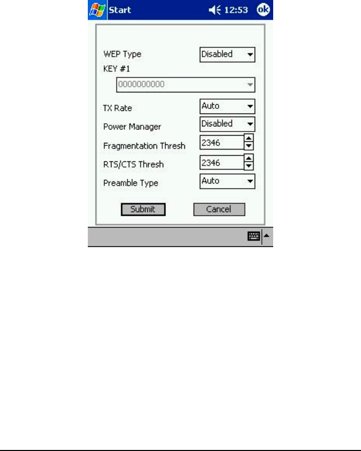
Upon clicking Advance, the following screen appears:
WEP Type
Allows you to choose between 64 Bit and 128 Bit, or disable WEP encryption.
Key #1 ~ #4
Select any of the available WEP keys (Key #1 to #4). When 64 Bit WEP Type
was selected in the previous item then the WEP keys must be in decimal format.
When 128 Bit WEP Type was selected then the WEP keys must be in HEX
(hexadecimal) format.
TX Rate
Allows you to specify the transmission rate or choose Auto.

18
Power Manager
Allows you to enable or disable power management.
Fragmentation Thresh
RTS/CTS Thresh
Allows you to set the Fragmentation Threshold (threshold for the activation of
the fragmentation mechanism) as well as the RTS Threshold (threshold for the
activation of the RTS/CTS mechanism). Transmitter contending for the medium
may not hear each other. RTS/CTS mechanism can solve this “Hidden Node
Problem.” If the packet size is smaller than the preset RTS Threshold size, the
RTS/CTS mechanism will not be enabled.
Preamble Type
Before selecting Short, make sure that the other station(s) and AP supports this
feature. The WLAN PC Card has an auto-detect feature that allows it to select
the Preamble Type depending on the Preamble Type of the AP it is associated
with.
After making the desired changes, click Submit to go back to the previous
screen.

19
A Appendix
A.1 Specifications
NOTE: Specifications are subject to change without notice.
Parts Specifications
MAC (AT76C502A) Wireless interface compliant with IEEE 802.11b-standard,
wireless LAN MAC unit with ARM7TDMI RISC
processor, integrated 128-byte transmit and 128-byte
receive FIFOs, wireless MAC layer function
Baseband (RF3000) On-chip ADCs and DACs, RSSI, AGC
BPSK/QPSK/CCK, supports antenna diversity
EEPROM ATMEI 4K SPI serial EEPROM (AT25040)Memory
SRAM Standard 128 K x 8 SRAM
Transceiver (RF2948) 45 ~ 500 MHz IF Quad Demod, on-chip variable baseband
filters, quadrature modulator and upconverter, 2.7 ~ 3.6 V
operation, 2.4 GHz PA driver
LAN/Mixer (RF2494) Single 2.7 ~ 3.6 V power supply, 2400 ~ 2500 MHz
operation, two gain settings: 28 dB or 12 dB, 4.5 dB
cascaded NF, high gain mode
Interface PCMCIA Type II interface
supply voltage (Vcc): +3.3 VDC, +5VDC
Dimension (W×H×D) 54×5×90 mm
Weight Less than 30 g
Environment temperature Operating: 0°C (32°F) to 55°C (131°F)
Regulation FCC, CE, UL
OS support Windows 98/Me/2000/CE

20
A.2 Uninstalling the Utility and Driver
Configuration & Monitor Application Utility
For Windows 98/Me/2000
1. Exit the Configuration & Monitor Application utility if it is currently active.
2. Select the “PC Card (PCMCIA)” icon by clicking on Start, then Settings,
then Control Panel and stop the WLAN PC Card.
3. Select the “Uninstall Configuration & Monitor Application” option by
clicking on Start, then Programs, then 802.11 Wireless LAN.
NOTE: If during the uninstall process you receive an error message, insert the driver CD
and try to uninstall again.
For Windows CE
Uninstall the Configuration & Monitor Application utility as you would
normally remove any other application or program on your portable computing
device.
WLAN PC Card
For Windows 98/Me –
1. Select the “Network” icon by clicking on Start, then Settings, then Control
Panel.
2. Select the “WLAN PC Card” from the list and click on Remove.
3. When the system prompts you to re-boot, select “Yes.”
For Windows 2000 –
1. Make sure that the WLAN PC Card is plugged into the PCMCIA slot.

21
2. Select the WLAN PC Card under Device Manager.
3. Click on Uninstall.