Mitac Digital Technology MUD-100 WIRELESS USB DONGLE User Manual MUD 100 user s manual rev2021407for ADT
Mitac International Corporation WIRELESS USB DONGLE MUD 100 user s manual rev2021407for ADT
UserManual.wiki
>
Mitac Digital Technology
>
MUD 100 User Manual
User manual rev4
Navigation menu
Upload a User Manual
Namespaces
Wiki Guide
HTML
PDF
Info
Views
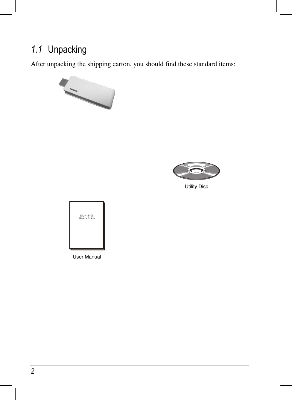
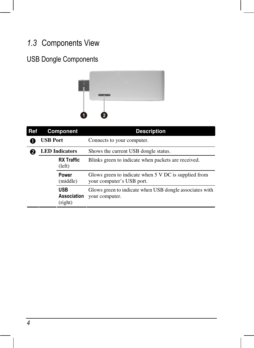
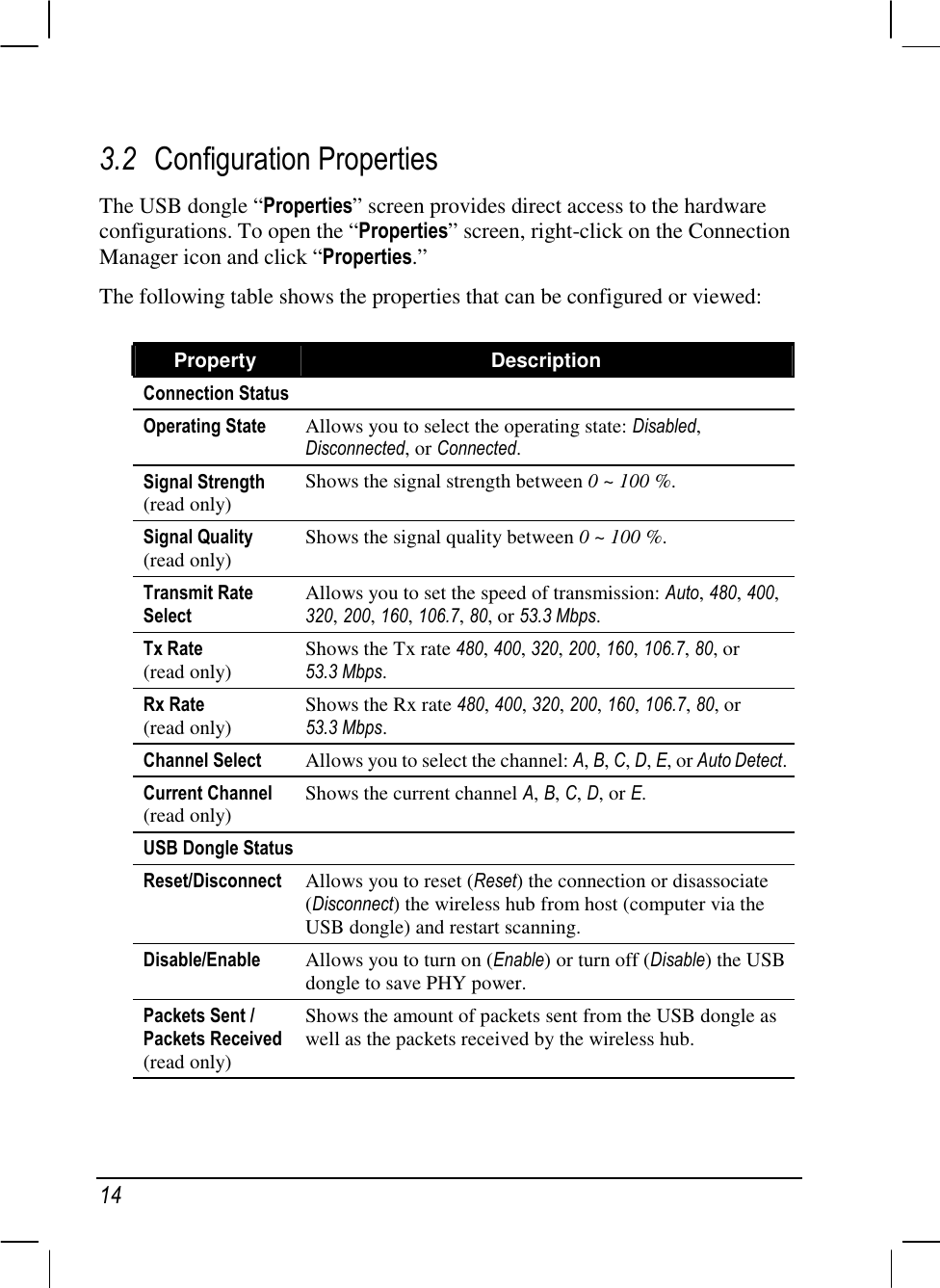
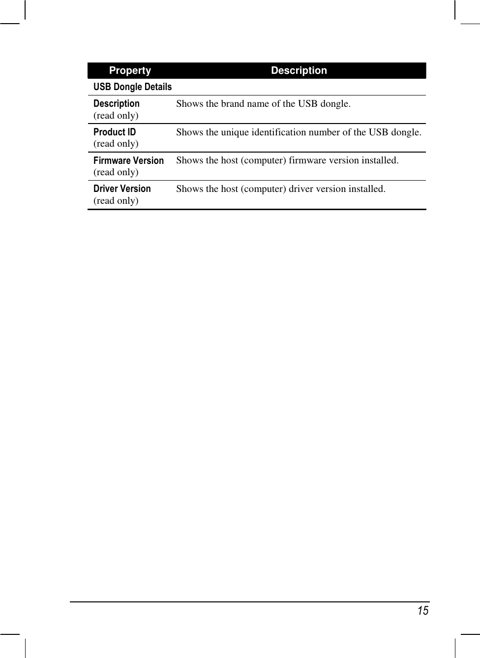
User Manual
Discussion / Help
Navigation