Mitac Digital Technology MUD-100 WIRELESS USB DONGLE User Manual MUD 100 user s manual rev2021407for ADT
Mitac International Corporation WIRELESS USB DONGLE MUD 100 user s manual rev2021407for ADT
User manual rev4

MUD-100 / MiTAC
MUD-100
User’s Guide
P/N : 5615 7608 0001
November 2006

TRADEMARKS
All brand, product names, and intellectual property rights are trademarks or
registered trademarks of their respective companies.
NOTE
The information in this manual is subject to change without notice.

i
Regulatory Information
NOTE: Marking labels located on the exterior of your device indicate the regulations that
your model complies with.
Federal Communication Commission
Interference Statement
This equipment has been tested and found to comply with the limits for
a Class B digital device, pursuant to Part 15 of the FCC Rules. These
limits are designed to provide reasonable protection against harmful
interference in a residential installation. This equipment generates, uses
and can radiate radio frequency energy and, if not installed and used in
accordance with the instructions, may cause harmful interference to
radio communications. However, there is no guarantee that
interference will not occur in a particular installation. If this equipment
does cause harmful interference to radio or television reception, which
can be determined by turning the equipment off and on, the user is
encouraged to try to correct the interference by one of the following
measures:
- Reorient or relocate the receiving antenna.
- Increase the separation between the equipment and receiver.
- Connect the equipment into an outlet on a circuit different from
that to which the receiver is connected.
- Consult the dealer or an experienced radio/TV technician for
help.
This device complies with Part 15 of the FCC Rules. Operation is
subject to the following two conditions: (1) This device may not cause
harmful interference, and (2) this device must accept any interference
received, including interference that may cause undesired operation.
FCC Caution: Any changes or modifications not expressly approved by
the party responsible for compliance could void the user's authority to
operate this equipment.

IMPORTANT NOTE:
FCC Radiation Exposure Statement:
This equipment complies with FCC radiation exposure limits set forth for an
uncontrolled environment. End users must follow the user's manual operating
instructions for satisfying RF exposure compliance.
This transmitter must not be co-located or operating in conjunction with any
other antenna or transmitter.
NOTE:
A UWB device operating under the provisions of this section shall transmit only
when it is sending information to an associated receiver. The UWB intentional
radiator shall cease transmission within 10 seconds unless it receives an
acknowledgement from the associated receiver that its transmission is being
received. An acknowledgment of reception must continue to be received by the
UWB intentional radiator at least every 10 seconds or the UWB device must
cease transmitting.
Per FCC regulations, an intentional radiator may only transmit when
communicating with an associated receiver. This continuous transmit mode is
for evaluation purposes only.
In end-user applications, this is handled through handshaking,
acknowledgements, negotiation of the communication channel, and other
mechanisms that ensure the transmitter is active when communicating with a
receiver.

iii
Safety Information
Only qualified persons are authorized to carry out maintenance on this device.
Read this User Manual carefully and follow the correct procedure when
setting up the device.
Do not open or attempt to disassemble or modify the device. Never insert
any metallic object into the device to avoid any risk of electric shock, fire,
short-circuiting or dangerous emissions. The device contains no
user-serviceable parts. If it appears to be malfunctioning, have it inspected
by a qualified technical support representative.
Never expose your device to rain, or use it near water, or in damp or wet
conditions. Never place objects containing liquids on your device, as they
may spill into its openings. Doing so increases the risk of electrical shock,
short-circuiting, fire or personal injury.
Do not expose the device beyond 50
o
C degree. Doing so may damage the
device or disfigure its casing. Avoid placing your device near a source of
heat or exposing it to sunlight (even through a window). Inversely, placing
your device in an environment that is too cold may damage the unit.
Always unplug the device from the electrical outlet if there is a risk of
lightning or if it will be unused for an extended period of time. Otherwise,
there is an increased risk of electrical shock, short-circuiting or fire.
Use only the power supply shipped with the device.
Do not use the device near other electrical appliances such as televisions,
radios or speakers. Doing so may cause interference which will adversely
affect the operation of the other products.
Do not place the device near sources of magnetic interference, such as
computer displays, televisions or speakers. Magnetic interference can affect
the operation and stability of your device.
Do not place heavy objects on top of the device or use excessive force on it.
Protect your device from excessive exposure to dust during use or storage.
Dust can build up inside the device, increasing the risk of damage or
malfunction.

Never use benzene, paint thinners, detergent or other chemical products to
clean the outside of the device. Such products will disfigure and discolor the
casing. Instead, use a soft dry cloth to wipe the device.

v
Table of Contents
Regulatory Information..........................................................................i
Safety Information...............................................................................iii
Chapter 1
Introduction..................................................................... 1
1.1
Unpacking .....................................................................................2
1.2
Specifications ................................................................................3
1.3
Components View.........................................................................4
USB Dongle Components.............................................................4
Chapter 2
Setting Up........................................................................ 5
Step 1. Install the Software Application and Driver...............................5
Step 2. Install the USB Dongle .............................................................6
Chapter 3
Using the USB Dongle and Wireless Hub........................... 11
3.1
Making the Connection ...............................................................12
3.2
Configuration Properties .............................................................14
Limited Warranty.............................................................................. 17

1
Chapter 1 Introduction
Your MUD-100 Wireless USB dongle allows you to connect to WUH-4100
Wireless USB Hub Wirelessly. By using Wireless USB dongle and Hub kit,
you can set up an ad hoc, wireless network instantly, extending USB range
without the hassle of setting up a network infrastructure; thereby providing a
right balance between functionality and design. It allows remote content
browsing, sharing, control, multi-channel streaming, hotsync, printing, fast
copy and very fast exchange of information between PC and USB 2.0/1.1 PC
peripherals. The types of content supported are data, applications, pictures, and
compressed video and audio files (asynchronous transfer).
Examples of USB PC peripherals (device side) types that can be used with your
USB cable replacement kit includes:
Wireless hub – multi-port wireless hub for legacy USB 2.0 / USB 1.1
devices
Combination of wireless hub and devices – wireless hub with: WLAN
access point/router/gateway, DSL modem/router, all-in-one memory card
reader, desktop DVD player, desktop hard disk drive
Wireless cradle – for digital still camera, cellular phones, smartphones,
PDA, MP3 players (such as iPod), camcorder, wireless (iPod) speakers.
laptop/notebook docking stations/port replicator
Wireless embedded PC peripheral devices – integrated into different
products such as wireless digital still camera, wireless portable hard disk
drives, wireless camcorder, wireless printer, wireless scanner, wireless
DVD player
2
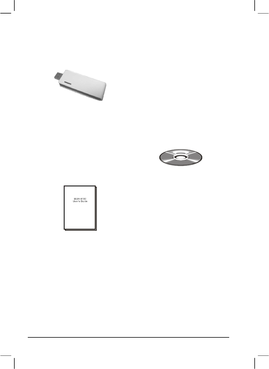
1.1 Unpacking
After unpacking the shipping carton, you should find these standard items:
Utility Disc
User Manual

3
1.2 Specifications
NOTE: Specifications are subject to change without notice.
Chipset
Wisair 531 MAC/BB chip + Wisair 502 RF chip
Operational Range
Up to 10 to 20 meters (30 to 60 feet)
PHY Data Rate
Up to 480 Mbps
(automatic or manually selected)
Frequency Range
3.1 ~ 4.8 GHz supporting 3 sub-bands,
528 MHz each
RF Modulation Type
Multiband OFDM
USB Version
USB 2.0/1.1
USB Power Drive
Powers up to 4 external USB devices
(500 mA at 5 VDC each)
USB Association Type
Host GUI-based association
Operating System
Microsoft® Windows XP SP2
Coexistence
• Standard WiMedia devices
• Co-located additional USB dongles or UWB
systems (FFI, TFI schemes)
Maximum Output Power
-34.72 dBm
Maximum Power Consumption
• For USB Dongle –
1.75 W (350 mA at 5 VDC from USB port)
Dimension (W×D)
• For USB Dongle –
25×69 mm
Environment
• Operating temperature:
5
0
C (41
0
F) to 50
0
C (122
0
F)
• Operating relative humidity:
10 % to 95 % non-condensing
Compliance
• WiMedia PHY spec. Rev. 1.0
• FCC
CFR 47 Part 15 subpart F; UWB
intentional radiation
4
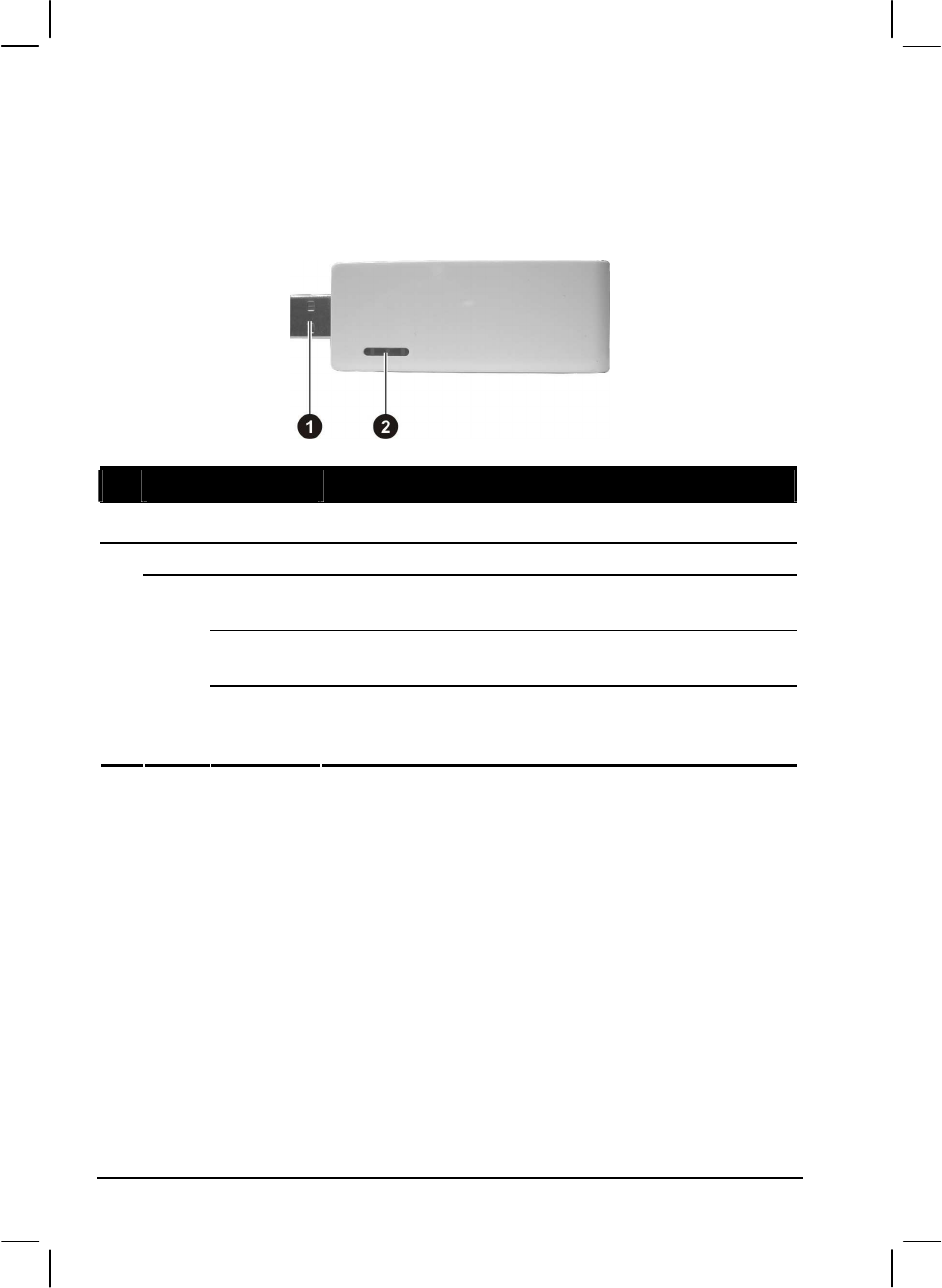
1.3 Components View
USB Dongle Components
Ref
Component Description
USB Port Connects to your computer.
LED Indicators Shows the current USB dongle status.
RX Traffic
(left)
Blinks green to indicate when packets are received.
Power
(middle)
Glows green to indicate when 5 V DC is supplied from
your computer’s USB port.
USB
Association
(right)
Glows green to indicate when USB dongle associates with
your computer.

5
Chapter 2 Setting Up
Minimum system requirements:
One available high speed USB 2.0 port
Windows XP with SP2
3 MB of free disk space
Step 1. Install the Software Application and Driver
NOTE: Do not attach the USB dongle to your computer and make sure that the wireless
hub is not connected to power at this point.
1. Insert the driver disc into the optical drive of your computer.
2. Run the “Setup_ver_xx_xx.exe” on the driver disc.
3. Follow the onscreen instructions and proceed by clicking “Next >” and
“continue anyway” when prompted.
4. When the installation procedure is successfully finished, proceed by
clicking “Finish” twice and restarting your computer.
6
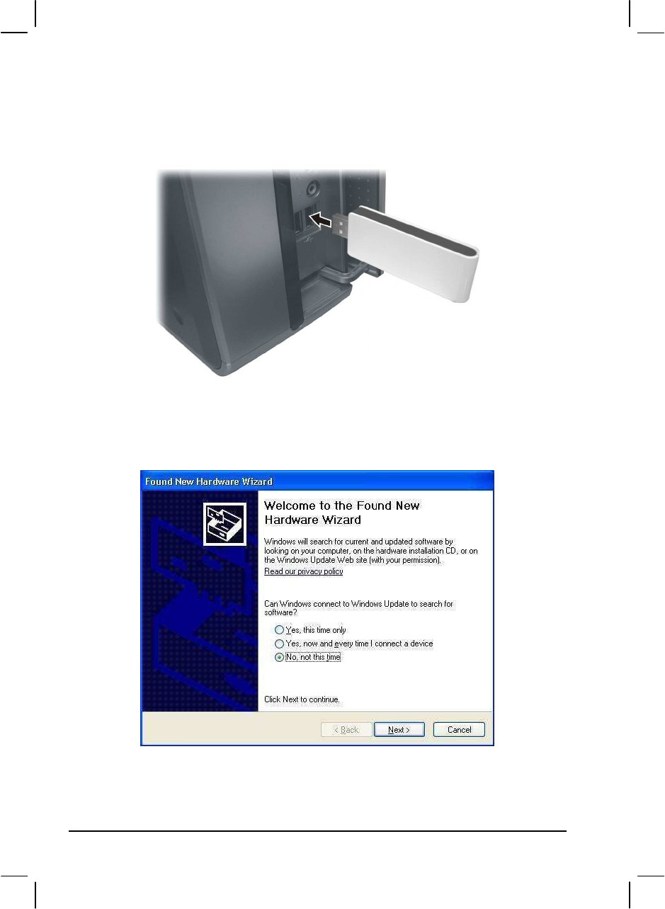
Step 2. Install the USB Dongle
1. Connect the USB dongle to your computer’s high speed USB port.
2. The system will automatically detect and begin installation of the driver for
the connected USB dongle using the “Found New Hardware Wizard.” Select
“No, not this time” and click “Next >.”
7
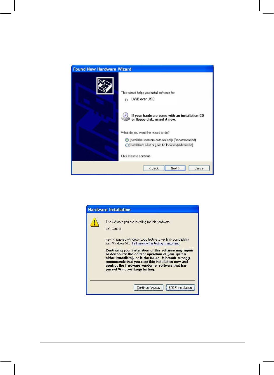
3. Select “Install the software automatically (Recommended)” and click
“Next >” to install the UWB over USB driver. The “Hardware Installation”
screen is displayed.
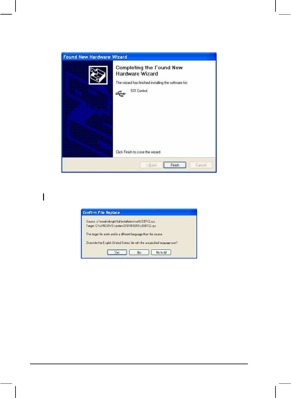
4. Click “Continue Anyway” and the “Completing the Found New Hardware
Wizard” screen is displayed.
8
5. Click “Finish” to complete the driver installation.
6. Windows will repeat this sequence for the UWB SW MAC driver.
NOTE: If during the installation the following screen is displayed, click “Yes.”
9
7. Disconnect the USB dongle from your computer’s USB port.
8. Restart your computer to ensure a successful USB driver installation.
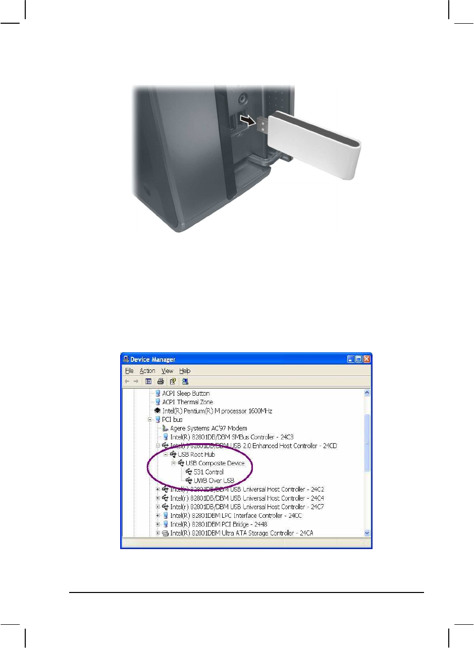
9. Connect the USB dongle to your computer’s USB port.
10. Verify a successful USB driver installation by running the Window’s
“Device Manager” utility (e.g., Start > Run > devmgmt.msc) and confirm that
it recognizes the USB dongle driver as shown in the following screen (select
View > by Connection).

10
11
Chapter 3 Using the USB Dongle and
Wireless Hub
After successfully installing the drivers for the USB dongle and wireless hub,
you can start communicating with other USB devices wirelessly. The
Connection Manager icon appears on your Windows system tray. The following
table shows the icon color and the corresponding activity status:
Please Note: In compliance with 47 CFR 15.519(a)(1) the wireless
dongle and /or hub will cease transmission within 10 seconds
unless it receives an acknowledgement from the other that its
transmission is being received. An acknowledgment of reception
must continue to be received by the wireless dongle and / or hub at
least every 10 seconds or the UWB device will cease transmitting
until it receives acknowledgement. This may cause some
additional delay in operation when first associating the dongle and
hub if hub is out of range of dongle or power is applied to hub after
10 seconds of dongle connection.
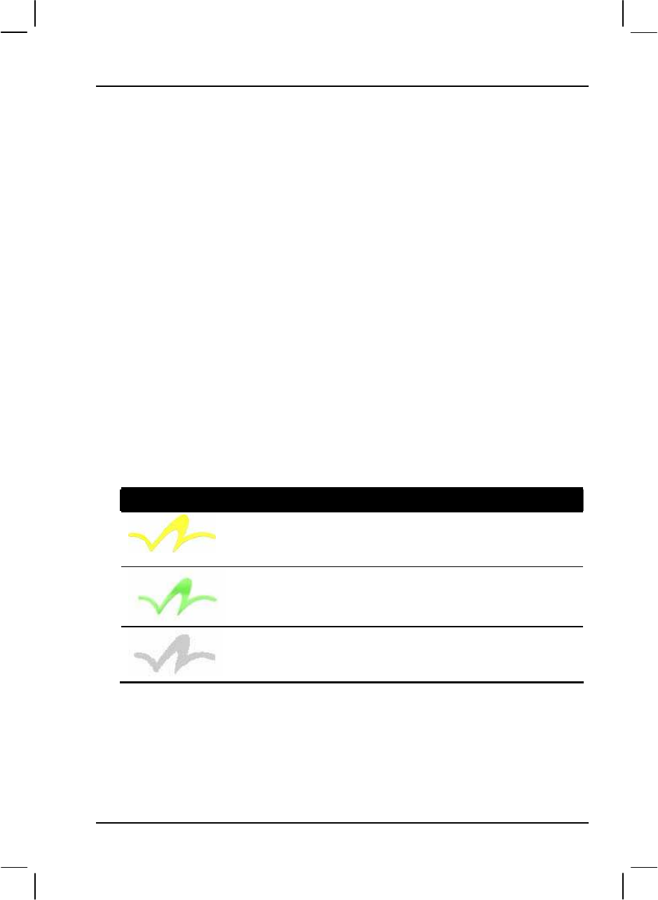
Icon Color Status
Enabled (yellow icon)
The USB dongle is connected to the computer and enabled
but no wireless connection is detected.
Connected (green icon)
The USB dongle is connected to the computer, is enabled,
and is associated with the wireless hub.
Disabled (gray icon)
The USB dongle is not connected to the computer or, is
connected to the computer but is disabled.
12
3.1 Making the Connection
To start using the USB dongle and wireless hub:
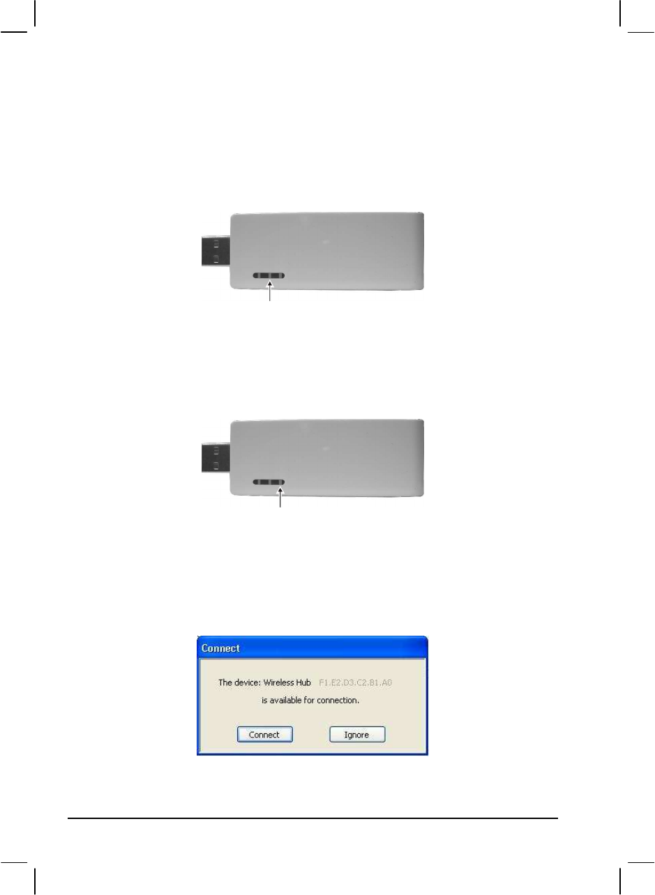
1. Connect the USB dongle to the USB port of your computer and the power
LED lights up.
The USB dongle which has a unique host ID pre-configured (a product ID
that resembles the MAC address format) will start scanning the airwaves for
first available channel. After a few seconds when the computer to USB
association is formed, the USB association LED lights up.
2. Connect the wireless hub to power. The wireless hub will start locating a
wireless host by scanning for available channels.
3. The wireless hub will start to request association with your computer via the
USB dongle and the association authorization screen is displayed.
USB Association
Power

13
Approve the association by clicking “Connect” and the wireless hub will
switch to the Connected state.
NOTE:
The association authorization screen is only displayed the first time the wireless hub is
requesting association with your computer. The next time you use the same wireless
hub it will be automatically associated.
The wireless hub’s product ID is displayed in order to identify which wireless hub is
requesting the connection. This is important when more than one active wireless hub is
within range. To connect to a different wireless hub, click “Ignore” and wait for a few
seconds for another wireless hub to request the connection.
4. Connect USB device(s) to the wireless hub and bi-directional data transfer
can begin between your computer and devices connected to the wireless
hub.
14
3.2 Configuration Properties
The USB dongle “Properties” screen provides direct access to the hardware
configurations. To open the “Properties” screen, right-click on the Connection
Manager icon and click “Properties.”
The following table shows the properties that can be configured or viewed:
Property Description
Connection Status
Operating State Allows you to select the operating state: Disabled,
Disconnected, or Connected.
Signal Strength
(read only)
Shows the signal strength between 0 ~ 100 %.
Signal Quality
(read only)
Shows the signal quality between 0 ~ 100 %.
Transmit Rate
Select
Allows you to set the speed of transmission: Auto, 480, 400,
320, 200, 160, 106.7, 80, or 53.3 Mbps.
Tx Rate
(read only)
Shows the Tx rate 480, 400, 320, 200, 160, 106.7, 80, or
53.3 Mbps.
Rx Rate
(read only)
Shows the Rx rate 480, 400, 320, 200, 160, 106.7, 80, or
53.3 Mbps.
Channel Select Allows you to select the channel: A, B, C, D, E, or Auto Detect.
Current Channel
(read only)
Shows the current channel A, B, C, D, or E.
USB Dongle Status
Reset/Disconnect
Allows you to reset (Reset) the connection or disassociate
(Disconnect) the wireless hub from host (computer via the
USB dongle) and restart scanning.
Disable/Enable Allows you to turn on (Enable) or turn off (Disable) the USB
dongle to save PHY power.
Packets Sent /
Packets Received
(read only)
Shows the amount of packets sent from the USB dongle as
well as the packets received by the wireless hub.

15
Property Description
USB Dongle Details
Description
(read only)
Shows the brand name of the USB dongle.
Product ID
(read only)
Shows the unique identification number of the USB dongle.
Firmware Version
(read only)
Shows the host (computer) firmware version installed.
Driver Version
(read only)
Shows the host (computer) driver version installed.

17
Limited Warranty
In no event shall the liability of MiTAC International Corp. (MiTAC)
exceed the price paid for the product from direct, indirect, special,
incidental, or consequential software, or its documentation.
MiTAC offers no refunds for its products.
MiTAC makes no warranty or representation, expressed, implied, or
statutory, with respect to its products or the contents or use of this
documentation and all accompanying software, and specifically disclaims
its quality, performance, merchantability, or fitness for any particular
purpose.
MiTAC reserves the right to revise or update its products, software, or
documentation without obligation to notify any individual or entity.