Mitel Networks 69134000 Aastra Access Point RFP34 US User Manual ommsip installation 1
Mitel Networks Aastra Access Point RFP34 US ommsip installation 1
UserManual.wiki
>
Mitel Networks
>
69134000 User Manual
users manual
Navigation menu
Upload a User Manual
Namespaces
Wiki Guide
HTML
PDF
Info
Views
User Manual
Discussion / Help
Navigation
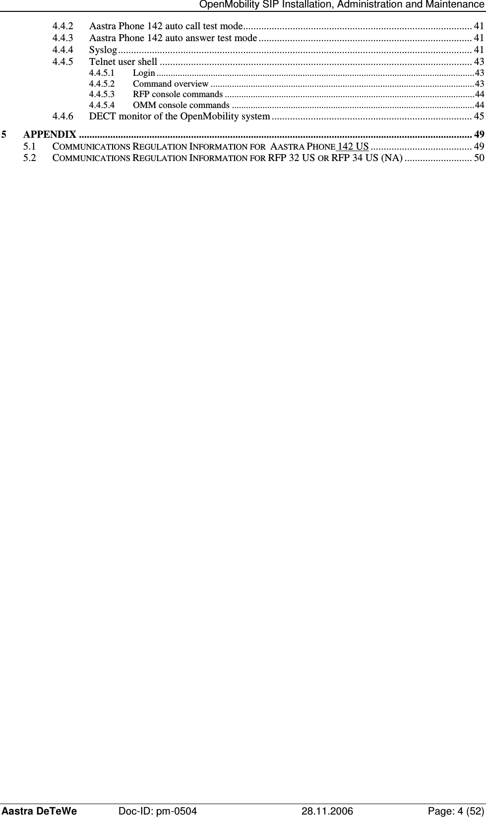
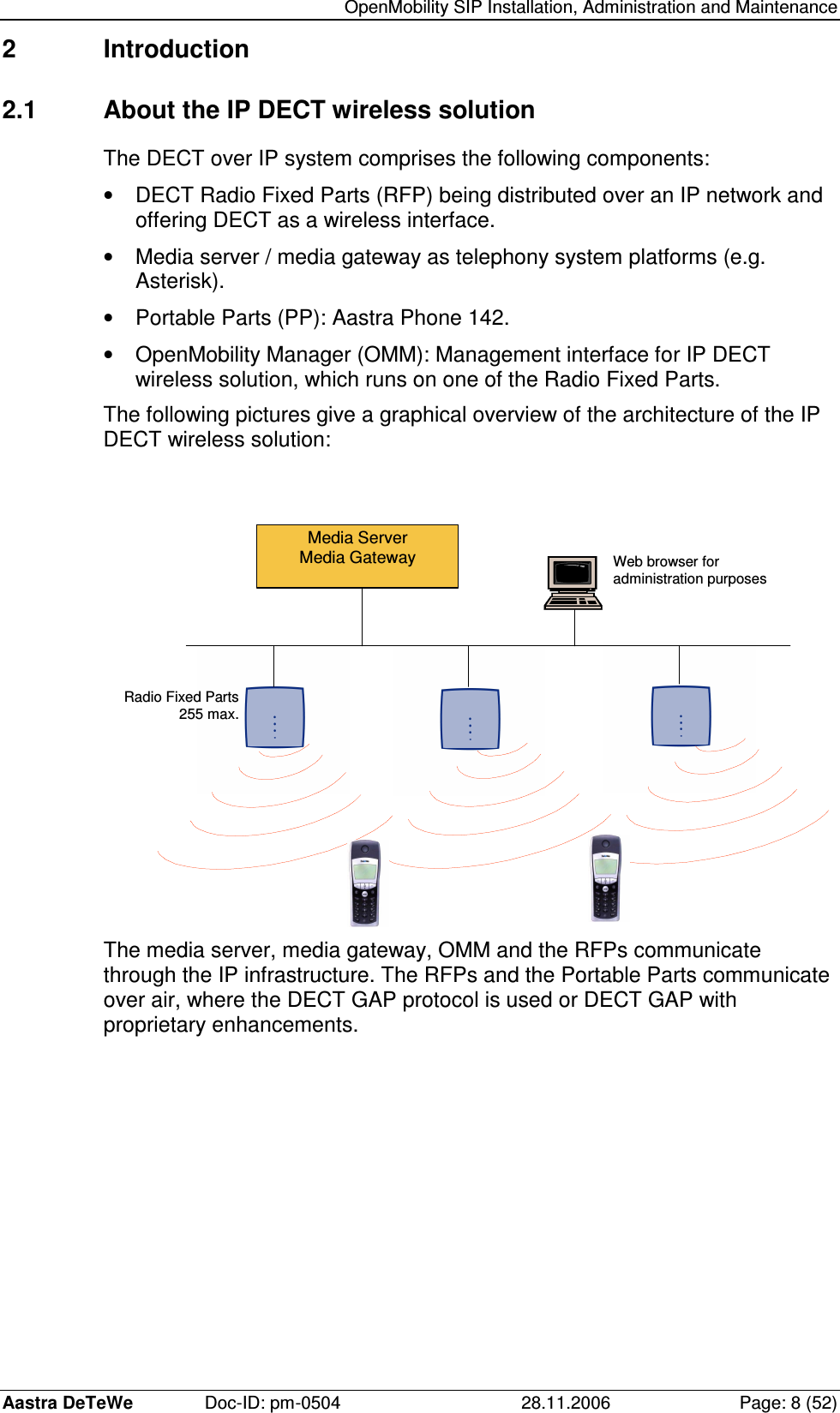
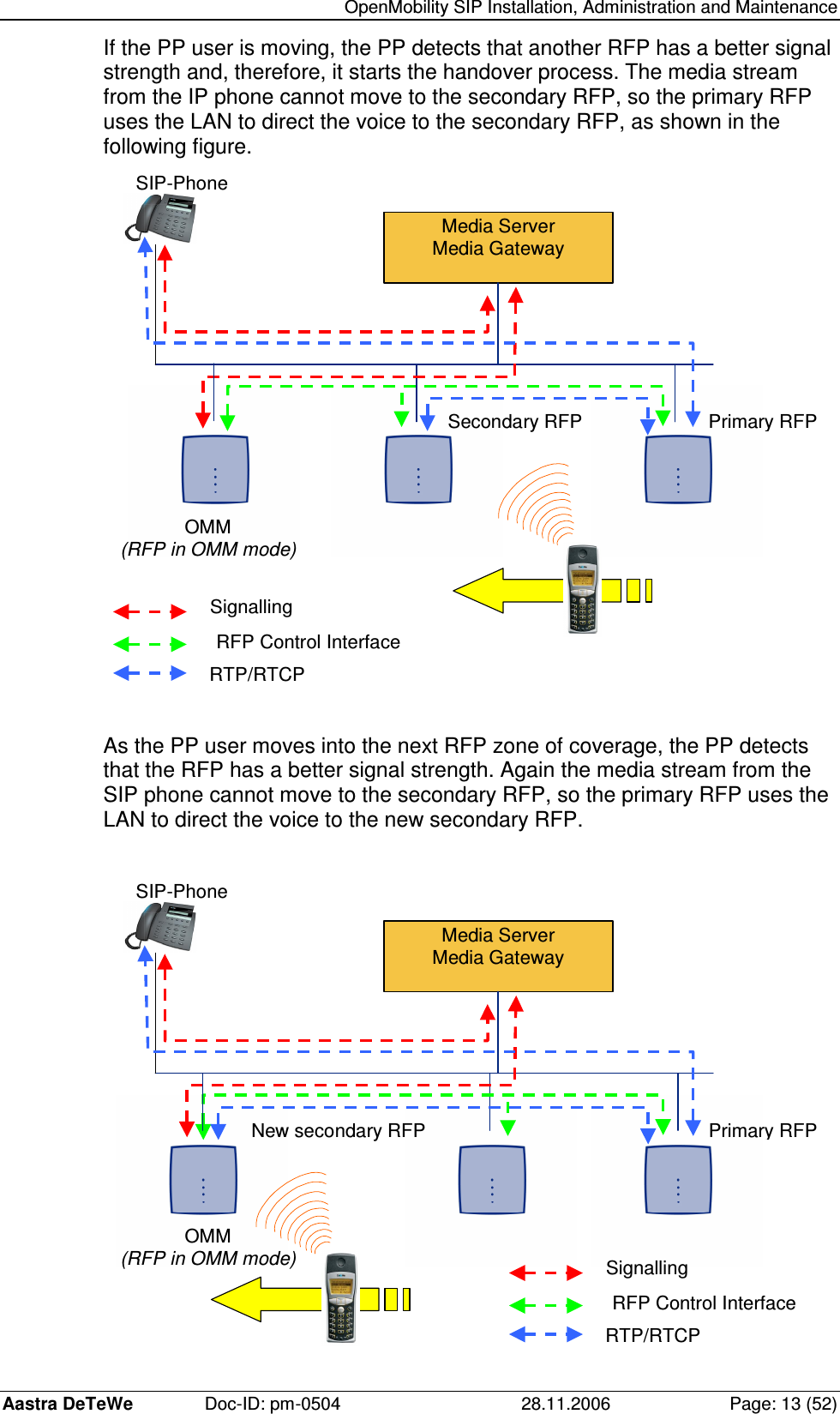
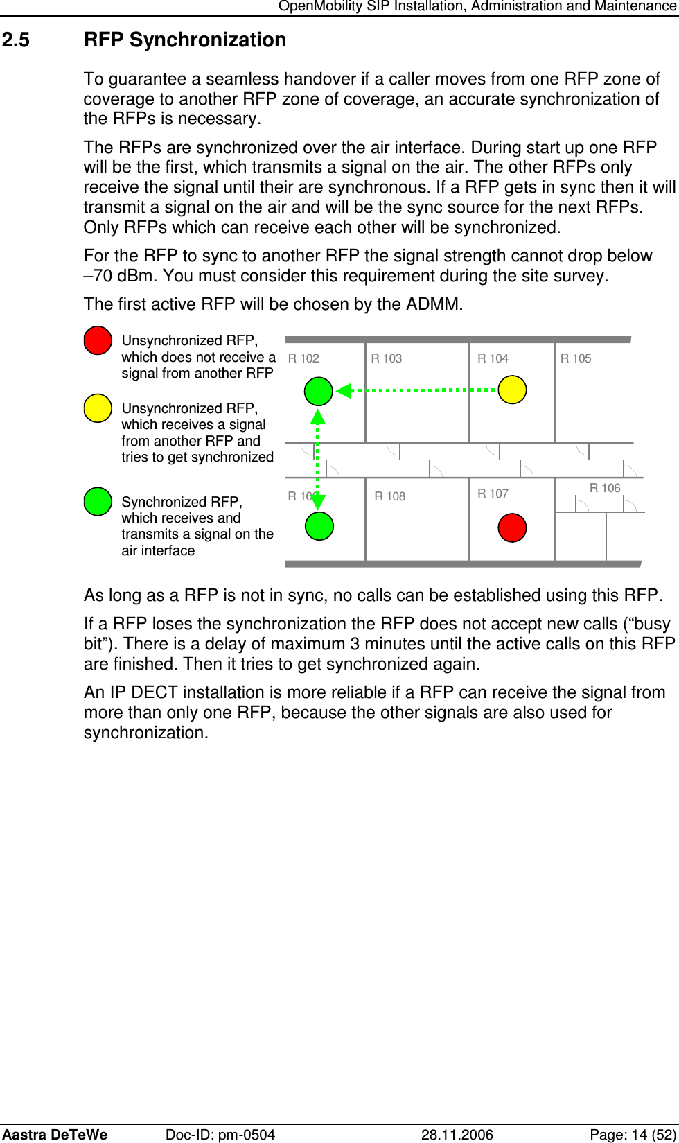
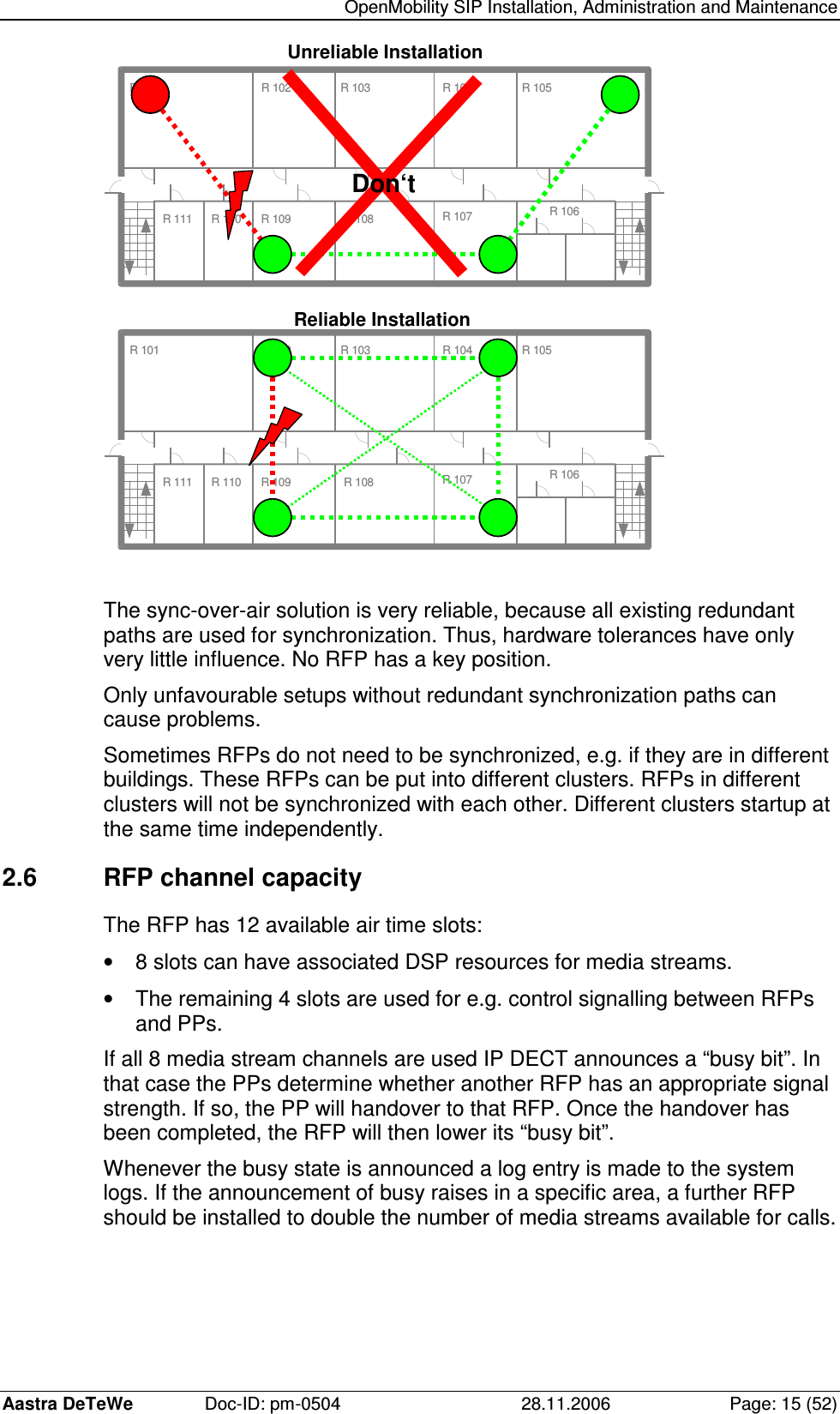
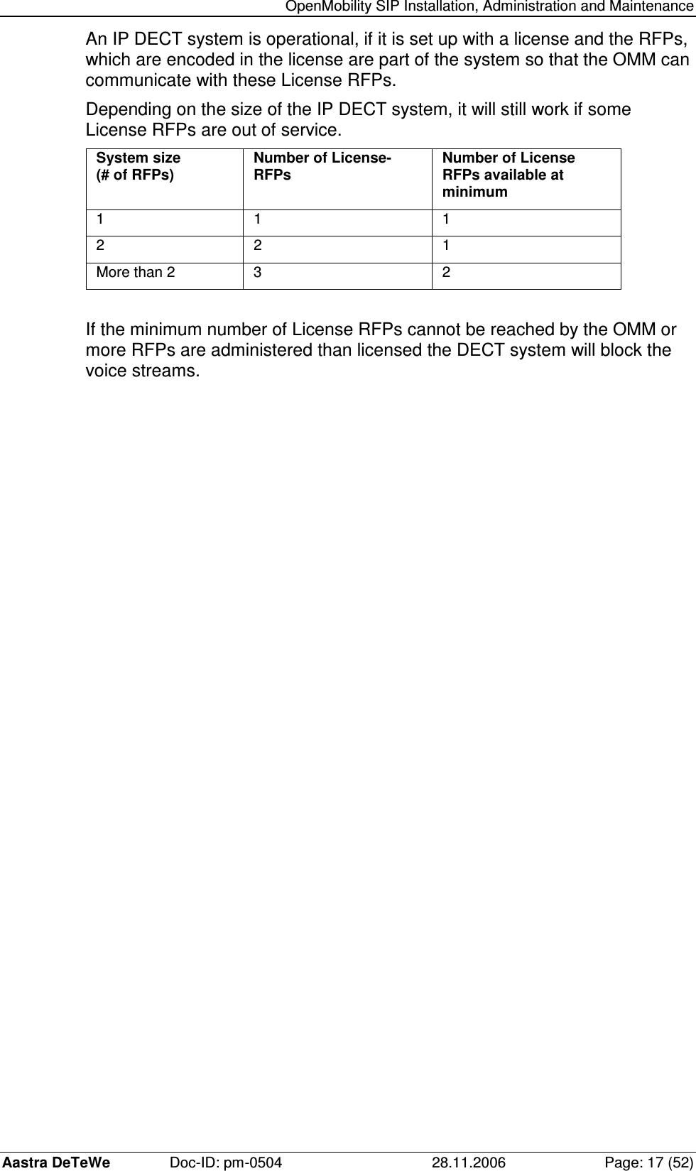
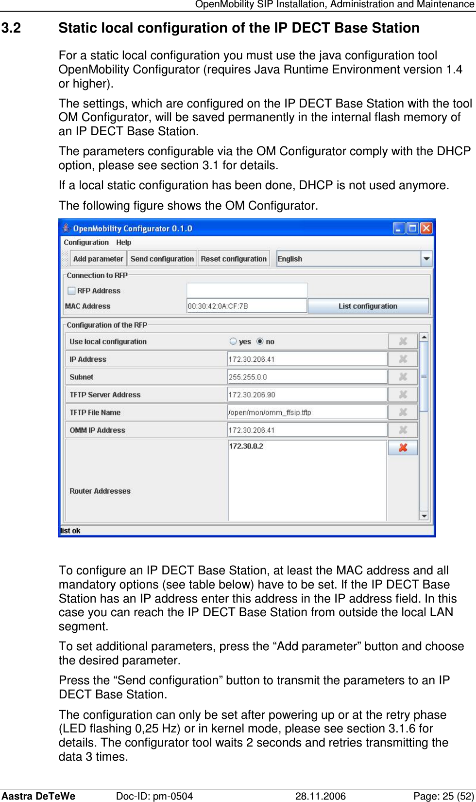
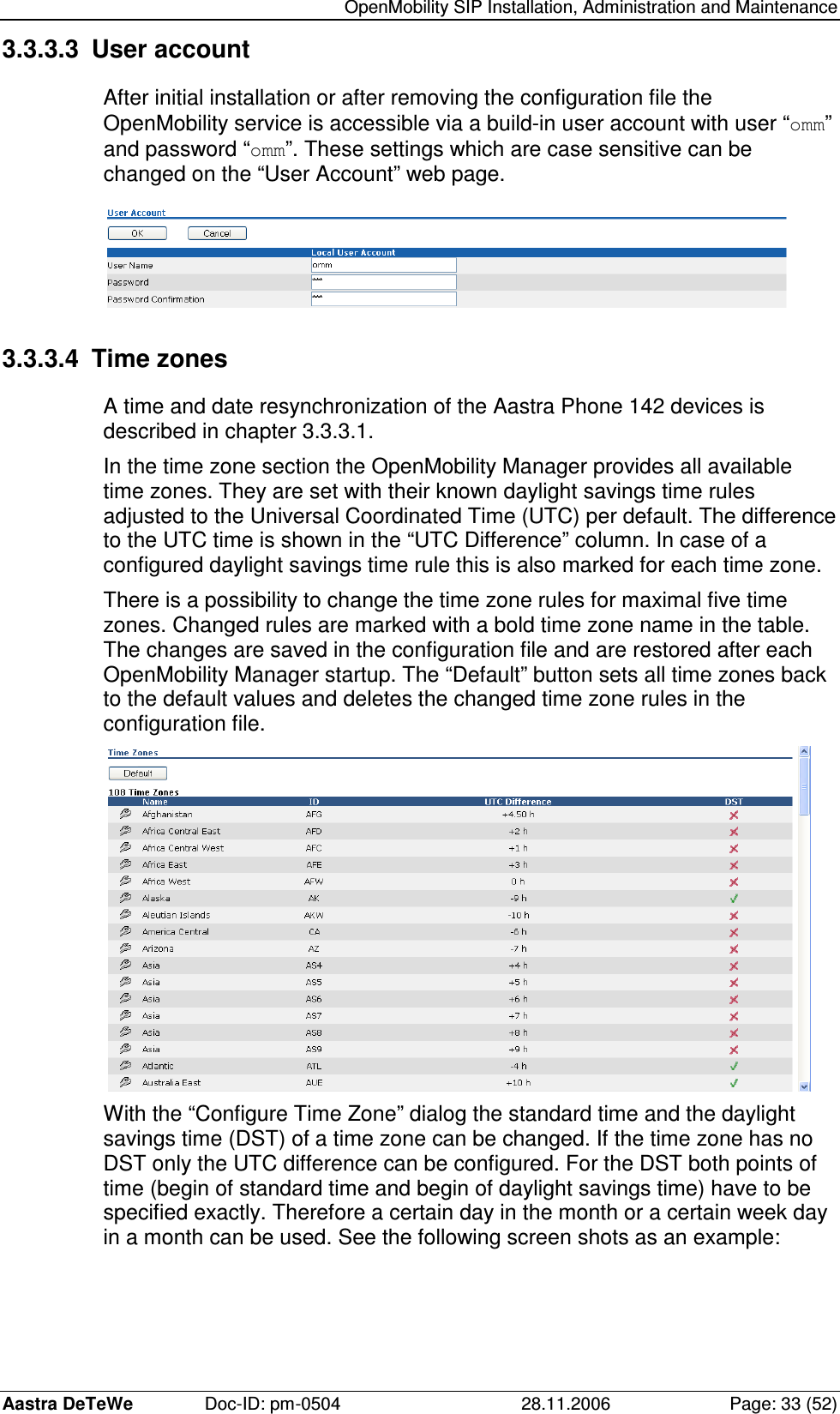

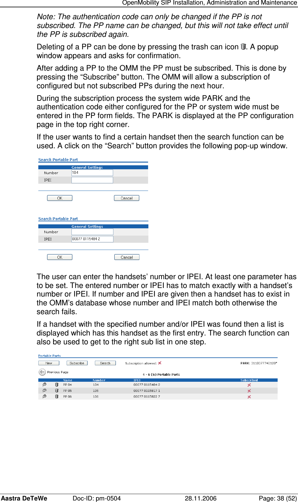
![OpenMobility SIP Installation, Administration and Maintenance Aastra DeTeWe Doc-ID: pm-0504 28.11.2006 Page: 44 (52) 4.4.5.3 RFP console commands If you type ip_rfpconsole you are able to use the following commands on each RFP: IP RFP console commands: heap - shows heap buffer statistics help - Displays Command Help Table lec - adjust linear echo canceler parameters media - display state of media channels mutex - lists all created MXP mutexes queues - lists all created MXP queues reset - resets the IPRFP application rsx - allows RSX connection to BMC via TCP sem - lists all created MXP semaphores spy - set/display spy levels: [ <key #> <level #> ] tasks - lists all running MXP tasks voice - displays the state of voice handling exit - leave the RFP console Note: The spy command enables you to increase the level of syslog messages. These should be used only by trained support personnel, because the spy command can harm the systems operation. 4.4.5.4 OMM console commands If you type ommconsole and you have opened the session on the OMM RFP you are able to use the following OMM related commands: Note: The spy command enables you to increase the level of syslog messages especially for subsystems of the OMM. These should be used only by trained support personnel, because the spy command can harm the systems operation.](https://usermanual.wiki/Mitel-Networks/69134000/User-Guide-796892-Page-44.png)