MitraStar Technology DSL2401HN2E1C VDSL VOIP User Manual
MitraStar Technology Corporation VDSL VOIP
UserManual.wiki
>
MitraStar Technology
>
DSL2401HN2E1C User Manual
User Manual
Navigation menu
Upload a User Manual
Namespaces
Wiki Guide
HTML
PDF
Info
Views
User Manual
Discussion / Help
Navigation


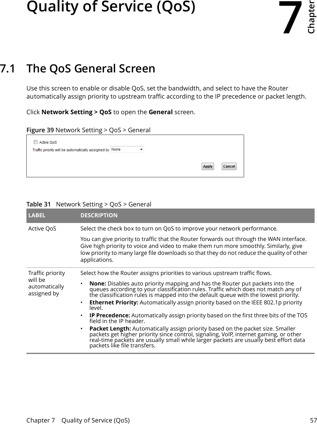
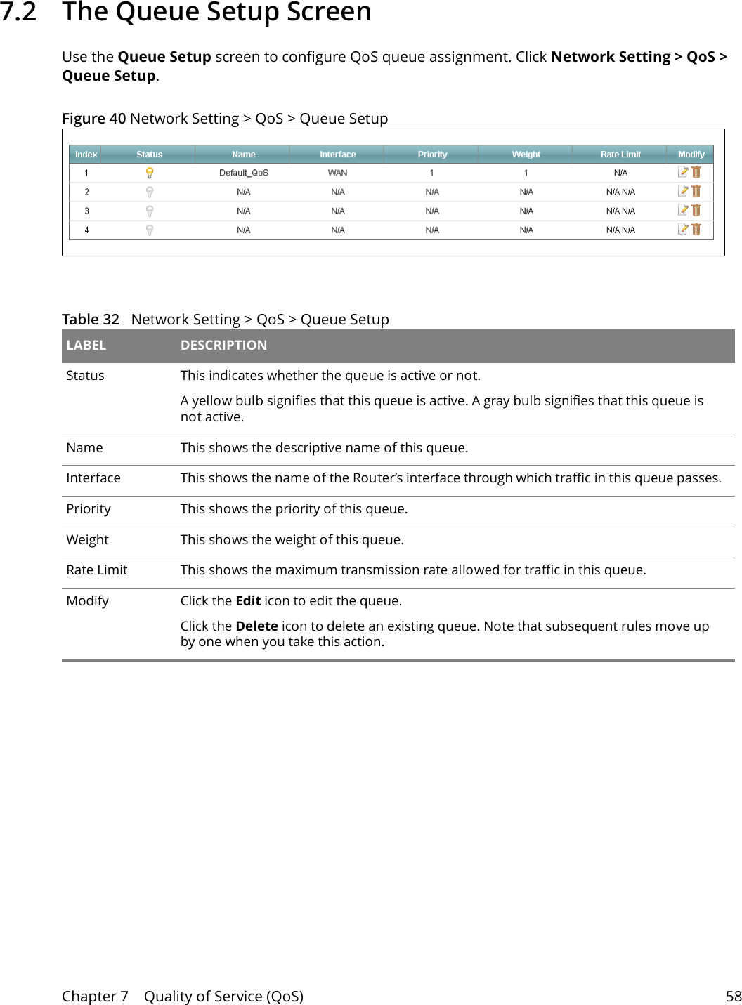
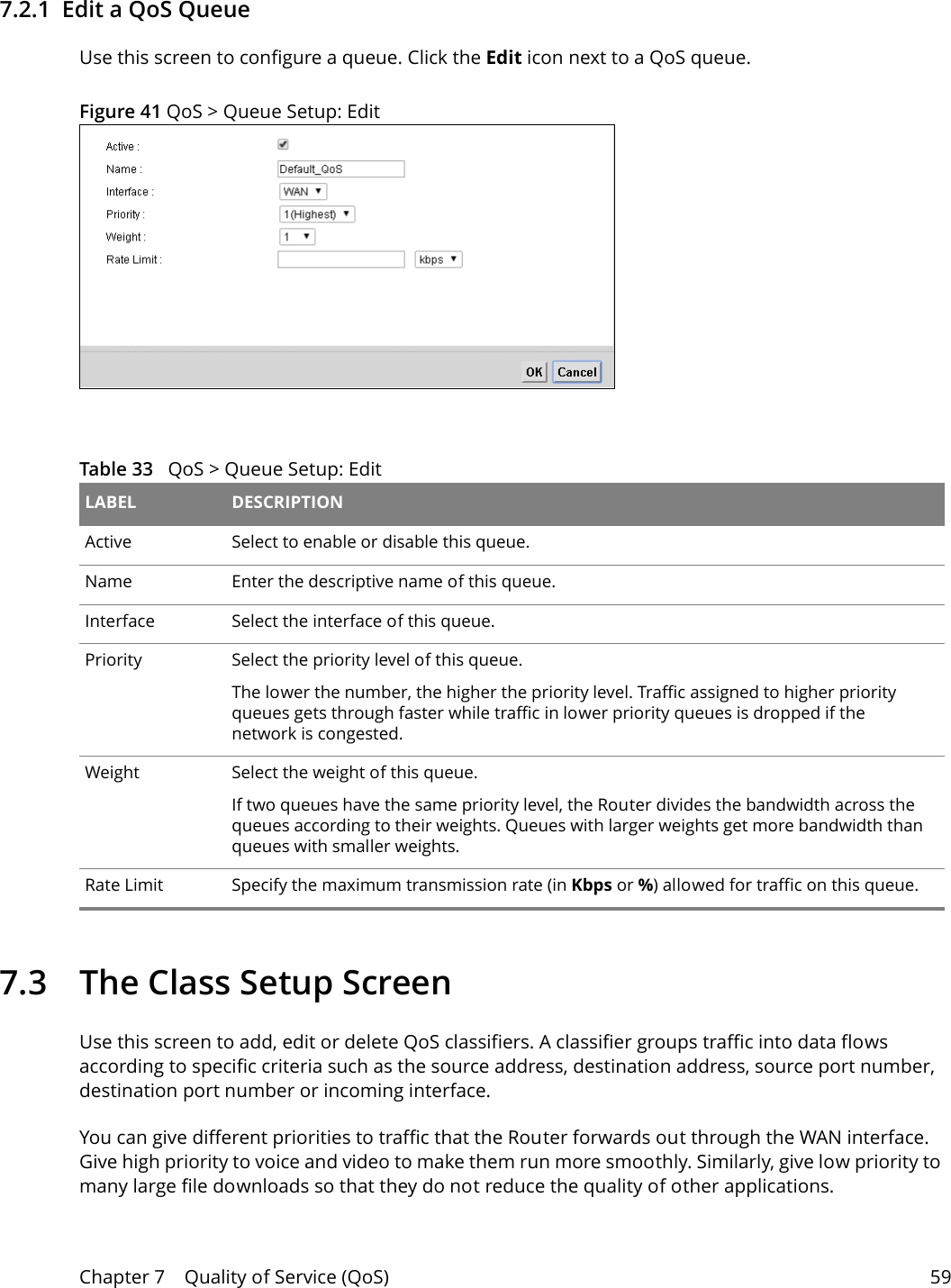
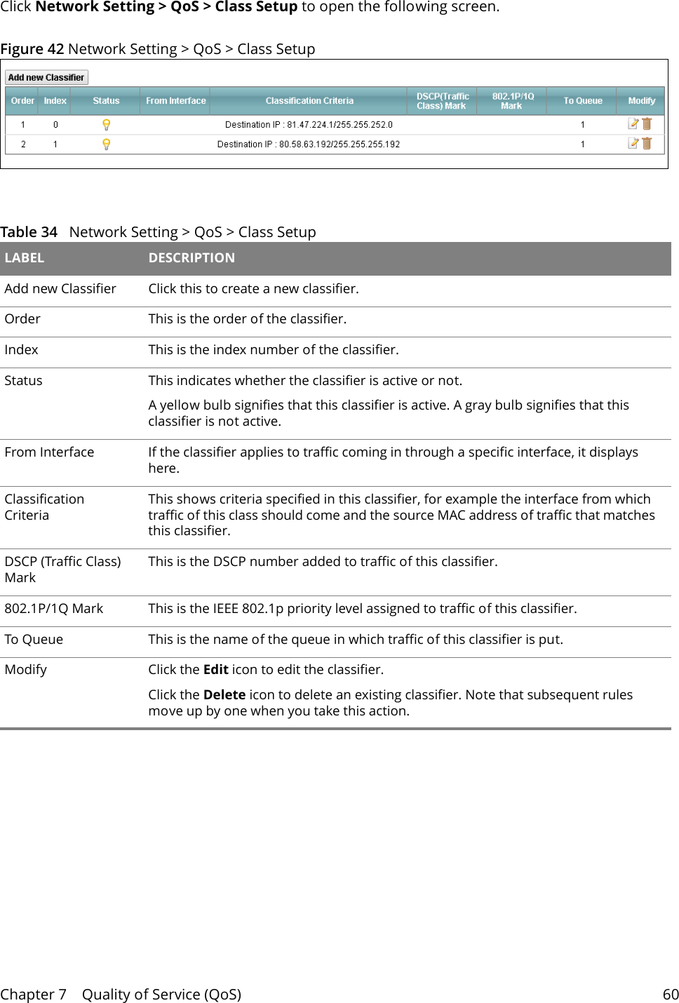
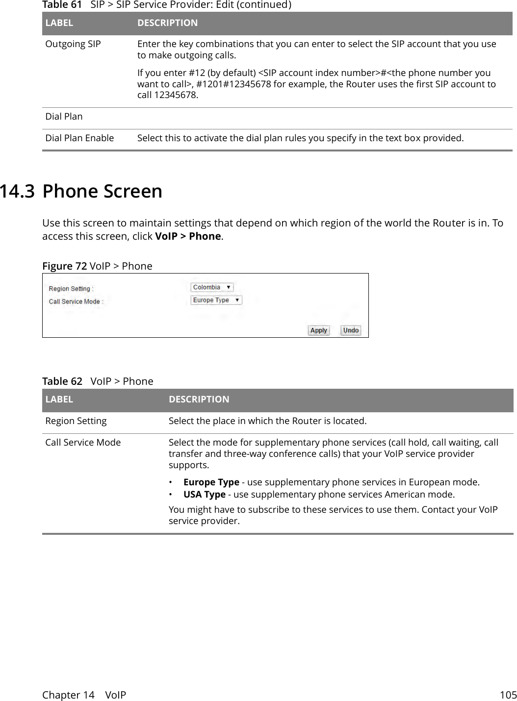
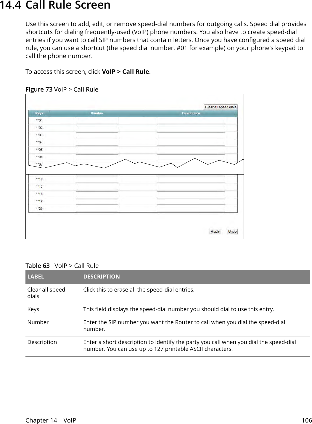
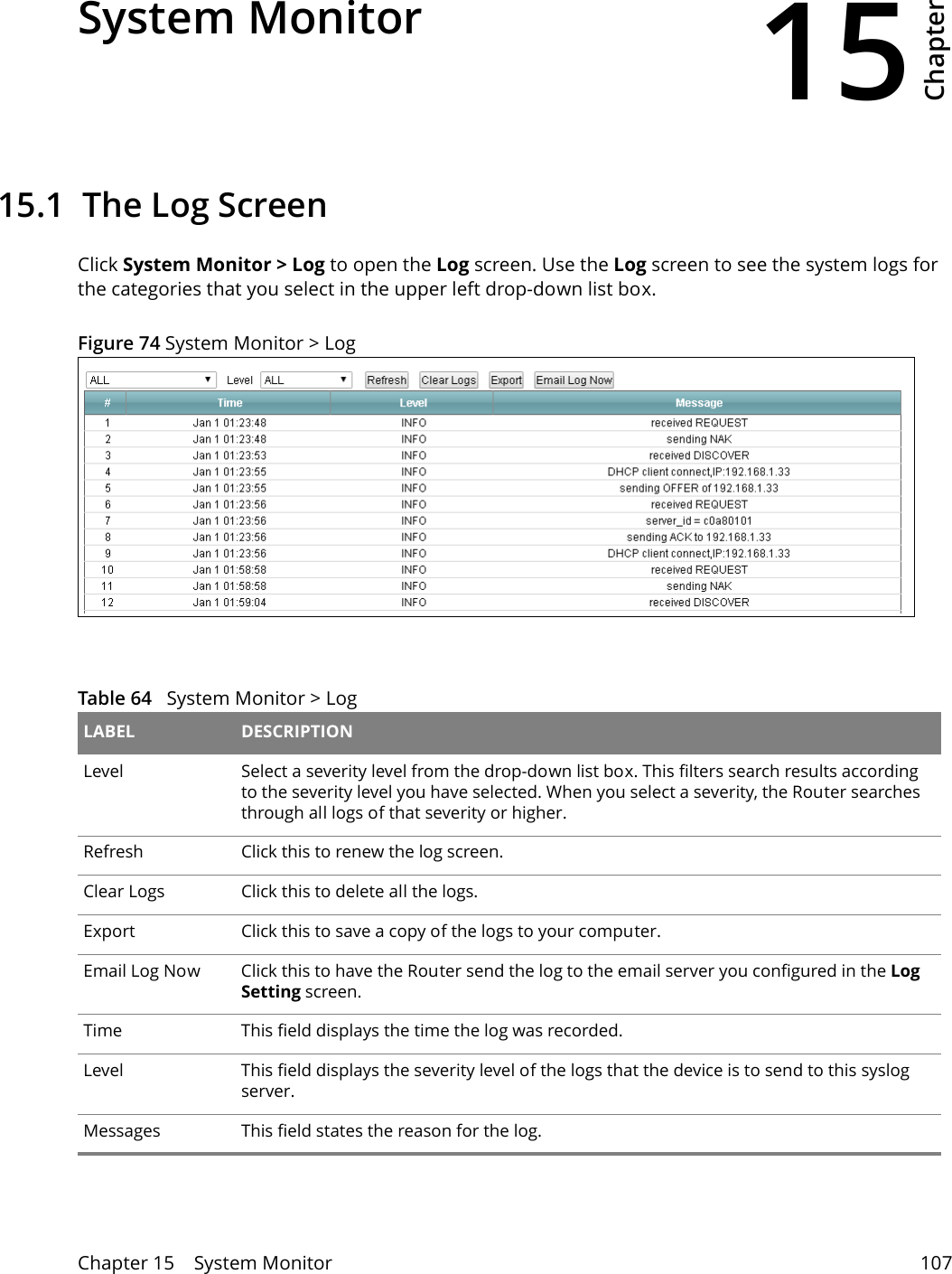
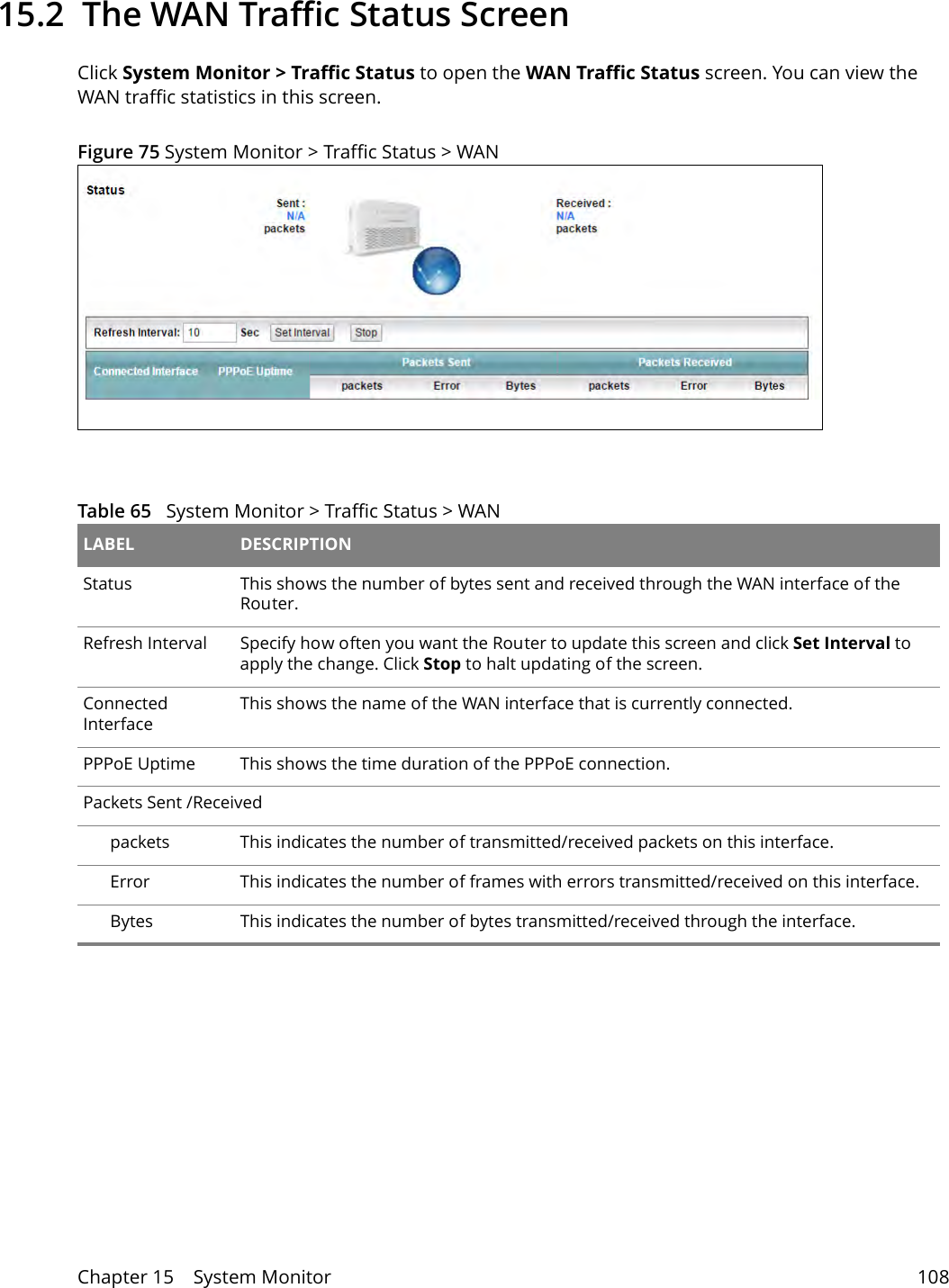
![Chapter 23 Troubleshooting 136Advanced Suggestions• Try to access the Router using another service, such as Telnet. If you can access the Router, check the remote management settings and firewall rules to find out why the Router does not respond to HTTP. • If your computer is connected wirelessly, use a computer that is connected to a LAN port. I can see the Login screen, but I cannot log in to the Router.1Make sure you have entered the user name and password correctly. These fields are case-sensitive, so make sure [Caps Lock] is not on. 2You cannot log in to the web configurator while someone is using Telnet to access the Router. Log out of the Router in the other session, or ask the person who is logged in to log out. 3Turn the Router off and on. 4If this does not work, you have to reset the device to its factory defaults. See Section 23.2 on page 134. I cannot Telnet to the Router. See the troubleshooting suggestions for I cannot see or access the Login screen in the web configurator. Ignore the suggestions about your browser. I cannot use FTP to upload / download the configuration file. / I cannot use FTP to upload new firmware.See the troubleshooting suggestions for I cannot see or access the Login screen in the web configurator. Ignore the suggestions about your browser.23.4 Internet Access I cannot access the Internet.1Check the hardware connections, and make sure the LEDs are behaving as expected. See Section 1.3 on page 9. 2Make sure you entered your ISP account information correctly. These fields are case-sensitive, so make sure [Caps Lock] is not on. 3If you are trying to access the Internet wirelessly, make sure the wireless settings in the wireless client are the same as the settings in the AP.](https://usermanual.wiki/MitraStar-Technology/DSL2401HN2E1C/User-Guide-3348878-Page-136.png)