MitraStar Technology DSL2401HN2E1C VDSL VOIP User Manual
MitraStar Technology Corporation VDSL VOIP
User Manual

1st Edition, Mar ,2017
DSL-2401HN2-E1C
User’s Guide
IMPORTANT!
READ CAREFULLY BEFORE USE.
KEEP THIS GUIDE FOR FUTURE REFERENCE.
Graphics in this book may differ slightly from the product due to differences in operating systems,
operating system versions, or if you installed updated firmware/software for your device. Every
effort has been made to ensure that the information in this manual is accurate.
Contents 3
Contents
7 Chapter 1: Introduction
7Overview
7 Hardware Connection
9 LEDs (Lights)
11 Chapter 2: Introducing the Web Configurator
11 Overview
11 Accessing the Web Configurator
12 The Network Map Screen
14 The Status Screen
15 The Web Configurator Layout
15 Title Bar
15 Main Window
17 Chapter 3: WAN
17 The WAN Screen
19 Edit ADSL Ethernet Connection
24 Edit VDSL Ethernet Connection
28 Chapter 4: Wireless 2.4GHz
28 Wireless General Screen
30 No Security
31 Basic (WEP Encryption)
31 More Secure (WPA2-PSK or WPA/WPA2 PSK mixed)
33 More AP Screen
34 Edit More AP
35 MAC Authentication Screen
36 The WPS Screen
38 The WDS Screen
39 The WMM Screen
40 Scheduling Screen
41 Add or Edit Schedule
42 Advanced Screen
43 Chapter 5: LAN
43 The LAN Setup Screen
45 The Static DHCP Screen
Contents 4
46 The IP Alias Screen
47 The UPnP Screen
48 The IPv6 LAN Setup Screen
52 Chapter 6: Static Route
52 Configuring Static Route
53 Add/Edit Static Route
53 IPv6 Static Route
54 Add/Edit IPv6 Static Route
55 The DNS Route Screen
55 Add/Edit DNS Route
56 The Current Route Screen
57 Chapter 7: Quality of Service (QoS)
57 The QoS General Screen
58 The Queue Setup Screen
59 Edit a QoS Queue
59 The Class Setup Screen
61 Add/Edit QoS Class
65 The QoS Monitor Screen
66 Chapter 8: Network Address Translation (NAT)
66 The General Screen
66 The Port Forwarding Screen
67 The Port Forwarding Screen
68 The Port Forwarding Add/Edit Screen
69 The Address Mapping Screen
70 The Address Mapping Rule Edit Screen
71 The DMZ Screen
71 The ALG Screen
73 Chapter 9: Dynamic DNS
73 The Dynamic DNS Screen
75 Chapter 10: Filter
75 The IP/MAC Filter Screen
77 The IPv6/MAC Filter Screen
79 Chapter 11: Firewall
79 Firewall General Screen
80 Add/Edit Interface Default Policy Screen
80 Rules Screen
83 Rules Edit Screen
Contents 5
84 DoS Screen
85 The DoS Advanced Screen
86 Chapter 12: Parental Control
86 The Parental Control Screen
88 Add/Edit a Parental Control Rule
90 Chapter 13: Certificates
90 Local Certificates
91 Trusted CA
92 Trusted CA Import
93 View Certificate
95 Chapter 14: VoIP
95 The SIP Account Screen
96 Edit SIP Account
99 The SIP Service Provider Screen
100 Edit SIP Service Provider
105 Phone Screen
106 Call Rule Screen
107 Chapter 15: System Monitor
107 The Log Screen
108 The WAN Traffic Status Screen
109 The LAN Traffic Status Screen
110 The NAT Traffic Status Screen
111 The VoIP Status Screen
113 Chapter 16: User Account
113 Overview
113 The User Account Screen
114 Chapter 17: System
114 The System Screen
115 Chapter 18: Time Setting
115 The Time Setting Screen
117 Chapter 19: Log Setting
117 The Log Setting Screen
120 Chapter 20: Firmware Upgrade
120 The Firmware Upgrade Screen
Contents 6
122 Chapter 21: Backup/Restore
122 The Backup/Restore Screen
124 The Reboot Screen
125 Chapter 22: Remote Management
125 The General Screen
125 The WWW Screen
127 Telnet Screen
127 FTP Screen
129 SNMP Screen
130 DNS Screen
131 ICMP Screen
132 SSH/SCP/SFTP Screen
134 Chapter 23: Troubleshooting
134 Overview
134 Power, Hardware Connections, and LEDs
135 Router Access and Login
136 Internet Access
137 Wireless Internet Access
138 Phone Calls and VoIP
139 Appendix A: Safety Warnings
1
Chapter
Chapter 1 Introduction 7
CHAPTER 1
Chapter 1 Introduction
1.1 Overview
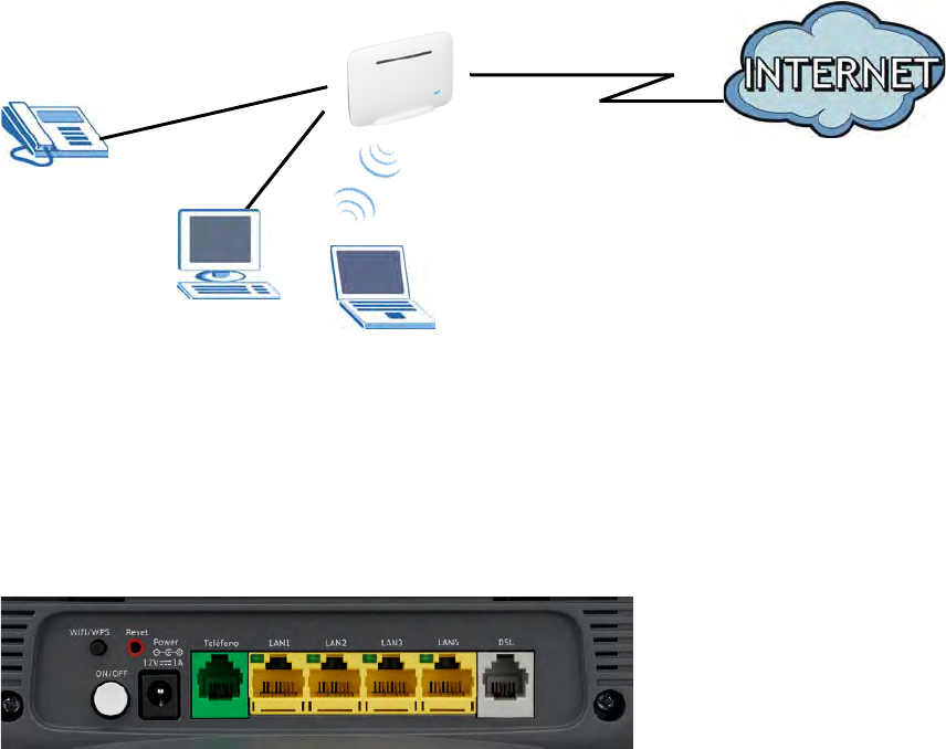
The DSL-2401HN2-E1C is a VDSL2 router with high-speed Internet access and wireless
networking capability. It has a phone port for making calls over the Internet (Voice over IP or
VoIP).
The following figure shows an application example of the Router:
The Router provides wired and wireless Internet access to home devices on the LAN as well as VoIP
service.
Figure 1 Application Example
VoIP Phone
DSL-2401HN2-E1C
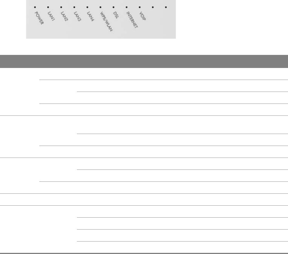
1.2 Hardware Connection
Make sure to use the proper cables and power adapter to connect the
Router.
Figure 2 The Rear Panel

Chapter 1 Introduction 8
The following table explains the connectors and buttons on the rear panel:
Table 1 The Rear Panel
CONECTOR DESCRIPTION
RESET Use this button to restore the default settings of the Router. Press this button for 5
seconds to restore default values. Press 1 second or longer to restart it.
Note: If you reset the Router, you will lose all configurations that you had previously
and the password will be reset to the defaults.
WPS/WLAN Use this button to enable or disable the WiFi and WPS features on the Router.
The WiFi feature is enabled by default. Press this button for 1 second to turn it off.
To enable the WPS feature, press the button for 5 seconds The WPS LED on the front
panel will flash yellow while the Router sets up a WPS connection with the wireless
device.
Note: To activate WPS, you must enable WPS in the Router and in another wireless
device within two minutes of each other.
ON/OFF Use this button to turn the Router on or off.
POWER Connect the provided power adapter to the 12V-1A power connector. Attach the
power adapter to a proper power source.
VOIP Use a telephone cable to connect the Router to a VoIP phone for VoIP service.
LAN4-1 Use an Ethernet cable to connect a computer to one of these ports for initial
configuration and/or Internet access.
DSL Use an RJ-11 telephone wire to connect this port to a telephone jack for VDSL WAN
access.
Chapter 1 Introduction 9
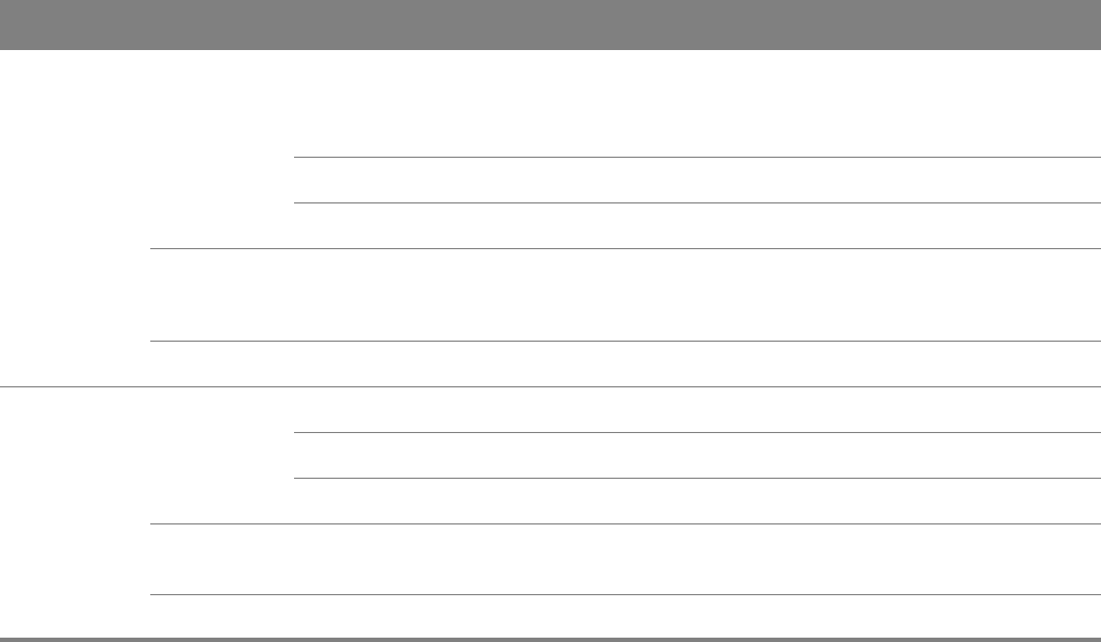
1.3 LEDs (Lights)
The following graphic displays the labels of the LEDs.
Figure 3 Front Panel LEDs
Table 2 LED Descriptions
LED COLOR STATUS DESCRIPTION
POWER Green On The Router is receiving power and ready for use.
Red On The Router has hardware failure.
Blinking The Router detected an error while self-testing.
Off The Router is not receiving power.
LAN1-4 Green On The Router has a successful Ethernet connection with a device on
the LAN.
Blinking The Router is sending or receiving data to/from the LAN.
Off The Router does not have an Ethernet connection with the LAN.
WPS/WLAN Green On The wireless network is activated.
Blinking The Router is communicating with other wireless clients.
Off The wireless network is not activated.
Yellow Blinking The Router is setting up a WPS connection.
DSL Green On The Router is connected and synchronized with the central system.
Slow Blinking The Router is detecting a VDSL line.
Fast Blinking The Router is negotiating VDSL line parameters.
Off The Router is off line or not connected to the central system.
Chapter 1 Introduction 10
Internet Green On The Router has an IP connection but no traffic.
It has a WAN IP address (either static or assigned by a DHCP server),
PPP negotiation was successfully completed (if used).
Blinking The Router is negotiating the connection.
Fast Blinking The Router is sending or receiving IP traffic.
Red On The Router attempted to make an IP connection but failed. Possible
causes are no response from a DHCP server, no PPPoE response,
PPPoE authentication failed.
Off There is no Internet connection.
VOIP Green On The SIP registration is successful.
Blinking The Router is negotiating the SIP registration.
Fast Blinking There is incoming or outgoing voice traffic.
Red On The Router has failed to register the VoIP service. There is problem
with the SIP account.
Off There is no VoIP service.
Table 2 LED Descriptions (continued)
LED COLOR STATUS DESCRIPTION
2
Chapter
Chapter 2 Introducing the Web Configurator 11
CHAPTER 2
Chapter 2 Introducing the Web Configurator
2.1 Overview
The web configurator is an HTML-based management interface that allows easy device setup and
management via Internet browser. Use Internet Explorer 6.0 and later versions, Mozilla Firefox 3
and later versions, or Safari 2.0 and later versions. The recommended screen resolution is 1024 by
768 pixels.
In order to use the web configurator you need to allow:
• Web browser pop-up windows from your device. Web pop-up blocking is enabled by default in
Windows XP SP (Service Pack) 2.
•JavaScript (enabled by default).
•Java permissions (enabled by default).
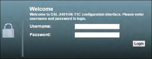
2.1.1 Accessing the Web Configurator
1Make sure your Router hardware is properly connected.
2Launch your web browser.
3T
ype "https://192.168.1.1:8000" as the URL.
4A password screen displays. Type “admin” as the default Username and the first 6 digits of the
Router’s MAC address as the default password to access the device’s Web Configurator. Click Login.
If you have changed the password, enter your password and click Login.
Figure 4 P
assword Screen
For security reasons, the Router automatically logs you out if you do not use the web
configurator for five minutes (default). If this happens, log in again.
Chapter 2 Introducing the Web Configurator 12
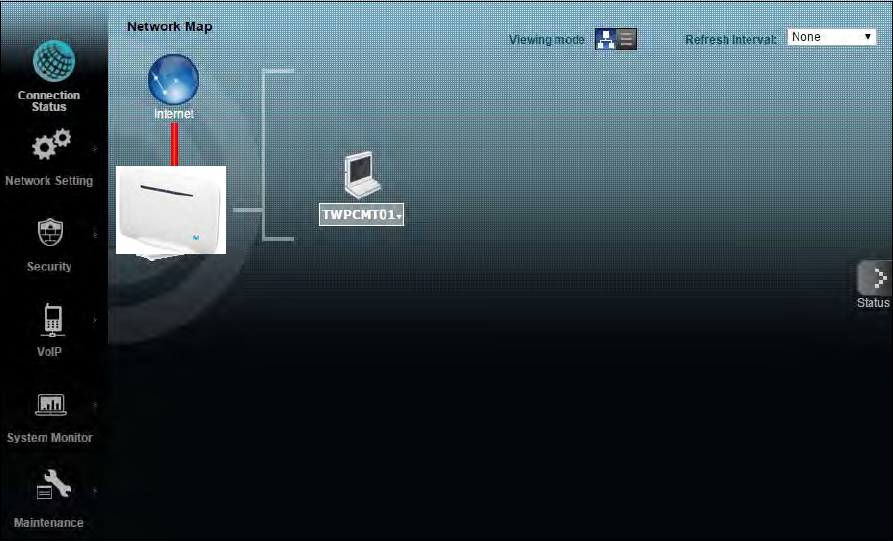
2.2 The Network Map Screen
After you log into the Web Configurator, the Network Map screen appears. This shows the network
connection status of the Router and clients connected to it.
Use this screen to view the network connection status of the device and its clients. A warning
message appears if there is a connection problem.
You can configure how often you want the Router to update this screen in Refresh Interval.
Figure 5 Network Map: Icon Mode
By clicking a client’s name in the Icon Mode, you can do the following:
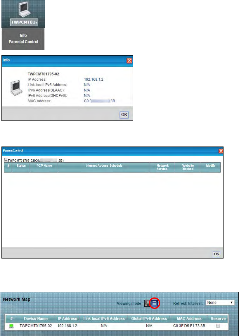
Chapter 2 Introducing the Web Configurator 13
• if you want to view information about a client, click the client’s name and Info.
• Click Parental Control to open the following screen where you can block web sites with the
specific URLs. See Chapter 12 on page 86 for more information on this feature.
If you prefer to view the status in a list, click List View in the Viewing mode selection box.
Figure 6 Network Map: List Mode
Chapter 2 Introducing the Web Configurator 14
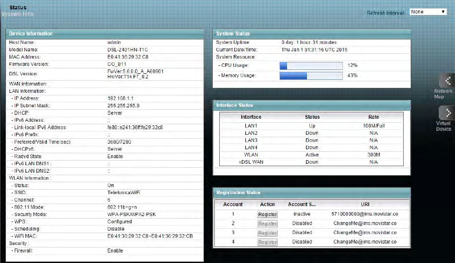
2.3 The Status Screen
Click Status to display the System Info screen, where you can view the Router’s interface and
system information. You can use the Status screen to look at the current status of the Router,
system resources, and interfaces (LAN, WAN, and WLAN).
Figure 7 System Info
Chapter 2 Introducing the Web Configurator 15
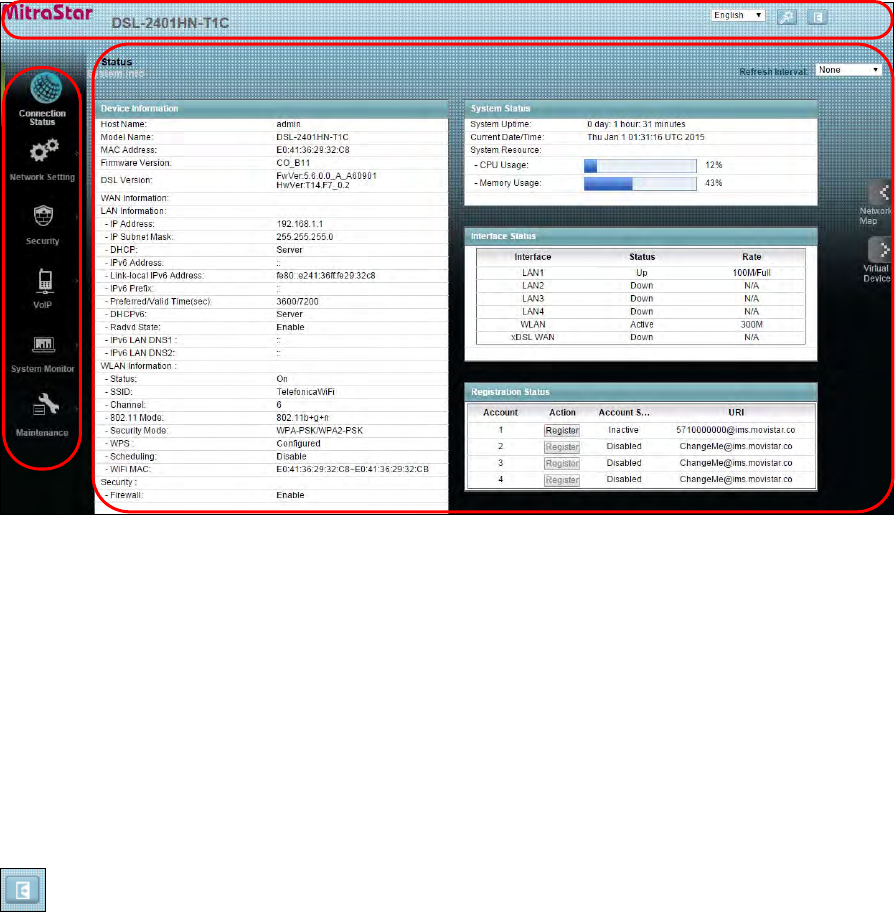
2.4 The Web Configurator Layout
Click Connection Status > System Info to show the following screen.
Figure 8 Web Configurator Layout
B
C
A
a
b
As illustrated above, the main screen is divided into these parts:
•A - title bar
•B - main window
•C - navigation panel
2.4.1 Title Bar
The title bar shows the Logout icon in the upper right corner. Click it to log out of the web
configurator.
2.4.2 Main Window
The main window displays information and configuration fields. It is discussed in the rest of this
document.
Chapter 2 Introducing the Web Configurator 16
Click Ne
twork Map on the System Info screen (a in Figure 8 on page 15) to display the Network
Map sc
reen. See Section 2.2 on page 12 for more information.
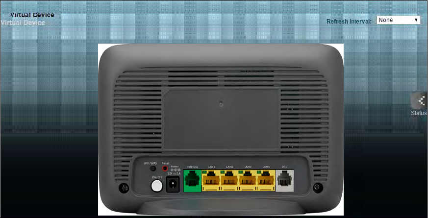
Click Virtual Device on the System Info screen (b in Figure 8 on page 15) to display a visual graphic
showing the connection status of the Router’s ports.
Figure 9 Virtual Device
3
Chapter
Chapter 3 WAN 17
CHAPTER 3
Chapter 3 WAN
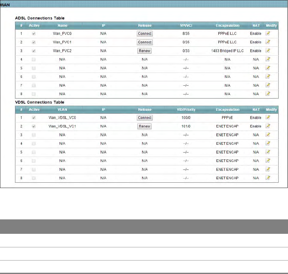
3.1 The WAN Screen
The Router must have a WAN interface to allow users to use the Ethernet connection to access the
Internet. Use the WAN screen to manage WAN interfaces. Click Network Setting > WAN.
Figure 10 Network Setting > WAN
Table 3 Network Setting > WAN
LABEL DESCRIPTION
ADSL Connections Table
Active This shows whether the ADSL connection is activated.
Name This is the service name of the ADSL connection.

Chapter 3 WAN 18
IP This shows the WAN IP address.
Release Click the Release button to release this Ethernet connection. Click the Renew
button to renew it.
VID/VCI This displays the Virtual Path Identifier (VPI) and Virtual Channel Identifier (VCI)
numbers the connection uses.
Encapsulation This shows the method of encapsulation used by this connection.
NAT This shows whether NAT is activated or not for this connection. NAT is not available
when the connection uses the bridging service.
Modify Click the Edit icon to configure the connection.
VDSL Connections Table
Active This shows whether the VDSL connection is activated.
VLAN This is the service name of the connection.
IP This shows the WAN IP address.
Release Click the Release button to release this Ethernet connection. Click the Renew
button to renew it.
VID/Priority This is the VLAN ID and IEEE 802.1p priority.
Encapsulation This shows the method of encapsulation used by this connection.
NAT This shows whether NAT is activated or not for this connection. NAT is not available
when the connection uses the bridging service.
Modify Click the Edit icon to configure the connection.
Table 3 Network Setting > WAN (continued)
LABEL DESCRIPTION
Chapter 3 WAN 19
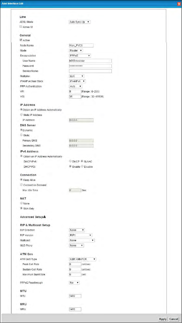
3.1.1 Edit ADSL Ethernet Connection
In Network Setting > WAN, click the Edit icon next to an ADSL Ethernet connection to display the
following screen. Use this screen to configure an ADSL connection.
Figure 11 Network Setting > WAN: ADSL: Edit

Chapter 3 WAN 20
Table 4 Network Setting > WAN: ADSL: Edit
LABEL DESCRIPTION
Line
ADSL Mode Select the kind of connection your Router uses to connect to the ISP.
Use Auto Sync-Up if you are not sure which mode to choose from. The Router dynamically
diagnoses the mode supported by the ISP and selects the best compatible one for your
connection.
Use ADSL2+ or T1.413 if you know the specific type of DSL the Router uses to connect to the
ISP.
Other options are VDSL2, ADSL2, G.DMT, T1.413 and G.lite.
Annex M Select this if your ISP supports it.
General
Active Select this to have the Router use the Ethernet connection.
Node Name Specify the name for this WAN interface.
Mode Select Router (default) if your ISP gives you one IP address only and you want multiple
computers to share an Internet account. Select Bridge when your ISP provides you more than
one IP address and you want the connected computers to get individual IP address from the
ISP’s DHCP server directly. If you select Bridge, you cannot use Firewall, DHCP server and NAT
on the Router.
Encapsulation Select the method of encapsulation used by your ISP. Choices vary depending on the mode
you select in the Mode field.
If you select Router in the Mode field, select ENET ENCAP, IPoA, PPPoE, or PPPoA.
If you select Bridge in the Mode field, method of encapsulation is not available.
User Name (PPPoE encapsulation only) Enter the user name exactly as your ISP assigned. If assigned a
name in the form user@domain where domain identifies a service name, then enter both
components exactly as given.
Password (PPPoE or PPPoA encapsulation) Enter the password associated with the user name above.
Service Name (PPPoE or PPPoA encapsulation) Type the name of your PPPoE or PPPoA service here.
Multiplex Select the method of multiplexing your ISP uses. Choices are VC-Mux or LLC.
By prior agreement, a protocol is assigned a specific virtual circuit, for example, VC1 will carry
IP. If you select VC-Mux, specify separate VPI and VCI numbers for each protocol.
For LLC-based multiplexing or PPP encapsulation, one VC carries multiple protocols with
protocol identifying information being contained in each packet header. In this case, only one
set of VPI and VCI numbers need be specified for all protocols.
IPv6/IPv4 Dual
Stack Select IPv4 if you want the Router to run IPv4 only.
Select IPv4/IPv6 to allow the Router to run IPv4 and IPv6 at the same time.
Select IPv6 if you want the Router to run IPv6 only.

Chapter 3 WAN 21
PPP
Authentication Select an authentication protocol for outgoing calls:
AUTO - Your Router accepts either CHAP or PAP when requested by this remote node.
CHAP - Your Router accepts CHAP only.
PAP - Your Router accepts PAP only.
VPI The valid range for the VPI is 0 to 255. Enter the VPI assigned to you.
VCI The valid range for the VCI is 32 to 65535 (0 to 31 is reserved for local management of ATM
traffic). Enter the VCI assigned to you.
IP Address
Obtain an IP
Address
Automatically
Select this option to use a dynamic IP address.
Static IP Address Select this option if the ISP gave them a specific IP address to use.
IP Address This option is available if you select Router in the Mode field and IPv4 or IPv4/IPv6 in the
IPv6/IPv4 Dual Stack field.
Enter the IP address your ISP has assigned.
DNS Server
Dynamic Select this option to use a dynamic DNS server.
Static Select this option if the ISP gave them a specific DNS server to use.
Primary DNS Enter the primary DNS server’s address for the Router.
Secondary DNS Enter the secondary DNS server’s address for the Router.
IPv6 Address
Obtain an IP
Address
Automatically
Select this option to obtain an IPv6 address automatically.
DHCP IPv6 Select DHCP to obtain an IPv6 address from a DHCPv6 server. Select SLAAC to have the
Router use the prefix to automatically generate a unique IP address that does not need to be
maintained by a DHCP server.
DHCP PD Select Enable to use DHCP PD (Prefix Delegation) to allow the Router to pass the IPv6 prefix
information to its LAN hosts. The hosts can then use the prefix to generate their IPv6
addresses.
Static IPv6
Address If you select Static IPv6 Address, enter the IPv6 address and the address prefix length that
the Router uses.
IPv6 Address Enter the IPv6 address assigned by your ISP.
Prefix length Enter the address prefix length to specify how many most significant bits in an IPv6 address
compose the network address.
Table 4 Network Setting > WAN: ADSL: Edit (continued)
LABEL DESCRIPTION

Chapter 3 WAN 22
IPv6 DNS
Server1/2 Enter the first and second IPv6 DNS server address assigned by the ISP.
Connection (PPPoA and PPPoE encapsulation only)
Keep Alive Select Keep Alive when you want your connection up all the time. The Router will try to bring
up the connection automatically if it is disconnected.
Connect on
Demand Select Connect on Demand when you don't want the connection up all the time and specify
an idle time-out in the Max Idle Timeout field.
Max Idle Timeout Specify an idle time-out in the Max Idle Timeout field when you select Connect on Demand.
The default setting is 0, which means the Internet session will not timeout.
NAT
None Select None to disable NAT.
SUA Only Select SUA Only if you have one public IP address and want to use NAT.
Advanced Setup
RIP & Multicast Setup
RIP Direction Select the RIP Direction from None, Both, In Only and Out Only.
RIP Version This field is not configurable if you select None in the RIP Direction field.
Select the RIP version from RIP1 and RIP2-B/RIP2-M.
Multicast The Router supports IGMP v2 only and IGMP v2/IGMP v3. Select None to disable it.
ATM Qos
ATM QoS Type This section is available when the connection’s Virtual Channel field is set to an ADSL option.
Peak Cell Rate Select CBR (Continuous Bit Rate) to specify fixed (always-on) bandwidth for voice or data
traffic. Select UBR With PCR (Unspecified Bit Rate with Peak Cell Rate) for applications that
are non-time sensitive, such as e-mail. Select Non Realtime VBR (Variable Bit Rate-non Real
Time) or Realtime VBR (Variable Bit Rate-Real Time) for bursty traffic and bandwidth sharing
with other applications.
Sustain Cell Rate Divide the DSL line rate (bps) by 424 (the size of an ATM cell) to find the Peak Cell Rate (PCR).
This is the maximum rate at which the sender can send cells. Type the PCR here.
Maximum Burst
Size
The Sustain Cell Rate (SCR) sets the average cell rate (long-term) that can be transmitted. Type
the SCR, which must be less than the PCR. Note that system default is 0 cells/sec.
Table 4 Network Setting > WAN: ADSL: Edit (continued)
LABEL DESCRIPTION

Chapter 3 WAN 23
PPPoE
Passthrough
his field is available when you select PPPoE encapsulation.
In addition to the Router’s built-in PPPoE client, you can select Yes to enable PPPoE pass
through to allow up to ten hosts on the LAN to use PPPoE client software on their computers
to connect to the ISP via the Router. Each host can have a separate account and a public WAN
IP address. PPPoE pass through is an alternative to NAT for application where NAT is not
appropriate.
Select No to disable PPPoE pass through if you do not need to allow hosts on the LAN to use
PPPoE client software on their computers to connect to the ISP.
MTU
MTU Enter the MTU (Maximum Transmission Unit) for this WAN interface.
MRU
MRU Enter the MRU (Maximum Receive Unit) for this WAN interface.
Table 4 Network Setting > WAN: ADSL: Edit (continued)
LABEL DESCRIPTION
Chapter 3 WAN 24
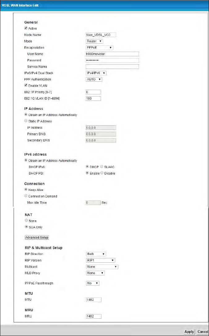
3.1.2 Edit VDSL Ethernet Connection
In Network Setting > WAN, click the Edit icon next to a VDSL Ethernet connection to display the
following screen. Use this screen to configure a VDSL connection.
Figure 12 Network Setting > WAN: VDSL: Edit

Chapter 3 WAN 25
Table 5 Network Setting > WAN: VDSL: Edit
LABEL DESCRIPTION
Active Select this to have the Router use the VDSL Ethernet connection.
Node Name Specify the name for this WAN interface.
Mode Select Router (default) if your ISP gives you one IP address only and you want multiple
computers to share an Internet account. Select Bridge when your ISP provides you more than
one IP address and you want the connected computers to get individual IP address from the
ISP’s DHCP server directly. If you select Bridge, you cannot use Firewall, DHCP server and NAT
on the Router.
Encapsulation Select the method of encapsulation used by your ISP. Choices vary depending on the mode
you select in the Mode field.
If you select Router in the Mode field, select ENET ENCAP or PPPoE.
If you select Bridge in the Mode field, method of encapsulation is not available.
User Name (PPPoE encapsulation only) Enter the user name exactly as your ISP assigned. If assigned a
name in the form user@domain where domain identifies a service name, then enter both
components exactly as given.
Password (PPPoE encapsulation only) Enter the password associated with the user name above.
Service Name (PPPoE only) Type the name of your PPPoE service here.
IPv6/IPv4 Dual Stack Select IPv4 if you want the Router to run IPv4 only.
Select IPv4/IPv6 to allow the Router to run IPv4 and IPv6 at the same time.
Select IPv6 if you want the Router to run IPv6 only.
PPP
Authentication Select an authentication protocol for outgoing calls:
AUTO - Your Router accepts either CHAP or PAP when requested by this remote node.
CHAP - Your Router accepts CHAP only.
PAP - Your Router accepts PAP only.
Enable VLAN Select this to enable VLAN on the WAN connection. You can configure the IEEE 802.1p priority
level and VLAN ID number for this connection.
802.1P Priority IEEE 802.1p defines up to 8 separate traffic types by inserting a tag into a MAC-layer frame
that contains bits to define class of service.
Select the IEEE 802.1p priority level (from 0 to 7) to add to traffic through this connection. The
greater the number, the higher the priority level.
802.1Q VLAN ID Enter the VLAN ID number (from 1 to 4094) for traffic through this connection.
IP Address This option is available if you select Router in the Mode field and IPv4 or IPv4/IPv6 in the
IPv6/IPv4 Dual Stack field.
Select Static IP Address if the ISP gave them a specific IP address to use, otherwise select
Obtain an IP Address Automatically to use a dynamic IP address.
IP Address Enter the IP address your ISP has assigned.

Chapter 3 WAN 26
Primary DNS Enter the primary DNS server’s address for the Router.
Secondary DNS Enter the secondary DNS server’s address for the Router.
IPv6 address This option is available if you select Router in the Mode field and IPv6 or IPv4/IPv6 in the
IPv6/IPv4 Dual Stack field.
If you select ENET ENCAP in the Encapsulation field, select Obtain an IP Address
Automatically if you have a dynamic IPv6 address; otherwise select Static IP Address.
If your encapsulation mode is PPPoE, the Router’s IPv6 address is dynamic and you do not
need to configure the IPv6 address settings.
IPv6 Address Enter the IPv6 address assigned by your ISP.
Prefix length Enter the address prefix length.
IPv6 Default
Gateway Enter the default gateway.
IPv6 DNS Server1 Enter the first IPv6 DNS server address.
IPv6 DNS Server2 Enter the second IPv6 DNS server address.
DHCP IPv6 This is available only when you select Obtain an IP Address Automatically.
Select DHCP to obtain an IPv6 address from a DHCPv6 server. Select SLAAC to have the
Router use the prefix to automatically generate a unique IP address that does not need to be
maintained by a DHCP server.
DHCP PD This is available only when you select Obtain an IP Address Automatically.
Select Enable to use DHCP PD (Prefix Delegation) to allow the Router to pass the IPv6 prefix
information to its LAN hosts. The hosts can then use the prefix to generate their IPv6
addresses.
Connection (PPPoE encapsulation only)
Keep Alive Select Keep Alive when you want your connection up all the time. The Router will try to bring
up the connection automatically if it is disconnected.
Connect on
Demand Select Connect on Demand when you don't want the connection up all the time and specify
an idle time-out in the Max Idle Timeout field.
Max Idle Timeout Specify an idle time-out in the Max Idle Timeout field when you select Connect on Demand.
The default setting is 0, which means the Internet session will not timeout.
NAT SUA Only is available only when you select Router in the Mode field.
Select SUA Only if you have one public IP address and want to use NAT.
Select None to disable NAT.
Advanced Setup Click this to display or hide RIP and multicast and MTU fields.
RIP & Multicast Setup
RIP Direction Select the RIP Direction from None, Both, In Only and Out Only.
Table 5 Network Setting > WAN: VDSL: Edit (continued)
LABEL DESCRIPTION

Chapter 3 WAN 27
RIP Version This field is not configurable if you select None in the RIP Direction field.
Select the RIP version from RIP-1 and RIP2-B/RIP2-M.
Multicast The Router supports IGMP-v1, IGMP-v2 and IGMP-v3. Select None to disable it.
MLD Proxy Select MLD v1 or MLD v2 to have the Router act as an MLD proxy on this connection. This
allows the Router to get subscription information and maintain a joined member list for each
multicast group. It can reduce multicast traffic significantly.
Select None to disable this feature.
PPPoE
Passthrough
his field is available when you select PPPoE encapsulation.
In addition to the Router’s built-in PPPoE client, you can select Yes to enable PPPoE pass
through to allow up to ten hosts on the LAN to use PPPoE client software on their computers
to connect to the ISP via the Router. Each host can have a separate account and a public WAN
IP address. PPPoE pass through is an alternative to NAT for application where NAT is not
appropriate.
Select No to disable PPPoE pass through if you do not need to allow hosts on the LAN to use
PPPoE client software on their computers to connect to the ISP.
MTU
MTU Enter the MTU for this WAN interface in this field.
MRU
MRU Enter the MRU (Maximum Receive Unit) for this WAN interface.
Table 5 Network Setting > WAN: VDSL: Edit (continued)
LABEL DESCRIPTION
4
Chapter
Chapter 4 Wireless 2.4GHz 28
CHAPTER 4
Chapter 4 Wireless 2.4GHz
4.1 Wireless General Screen
Use this screen to enable the Wireless LAN, enter the SSID and select the wireless security mode.
If you are configuring the Router from a computer connected to the wireless LAN and you
change the Router’s SSID or security settings, you will lose your wireless connection when
you press Apply to confirm. You must then change the wireless settings of your computer
to match the Router’s new settings.
Click Network Setting > Wireless 2.4GHz to open the General screen. Select the Enable Wireless
LAN check box to show the Wireless configurations.
Figure 13 Network Setting > Wireless 2.4GHz > General
Chapter 4 Wireless 2.4GHz 29
Table 6 Network Setting > Wireless 2.4GHz > General
LABEL DESCRIPTION
Wireless Select the Enable Wireless LAN check box to activate the wireless LAN.
Wireless
Network Name
(SSID)
Enter a descriptive name for the wireless LAN.
Hide SSID Select this check box to hide the SSID in the outgoing beacon frame so a station cannot
obtain the SSID through scanning using a site survey tool.
Client
Isolation Select this to keep the wireless clients in this SSID from communicating with each other
directly through the Router.
MBSSID/
LAN
Isolation
Select this to keep the wireless clients in this SSID from communicating with clients in
other SSIDs or wired LAN devices through the Router.
Select both Client Isolation and MBSSID/LAN Isolation to allow this SSID’s wireless
clients to only connect to the Internet through the Router.
Channel
Selection
Set the channel depending on your particular region.
Select a channel or use Auto to have the Router automatically determine a channel to
use. If you are having problems with wireless interference, changing the channel may
help. Try to use a channel that is as many channels away from any channels used by
neighboring APs as possible. The channel number which the Router is currently using
then displays in the Operating Channel field.
Scan Click this button to have the Router immediately scan for and select a channel (which is
not used by another device) whenever the device reboots or the wireless setting is
changed.
Result Click this to show the scan result of channels and their noise such as the following
screen.
Note: The country code selection is for non-US model only and is not available to all US model. Per
FCC regulation, all WiFi product marketed in US must fixed to US operation channels only.
Chapter 4 Wireless 2.4GHz 30
4.1.1 No Security
Set the Security Mode to OPEN to allow wireless stations to communicate with the Router without
any data encryption or authentication.
If you do not enable any wireless security on your Router, your network is accessible to any
wireless networking device that is within range.
Figure 14 Wireless 2.4GHz > General: OPEN
Operating
Channel
This is the channel currently being used by your AP.
Security Mode Select WEP or WPA2-PSK or WPA/WPA2 PSK mixed to add security on this wireless
network. The wireless clients which want to associate to this network must have the
same wireless security settings as the Router. When you select to use a type of wireless
security, additional options appears in this screen.
If you select OPEN, the Router allows any client to associate with this network without
any data encryption or authentication.
Table 6 Network Setting > Wireless 2.4GHz > General (continued)
LABEL DESCRIPTION
Chapter 4 Wireless 2.4GHz 31
4.1.2 Basic (WEP Encryption)
If you want to use WEP encryption for the wireless LAN, select WEP in the Security Mode field.
Figure 15 Wireless 2.4GHz > General: Basic (WEP)
Table 7 Wireless 2.4GHz > General: Basic (WEP)
LABEL DESCRIPTION
Security Level Select WEP to enable WEP data encryption.
Generate
password
automatically
Select this option to have the Router automatically generate a password.
Password The password (WEP key) is used to encrypt data. Both the Router and the wireless
stations must use the same password (WEP key) for data transmission.
WEP
Encryption
Select 64Bits or 128Bits.
This is the length of the security key that the network is going to use.
4.1.3 More Secure (WPA2-PSK or WPA/WPA2 PSK mixed)
The WPA2-PSK security mode is a newer, more robust version of the WPA encryption standard. It
offers better security.
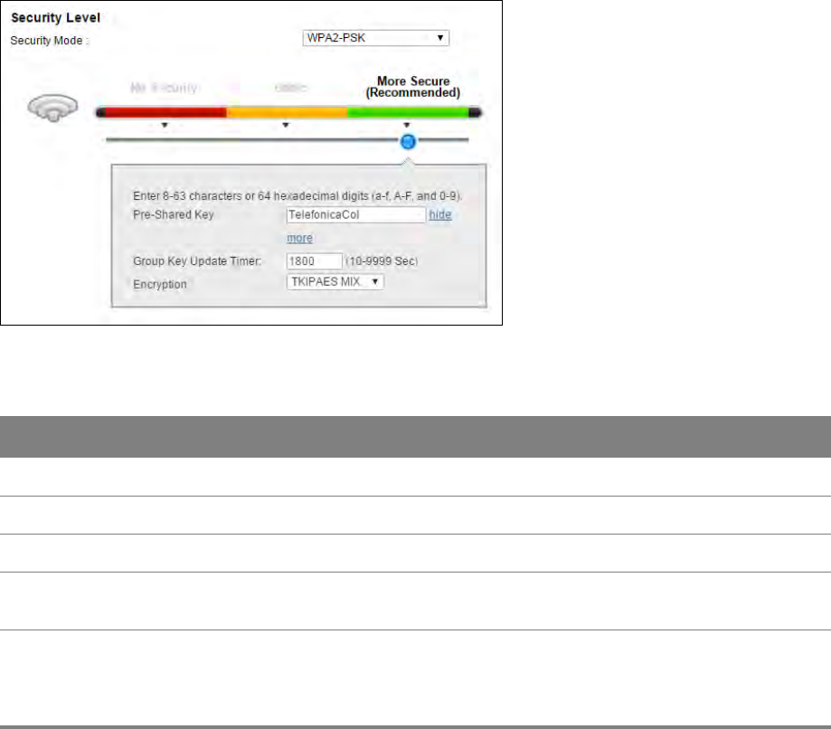
Chapter 4 Wireless 2.4GHz 32
Select WPA2-PSK or WPA/WPA2 PSK mixed from the Security Mode field.
Figure 16 Wireless 2.4GHz > General: More Secure: WPA2-PSK/WPA/WPA2 PSK mixed
Table 8 Wireless 2.4GHz > General: WPA2-PSK/WPA/WPA2 PSK mixed
LABEL DESCRIPTION
Security Mode Select WPA2-PSK or WPA/WPA2 PSK mixed as the security mode.
Pre-Shared Key Enter a pre-shared key.
more.../hide more Click more... to show more fields in this section. Click hide more to hide them.
Group Key Update
Timer
This is the rate at which the RADIUS server sends a new group key out to all clients.
Encryption Select TKIP to enable Temporal Key Integrity Protocol (TKIP) security on your wireless
network. Select AES to enable Advanced Encryption System (AES) security on your
wireless network. AES provides superior security to TKIP. Select TKIPAES MIX to have
both types of security.
Chapter 4 Wireless 2.4GHz 33
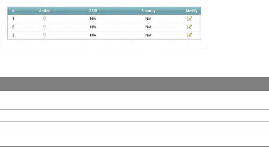
4.2 More AP Screen
This screen allows you to enable and configure multiple Basic Service Sets (BSSs) on the Router.
Click Network Setting > Wireless 2.4GHz > More AP.
Figure 17 Network Setting > Wireless 2.4GHz> More AP
Table 9 Network Setting > Wireless 2.4GHz > More AP
LABEL DESCRIPTION
Active This field indicates whether this SSID is active. A yellow bulb signifies that this SSID is
active. A gray bulb signifies that this SSID is not active.
SSID This field displays the name of the wireless profile on the network.
Security This field indicates the security mode of the SSID profile.
Modify Click the Edit icon to configure the SSID profile.
Chapter 4 Wireless 2.4GHz 34
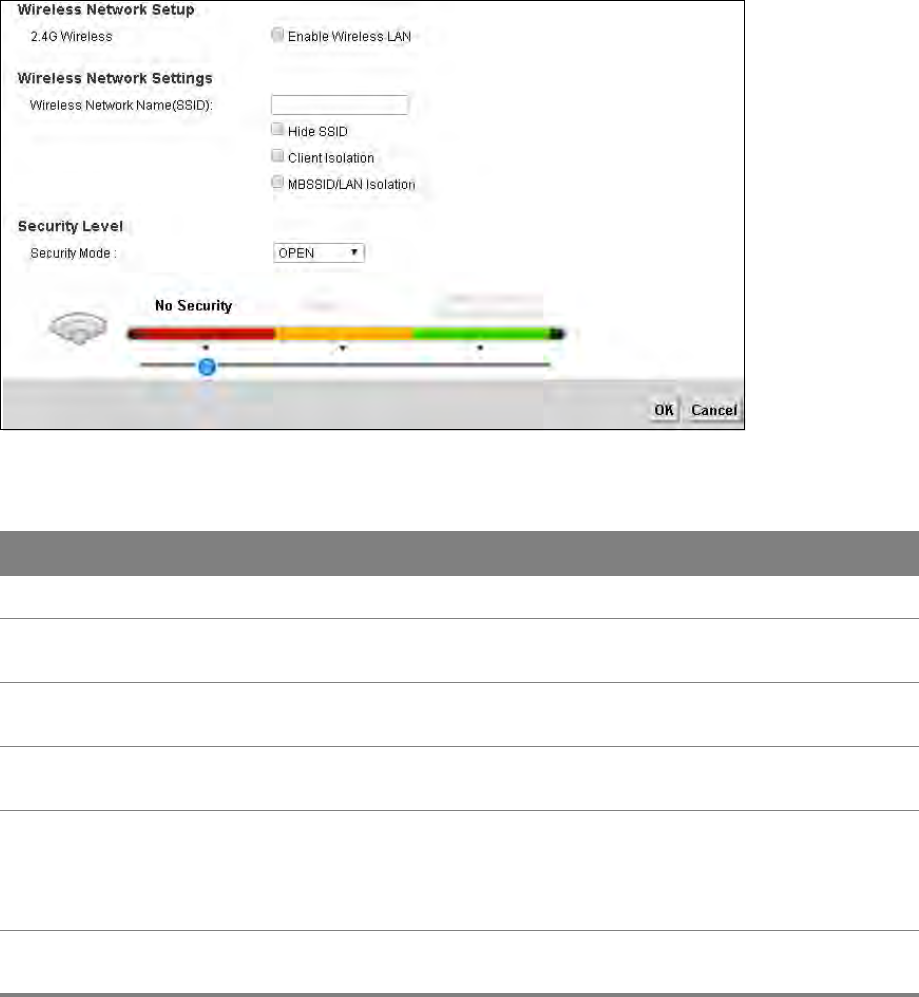
4.2.1 Edit More AP
Use this screen to edit an SSID profile. Click the Edit icon next to an SSID in the More AP screen. The
following screen displays.
Figure 18 Wireless 2.4GHz > More AP: Edit
Table 10 Wireless 2.4GHz > More AP: Edit
LABEL DESCRIPTION
2.4GHz Wireless Select Enable Wireless LAN to activate the wireless LAN.
Wireless Network
Name (SSID)
Enter a descriptive name for the wireless LAN.
Hide SSID Select this check box to hide the SSID in the outgoing beacon frame so a station
cannot obtain the SSID through scanning using a site survey tool.
Client Isolation Select this to keep the wireless clients in this SSID from communicating with each
other directly through the Router.
MBSSID/LAN Isolation Select this to keep the wireless clients in this SSID from communicating with
clients in other SSIDs or wired LAN devices through the Router.
Select both Client Isolation and MBSSID/LAN Isolation to allow this SSID’s
wireless clients to only connect to the Internet through the Router.
Security Mode Select the security mode on this wireless network. See Section 4.1.1 on page 30
through Section 4.1.3 on page 31 for more details about wireless security modes.
Chapter 4 Wireless 2.4GHz 35
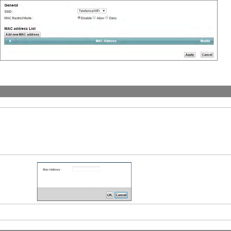
4.3 MAC Authentication Screen
Use this screen to configure the Router to give exclusive access to specific devices (Allow) or
exclude specific devices from accessing the Router (Deny).
Use this screen to view your Router’s MAC filter settings and add new MAC filter rules. Click
Network Setting > Wireless 2.4GHz > MAC Authentication.
Figure 19 Network Setting > Wireless 2.4GHz > MAC Authentication
Table 11 Network Setting > Wireless 2.4GHz > MAC Authentication
LABEL DESCRIPTION
SSID Select the SSID for which you want to configure MAC filter settings.
MAC Restrict
Mode
Define the filter action for the list of MAC addresses in the MAC Address table.
Select Disable to turn off MAC filtering.
Select Allow to permit access to the Router. MAC addresses not listed will be denied
access to the Router.
Select Deny to block access to the Router. MAC addresses not listed will be allowed to
access the Router.
Add new MAC
address
Click this and enter a new MAC address entry to add to the MAC filter list.
MAC Address This is the MAC addresses of the wireless devices that are allowed or denied access to the
Router.
Modify Click the Delete icon to delete the entry.
Chapter 4 Wireless 2.4GHz 36
4.4 The WPS Screen
Use this screen to configure WiFi Protected Setup (WPS) on your Router.
WPS allows you to quickly set up a wireless network with strong security, without having to
configure security settings manually. Set up each WPS connection between two devices. Both
devices must support WPS.
The Router applies the security settings of the SSID1 profile (see Section 4.1 on page 28). If
you want to use the WPS feature, make sure you have set the security mode of SSID1 to
WPA2-PSK or WPA-PSK/WPA2-PSK mixed or no security.
Click Network Setting > Wireless 2.4GHz > WPS. Select Enable and click Apply to activate the WPS
function. Then you can configure the WPS settings in this screen.
Figure 20 Network Setting > Wireless 2.4GHz > WPS
Table 12 Network Setting > Wireless 2.4GHz > WPS
LABEL DESCRIPTION
WPS Select Enable and click Apply to activate WPS on the Router.
Add a new device with WPS Method - These fields display after you enable WPS and click Apply.

Chapter 4 Wireless 2.4GHz 37
Method 1 PBC Use this section to set up a WPS wireless network using Push Button Configuration
(PBC).
WPS Click this button to add another WPS-enabled wireless device (within wireless range
of the Router) to your wireless network. This button may either be a physical button
on the outside of device, or a menu button similar to the WPS button on this screen.
Note: You must press the other wireless device’s WPS button within two minutes of
pressing this button.
Method 2 PIN Use this section to set up a WPS wireless network by entering the PIN (Personal
Identification Number) of the client into the Router.
Register Enter the PIN of the device that you are setting up a WPS connection with and click
Register to authenticate and add the wireless device to your wireless network.
You can find the PIN either on the outside of the device, or by checking the device’s
settings.
Note: You must also activate WPS on that device within two minutes to have it
present its PIN to the Router.
AP PIN The PIN of the Router is shown here. Enter this PIN in the configuration utility of the
device you want to connect to using WPS.
The PIN is not necessary when you use WPS push-button method.
Click the Generate New PIN button to have the Router create a new PIN.
Lock Status This displays Locked when the Router has connected to a wireless network using
WPS or WPS is enabled and wireless or wireless security settings have been changed.
The current wireless and wireless security settings also appear in the screen.
This displays Unlocked when there is no wireless or wireless security changes on the
Router or you click Release Lock to remove the configured wireless and wireless
security settings.
Release Lock This button is available when the WPS status is Locked.
Click this button to remove all configured wireless and wireless security settings for
WPS connections on the Router.
802.11 Mode This is the 802.11 mode used. Only compliant WLAN devices can associate with the
Router.
SSID This is the name of the wireless network.
Security This is the type of wireless security employed by the network.
Pre-Shared Key This is the wireless LAN password.
Table 12 Network Setting > Wireless 2.4GHz > WPS (continued)
LABEL DESCRIPTION
Chapter 4 Wireless 2.4GHz 38
4.5 The WDS Screen
The WDS screen allows you to configure the Router to connect to other APs wirelessly when WDS
(Wireless Distribution System) is enabled. Configure your WDS links between the Router and other
wireless APs. You need to know the MAC address of the peer device. Once the security settings of
peer sides match one another, the connection between devices is made. Click Network Setting >
Wireless 2.4GHz > WDS.
WDS security is independent of the security settings between the Router and any wireless
clients.
Not all APs support WDS links. Check your other AP’s documentation.
Figure 21 Network Setting > Wireless 2.4GHz > WDS
Table 13 Network Setting > Wireless 2.4GHz > WDS
LABEL DESCRIPTION
WDS Security Select the type of the key used to encrypt data between APs. All the wireless APs
(including the Router) must use the same pre-shared key for data transmission.
The option is available only when you set the security mode to WPA(2) or WPA(2)-PSK
in the Wireless > General screen.
TKIP Select this to use TKIP (Temporal Key Integrity Protocol) encryption.
AES Select this to use AES (Advanced Encryption Standard) encryption.
Active Select this to activate the link between the Router and the peer device to which this
entry refers. When you do not select the check box this link is down.
Remote Bridge
MAC Address
Type the MAC address of the peer device in a valid MAC address format (six
hexadecimal character pairs, for example 12:34:56:78:9a:bc).
PSK Enter a Pre-Shared Key (PSK).
Chapter 4 Wireless 2.4GHz 39
4.6 The WMM Screen
Use the WMM screen to enable or disable Wi-Fi MultiMedia (WMM) wireless networks for
multimedia applications. Click Network Setting > Wireless 2.4GHz > WMM.
Figure 22 Network Setting > Wireless 2.4GHz > WMM
Table 14 Network Setting > Wireless 2.4GHz > WMM
LABEL DESCRIPTION
Enable WMM of
SSID1~4
This enables the Router to automatically give a service a priority level according to the
ToS value in the IP header of packets it sends. WMM QoS gives high priority to voice
and video, which makes them run more smoothly.
Chapter 4 Wireless 2.4GHz 40
4.7 Scheduling Screen
Use the Scheduling screen to manage schedules that turn off wireless service for power saving
purposes. Click Network Setting > Wireless 2.4GHz > Scheduling.
Figure 23 Network Setting > Wireless 2.4GHz > Scheduling
Table 15 Network Setting > Wireless 2.4GHz > Scheduling
LABEL DESCRIPTION
WLAN Power Off
Scheduling
Select Enable to activate wireless LAN scheduling on your Router.
Add New Rule Click this to create a new wireless LAN scheduling rule.
Rule Name This field shows the name configured for the scheduling rule.
Days This field displays to which days of the week the schedule applies.
Start Time This field displays the time (in 24-hour time format) the rule turns off the wireless LAN.
End Time This field displays the time (in 24-hour time format) the rule turns the wireless LAN
back on.
Modify Click the Edit icon to configure the scheduling rule.
Click the Delete icon to remove the scheduling rule.
Chapter 4 Wireless 2.4GHz 41
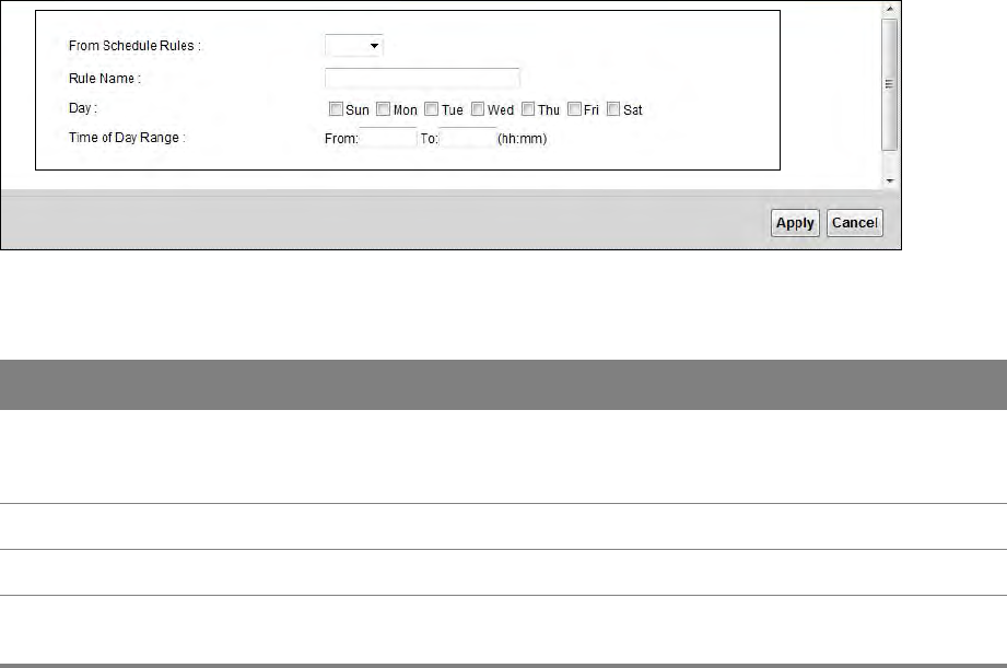
4.7.1 Add or Edit Schedule
Use this screen to add or edit a wireless LAN schedule. In the Scheduling screen, click Add New
Rule or the Edit icon next to an existing schedule.
Figure 24 Wireless 2.4GHz > Scheduling: Add New Rule
Table 16 Wireless 2.4GHz > Scheduling: Add New Rule
LABEL DESCRIPTION
From
Schedule
Rules
To create a new scheduling rule based off an existing one, select it here.
Rule Name Specify a descriptive name to identify the scheduling rule.
Day Select the days of the week to which to apply the schedule.
Time of Day
Range
Enter the time for turning the wireless LAN service off and back on in 24-hour time format.
Chapter 4 Wireless 2.4GHz 42
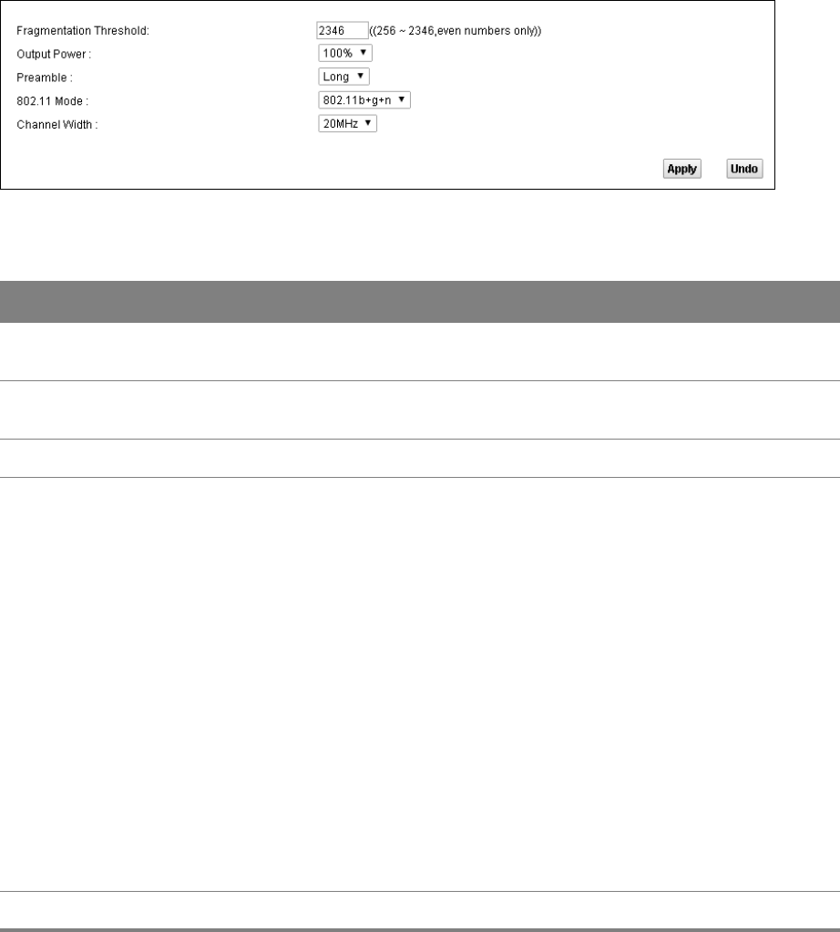
4.8 Advanced Screen
Use the Advanced screen to configure advanced wireless settings. Click Network Setting >
Wireless 2.4GHz > Advanced.
Figure 25 Network Setting > Wireless 2.4GHz > Advanced
Table 17 Network Setting > Wireless 2.4GHz > Advanced
LABEL DESCRIPTION
Fragmentation
Threshold
Enter the maximum data fragment size that can be sent.
Output Power Set the output power of the Router. If there is a high density of APs in an area, decrease
the output power to reduce interference with other APs.
Preamble Select a preamble type from the drop-down list menu.
802.11 Mode Select 802.11b to allow only IEEE 802.11b compliant WLAN devices to associate with the
Router.
Select 802.11g to allow only IEEE 802.11g compliant WLAN devices to associate with the
Router.
Select 802.11b+g to allow either IEEE 802.11b or IEEE 802.11g compliant WLAN devices
to associate with the Router. The transmission rate of your Router might be reduced.
Select 802.11n to allow only IEEE 802.11n compliant WLAN devices to associate with the
Router.
Select 802.11g+n to allow either IEEE 802.11g or IEEE 802.11n compliant WLAN devices
to associate with the Router. The transmission rate of the Router might be reduced
when an 802.11g wireless client is associated with it.
Select 802.11b+g+n to allow IEEE 802.11b, IEEE 802.11g or IEEE 802.11n compliant
WLAN devices to associate with the Router. The transmission rate of the Router might
be reduced when an 802.11b or 802.11g wireless client is associated with it.
Note: The transmission rate varies depending on the mode the wireless client uses to
associate with the Router.
Channel Width Select the wireless channel width that the Router uses.
5
Chapter
Chapter 5 LAN 43
CHAPTER 5
Chapter 5 LAN
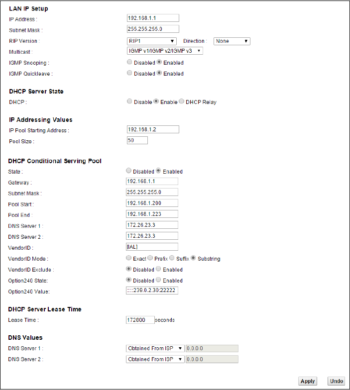
5.1 The LAN Setup Screen
Click Network Setting > LAN to open the LAN Setup screen. Use this screen to set the Local Area
Network IP address and subnet mask of your Router and configure the DNS server information that
the Router sends to the DHCP client devices on the LAN.
Figure 26 Network Setting > LAN > LAN Setup

Chapter 5 LAN 44
Table 18 Network Setting > LAN > LAN Setup
LABEL DESCRIPTION
IP Address Enter the LAN IP address you want to assign to your Router. The factory default is
192.168.1.1.
IP Subnet Mask Type the subnet mask of your network. The factory default is 255.255.255.0. Your
Router automatically computes the subnet mask based on the IP address you enter,
so do not change this field unless you are instructed to do so.
RIP Version Specify the RIP (Routing Information Protocol) version, which allows a router to
exchange routing information with other routers.
Direction Specify how much routing information the Router sends and receives on the subnet.
Multicast IGMP (Internet Group Multicast Protocol) is a network-layer protocol used to
establish membership in a multicast group.
IGMP Snooping Select Enabled to activate IGMP Snooping. This allows the Router to passively learn
memberships in multicast groups. Otherwise, select Disabled to deactivate it.
IGMP Quickleave Select Enabled to immediately removes a port when the Router detects an IGMP
version 2 leave message on that port.
DHCP Select Enable to have the Router assign IP addresses, an IP default gateway and DNS
servers to LAN computers and other devices that are DHCP clients.
Select DHCP Relay to have the Router forward DHCP requests to the DHCP server.
If you select Disable, you need to manually configure the IP addresses of the
computers and other devices on your LAN.
You need to configure the following fields if you select Enable or DHCP Relay.
DHCP Relay Server
Address
If you set DHCP to DHCP Relay, enter the IP address of the DHCP relay server.
IP Pool Starting
Address
Specify the first of the contiguous addresses in the IP address pool.
Pool Size Specify the size, or count of the IP address pool.
State Select Enable to enable the DHCP conditional serving pool for the IPTV. DHCP server
will offer IP address from the conditional pool if the DHCP request sent from a set-
top box contains the specific Vendor ID.
Gateway Enter the IPTV server’s IP address.
Subnet Mask Enter the IPTV server’s subnet mask.
Pool Start/End Specify the first and last of the contiguous addresses in the IPTV server’s IP address
pool.
DNS Server 1/2 Enter the IPTV server’s first/second DNS server IP address.
VendorID Specify the IPTV’s vendor ID.
Chapter 5 LAN 45
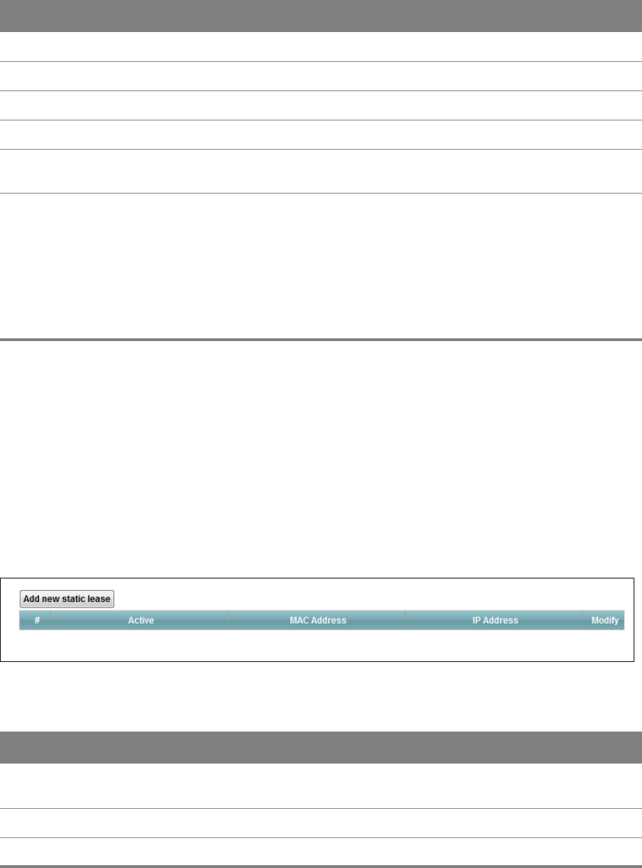
5.2 The Static DHCP Screen
Use the Static DHCP screen to change your Router’s static DHCP settings. This table allows you to
assign IP addresses on the LAN to specific individual computers based on their MAC Addresses. Find
out the MAC addresses of your network devices if you intend to add them to the Static DHCP
screen.
Click Network Setting > LAN > Static DHCP.
Figure 27 Network Setting > LAN > Static DHCP
VendorID Mode Specify the IPTV’s vendor ID mode type.
VendorID Exclude Specify if you want to enable vendor ID exclude.
Option240 State Select Enabled to have the Router assign DHCP option 240 to the LAN set top box.
Option240 Value Enter the option 240 value.
Lease Time Specify for how long it takes to assign an IP address to a LAN device before making it
available for reassignment to other systems.
DNS Server 1/2 Select Obtained From ISP if your ISP dynamically assigns DNS server information
(and the Router's WAN IP address).
Select User-Defined if you have the IP address of a DNS server. Enter the DNS
server's IP address in the field to the right.
Select DNS Proxy to have the DHCP clients use the Router’s own LAN IP address.
The Router works as a DNS relay.
Select None to not configure extra DNS servers.
Table 18 Network Setting > LAN > LAN Setup (continued)
LABEL DESCRIPTION
Table 19 Network Setting > LAN > Static DHCP
LABEL DESCRIPTION
Add new static
lease
Click this to add a new static DHCP entry.
Active This field displays whether the client is connected to the Router.
MAC Address This field displays the MAC address of the client on the LAN.
Chapter 5 LAN 46
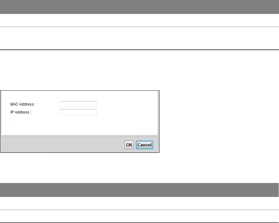
If you click Add new static lease in the Static DHCP screen, the following screen displays.
Figure 28 LAN > Static DHCP: Add
Table 20 LAN > Static DHCP: Add
LABEL DESCRIPTION
MAC Address Enter the MAC address of a computer on your LAN.
IP Address Enter the IP address that you want to assign to the computer on your LAN.
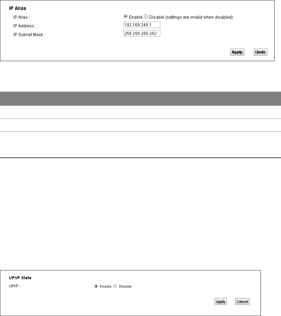
5.3 The IP Alias Screen
IP alias allows you to partition a physical network into different logical networks over the same
Ethernet interface. The Router supports multiple logical LAN interfaces via its physical Ethernet
interface with the Router itself as the gateway for the LAN network.
When you use IP alias, you can also configure firewall rules to control access to the LAN's logical
network (subnet).
IP Address This field displays the IP address of the client on the LAN.
Modify Click the Edit icon to edit the static DHCP settings.
Click the Delete icon to remove it.
Table 19 Network Setting > LAN > Static DHCP (continued)
LABEL DESCRIPTION
Chapter 5 LAN 47
Use the IP Alias screen to change your Router’s IP alias settings. Click Network Setting > LAN > IP
Alias.
Figure 29 Network Setting > LAN > IP Alias
Table 21 Network Setting > LAN > IP Alias
LABEL DESCRIPTION
IP Alias Select Enable to configure another LAN network for the Router.
IP Address Enter the second LAN IP address of your Router.
Subnet Mask Your Router will automatically calculate the subnet mask based on the IP address
that you assign. Unless you are implementing subnetting, use the subnet mask
computed by the Router.
5.4 The UPnP Screen
Universal Plug and Play (UPnP) is a distributed, open networking standard that uses TCP/IP for
simple peer-to-peer network connectivity between devices. A UPnP device can dynamically join a
network, obtain an IP address, convey its capabilities and learn about other devices on the network.
In turn, a device can leave a network smoothly and automatically when it is no longer in use.
Use the UPnP screen to enable the UPnP feature on your Router. Click Network Setting > Home
Networking > LAN > UPnP.
Figure 30 Network Setting > LAN > UPnP
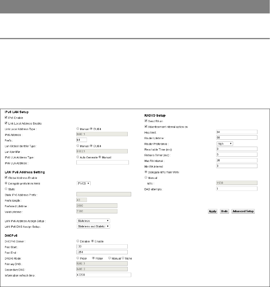
Table 22 Network Settings > LAN > UPnP
LABEL DESCRIPTION
UPnP Select Enable to activate UPnP. Be aware that anyone could use a UPnP application to
open the web configurator's login screen without entering the Router's IP address
(although you must still enter the password to access the web configurator).
Chapter 5 LAN 48
5.5 The IPv6 LAN Setup Screen
Use the IPv6 LAN Setup screen to set the Local Area Network interface IPv6 settings. Click
Network Setting > LAN > IPv6 LAN Setup.
Figure 31 Network Setting > LAN > IPv6 LAN Setup

Chapter 5 LAN 49
Table 23 Network Setting > LAN > IPv6 LAN Setup
LABEL DESCRIPTION
IPv6 Enable Select this to enable the IPv6 feature on the Router.
Link Local Address
Enable
Select this to enable the Link Local Address feature on the Router.
Link Local Address
Type
Select Manual to manually enter a link local address. Select EUI64 to use the EUI-64
format to generate a link local address from the Ethernet MAC address.
IPv6 Address If you selected Manual in the Link Local Address Type field, enter the LAN IPv6
address you want to assign to your Router.
Prefix Enter the address prefix to specify how many most significant bits in an IPv6 address
compose the network address.
Lan Global
Identifier Type
Select Manual to manually enter a LAN identifier as the interface ID to identify the
LAN interface. The LAN identifier is appended to the IPv6 address prefix to create the
routable global IPv6 address.
Select EUI64 to use the EUI-64 format to generate an interface ID from the Ethernet
MAC address.
Lan Identifier If you selected Manual, enter the LAN identifier. The LAN identifier should be unique
and 64 bits in hexadecimal form.
IPv6 ULA Address
Type
A unique local address (ULA) is a unique IPv6 address for use in private networks but
not routable in the global IPv6 Internet.
Select Auto Generate to have the Router automatically generate a globally unique
address for the LAN IPv6 address. Select Manual to enter a static IPv6 ULA address.
IPv6 ULA Address If you select Manual in the IPv6 ULA Address Type field, enter a static IPv6 ULA
address.
Global Address
Enable
Select this to enable IPv6 global address.
Delegate prefix
from WAN
Select this option to automatically obtain an IPv6 network prefix from the service
provider or an uplink router.
Static Select this option to configure a fixed IPv6 address for the Router’s LAN IPv6 address.
Static IPv6
Address Prefix
If you select static IPv6 address, enter the IPv6 address prefix that the Device uses for
the LAN IPv6 address.
Prefix length If you select static IPv6 address, enter the IPv6 prefix length that the Device uses to
generate the LAN IPv6 address.
Preferred
Lifetime
Enter the preferred lifetime for the prefix.
Valid Lifetime Enter the valid lifetime for the prefix.

Chapter 5 LAN 50
LAN IPv6
Address Assign
Setup
Select how you want to obtain an IPv6 address:
•Stateless: The Router uses IPv6 stateless autoconfiguration. RADVD (Router
Advertisement Daemon) is enabled to have the Router send IPv6 prefix
information in router advertisements periodically and in response to router
solicitations. DHCPv6 server is disabled.
•Stateful: The Router uses IPv6 stateful autoconfiguration. The DHCPv6 server is
enabled to have the Router act as a DHCPv6 server and pass IPv6 addresses to
DHCPv6 clients.
•Stateless and Stateful: The Router uses both IPv6 stateless and stateful
autoconfiguration. The LAN IPv6 clients can obtain IPv6 addresses either through
router advertisements or through DHCPv6.
LAN IPv6 DNS
Assign Setup
Select how the Router provides DNS server and domain name information to the
clients:
•Stateless: The Router uses IPv6 stateless autoconfiguration. RADVD (Router
Advertisement Daemon) is enabled to have the Router send IPv6 prefix
information in router advertisements periodically and in response to router
solicitations. DHCPv6 server is disabled.
•Stateful: The Router uses IPv6 stateful autoconfiguration. The DHCPv6 server is
enabled to have the Router act as a DHCPv6 server and pass IPv6 addresses to
DHCPv6 clients.
•Stateless and Stateful: The Router uses both IPv6 stateless and stateful
autoconfiguration. The LAN IPv6 clients can obtain IPv6 addresses either through
router advertisements or through DHCPv6.
DHCPv6 Server Select Enable to have the Router act as a DHCPv6 server and pass IPv6 addresses,
DNS server and domain name information to DHCPv6 clients.
Pool Start/End Specify the first/last IPv6 address in the pool of addresses that can be assigned to
DHCPv6 clients.
DNSv6 Mode Select the DNS role (Proxy or Relay) that you want the Router to act in the IPv6 LAN
network. Alternatively, select Manual and specify the DNS servers’ IPv6 address in the
fields below. Select None to disable this feature.
Primary/
Secondary DNS
This field is available if you select Manual as the DNSv6 mode. Enter the first/second
DNS server IPv6 address the Router passes to the DHCP clients.
DNS Query Mode Select how the Router handles clients’ DNS information requests.
•IPv4 DNS Server First: The Router forwards the requests to the IPv4 DNS server
first and then the IPv6 DNS server. Then it sends clients the first DNS information it
receives.
•IPv6 DNS Server First: The Router forwards the requests to the IPv6 DNS server
first and then the IPv4 DNS server. Then it sends clients the first DNS information it
receives.
•IPv4 DNS Server Only: The Router forwards the requests to the IPv4 DNS server
and sends clients the DNS information it receives.
•IPv6 DNS Server Only: The Router forwards the requests to the IPv6 DNS server
and sends clients the DNS information it receives.
Information
Refresh Time
Enter the number of seconds a DHCPv6 client should wait before refreshing
information retrieved from DHCPv6.
Advanced Setup Click this to show the RADVD Setup section. Click the button again to close it.
Table 23 Network Setting > LAN > IPv6 LAN Setup (continued)
LABEL DESCRIPTION

Chapter 5 LAN 51
Network Connections: My Network Places: Properties: Example
Send RA on Select this to have the Router send RA (Router Advertisement) messages to the LAN
hosts.
Note: The LAN hosts neither generate global IPv6 addresses nor communicate with
other networks if you disable this feature.
Advertisement
interval option on
Select this to have the RA messages the Router sends specify the allowed interval
between RA messages.
Hop Limit Enter the maximum number of network segments that a packet can cross before
reaching the destination. When forwarding an IPv6 packet, IPv6 routers are required to
decrease the Hop Limit by 1 and to discard the IPv6 packet when the Hop Limit is 0.
Router Lifetime Enter the time in seconds that hosts should consider the Router to be the default
router.
Router Preference Select the router preference for the Router. The Router sends this preference in the
router advertisements to tell hosts what preference they should use for the Router.
This helps hosts to choose their default router especially when there are multiple IPv6
routers in the network.
Note: Make sure the hosts also support router preference to make this function work.
Reachable Time
(ms)
Enter the time in milliseconds that can elapse before a neighbor is detected.
Retrans Time (ms) Enter the time in milliseconds between neighbor solicitation packet retransmissions.
Max RA Interval Enter the maximum time between RA messages.
Min RA Interval Enter the minimum time between RA messages.
Delegate MTU
from WAN
Select this to have the Router obtain the MTU setting from the service provider or
uplink router.
Manual Select this to specify the MTU manually.
MTU Enter the MTU value.
DAD Attempts Specify the number of DAD (Duplicate Address Detection) attempts before an IPv6
address is assigned to the Router LAN interface.
Table 23 Network Setting > LAN > IPv6 LAN Setup (continued)
LABEL DESCRIPTION
6
Chapter
Chapter 6 Static Route 52
CHAPTER 6
Chapter 6 Static Route
6.1 Configuring Static Route
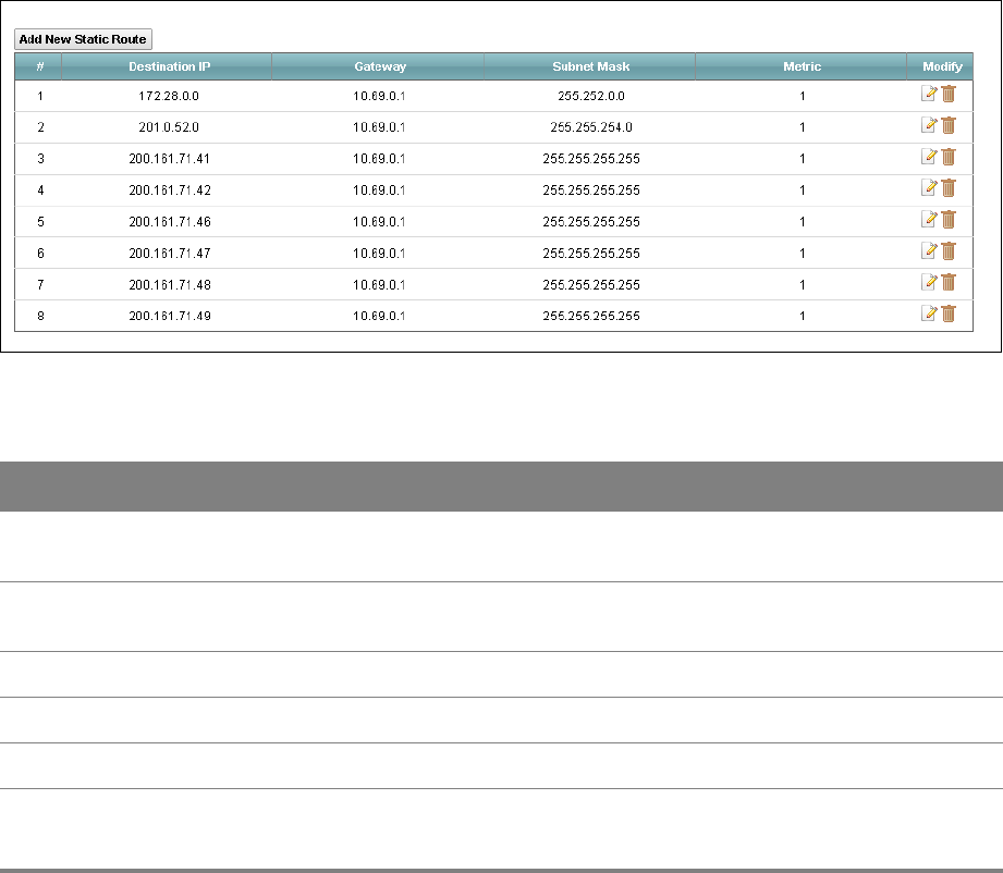
Use the Static Route screen to view and configure IP static routes on the Router. Click Network
Setting > Routing to open the Static Route screen.
Figure 32 Network Setting > Routing > Static Route
Table 24 Network Setting > Routing > Static Route
LABEL DESCRIPTION
Add New Static
Route
Click this to set up a new static route on the Router.
Destination IP This is the IP network address of the final destination. Routing is always based on
network number.
Gateway This is the IP address of the gateway.
Subnet Mask This is the IP network subnet mask of the final destination.
Metric This is the “cost” of transmission for routing purposes.
Modify Click the Edit icon to go to the screen where you can set up a static route on the Router.
Click the Delete icon to remove a static route from the Router.
Chapter 6 Static Route 53
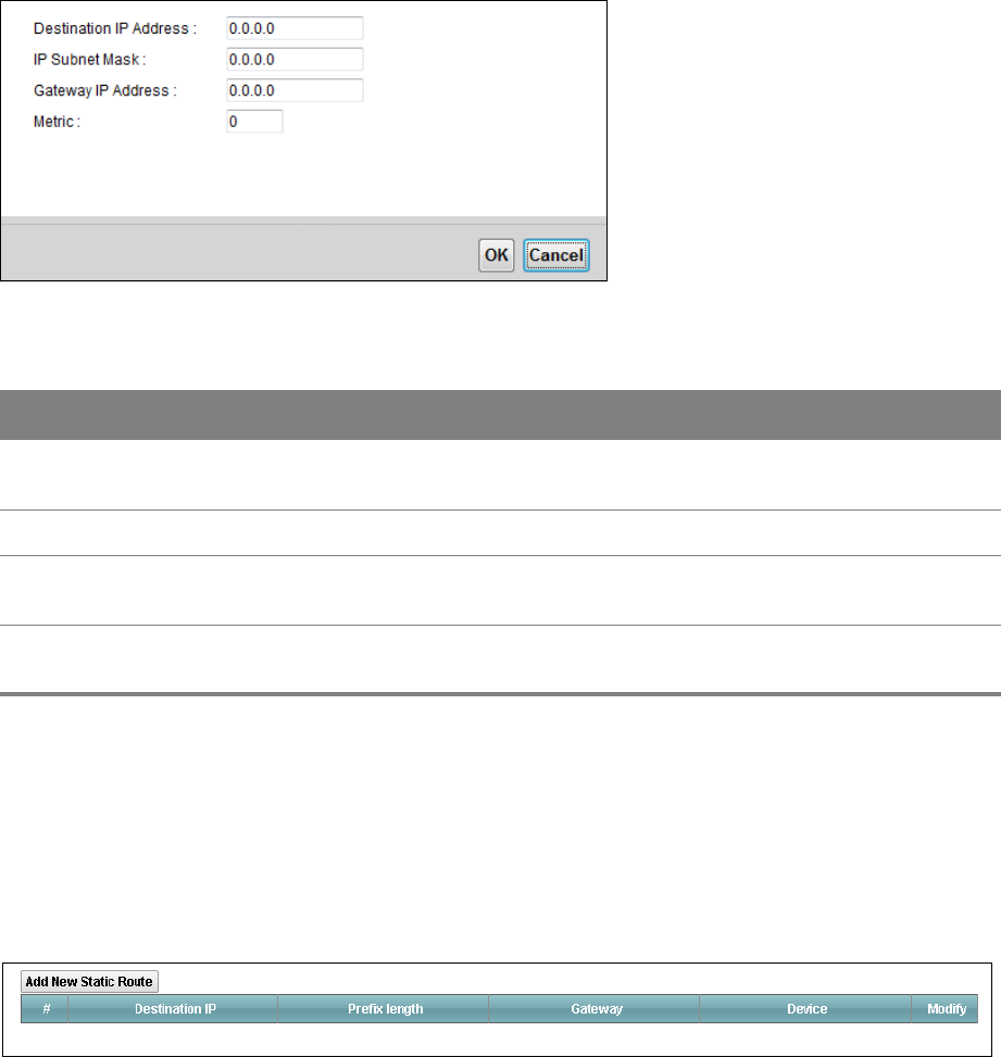
6.1.1 Add/Edit Static Route
Click Add New Static Route in the Static Route screen or click the Edit icon next to a rule. Use this
screen to configure a static route.
Figure 33 Routing > Static Route: Add/Edit
Table 25 Routing > Static Route: Add/Edit
LABEL DESCRIPTION
Destination IP
Address
Enter the IP network address of the final destination.
IP Subnet Mask Enter the IP subnet mask.
Gateway IP
Address
Enter the IP address of the next-hop gateway which helps forward packets to their
destinations.
Metric Enter the “cost” of transmission for routing purposes. IP routing uses hop count as the
measurement of cost, with a minimum of 1 for directly-connected networks.
6.2 IPv6 Static Route
Use the IPv6 Static Route screen to view the IPv6 static route rules. Click Network Setting >
Routing > IPv6 Static Route.
Figure 34 Network Setting > Routing > IPv6 Static Route

Chapter 6 Static Route 54
Table 26 Network Setting > Routing > IPv6 Static Route
LABEL DESCRIPTION
Add New Static
Route
Click this to configure a new IPv6 static route.
Destination IP This is the IP network address of the final destination.
Prefix length This is the bit number of the IPv6 subnet mask.
Gateway This is the IPv6 address of the gateway.
Device This specifies the LAN or a WAN PVC.
Modify Click the Edit icon to go to the screen where you can set up a static route on the Router.
Click the Delete icon to remove a static route from the Router.
6.2.1 Add/Edit IPv6 Static Route
Click Add New Static Route in the IPv6 Static Route screen or click the Edit icon next to a rule. Use
this screen to configure an IPv6 static route.
Figure 35 Routing > IPv6 Static Route: Add/Edit
Table 27 Routing > IPv6 Static Route: Add/Edit
LABEL DESCRIPTION
Destination IPv6
Address
Enter the IPv6 network address of the final destination.
IPv6 Prefix
Length
Enter the address prefix to specify how many most significant bits compose the
network address.
Gateway IPv6
Address
Enter the IPv6 address of the next-hop gateway which helps forward packets to their
destinations.
PVC IPv6
Address
Select the interface through which the traffic is routed.
Chapter 6 Static Route 55
6.3 The DNS Route Screen
A DNS route forwards DNS queries for a specific domain name through a specific WAN interface to
its DNS server. The DNS Route screens let you view and configure DNS routes on the Router. Click
Network Setting > Routing > DNS Route.
Figure 36 Network Setting > Routing > DNS Route
Table 28 Network Setting > Routing > DNS Route
LABEL DESCRIPTION
Add New DNS
Route
Click this to create a new DNS route.
Domain Name This is the domain name to which the DNS route applies.
Subnet Mask This parameter specifies the IP network subnet mask.
Interface This is the WAN interface through which the matched DNS request is routed.
Modify Click the Edit icon to configure a DNS route on the Router.
Click the Delete icon to remove a DNS route from the Router.
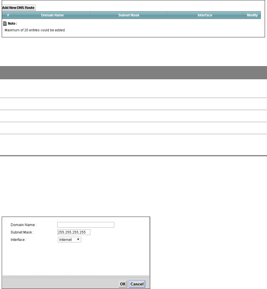
6.3.1 Add/Edit DNS Route
Click Add New DNS route in the DNS Route screen or the Edit icon next to an existing DNS route.
Use this screen to configure the required information for a DNS route.
Figure 37 Routing > DNS Route: Add/Edit
Chapter 6 Static Route 56
Table 29 Network Setting > Routing > DNS Route: Add/Edit
LABEL DESCRIPTION
Domain Name Enter the domain name you want to resolve.
You can use the wildcard character, an “*” (asterisk) as the left most part of a domain
name, such as *.example.com. The Router forwards DNS queries for any domain name
ending in example.com to the WAN interface specified in this route.
IP Subnet Mask Enter the subnet mask of the network for which to use the DNS route.
Interface Select a WAN interface through which the matched DNS query is sent. You must have
the WAN interface(s) already configured in the WAN screen.
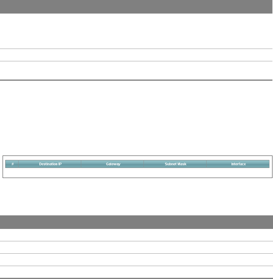
6.4 The Current Route Screen
Use the Current Route screen to view a table of the current static and dynamic routes on the
Router. Click Network Setting > Routing > Current Route.
Figure 38 Network Setting > Routing > Current Route
Table 30 Network Setting > Routing > Current Route
LABEL DESCRIPTION
Destination IP This is the IP network address of the final destination.
Gateway This is the IP address of the gateway.
Subnet Mask This is the IP network subnet mask of the final destination.
Interface This is the WAN interface through which the matched traffic is routed.
7
Chapter
Chapter 7 Quality of Service (QoS) 57
CHAPTER 7
Chapter 7 Quality of Service (QoS)
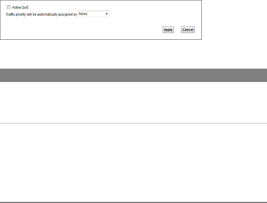
7.1 The QoS General Screen
Use this screen to enable or disable QoS, set the bandwidth, and select to have the Router
automatically assign priority to upstream traffic according to the IP precedence or packet length.
Click Network Setting > QoS to open the General screen.
Figure 39 Network Setting > QoS > General
Table 31 Network Setting > QoS > General
LABEL DESCRIPTION
Active QoS Select the check box to turn on QoS to improve your network performance.
You can give priority to traffic that the Router forwards out through the WAN interface.
Give high priority to voice and video to make them run more smoothly. Similarly, give
low priority to many large file downloads so that they do not reduce the quality of other
applications.
Traffic priority
will be
automatically
assigned by
Select how the Router assigns priorities to various upstream traffic flows.
•None: Disables auto priority mapping and has the Router put packets into the
queues according to your classification rules. Traffic which does not match any of
the classification rules is mapped into the default queue with the lowest priority.
•Ethernet Priority: Automatically assign priority based on the IEEE 802.1p priority
level.
•IP Precedence: Automatically assign priority based on the first three bits of the TOS
field in the IP header.
•Packet Length: Automatically assign priority based on the packet size. Smaller
packets get higher priority since control, signaling, VoIP, internet gaming, or other
real-time packets are usually small while larger packets are usually best effort data
packets like file transfers.
Chapter 7 Quality of Service (QoS) 58
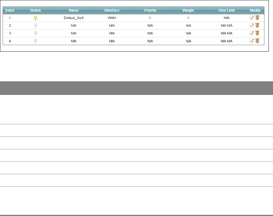
7.2 The Queue Setup Screen
Use the Queue Setup screen to configure QoS queue assignment. Click Network Setting > QoS >
Queue Setup.
Figure 40 Network Setting > QoS > Queue Setup
Table 32 Network Setting > QoS > Queue Setup
LABEL DESCRIPTION
Status This indicates whether the queue is active or not.
A yellow bulb signifies that this queue is active. A gray bulb signifies that this queue is
not active.
Name This shows the descriptive name of this queue.
Interface This shows the name of the Router’s interface through which traffic in this queue passes.
Priority This shows the priority of this queue.
Weight This shows the weight of this queue.
Rate Limit This shows the maximum transmission rate allowed for traffic in this queue.
Modify Click the Edit icon to edit the queue.
Click the Delete icon to delete an existing queue. Note that subsequent rules move up
by one when you take this action.
Chapter 7 Quality of Service (QoS) 59
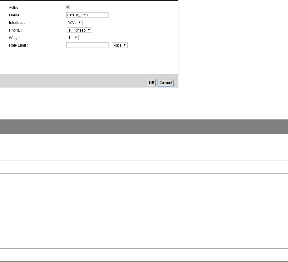
7.2.1 Edit a QoS Queue
Use this screen to configure a queue. Click the Edit icon next to a QoS queue.
Figure 41 QoS > Queue Setup: Edit
Table 33 QoS > Queue Setup: Edit
LABEL DESCRIPTION
Active Select to enable or disable this queue.
Name Enter the descriptive name of this queue.
Interface Select the interface of this queue.
Priority Select the priority level of this queue.
The lower the number, the higher the priority level. Traffic assigned to higher priority
queues gets through faster while traffic in lower priority queues is dropped if the
network is congested.
Weight Select the weight of this queue.
If two queues have the same priority level, the Router divides the bandwidth across the
queues according to their weights. Queues with larger weights get more bandwidth than
queues with smaller weights.
Rate Limit Specify the maximum transmission rate (in Kbps or %) allowed for traffic on this queue.
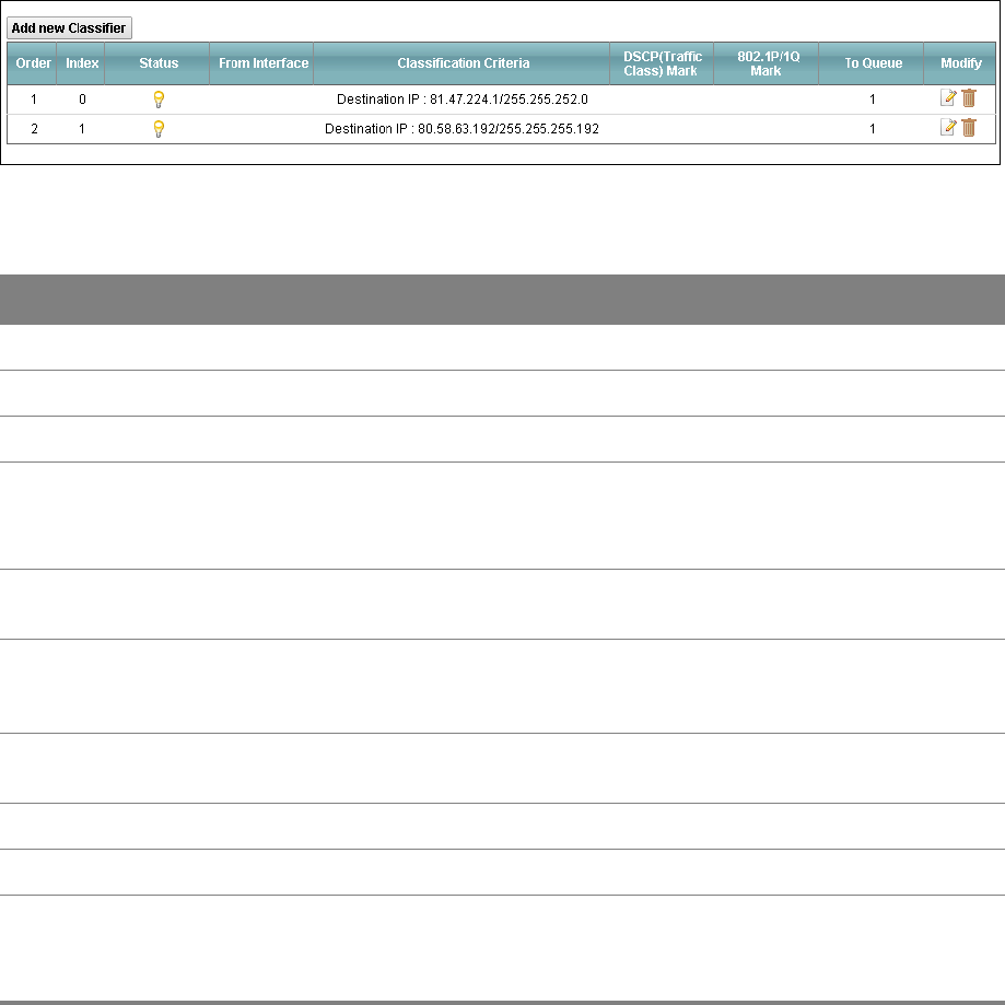
7.3 The Class Setup Screen
Use this screen to add, edit or delete QoS classifiers. A classifier groups traffic into data flows
according to specific criteria such as the source address, destination address, source port number,
destination port number or incoming interface.
You can give different priorities to traffic that the Router forwards out through the WAN interface.
Give high priority to voice and video to make them run more smoothly. Similarly, give low priority to
many large file downloads so that they do not reduce the quality of other applications.
Chapter 7 Quality of Service (QoS) 60
Click Network Setting > QoS > Class Setup to open the following screen.
Figure 42 Network Setting > QoS > Class Setup
Table 34 Network Setting > QoS > Class Setup
LABEL DESCRIPTION
Add new Classifier Click this to create a new classifier.
Order This is the order of the classifier.
Index This is the index number of the classifier.
Status This indicates whether the classifier is active or not.
A yellow bulb signifies that this classifier is active. A gray bulb signifies that this
classifier is not active.
From Interface If the classifier applies to traffic coming in through a specific interface, it displays
here.
Classification
Criteria
This shows criteria specified in this classifier, for example the interface from which
traffic of this class should come and the source MAC address of traffic that matches
this classifier.
DSCP (Traffic Class)
Mark
This is the DSCP number added to traffic of this classifier.
802.1P/1Q Mark This is the IEEE 802.1p priority level assigned to traffic of this classifier.
To Queue This is the name of the queue in which traffic of this classifier is put.
Modify Click the Edit icon to edit the classifier.
Click the Delete icon to delete an existing classifier. Note that subsequent rules
move up by one when you take this action.
Chapter 7 Quality of Service (QoS) 61
7.3.1 Add/Edit QoS Class
Click Add new Classifier in the Class Setup screen or the Edit icon next to an existing classifier to
configure it.
Figure 43 QoS > Class Setup: Add/Edit

Chapter 7 Quality of Service (QoS) 62
Table 35 QoS > Class Setup: Add/Edit
LABEL DESCRIPTION
Rule Index Select the (order) number of this rule.
Active Select to enable this classifier.
Classification Order Select an existing number for where you want to put this classifier to move the
classifier to the number you selected after clicking Apply.
Select Last to put this rule in the back of the classifier list.
Ether Type Select a predefined application to configure a class for the matched traffic.
If you select IPv4 (0x0800), you also need to configure source or destination MAC
address, IP address, DHCP options, DSCP value or the protocol type.
If you select ARP (0x0806) (available when you set Interface to From LAN), you can
configure source or destination MAC addresses.
If you select 802.1Q (0x8100) (available when you set Interface to From LAN) you
can configure an 802.1p priority level.
Interface Select whether to apply this class to traffic from the LAN or from the WAN.
To Queue Select a queue to apply to this class (available when you set Interface to From
WAN).
You should have configured a queue in the Queue Setup screen already.
From Interface Select the interface from which the traffic class comes.
IP Address Select the check box and enter the source IP address in dotted decimal notation. A
blank source IP address means any source IP address.
IP Subnet Mask Enter the source subnet mask.
Exclude Select this option to exclude the packets that match the specified criteria from this
classifier.
Port Range If you select TCP or UDP in the IP Protocol field, select the check box and enter the
port number(s) of the source.
Exclude Select this option to exclude the packets that match the specified criteria from this
classifier.
MAC Address Select the check box and enter the source MAC address of the packet.
MAC Mask Type the mask for the specified MAC address to determine which bits a packet’s
MAC address should match.
Exclude Select this option to exclude the packets that match the specified criteria from this
classifier.
IP Address Select the check box and enter the destination IP address in dotted decimal
notation. A blank source IP address means any source IP address.
IP Subnet Mask Enter the destination subnet mask.

Chapter 7 Quality of Service (QoS) 63
Port Range If you select TCP or UDP in the IP Protocol field, select the check box and enter the
port number(s) of the source.
MAC Address Select the check box and enter the destination MAC address of the packet.
MAC Mask Type the mask for the specified MAC address to determine which bits a packet’s
MAC address should match.
Exclude Select this option to exclude the packets that match the specified criteria from this
classifier.
Service Select the service classification of the traffic (FTP or SIP).
IP Protocol This field is available only when you select IPv4 (0x0800) in the Ether Type field.
Select this option and select the protocol (service type) from TCP or UDP. If you
select User defined, enter the protocol (service type) number.
TCP ACK This field is available only when you select IPv4 (0x0800) in the Ether Type field.
If you select this option, the matched TCP packets must contain the ACK
(Acknowledge) flag.
DHCP This field is available only when you select IPv4 (0x0800) in the Ether Type field, and
UDP in the IP Protocol field.
Select this option and select a DHCP option.
If you select Vendor Class ID (DHCP Option 60), enter the Class ID of the matched
traffic, such as the type of the hardware or firmware.
If you select User Class ID (DHCP Option 77), enter the User Class Data, which is a
string that identifies the user’s category or application type in the matched DHCP
packets.
If you select ClientID (DHCP Option 61), enter the Type of the matched traffic and
Client ID of the DHCP client.
If you select VendorSpecificIntro (DHCP Option 125), enter the Enterprise
Number of the software of the matched traffic and Vendor Class Data used by all
the DHCP clients.
Packet Length This field is available only when you select IPv4 (0x0800) in the Ether Type field.
Select this option and enter the minimum and maximum packet length (from 46 to
1504) in the fields provided.
IPP/DS Field Select IPP/TOS to specify an IP precedence range and type of services.
Select DSCP to specify a DiffServ Code Point (DSCP) range.
IP Precedence
Range Enter a range from 0 to 7 for IP precedence. 0 is the lowest priority and 7 is the
highest.
Type of Service Select a type of service from the drop-down list box.
Available options are: Normal service, Minimize delay, Maximize throughput,
Maximize reliability and Minimize monetary cost.
Table 35 QoS > Class Setup: Add/Edit (continued)
LABEL DESCRIPTION

Chapter 7 Quality of Service (QoS) 64
DSCP Range (0 ~
63) Select this option and specify a DSCP (DiffServ Code Point) number between 0 and
63 in the field provided.
802.1P Select this option and select a priority level (between 0 and 7) from the drop-down
list box.
"0" is the lowest priority level and "7" is the highest.
VLAN ID Select this option and enter the source VLAN ID in this field.
Exclude Select this option to exclude the packets that match the specified criteria from this
classifier.
Forward To Select the interface through which traffic that matches the rule is forwarded out. If
you select Unchange, the Router forwards traffic of this class according to the
default routing table.
If traffic of this class comes from a WAN interface and is in a queue that forwards
traffic through the LAN/WLAN interface, the Router ignores the setting here.
IPP/DS Field Select IPP/TOS to specify an IP precedence range and type of services.
Select DSCP to specify a DiffServ Code Point (DSCP) range.
IP Precedence
MarkEnter a range from 0 to 7 to re-assign IP precedence to matched traffic. 0 is the
lowest priority and 7 is the highest.
Type Of Service
MarkSelect a type of service to re-assign the priority level to matched traffic.
DSCP Mark(0~63) This field is available only when you select IPv4 (0x0800) in the Ether Type field.
If you select Mark, enter a DSCP value with which the Router replaces the DSCP field
in the packets.
If you select Unchange, the Router keep the DSCP field in the packets.
802.1Q Tag If you select Remark, select a priority level (in the Ethernet Priority field) and enter
a VLAN ID number (in the VLAN ID field) with which the Router replaces the IEEE
802.1p priority field and VLAN ID of the frames.
If you select Remove, the Router deletes the VLAN ID of the frames before
forwarding them out.
If you select Add, the Router treat all matched traffic untagged and add a second
priority level and VLAN ID that you specify in the Ethernet Priority and VLAN ID
fields.
If you select Same, the Router keep the Ethernet Priority and VLAN ID in the packets.
To configure the Ethernet Priority, you can either select a priority number in the first
drop-down list box (7 is the highest and 0 is the lowest priority) or select an
application from the second drop-down list box which automatically maps to the
corresponding priority number. (Key Net Traffic: 7; Voice: 6; Video: 5; IGMP: 4; Key
Data: 3)
VLAN ID Select this option and enter the source VLAN ID in this field.
Table 35 QoS > Class Setup: Add/Edit (continued)
LABEL DESCRIPTION
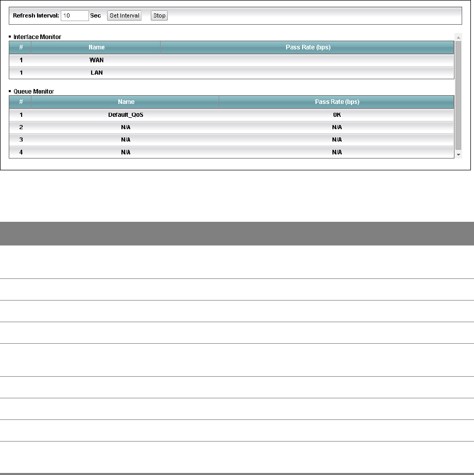
Chapter 7 Quality of Service (QoS) 65
7.4 The QoS Monitor Screen
To view the Router’s QoS packet statistics, click Network Setting > QoS > Monitor.
Figure 44 Network Setting > QoS > Monitor
Table 36 Network Setting > QoS > Monitor
LABEL DESCRIPTION
Refresh Interval Enter how often you want the Router to update this screen and click Set Interval.
Click Stop to stop refreshing statistics.
Interface Monitor
#This is the index number of the entry.
Name This shows the name of the interface on the Router.
Pass Rate (bps) This shows how much traffic (bps) forwarded to this interface are transmitted
successfully.
Queue Monitor
#This is the index number of the entry.
Name This shows the name of the queue.
Pass Rate (bps) This shows how much traffic (bps) assigned to this queue are transmitted
successfully.
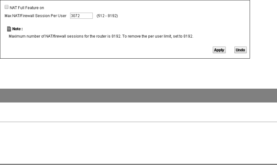
8
Chapter
Chapter 8 Network Address Translation (NAT) 66
CHAPTER 8
Chapter 8 Network Address Translation
(NAT)
8.1 The General Screen
Click Network Setting > NAT to open the General screen. You can limit the number of concurrent
NAT sessions each client can use.
Figure 45 Network Setting > NAT > General
Table 37 Network Setting > NAT > General
LABEL DESCRIPTION
NAT Full
Feature on
Select this check box if you have multiple public WAN IP addresses for your Router.
Max NAT/
Firewall
Session Per
User
Use this field to set a common limit to the number of concurrent NAT sessions each client
computer can have.
If only a few clients use peer to peer applications, you can raise this number to improve
their performance. With heavy peer to peer application use, lower this number to ensure
no single client uses too many of the available NAT sessions.
8.2 The Port Forwarding Screen
Use the Port Forwarding screen to forward incoming service requests to the servers on your local
network.
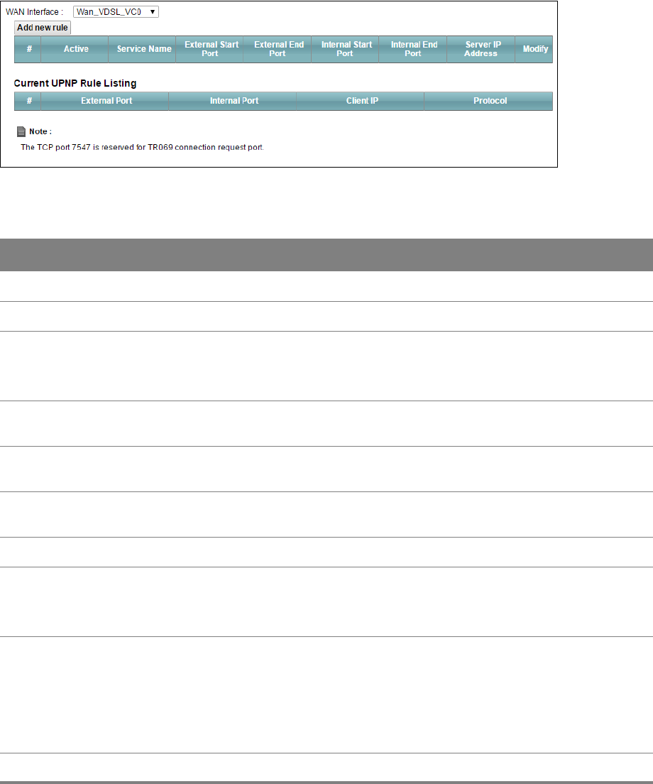
Chapter 8 Network Address Translation (NAT) 67
8.2.1 The Port Forwarding Screen
Click Network Setting > NAT to open the Port Forwarding screen.
Figure 46 Network Setting > NAT > Port Forwarding
Table 38 Network Setting > NAT > Port Forwarding
LABEL DESCRIPTION
WAN Interface Select the WAN interface for which to configure NAT port forwarding rules.
Add new rule Click this to add a new port forwarding rule.
Active This field indicates whether the rule is active or not.
A yellow bulb signifies that this rule is active. A gray bulb signifies that this rule is not
active.
Service Name This is the service’s name. This shows User Defined if you manually added a service.
You can change this by clicking the edit icon.
External Start/End
Port
This is the first/last external port number that identifies a service.
Internal Start/End
Port
This is the first/last internal port number that identifies a service.
Server IP Address This is the server’s IP address.
Modify Click the Edit icon to edit the port forwarding rule.
Click the Delete icon to delete an existing port forwarding rule. Note that subsequent
address mapping rules move up by one when you take this action.
Current UPNP
Rule Listing
Universal Plug and Play (UPnP) is a distributed, open networking standard that uses
TCP/IP for simple peer-to-peer network connectivity between devices. A UPnP device
can dynamically join a network, obtain an IP address, convey its capabilities and learn
about other devices on the network. In turn, a device can leave a network smoothly
and automatically when it is no longer in use.
These are the rules the Router has created using UPnP.
External Port This is the external port number that identifies a service.
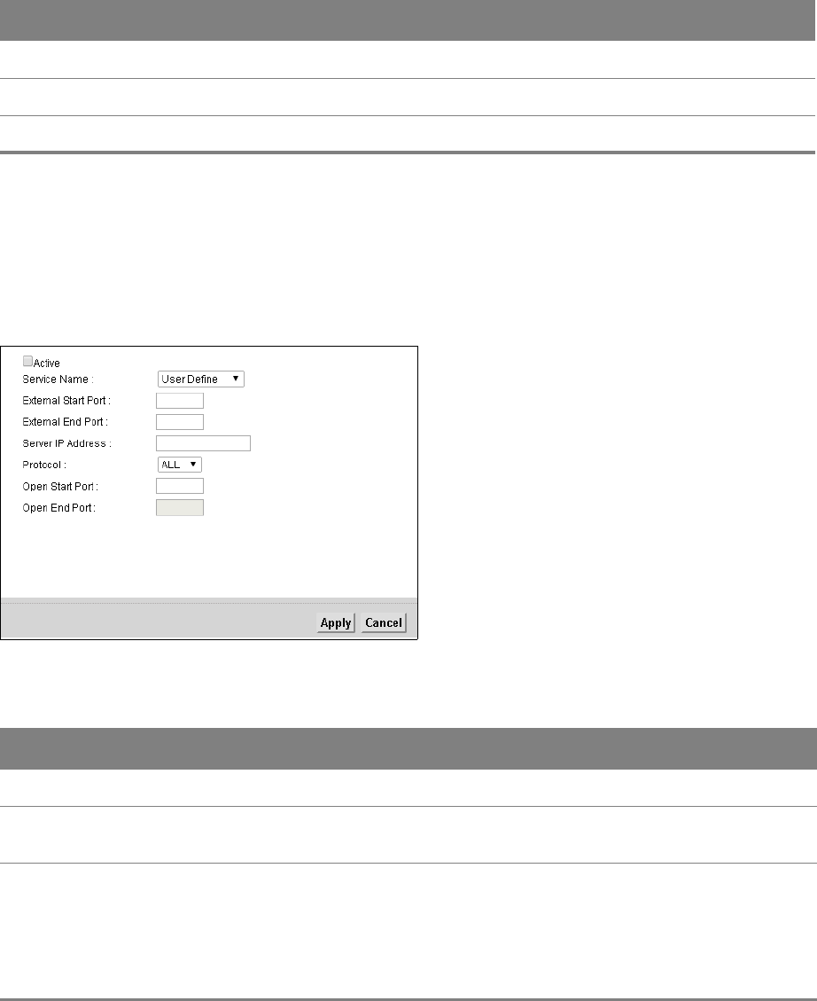
Chapter 8 Network Address Translation (NAT) 68
8.2.2 The Port Forwarding Add/Edit Screen
This screen lets you create or edit a port forwarding rule. Click Add new rule in the Port
Forwarding screen or the Edit icon next to an existing rule.
Figure 47 NAT > Port Forwarding: Add/Edit
Internal Port This is the internal port number that identifies a service.
Client IP This is the IP address of the device for which the Router created the UPnP rule.
Protocol This is the protocol of the traffic for which the Router created the UPnP rule.
Table 38 Network Setting > NAT > Port Forwarding (continued)
LABEL DESCRIPTION
Table 39 NAT > Port Forwarding: Add/Edit
LABEL DESCRIPTION
Active Select or clear this field to turn the port forwarding rule on or off.
Service Name Select a service to forward or select User Defined and enter a name in the field to the
right.
External Start
Port
Configure this for a user-defined entry. Enter the original destination port for the
packets.
To forward only one port, enter the port number again in the External End Port field.
To forward a series of ports, enter the start port number here and the end port number
in the External End Port field.
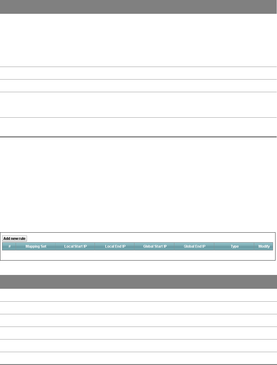
Chapter 8 Network Address Translation (NAT) 69
8.3 The Address Mapping Screen
Ordering your rules is important because the Router applies the rules in the order that you specify.
When a rule matches the current packet, the Router takes the corresponding action and the
remaining rules are ignored.
This screen is available only when you select NAT Full Feature on in the General screen. To change
your Router’s address mapping settings, click Network Setting > NAT > Address Mapping.
Network Setting > NAT > Address Mapping
External End Port Configure this for a user-defined entry. Enter the last port of the original destination
port range.
To forward only one port, enter the port number in the External Start Port field above
and then enter it again in this field.
To forward a series of ports, enter the last port number in a series that begins with the
port number in the External Start Port field above.
Server IP Address Enter the inside IP address of the virtual server here.
Protocol Select the protocol supported by this virtual server. Choices are TCP, UDP, or TCP/UDP.
Open Start Port Configure this for a user-defined entry. This shows the port number to which you want
the Router to translate the incoming port. For a range of ports, enter the first number
of the range to which you want the incoming ports translated.
Open End Port Configure this for a user-defined entry. This shows the last port of the translated port
range.
Table 39 NAT > Port Forwarding: Add/Edit (continued)
LABEL DESCRIPTION
Table 40 Network > NAT > Address Mapping
LABEL DESCRIPTION
Add new rule Click this to add a new address mapping rule.
Mapping Set This is the index number of the address mapping set.
Local Start IP This is the starting Inside Local IP Address (ILA).
Local End IP This is the end Inside Local IP Address (ILA).
Global Start IP This is the starting Inside Global IP Address (IGA).
Global End IP This is the ending Inside Global IP Address (IGA).
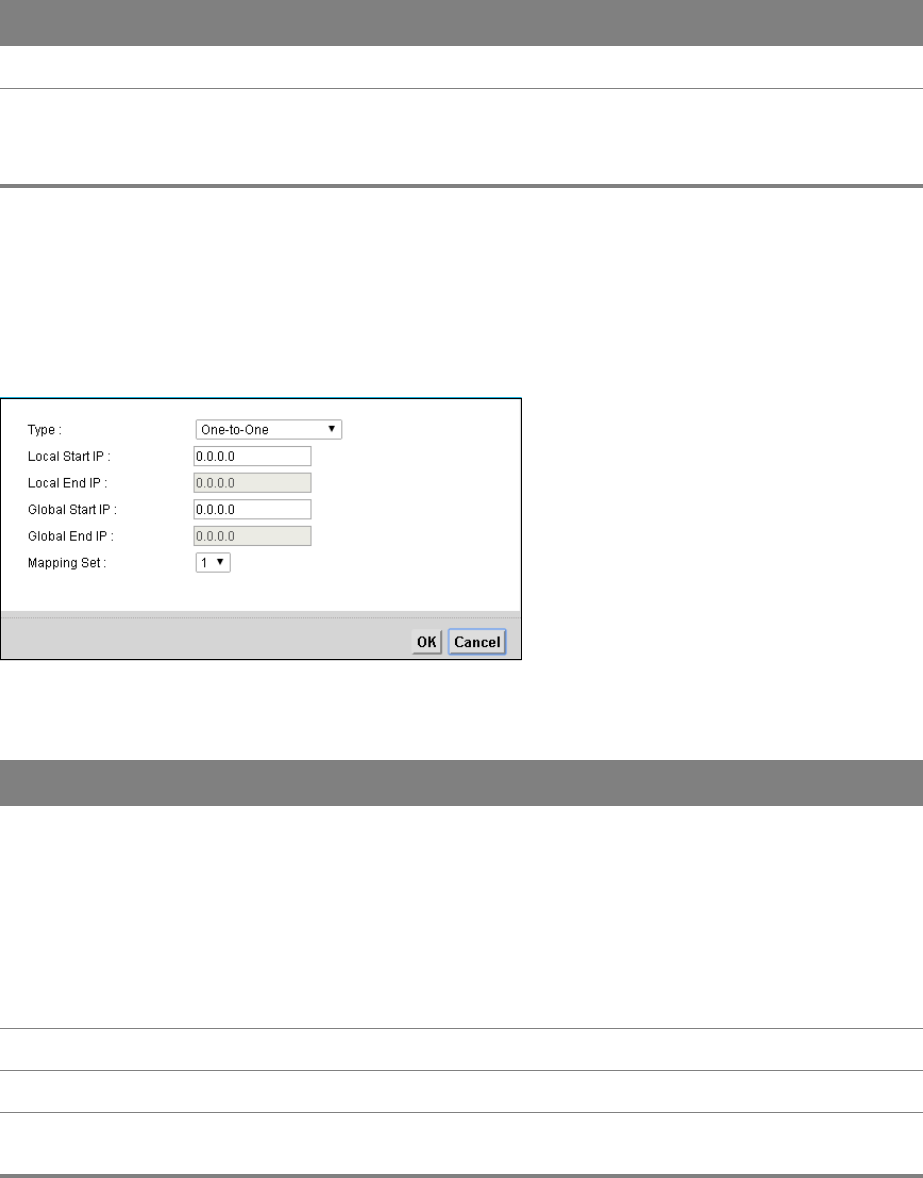
Chapter 8 Network Address Translation (NAT) 70
8.3.1 The Address Mapping Rule Edit Screen
Use this screen to edit an address mapping rule. Click the rule’s edit icon in the Address Mapping
screen to display the screen shown next.
Figure 48 NAT > Address Mapping: Edit
Type This is the port mapping type.
Modify Click the edit icon to go to the screen where you can edit the address mapping rule.
Click the delete icon to delete an existing address mapping rule. Note that subsequent
address mapping rules move up by one when you take this action.
Table 40 Network > NAT > Address Mapping (continued)
LABEL DESCRIPTION
Figure 49 NAT > Address Mapping: Edit
LABEL DESCRIPTION
Type Choose the port mapping type from one of the following.
One-to-One: maps one local IP address to one global IP address. Note that port
numbers do not change for One-to-one NAT mapping type.
Many-to-One: maps multiple local IP addresses to one global IP address.
Many-to-Many: maps multiple local IP addresses to shared global IP addresses.
One-to-Many (Server): allows you to specify inside servers of different services
behind the NAT to be accessible to the outside world.
Local Start IP Enter the starting local IP address (ILA).
Local End IP Enter the ending local IP address (ILA).
Global Start IP Enter the starting global IP address (IGA). Enter 0.0.0.0 here if you have a dynamic IP
address from your ISP.
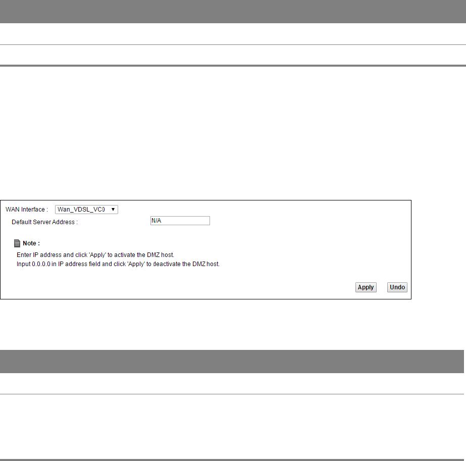
Chapter 8 Network Address Translation (NAT) 71
8.4 The DMZ Screen
Click Network Setting > NAT > DMZ to open the DMZ screen. Use this screen to specify the IP
address of a default server to receive packets from ports not specified in the Port Forwarding
screen.
Figure 50 Network Setting > NAT > DMZ
Table 41 Network Setting > NAT > DMZ
LABEL DESCRIPTION
WAN Interface Select the WAN interface for which to configure a default server.
Default Server
Address
Enter the IP address of the default server which receives packets from ports that are not
specified in the Port Forwarding screen.
Note: If you do not assign a default server, the Router discards all packets received for
ports not specified in the virtual server configuration.
8.5 The ALG Screen
Click Network Setting > NAT > ALG to open the ALG screen. Use this screen to enable and disable
the NAT Application Layer Gateway (ALG) in the Router.
Global End IP This is the ending global IP address (IGA).
Mapping Set Select the index number of the address mapping set.
Figure 49 NAT > Address Mapping: Edit (continued)
LABEL DESCRIPTION
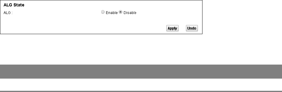
Chapter 8 Network Address Translation (NAT) 72
The SIP ALG allows SIP calls to pass through NAT by examining and translating IP addresses
embedded in the data stream. When the Router registers with the SIP register server, the SIP ALG
translates the Router’s private IP address inside the SIP data stream to a public IP address. You do
not need to use STUN or an outbound proxy if you enable the SIP ALG.
Figure 51 Network Setting > NAT > ALG
Table 42 Network Setting > NAT > ALG
LABEL DESCRIPTION
ALG Enable this to make sure SIP (VoIP) works correctly with port-forwarding.
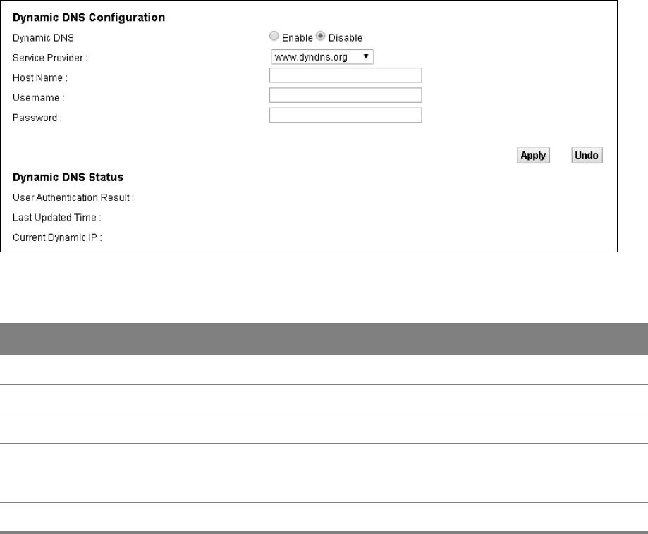
9
Chapter
Chapter 9 Dynamic DNS 73
CHAPTER 9
Chapter 9 Dynamic DNS
9.1 The Dynamic DNS Screen
Dynamic DNS allows you to update your current dynamic IP address with one or many dynamic
DNS services. You need to have registered a dynamic DNS account with www.dyndns.org. This is for
people with a dynamic IP from their ISP or DHCP server that would still like to have a domain name.
Use the Dynamic DNS screen to enable DDNS and configure the DDNS settings on the Router. Click
Network Setting > Dynamic DNS.
Figure 52 Network Setting > Dynamic DNS
Table 43 Network Setting > Dynamic DNS
LABEL DESCRIPTION
Dynamic DNS Select Enable to use dynamic DNS.
Service Provider Select the name of your Dynamic DNS service provider.
Host Name Type the domain name assigned to your Router by your Dynamic DNS provider.
Username Type your user name for the Dynamic DNS service provider.
Password Type your password for the Dynamic DNS service provider.
Apply Click Apply to save your changes.

Chapter 9 Dynamic DNS 74
Undo Click Undo to restore your previously saved settings.
Dynamic DNS Status
User
Authentication
Result
This field displays the results of the Router’s attempt to authenticate with the Dynamic
DNS service provider.
Last Updated
Time
This field displays when the Router last updated its WAN IP address to the Dynamic
DNS service provider.
Current Dynamic
IP
This field displays the Router’s current WAN IP address.
Table 43 Network Setting > Dynamic DNS (continued)
LABEL DESCRIPTION
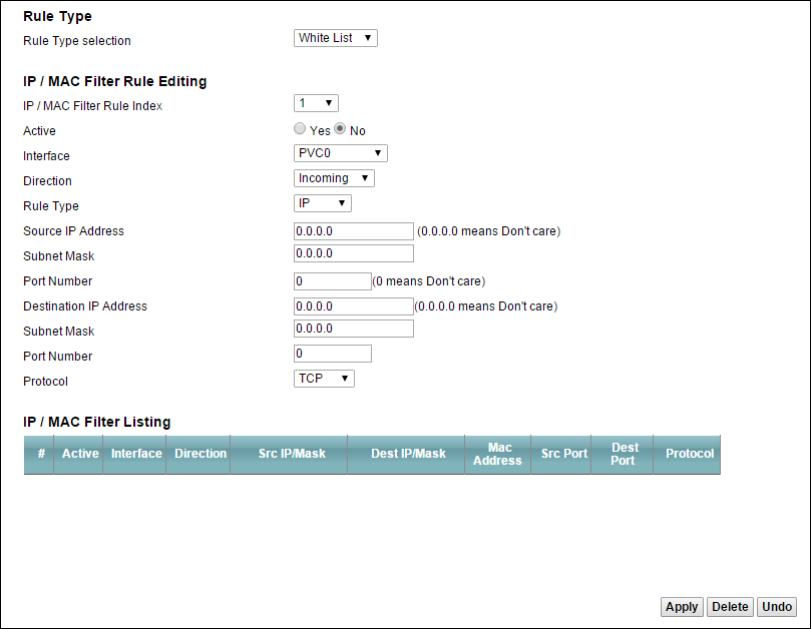
10
Chapter
Chapter 10 Filter 75
CHAPTER 10
Chapter 10 Filter
10.1 The IP/MAC Filter Screen
Use the IP/MAC Filter screen to create and apply IP/MAC filters. Click Security > Filter to show the
IP/MAC Filter screen.
Figure 53 Security > Filter > IP/MAC Filter

Chapter 10 Filter 76
Table 44 Security > Filter > IP/MAC Filter
LABEL DESCRIPTION
Rule Type selection Select White List to create a filter rule that allows traffic.
Select Black List to create a filter rule that blocks traffic.
IP/MAC Filter Rule Index Select the index number of the filter rule.
Active Use this field to enable or disable the rule.
Interface Select the interface to which to apply the filter.
Direction Apply the filter to Incoming or Outgoing traffic direction.
Rule Type Select IP to filter traffic by IP addresses.
Select MAC to filter traffic by MAC address.
Source IP Address Enter the source IP address of the packets you wish to filter.
Subnet Mask Enter the IP subnet mask for the source IP address
Port Number Enter the source port of the packets that you wish to filter.
Destination IP Address Enter the destination IP address of the packets you wish to filter.
Subnet Mask Enter the IP subnet mask for the destination IP address.
Port Number Enter the destination port of the packets that you wish to filter.
Protocol Select ICMP, TCP or UDP for the upper layer protocol.
Source MAC Address This field is only available when you select MAC in the Rule Type field.
Enter the MAC address of the packets you wish to filter.
Active This field shows whether the rule is activated.
Interface This field shows the interface to which the filter rule applies.
Direction The filter rule applies to this traffic direction.
Src IP/Mask This is the source IP address and subnet mask when you select IP as the rule
type.
This is the MAC address when you select MAC as the rule type.
Dest IP/Mask This is the destination IP address and subnet mask.
MAC Address For a MAC filter rule this field shows the MAC address of the packets to filter.
Src Port This is the source port number.
Dest Port This is the destination port number.
Protocol This is the upper layer protocol.
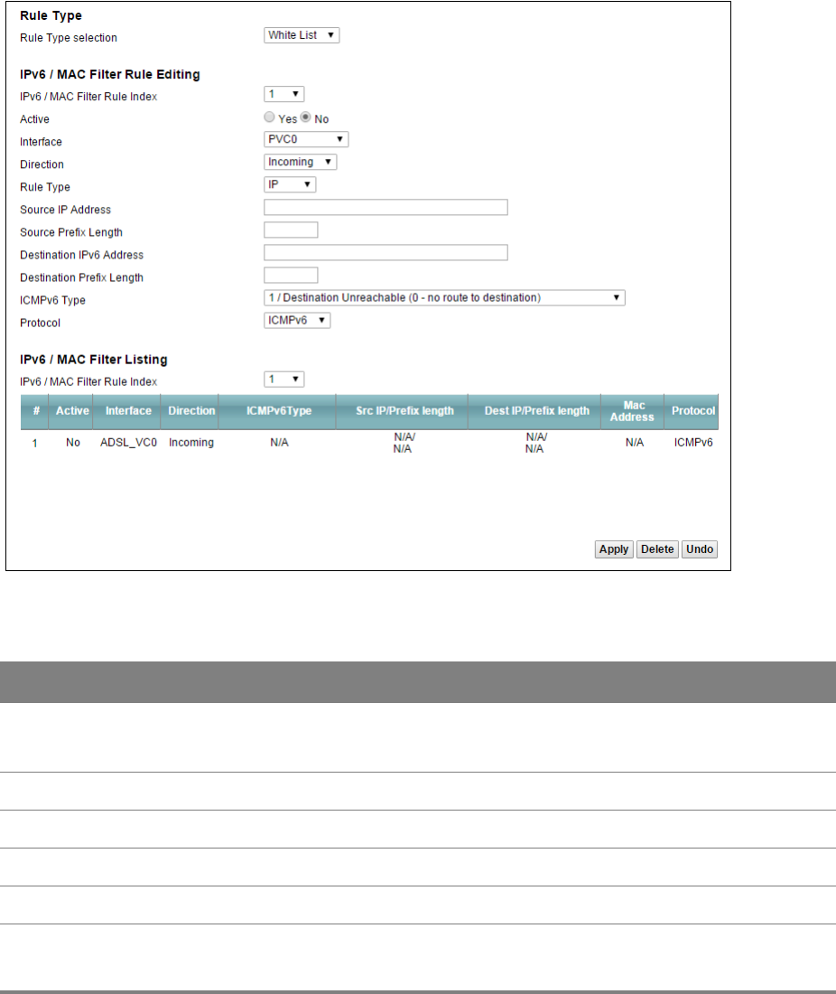
Chapter 10 Filter 77
10.2 The IPv6/MAC Filter Screen
Use the IPv6/MAC Filter screen to create and apply IPv6 address /MAC filters. Click Security > Filter
>IPv6/MAC Filter.
Figure 54 Security > Filter > IPv6/MAC Filter
Table 45 Security > Filter > IPv6/MAC Filter
LABEL DESCRIPTION
Rule Type selection Select White List to create a filter rule that allows traffic.
Select Black List to create a filter rule that blocks traffic.
IPv6/MAC Filter Rule Index Select the index number of the filter rule.
Active Use this field to enable or disable the rule.
Interface Select the interface to which to apply the filter.
Direction Apply the filter to Incoming or Outgoing traffic direction.
Rule Type Select IP to filter traffic by IP addresses.
Select MAC to filter traffic by MAC address.

Chapter 10 Filter 78
Source IP Address Enter the source IP address of the packets you wish to filter.
Source Prefix Length Enter the prefix length for the source IPv6 address.
Destination IPv6 Address Enter the destination IPv6 address of the packets you wish to filter.
Destination Prefix Length Enter the prefix length for the destination IPv6 address.
ICMPv6 Type Select one of the ICMPv6 message types to filter.
Protocol This is the (upper layer) protocol that defines the service to which this rule
applies. By default it is ICMPv6.
Source MAC Address This field is only available when you select MAC in the Rule Type field.
Enter the MAC address of the packets you wish to filter.
IPv6 / MAC Filter Rule Index Select the index number of the filter set.
Active This field shows whether the rule is activated.
Interface This field shows the interface to which the filter rule applies.
Direction The filter rule applies to this traffic direction.
ICMPv6Type This is the ICMPv6 message type to filter.
Src IP/Prefix length This is the source IPv6 address and prefix length.
Dest IP/Prefix length This displays the destination IPv6 address and prefix length.
MAC Address This is the MAC address of the packets being filtered.
Protocol This is the (upper layer) protocol that defines the service to which this rule
applies.
Table 45 Security > Filter > IPv6/MAC Filter (continued)
LABEL DESCRIPTION
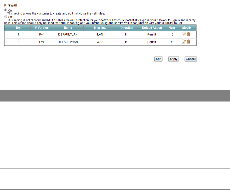
11
Chapter
Chapter 11 Firewall 79
CHAPTER 11
Chapter 11 Firewall
11.1 Firewall General Screen
Use this screen to enable or disable the firewall filters on the Router. Each filter may include
multiple firewall rules which you can create in the Rules screen (see Section 11.2 on page 80). You
can also edit existing filters or create new ones. Click Security > Firewall to open the General
screen.
Figure 55 Security > Firewall > General
Table 46 Security > Firewall > General
LABEL DESCRIPTION
On Select this to enable the firewall filter on the Router.
Off Select this to disable the firewall filter on the Router. This setting is not recommended. It
disables firewall protection for your network and could potentially expose your network to
significant security risks. This option should only be used for troubleshooting or if you use
another firewall in conjunction with your router.
Modify Click the edit icon to go to the screen where you can edit an existing filter.
Click the delete icon to delete an existing filter.
Add Click this to add a new default action that the firewall takes.
Apply Click this to save your changes.
Cancel Click this to restore your previously saved settings.
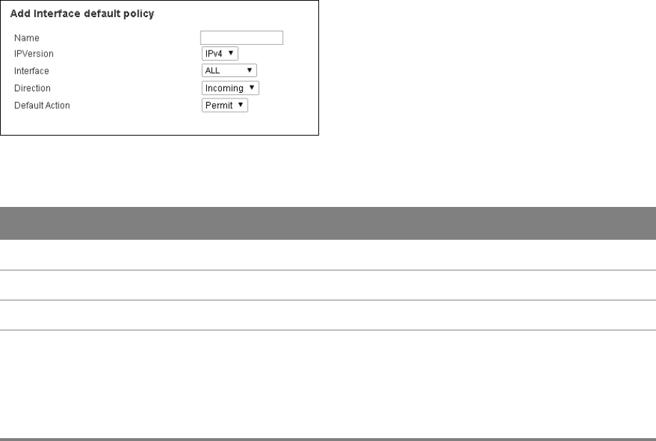
Chapter 11 Firewall 80
11.1.1 Add/Edit Interface Default Policy Screen
Use this screen to edit existing firewall filters or create new ones. Click the edit icon next to an
existing firewall filter or click the Add button in the General screen.
Figure 56 Firewall > General: Add/Edit
Table 47 Firewall > General: Add/Edit
LABEL DESCRIPTION
Name Enter a descriptive name for this firewall filter.
IPVersion Select the IP version for this firewall filter.
Packet Direction Select the direction of traffic which applies to this firewall filter.
Default Action Select the default action that the firewall is to take on packets that are traveling in the
selected direction and do not match any of the firewall filters.
Select Permit to allow the passage of the packets.
Select Drop to silently discard the packets without sending a TCP reset packet or an
ICMP destination-unreachable message to the sender.
11.2 Rules Screen
The Rules screen displays a list of the configured firewall rules. Note the order in which the rules
are listed. Click Security > Firewall > Rules.
Chapter 11 Firewall 81
The ordering of your rules is very important as rules are applied in turn.
Figure 57 Security > Firewall > Rules
Table 48 Security > Firewall > Rules
LABEL DESCRIPTION
Packet Direction Select an existing firewall filter that has already been created in the General
screen. The existing rules included in this filter will be shown in this table and you
can add a new firewall rule to this filter.
Create a new rule
after rule number
Select an index number and click Add to add a new firewall rule after the selected
index number. For example, if you select “6”, your new rule becomes number 7 and
the previous rule 7 (if there is one) becomes rule 8.
The following read-only fields summarize the rules you have created that apply to
traffic traveling in the selected packet direction. The firewall rules that you
configure (summarized below) take priority over the general firewall action settings
in the General screen.
No. This is your firewall rule number. The ordering of your rules is important as rules
are applied in turn.
Active This displays whether a firewall is turned on or not. Select the check box to enable
the rule. Clear the check box to disable the rule.
Name This displays the name of the firewall rule.
Interface This displays the source interface to which this firewall rule applies. This is the
interface through which the traffic entered the Router.
Destination IP
Address
This displays the destination addresses or ranges of addresses to which this
firewall rule applies.
Filter Criteria This displays the filter criteria set for this firewall rule.

Chapter 11 Firewall 82
Action This field displays whether the firewall silently discards packets (Drop) or allows
the passage of packets (Permit).
Modify Click the Edit icon to go to the screen where you can edit the rule.
Click the Remove icon to delete an existing firewall rule. A window displays asking
you to confirm that you want to delete the firewall rule. Note that subsequent
firewall rules move up by one when you take this action.
Table 48 Security > Firewall > Rules (continued)
LABEL DESCRIPTION
Chapter 11 Firewall 83
11.2.1 Rules Edit Screen
Use this screen to configure firewall rules. In the Rules screen, select an index number and click a
rule’s Edit icon.
Figure 58 Firewall > Rules: Edit
Table 49 Firewall > Rules: Edit
LABEL DESCRIPTION
Active Select this option to enable this firewall rule.
Rule Name If you want to select an exiting service, choose Select a Service and find the service
to which this rule applies to in the drop-down list box.
If you want to manually configure a service that is not in the list, choose Custom
Service. Enter the name of the service and select its protocol in the Protocol field.
If you select ICMP as your protocol, select the ICMP type in the ICMP (Type-code)
field below.
Source IP Address Enter the source IP address.
Source Subnet Mask Enter the source subnet mask.
Source Port Enter a single source port or a port range.
Destination IP
Address
Enter the destination IP address.
Destination Subnet
Mask
Enter the destination subnet mask.
Chapter 11 Firewall 84
11.3 DoS Screen
Use the DoS screen to enable DoS protection. Click Security > Firewall > DoS.
Figure 59 Security > Firewall > DoS
Table 50 Security > Firewall > Dos
LABEL DESCRIPTION
Denial of
Services
Enable this to protect against DoS attacks. The Router will drop sessions that surpass
maximum thresholds.
Apply Click this to save your changes.
Undo Click this to restore your previously saved settings.
Advanced Click this to go to a screen to specify maximum thresholds at which the Router will start
dropping sessions.
Destination Port Enter a single destination port or a port range.
Action for Matched
Packets
Select whether to discard (Drop), deny and send an ICMP destination-unreachable
message to the sender of (Reject) or allow the passage of (Permit) packets that
match this rule.
Table 49 Firewall > Rules: Edit (continued)
LABEL DESCRIPTION
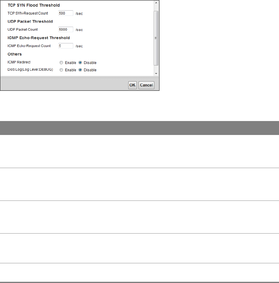
Chapter 11 Firewall 85
11.3.1 The DoS Advanced Screen
Click Security > Firewall > DoS > Advanced to display the following screen.
Figure 60 Firewall > DoS > Advanced
Table 51 Firewall > DoS > Advanced
LABEL DESCRIPTION
TCP SYN-Request
Count
This is the rate of new TCP half-open sessions per second that causes the firewall to
start deleting half-open sessions. When the rate of new connection attempts rises
above this number, the Router deletes half-open sessions as required to
accommodate new connection attempts.
UDP Packet Count This is the rate of new UDP half-open sessions per second that causes the firewall
to start deleting half-open sessions. When the rate of new connection attempts
rises above this number, the Router deletes half-open sessions as required to
accommodate new connection attempts.
ICMP Echo-Request
Count
This is the rate of new ICMP Echo-Request half-open sessions per second that
causes the firewall to start deleting half-open sessions. When the rate of new
connection attempts rises above this number, the Router deletes half-open
sessions as required to accommodate new connection attempts.
ICMP Redirect Select Enable to monitor for and block ICMP redirect attacks.
An ICMP redirect attack is one where forged ICMP redirect messages can force the
client device to route packets for certain connections through an attacker’s host.
DoS Log(Log Level:
DEBUG)
Select Enable to log DoS attacks.
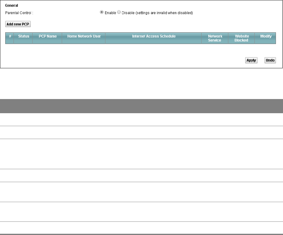
12
Chapter
Chapter 12 Parental Control 86
CHAPTER 12
Chapter 12 Parental Control
12.1 The Parental Control Screen
Parental control allows you to block web sites with the specific URL. You can also define time
periods and days during which the Router performs parental control on a specific user.
Use the Parental Control screen to enable parental control, view the parental control rules and
schedules. Click Security > Parental Control.
Figure 61 Security > Parental Control
Table 52 Security > Parental Control
LABEL DESCRIPTION
Parental Control Select Enable to activate parental control.
Add new PCP Click this if you want to configure a new parental control rule.
Status This indicates whether the rule is active or not.
A yellow bulb signifies that this rule is active. A gray bulb signifies that this rule is not
active.
PCP Name This shows the name of the rule.
Home Network
User
This shows the MAC address of the LAN user’s computer to which this rule applies.
Internet Access
Schedule
This shows the days and time on which parental control is enabled.
Network Service This shows whether the network service is configured. If not, None will be shown.

Chapter 12 Parental Control 87
Website Blocked This shows whether the website block is configured. If not, None will be shown.
Modify Click the Edit icon to go to the screen where you can edit the rule.
Click the Delete icon to delete an existing rule.
Table 52 Security > Parental Control (continued)
LABEL DESCRIPTION
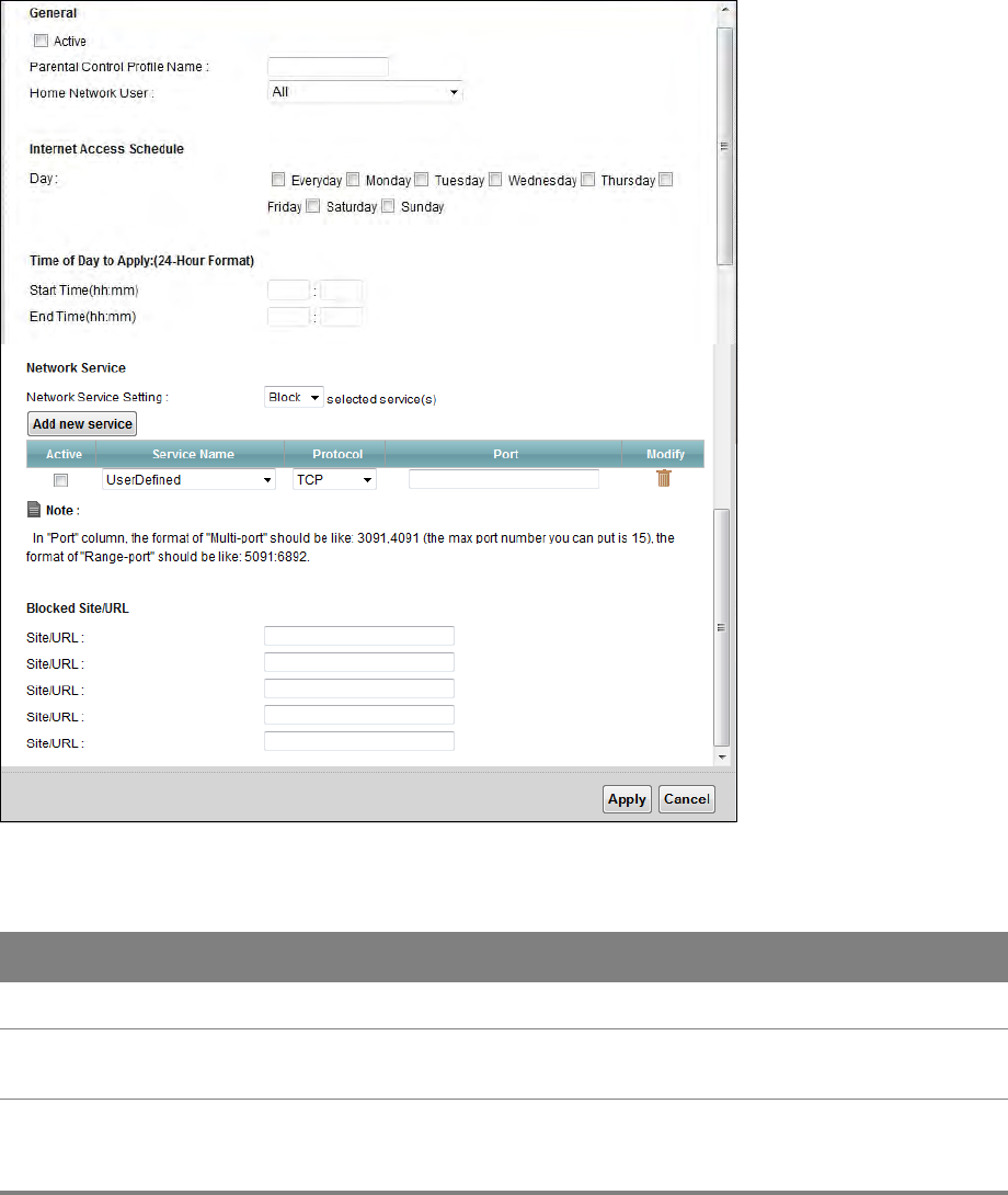
Chapter 12 Parental Control 88
12.1.1 Add/Edit a Parental Control Rule
Click Add new PCP in the Parental Control screen to add a new rule or click the Edit icon next to an
existing rule to edit it. Use this screen to configure a restricted access schedule and/or URL filtering
settings to block the users on your network from accessing certain web sites.
Figure 62 Parental Control: Add/Edit
Table 53 Parental Control: Add/Edit
LABEL DESCRIPTION
Active Select the checkbox to activate this parental control rule.
Parental Control
Profile Name
Enter a descriptive name for the rule.
Home Network
User
Select the LAN user that you want to apply this rule to from the drop-down list box.
If you select Custom, enter the LAN user’s MAC address. If you select All, the rule
applies to all LAN users.

Chapter 12 Parental Control 89
Internet Access Schedule
Day Select check boxes for the days that you want the Router to perform parental
control.
Time of Day to Apply: (24-Hour Format)
Start Time
End Time
Enter the time period of each day, in 24-hour format, during which parental control
will be enforced.
Network Service
Setting
If you select Block, the Router prohibits the users from viewing the Web sites with
the URLs listed below.
If you select Access, the Router blocks access to all URLs except ones listed below.
Add new service Click this to show a screen in which you can add a new service rule. You can
configure the Service Name, Protocol, and Name of the new rule.
Active Select the check box next to the service to apply this rule to the service. Clear the
check box to not apply this rule to it.
Service Name Select a service.
Protocol For services that support multiple protocols, select the protocol.
Port Specify the port number from 1 to 65535.
Modify Click the Delete icon to delete an existing rule.
Blocked Site/URL Specify web sites or URLs to which the Router blocks access.
Table 53 Parental Control: Add/Edit (continued)
LABEL DESCRIPTION
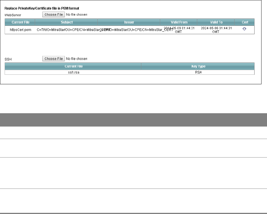
13
Chapter
Chapter 13 Certificates 90
CHAPTER 13
Chapter 13 Certificates
13.1 Local Certificates
Use the Local Certificates screen to view the Router’s summary list of certificates and certification
requests. You can import the following certificates to your Router:
• Web Server - This certificate secures HTTP connections.
• SSH - This certificate secures remote connections.
Click Security > Certificates to open the Local Certificates screen.
Figure 63 Security > Certificates > Local Certificates
Table 54 Security > Certificates > Local Certificates
LABEL DESCRIPTION
WebServer Click Choose File to find the certificate file you want to upload.
Current File This field displays the name used to identify this certificate. It is recommended that
you give each certificate a unique name.
Subject This field displays identifying information about the certificate’s owner, such as CN
(Common Name), OU (Organizational Unit or department), O (Organization or
company) and C (Country). It is recommended that each certificate have unique
subject information.
Issuer This field displays identifying information about the certificate’s issuing certification
authority, such as a common name, organizational unit or department, organization
or company and country.

Chapter 13 Certificates 91
13.2 Trusted CA
Use the Trusted CA screen to view a summary list of certificates of the certification authorities that
you have set the Router to accept as trusted. The Router accepts any valid certificate signed by a
certification authority on this list as being trustworthy; thus you do not need to import any
certificate that is signed by one of these certification authorities.
Valid From This field displays the date that the certificate becomes applicable. The text displays in
red and includes a Not Yet Valid! message if the certificate has not yet become
applicable.
Valid To This field displays the date that the certificate expires. The text displays in red and
includes an Expiring! or Expired! message if the certificate is about to expire or has
already expired.
Cert Click this button and then Save in the File Download screen. The Save As screen
opens, browse to the location that you want to use and click Save.
SSH Type in the location of the SSH certificate file you want to upload in this field or click
Browse to find it.
Choose file Click this link to find the certificate file you want to upload.
Current File This field displays the name used to identify this certificate. It is recommended that
you give each certificate a unique name.
Key Type This field applies to the SSH/SCP/SFTP certificate.
This shows the file format of the current certificate.
Table 54 Security > Certificates > Local Certificates (continued)
LABEL DESCRIPTION
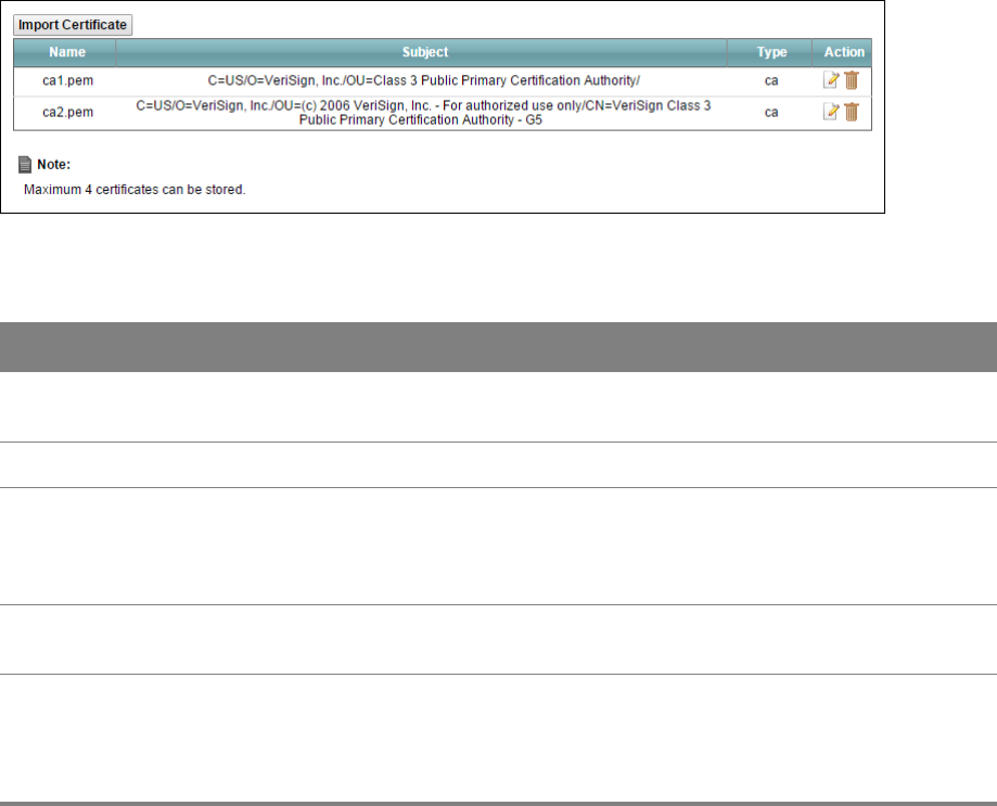
Chapter 13 Certificates 92
Click Security > Certificates > Trusted CA to open the Trusted CA screen.
Figure 64 Security > Certificates > Trusted CA
Table 55 Security > Certificates > Trusted CA
LABEL DESCRIPTION
Import Certificate Click this button to open a screen where you can save the certificate of a certification
authority that you trust to the Router.
Name This field displays the name used to identify this certificate.
Subject This field displays information that identifies the owner of the certificate, such as
Common Name (CN), OU (Organizational Unit or department), Organization (O), State
(ST) and Country (C). It is recommended that each certificate have unique subject
information.
Type This field displays general information about the certificate. ca means that a
Certification Authority signed the certificate.
Action Click the View icon to open a screen with an in-depth list of information about the
certificate (or certification request).
Click the Delete icon to delete the certificate (or certification request). You cannot
delete a certificate that one or more features is configured to use.
13.3 Trusted CA Import
Click Import Certificate in the Trusted CA screen to open the Import Certificate screen. You can
save a trusted certification authority’s certificate to the Router.
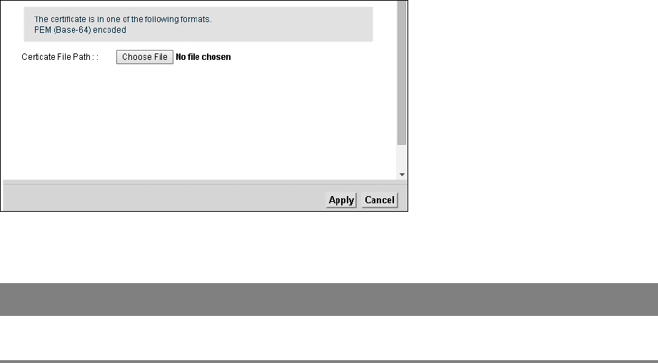
Chapter 13 Certificates 93
You must remove any spaces from the certificate’s filename before you can import the
certificate.
Figure 65 Certificates > Trusted CA: Import
Table 56 Certificates > Trusted CA: Import
LABEL DESCRIPTION
Certificate File
Path
Click Choose File to look for the file you want to upload.
13.4 View Certificate
Use this screen to view in-depth information about the certification authority’s certificate, change
the certificate’s name.
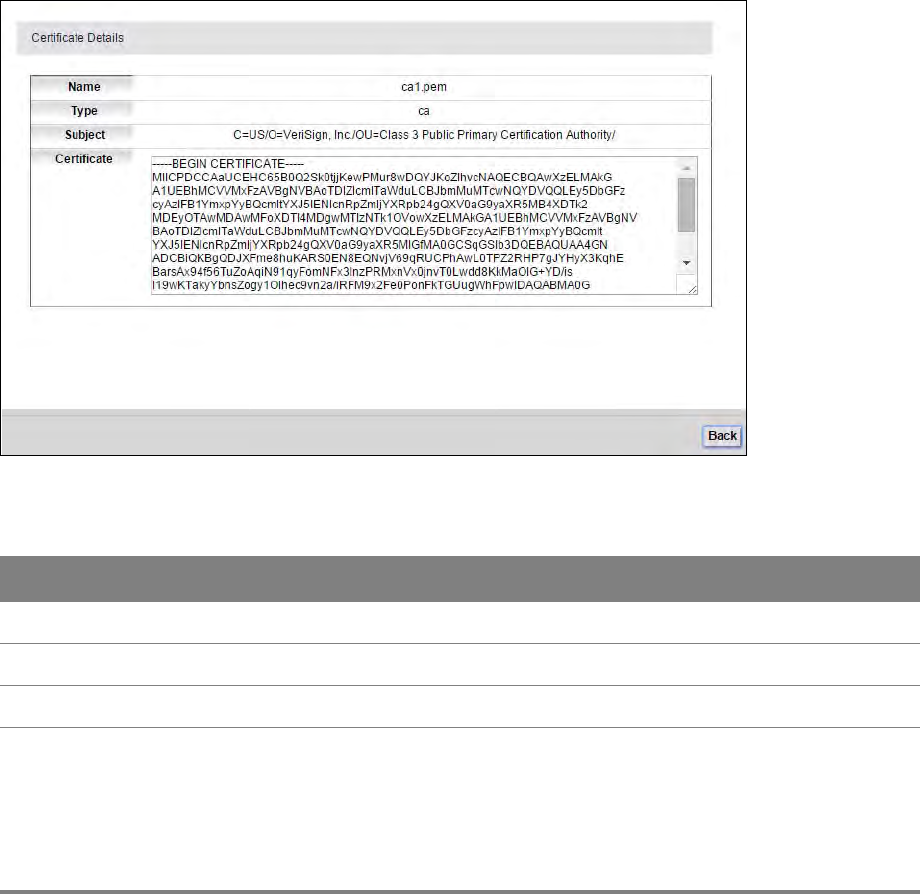
Chapter 13 Certificates 94
Click Security > Certificates > Trusted CA to open the Trusted CA screen. Click the View icon to
open the View Certificate screen.
Figure 66 Security > Certificates > Trusted CA > View
Table 57 Security > Certificates > Trusted CA > View
LABEL DESCRIPTION
Name This field displays the identifying name of this certificate.
Type This field displays the type of this certificate.
Subject This field displays the subject of this certificate.
Certificate This read-only text box displays the certificate or certification request in Privacy
Enhanced Mail (PEM) format. PEM uses 64 ASCII characters to convert the binary
certificate into a printable form.
You can copy and paste the certificate into an e-mail to send to friends or
colleagues or you can copy and paste the certificate into a text editor and save the
file on a management computer for later distribution (via floppy disk for example).
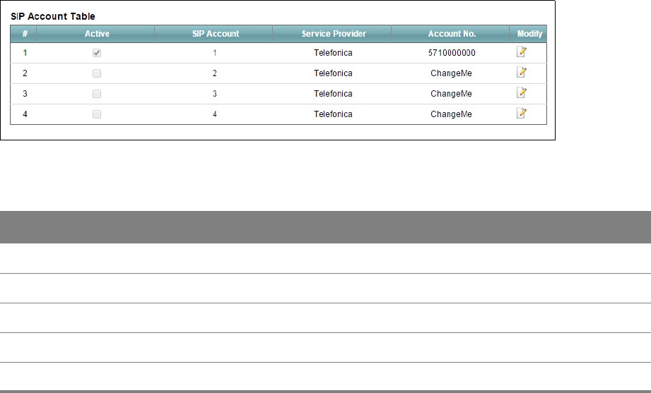
14
Chapter
Chapter 14 VoIP 95
CHAPTER 14
Chapter 14 VoIP
14.1 The SIP Account Screen
The Router uses a SIP (Session Initiation Protocol) account to make outgoing VoIP calls and check if
an incoming call’s destination number matches your SIP account’s SIP number. In order to make or
receive a VoIP call, you need to enable and configure a SIP account, and map it to a phone port. The
SIP account contains information that allows your Router to connect to your VoIP service provider.
To access the following screen, click VoIP > SIP > SIP Account.
Figure 67 VoIP > SIP > SIP Account
Table 58 VoIP > SIP > SIP Account
LABEL DESCRIPTION
Active This shows whether the SIP account is activated or not.
SIP Account This shows the name of the SIP account.
Service Provider This shows the name of the SIP service provider.
Account No. This shows the SIP number.
Modify Click the Edit icon to configure the SIP account.
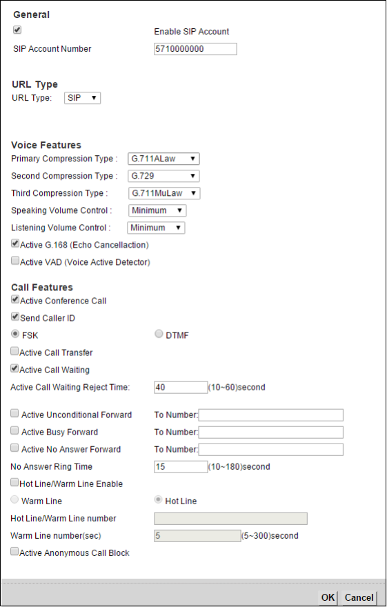
Chapter 14 VoIP 96
14.1.1 Edit SIP Account
You can configure a SIP account. To access this screen, click the Edit icon next to an account.
Figure 68 SIP > SIP Account: Add/Edit

Chapter 14 VoIP 97
Table 59 SIP > SIP Account: Edit
LABEL DESCRIPTION
Enable SIP
Account
Select the check box to use this account. Clear it to not use this account.
SIP Account
Number
Enter your SIP number. In the full SIP URI, this is the part before the @ symbol.
Username Enter the user name for registering this SIP account, exactly as it was given to you.
Password Enter the password for registering this SIP account, exactly as it was given to you.
URL Type Select whether or not to include the SIP service domain name when the Router sends
the SIP number.
SIP - include the SIP service domain name.
TEL - do not include the SIP service domain name.
Primary /
Secondary / Third
Compression Type
Select the type of voice coder/decoder (codec) that you want the Router to use. G.711
provides higher voice quality but requires more bandwidth (64 kbps).
When two SIP devices start a SIP session, they must agree on a codec.
Select the Router’s first, second, and third choice for voice coder/decoder.
Select None for the second and third choice if you only want the Router to accept the
first choice.
Speaking
Volume
Control
Select the loudness that the Router uses for speech that it sends to the peer device.
Listening
Volume
Control
Select the loudness that the Router uses for speech that it receives from the peer
device.
Active G.168 (Echo
Cancellation)
Select this if you want to eliminate the echo caused by the sound of your voice
reverberating in the telephone receiver while you talk.
Active VAD (Voice
Active Detector)
Select this if the Router should stop transmitting when you are not speaking. This
reduces the bandwidth the Router uses.
Send Caller ID Select this if you want to send identification when you make VoIP phone calls. Clear
this if you do not want to send identification.
Active Call
Transfer
Select this to enable call transfer on the Router. This allows you to transfer an
incoming call (that you have answered) to another phone.
Active Call Waiting Select this to enable call waiting on the Router. This allows you to place a call on hold
while you answer another incoming call on the same telephone (directory) number.
Active Call Waiting
Reject Time
Specify a time of seconds that the Router waits before rejecting the second call if you
do not answer it.
Active
Unconditional
Forward
Select this if you want the Router to forward all incoming calls to the specified phone
number.
Specify the phone number in the To Number field on the right.

Chapter 14 VoIP 98
Active Busy
Forward
Select this if you want the Router to forward incoming calls to the specified phone
number if the phone port is busy.
Specify the phone number in the To Number field on the right.
If you have call waiting, the incoming call is forwarded to the specified phone number
if you reject or ignore the second incoming call.
Active No Answer
Forward
Select this if you want the Router to forward incoming calls to the specified phone
number if the call is unanswered. (See No Answer Time.)
Specify the phone number in the To Number field on the right.
No Answer Ring
Time
This field is used by the Active No Answer Forward feature.
Enter the number of seconds the Router should wait for you to answer an incoming
call before it considers the call is unanswered.
Hot Line / Warm
Line Enable
Select this to enable the hot line or warm line feature on the Router.
Warm Line Select this to have the Router dial the specified warm line number after you pick up
the telephone and do not press any keys on the keypad for a period of time.
Hot Line Select this to have the Router dial the specified hot line number immediately when
you pick up the telephone.
Hot Line / Warm
Line number
Enter the number of the hot line or warm line that you want the Router to dial.
Warm Line
number (sec)
Enter a number of seconds that the Router waits before dialing the warm line number
if you pick up the telephone and do not press any keys on the keypad.
Active Anonymous
Call Block
Select this to have the phone not ring for incoming calls with caller ID deactivated.
Table 59 SIP > SIP Account: Edit (continued)
LABEL DESCRIPTION
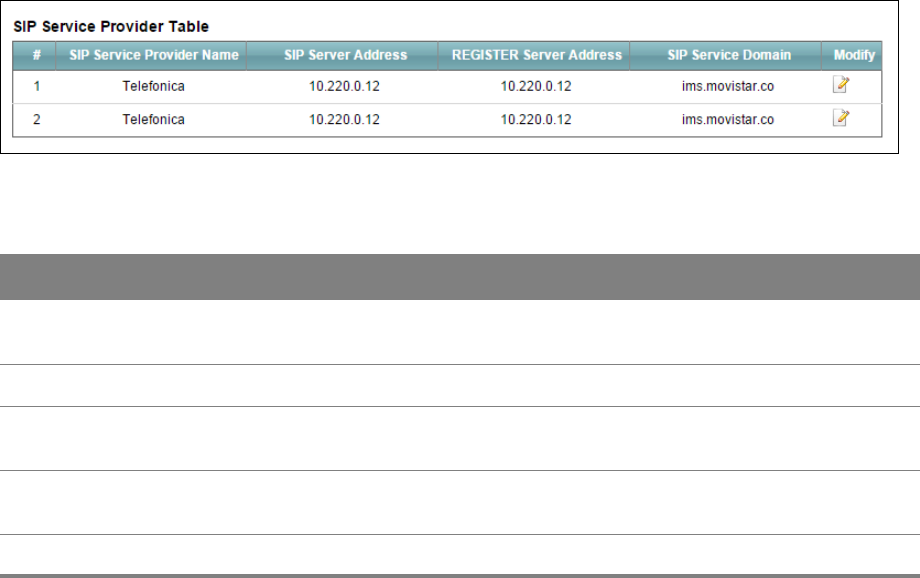
Chapter 14 VoIP 99
14.2 The SIP Service Provider Screen
Use this screen to manage profiles of SIP service provider settings. Click VoIP > SIP > SIP Service
Provider to open the SIP Service Provider screen.
Figure 69 VoIP > SIP > SIP Service Provider
Table 60 VoIP > SIP > SIP Service Provider
LABEL DESCRIPTION
SIP Service
Provider Name
This shows the name of the SIP service provider.
SIP Server Address This shows the IP address or domain name of the SIP server.
REGISTER Server
Address
This shows the IP address or domain name of the SIP register server.
SIP Service
Domain
Enter the SIP service domain name. In the full SIP URI, this is the part after the @
symbol. You can use up to 127 printable ASCII Extended set characters.
Modify Click the Edit icon to configure the profile of SIP service provider settings.
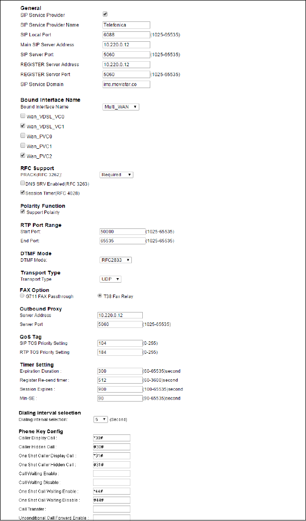
Chapter 14 VoIP 100
14.2.1 Edit SIP Service Provider
Use this screen to configure the SIP server information, QoS for VoIP calls, the numbers for certain
phone functions and dialing plan for a SIP service provider. Click VoIP > SIP > SIP Service Provider
and then click the Edit icon next to a profile of SIP service provider settings to open the following
screen.
Figure 70 VoIP > SIP > SIP Service Provider > Edit
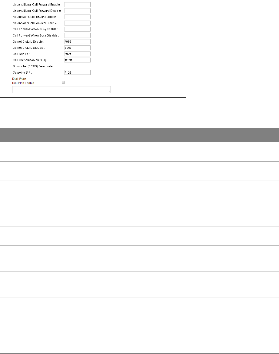
Chapter 14 VoIP 101
Figure 71 SIP > SIP Service Provider > Edit (continued)
Table 61 SIP > SIP Service Provider: Edit
LABEL DESCRIPTION
SIP Service
Provider
Select this if you want the Router to use this SIP provider. Clear it if you do not want
the Router to use this SIP provider.
SIP Service
Provider Name
Enter the name of your SIP service provider.
SIP Local Port Enter the Router’s listening port number, if your VoIP service provider gave you one.
Otherwise, keep the default value.
Main SIP Server
Address
Enter the IP address or domain name of the SIP server provided by your VoIP service
provider. You can use up to 95 printable ASCII characters. It does not matter whether
the SIP server is a proxy, redirect or register server.
SIP Server Port Enter the SIP server’s listening port number, if your VoIP service provider gave you
one. Otherwise, keep the default value.
REGISTER Server
Address
Enter the IP address or domain name of the SIP register server, if your VoIP service
provider gave you one. Otherwise, enter the same address you entered in the SIP
Server Address field. You can use up to 95 printable ASCII characters.
REGISTER Server
Port
Enter the SIP register server’s listening port number, if your VoIP service provider gave
you one. Otherwise, enter the same port number you entered in the SIP Server Port
field.
SIP Service
Domain
Enter the SIP service domain name. In the full SIP URI, this is the part after the @
symbol. You can use up to 127 printable ASCII Extended set characters.
Bound Interface
Name
If you select Any_WAN, the Router automatically activates the VoIP service when any
WAN connection is up.
If you select Multi_WAN, you also need to select the pre-configured WAN connections.
The VoIP service is activated only when one of the selected WAN connections is up.

Chapter 14 VoIP 102
PRACK (RFC 3262) RFC 3262 defines a mechanism to provide reliable transmission of SIP provisional
response messages, which convey information on the processing progress of the
request. This uses the option tag 100rel and the Provisional Response
ACKnowledgement (PRACK) method.
Select Supported or Required to have the Router include a SIP Require/Supported
header field with the option tag 100rel in all INVITE requests. When the Router
receives a SIP response message indicating that the phone it called is ringing, the
Router sends a PRACK message to have both sides confirm the message is received.
If you select Supported, the peer device supports the option tag 100rel to send
provisional responses reliably.
If you select Required, the peer device requires the option tag 100rel to send
provisional responses reliably.
Select Disabled to turn off this function.
DNS SRV Enabled
(RFC 3263)
Select this to have the Router query your ISP’s DNS server for a list of any available SIP
servers that it maintains. This is useful if your static SIP server experiences difficulties,
making it hard for your IP phone users to make SIP calls.
Session Timer
(RFC 4028)
Select this to have the Router support RFC 4028.
This makes sure that SIP sessions do not hang and the SIP line can always be available
for use.
RTP Port Range Enter the listening port number(s) for RTP traffic provided by your VoIP service
provider.
Start Port
End Port
If your VoIP service provider gave you this information. Otherwise, keep the default
values.
To enter one port number, enter the port number in the Start Port and End Port
fields.
To enter a range of ports,
• enter the port number at the beginning of the range in the Start Port field.
• enter the port number at the end of the range in the End Port field.
DTMF Mode Control how the Router handles the tones that your telephone makes when you push
its buttons. You should use the same mode your VoIP service provider uses.
RFC2833 - send the DTMF tones in RTP packets.
Inband - send the DTMF tones in the voice data stream. This method works best when
you are using a codec that does not use compression (like G.711). Codecs that use
compression (like G.726) can distort the tones.
SIPInfo - send the DTMF tones in SIP messages.
Transport Type The transport layer protocol used for SIP is UDP.
FAX Option This field controls how the Router handles fax messages.
G711 Fax
Passthrough
Select this if the Router should use G.711 to send fax messages. The peer devices
must also use G.711.
Table 61 SIP > SIP Service Provider: Edit (continued)
LABEL DESCRIPTION

Chapter 14 VoIP 103
T38 Fax Relay Select this if the Router should send fax messages as UDP or TCP/IP packets through
IP networks. This provides better quality, but it may have inter-operability problems.
The peer devices must also use T.38.
Server Address Enter the IP address or domain name of the SIP outbound proxy server.
Server Port Enter the SIP outbound proxy server’s listening port, if your VoIP service provider gave
you one. Otherwise, keep the default value.
SIP TOS Priority
Setting
Enter the DSCP (DiffServ Code Point) number for SIP message transmissions. The
Router creates Class of Service (CoS) priority tags with this number to SIP traffic that it
transmits.
RTP TOS Priority
Setting
Enter the DSCP (DiffServ Code Point) number for RTP voice transmissions. The Router
creates Class of Service (CoS) priority tags with this number to RTP traffic that it
transmits.
Expiration
Duration
Enter the number of seconds your SIP account is registered with the SIP register
server before it is deleted. The Router automatically tries to re-register your SIP
account when one-half of this time has passed. (The SIP register server might have a
different expiration.)
Register Re-send
timer
Enter the number of seconds the Router waits before it tries again to register the SIP
account, if the first try failed or if there is no response.
Session Expires Enter the number of seconds the Router lets a SIP session remain idle (without traffic)
before it automatically disconnects the session.
Min-SE Enter the minimum number of seconds the Router lets a SIP session remain idle
(without traffic) before it automatically disconnects the session. When two SIP devices
start a SIP session, they must agree on an expiration time for idle sessions. This field is
the shortest expiration time that the Router accepts.
Dialing interval
selection
Enter the number of seconds the Router should wait after you stop dialing numbers
before it makes the phone call. The value depends on how quickly you dial phone
numbers.
Phone Key Config
Use this section to customize the phone keypad combinations you use to access certain features on the
Router.
Caller Display Call This code is used to display the caller ID for outgoing calls.
Caller Hidden Call This code is used to hide the caller ID for outgoing calls.
One Shot Caller
Display Call
This code is used to display the caller ID only for the phone call your are going to
make.
One Shot Caller
Hidden Call
This code is used to hide the caller ID only for the phone call your are going to make.
Table 61 SIP > SIP Service Provider: Edit (continued)
LABEL DESCRIPTION

Chapter 14 VoIP 104
Call Waiting
Enable
This code is used to turn the call waiting feature on. With call waiting, you hear a
special beep notifying you of another incoming call while you have a call. It allows you
to place the first incoming call on hold and answer the second call so that you won’t
miss any important calls.
Call Waiting
Disable
This code is used to turn the call waiting feature off.
One Shot Call
Waiting Enable
This code is used to enable call waiting only for the phone call your are going to make.
See the description for the Call Waiting Enable field for more information.
One Shot Call
Waiting Disable
This code is used to disable one shot call waiting.
Call Transfer This code is used to enable call transfer that allows you to transfer an incoming call
(that you have answered) to another phone.
Unconditional Call
Forward Enable
This code is used to enable unconditional call forwarding. Incoming calls are always
forwarded to a specified number without any condition.
Unconditional Call
Forward Disable
This code is used to disable unconditional call forwarding.
No Answer Call
Forward Enable
This code is used to enable call forwarding when there is no answer at a SIP number
(no one picked up the connected phone that uses the SIP number).
No Answer Call
Forward Disable
This code is used to disable call forwarding when there is no answer at a SIP number
(no one picked up the connected phone that uses the SIP number).
Call Forward
When Busy Enable
This code is used to enable call forwarding when the phone is busy.
Call Forward
When Busy
Disable
This code is used to disable call forwarding when the phone is busy.
Do Not Disturb
Enable
This code is used to turn the do not disturb feature on. This has the Router reject all
calls destined to the phone line.
Do Not Disturb
Disable
This code is used to turn the Do Not Disturb feature off.
Call Return Specify the key combinations that you can enter to place a call to the last number that
called you.
Call Completion
on Busy
Subscriber (CCBS)
Deactivate
Call Completion on Busy Subscriber (CCBS) lets a subscriber have the VoIP server alert
him when a called subscriber becomes available if the subscriber’s line was busy
when the call was attempted.
Enter the key combinations that you can enter to disable CCBS.
Table 61 SIP > SIP Service Provider: Edit (continued)
LABEL DESCRIPTION
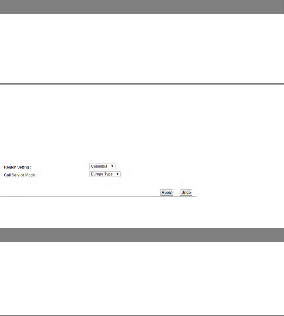
Chapter 14 VoIP 105
14.3 Phone Screen
Use this screen to maintain settings that depend on which region of the world the Router is in. To
access this screen, click VoIP > Phone.
Figure 72 VoIP > Phone
Table 62 VoIP > Phone
LABEL DESCRIPTION
Region Setting Select the place in which the Router is located.
Call Service Mode Select the mode for supplementary phone services (call hold, call waiting, call
transfer and three-way conference calls) that your VoIP service provider
supports.
•Europe Type - use supplementary phone services in European mode.
•USA Type - use supplementary phone services American mode.
You might have to subscribe to these services to use them. Contact your VoIP
service provider.
Outgoing SIP Enter the key combinations that you can enter to select the SIP account that you use
to make outgoing calls.
If you enter #12 (by default) <SIP account index number>#<the phone number you
want to call>, #1201#12345678 for example, the Router uses the first SIP account to
call 12345678.
Dial Plan
Dial Plan Enable Select this to activate the dial plan rules you specify in the text box provided.
Table 61 SIP > SIP Service Provider: Edit (continued)
LABEL DESCRIPTION
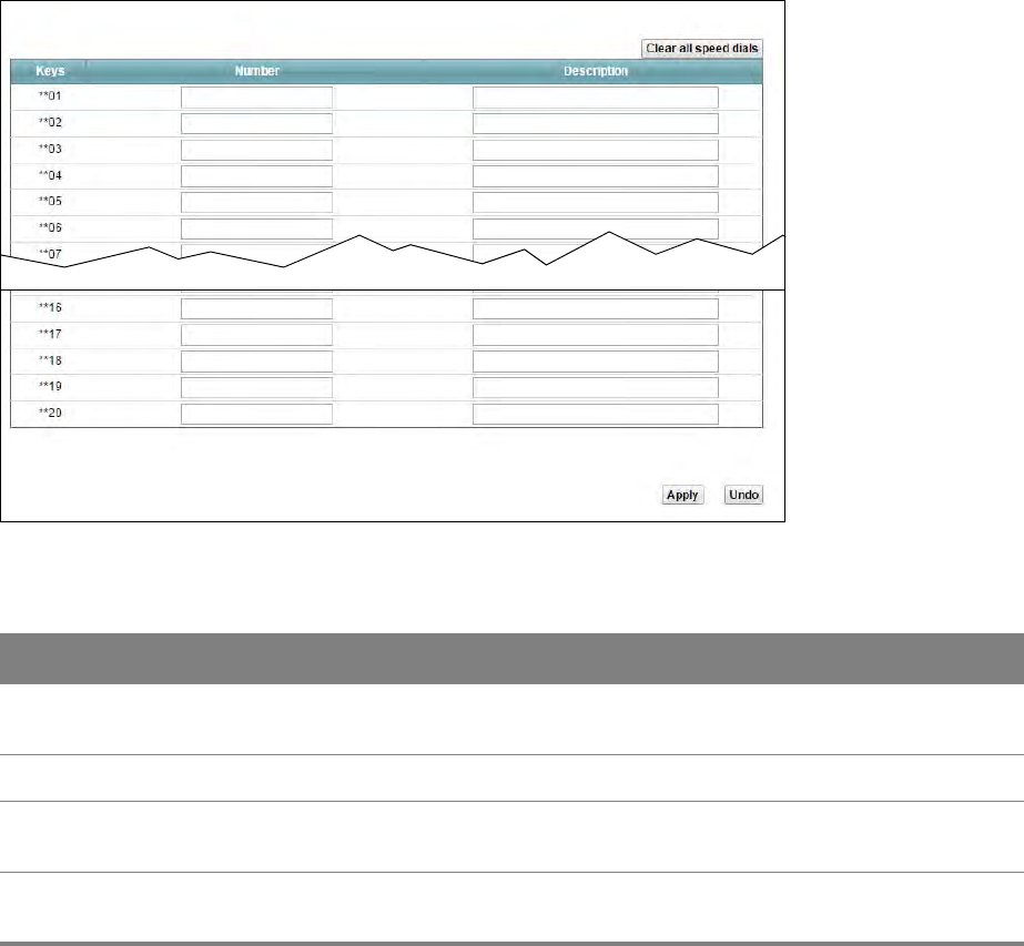
Chapter 14 VoIP 106
14.4 Call Rule Screen
Use this screen to add, edit, or remove speed-dial numbers for outgoing calls. Speed dial provides
shortcuts for dialing frequently-used (VoIP) phone numbers. You also have to create speed-dial
entries if you want to call SIP numbers that contain letters. Once you have configured a speed dial
rule, you can use a shortcut (the speed dial number, #01 for example) on your phone's keypad to
call the phone number.
To access this screen, click VoIP > Call Rule.
Figure 73 VoIP > Call Rule
Table 63 VoIP > Call Rule
LABEL DESCRIPTION
Clear all speed
dials
Click this to erase all the speed-dial entries.
Keys This field displays the speed-dial number you should dial to use this entry.
Number Enter the SIP number you want the Router to call when you dial the speed-dial
number.
Description Enter a short description to identify the party you call when you dial the speed-dial
number. You can use up to 127 printable ASCII characters.
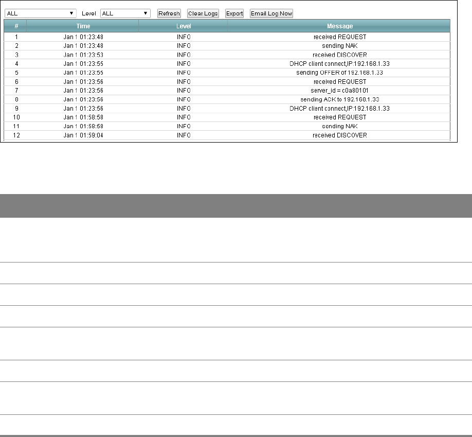
15
Chapter
Chapter 15 System Monitor 107
CHAPTER 15
Chapter 15 System Monitor
15.1 The Log Screen
Click System Monitor > Log to open the Log screen. Use the Log screen to see the system logs for
the categories that you select in the upper left drop-down list box.
Figure 74 System Monitor > Log
Table 64 System Monitor > Log
LABEL DESCRIPTION
Level Select a severity level from the drop-down list box. This filters search results according
to the severity level you have selected. When you select a severity, the Router searches
through all logs of that severity or higher.
Refresh Click this to renew the log screen.
Clear Logs Click this to delete all the logs.
Export Click this to save a copy of the logs to your computer.
Email Log Now Click this to have the Router send the log to the email server you configured in the Log
Setting screen.
Time This field displays the time the log was recorded.
Level This field displays the severity level of the logs that the device is to send to this syslog
server.
Messages This field states the reason for the log.
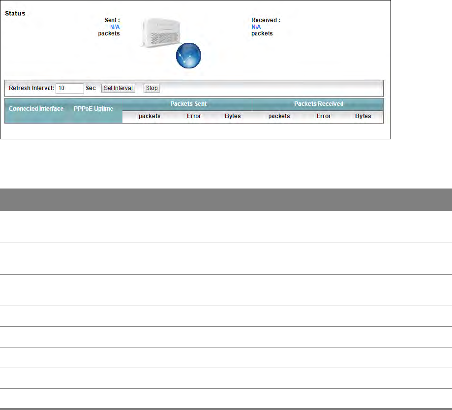
Chapter 15 System Monitor 108
15.2 The WAN Traffic Status Screen
Click System Monitor > Traffic Status to open the WAN Traffic Status screen. You can view the
WAN traffic statistics in this screen.
Figure 75 System Monitor > Traffic Status > WAN
Table 65 System Monitor > Traffic Status > WAN
LABEL DESCRIPTION
Status This shows the number of bytes sent and received through the WAN interface of the
Router.
Refresh Interval Specify how often you want the Router to update this screen and click Set Interval to
apply the change. Click Stop to halt updating of the screen.
Connected
Interface
This shows the name of the WAN interface that is currently connected.
PPPoE Uptime This shows the time duration of the PPPoE connection.
Packets Sent /Received
packets This indicates the number of transmitted/received packets on this interface.
Error This indicates the number of frames with errors transmitted/received on this interface.
Bytes This indicates the number of bytes transmitted/received through the interface.
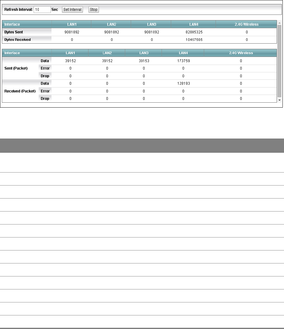
Chapter 15 System Monitor 109
15.3 The LAN Traffic Status Screen
Click System Monitor > Traffic Status > LAN to open the following screen. You can view the LAN
traffic statistics in this screen.
Figure 76 System Monitor > Traffic Status > LAN
Table 66 System Monitor > Traffic Status > LAN
LABEL DESCRIPTION
Refresh Interval Specify how often you want the Router to update this screen and click Set Interval to
apply the change. Click Stop to halt updating of the screen.
Interface This shows the LAN or WLAN interface.
Bytes Sent This indicates the number of bytes transmitted on this interface.
Bytes Received This indicates the number of bytes received on this interface.
Interface This shows the LAN or WLAN interface.
Sent (Packet)
Data This indicates the number of transmitted packets on this interface.
Error This indicates the number of frames with errors transmitted on this interface.
Drop This indicates the number of outgoing packets dropped on this interface.
Received (Packet)
Data This indicates the number of received packets on this interface.
Error This indicates the number of frames with errors received on this interface.
Drop This indicates the number of received packets dropped on this interface.
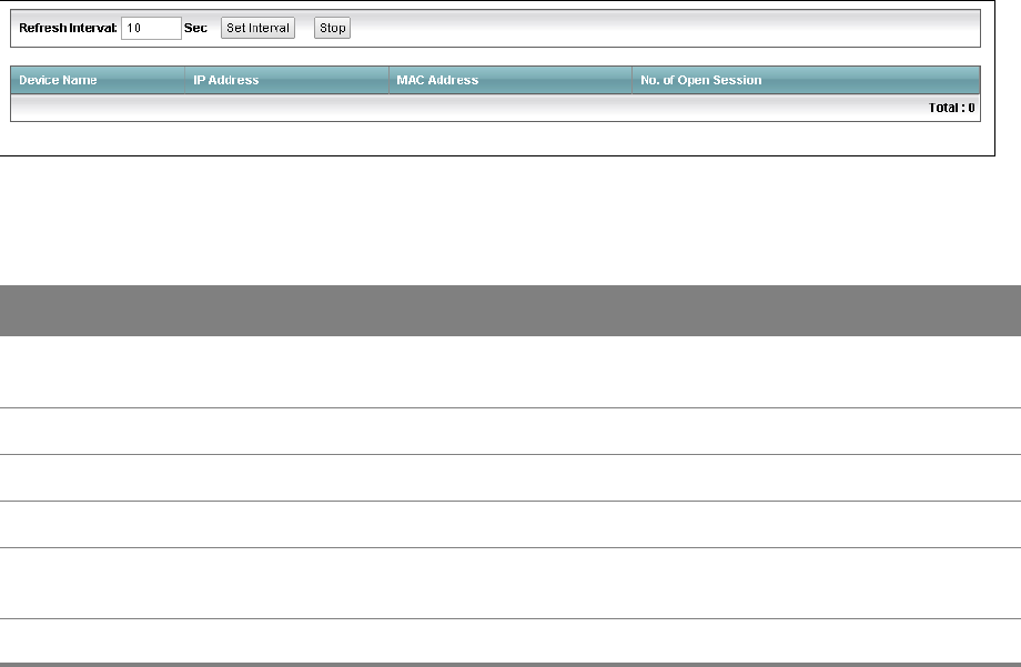
Chapter 15 System Monitor 110
15.4 The NAT Traffic Status Screen
Click System Monitor > Traffic Status > NAT to open the following screen. You can view the NAT
status of the Router’s clients in this screen.
Figure 77 System Monitor > Traffic Status > NAT
Table 67 System Monitor > Traffic Status > NAT
LABEL DESCRIPTION
Refresh Interval Specify how often you want the Router to update this screen and click Set Interval to
apply the change. Click Stop to halt updating of the screen.
Device Name This shows the name of the client.
IP Address This shows the IP address of the client.
MAC Address This shows the MAC address of the client.
No. of Open
Session
This shows the number of NAT sessions used by the client.
Total This shows the total number of NAT sessions currently open on the Router.
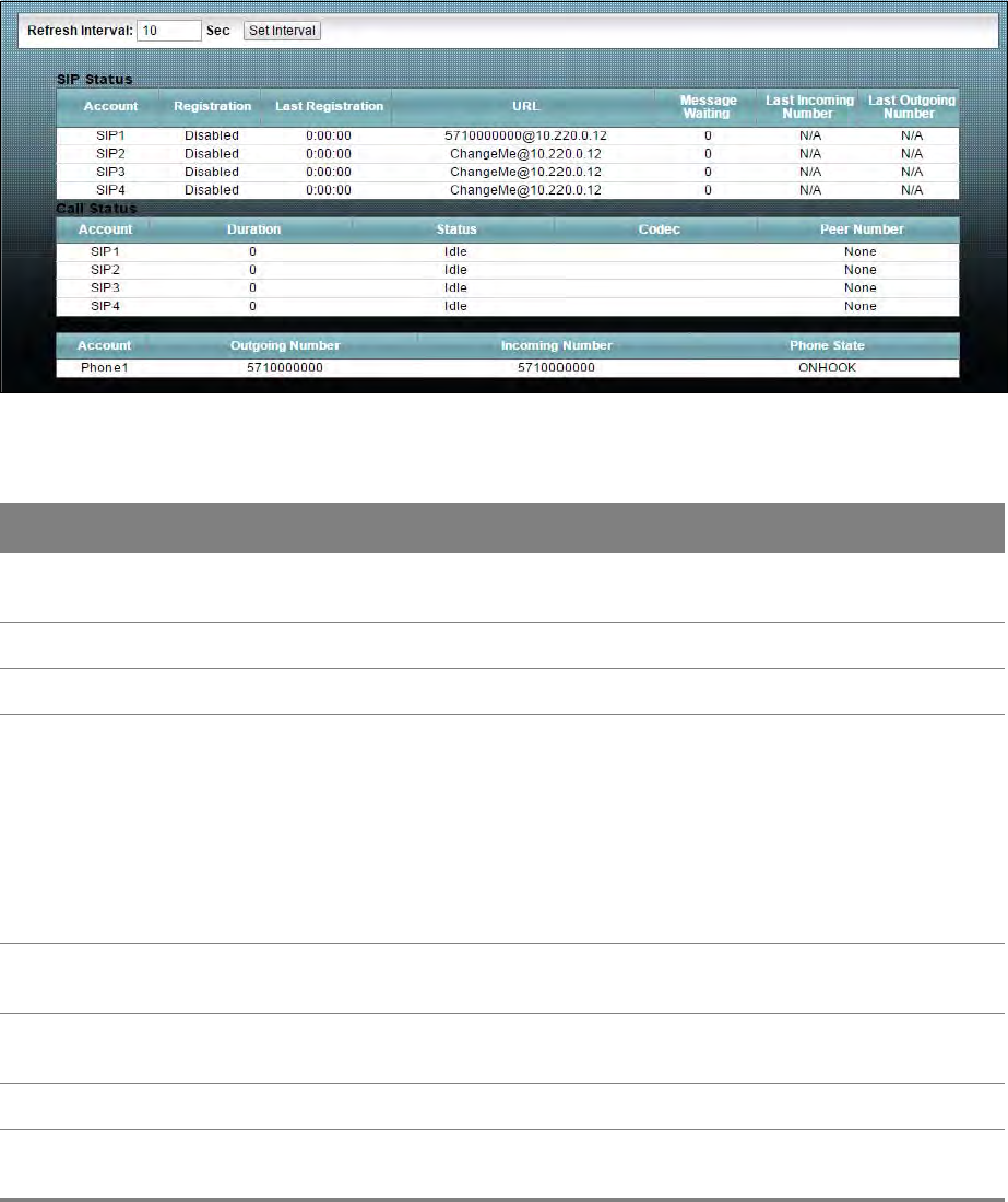
Chapter 15 System Monitor 111
15.5 The VoIP Status Screen
Click System Monitor > VoIP Status to open the following screen. You can view the VoIP traffic
statistics in this screen.
Figure 78 System Monitor > VoIP Status
Table 68 System Monitor > VoIP Status
LABEL DESCRIPTION
Refresh Interval Specify how often you want the Router to update this screen and click Set Interval to
apply the change.
SIP Status
Account This column displays each SIP account in the Router.
Registration This field displays the current registration status of the SIP account. You can change this
in the Status screen.
Registered - The SIP account is registered with a SIP server.
Not Registered - The last time the Router tried to register the SIP account with the SIP
server, the attempt failed. The Router automatically tries to register the SIP account
when you turn on the Router or when you activate it.
Inactive - The SIP account is not active. You can activate it in VoIP > SIP > SIP Account.
Last Registration This field displays the last time you successfully registered the SIP account. The field is
blank if you never successfully registered this account.
URL This field displays the account number and service domain of the SIP account. You can
change these in the VoIP > SIP screens.
Message Waiting This field indicates whether or not there are any messages waiting for the SIP account.
Last Incoming
Number
This field displays the last number that called the SIP account. The field is blank if no
number has ever dialed the SIP account.

Chapter 15 System Monitor 112
Last Outgoing
Number
This field displays the last number the SIP account called. The field is blank if the SIP
account has never dialed a number.
Call Status
Account This column displays each SIP account in the Router.
Duration This field displays how long the current call has lasted.
Status This field displays the current state of the phone call.
Idle - There are no current VoIP calls, incoming calls or outgoing calls being made.
Dial - The callee’s phone is ringing.
Ring - The phone is ringing for an incoming VoIP call.
Process - There is a VoIP call in progress.
DISC - The callee’s line is busy, the callee hung up or your phone was left off the hook.
Codec This field displays what voice codec is being used for a current VoIP call through a
phone port.
Peer Number This field displays the SIP number of the party that is currently engaged in a VoIP call
through a phone port.
Phone Status
Account This field displays the phone accounts of the Router.
Outgoing
Number
This field displays the SIP number that you use to make calls on this phone port.
Incoming
Number
This field displays the SIP number that you use to receive calls on this phone port.
Phone State This field shows whether or the phone connected to the subscriber port is on-hook
ONHOOK) or off-hook (OFFHOOK).
Table 68 System Monitor > VoIP Status (continued)
LABEL DESCRIPTION
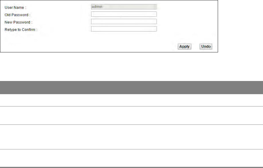
16
Chapter
Chapter 16 User Account 113
CHAPTER 16
Chapter 16 User Account
16.1 Overview
You can configure the system password in the User Account screen.
16.2 The User Account Screen
Use the User Account screen to configure system password.
Click Maintenance > User Account to open the following screen.
Figure 79 Maintenance > User Account
Table 69 Maintenance > User Account
LABEL DESCRIPTION
User Name This is the name of the user account.
Old Password Type the default password or the existing password you use to access the system in this
field.
New Password Type your new system password (4-64 characters). Note that as you type a password,
the screen displays a (*) for each character you type. After you change the password,
use the new password to access the Router.
Retype to
Confirm
Type the new password again for confirmation.
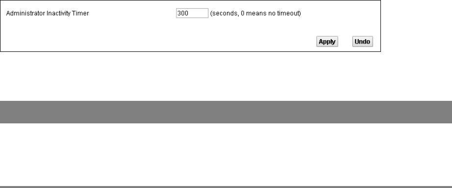
17
Chapter
Chapter 17 System 114
CHAPTER 17
Chapter 17 System
17.1 The System Screen
Use the System screen to configure the system’s inactivity time-out interval.
Click Maintenance > System to open the following screen.
Figure 80 Maintenance > System
Table 70 Maintenance > System
LABEL DESCRIPTION
Administrator
Inactivity Timer
Type how many seconds a management session (either via the web configurator) can be
left idle before the session times out. After it times out you have to log in with your
password again. Very long idle timeouts may have security risks. A value of "0" means a
management session never times out, no matter how long it has been left idle (not
recommended).
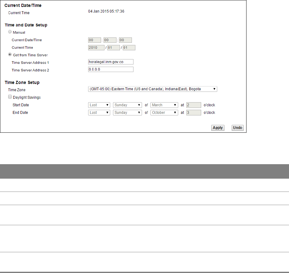
18
Chapter
Chapter 18 Time Setting 115
CHAPTER 18
Chapter 18 Time Setting
18.1 The Time Setting Screen
To change your Router’s time and date, click Maintenance > Time. The screen appears as shown.
Use this screen to configure the Router’s time based on your local time zone.
Figure 81 Maintenance > Time Setting
Table 71 Maintenance > System > Time Setting
LABEL DESCRIPTION
Current Time This field displays the date and time of your Router.
Manual Select this to enter the time and date manually in hh:mm:ss and yyyy/mm/dd format.
Get from Time
Server
Select this to have the Router get the time automatically from a time server.
Time Server
Address 1, 2
Enter the IP address or URL (up to 31 extended ASCII characters in length) of your
time server. Check with your ISP/network administrator if you are unsure of this
information.
Time Zone Choose the time zone of your location. This will set the time difference between your
time zone and Greenwich Mean Time (GMT).

Chapter 18 Time Setting 116
Daylight Savings Daylight saving is a period from late spring to early fall when many countries set their
clocks ahead of normal local time by one hour to give more daytime light in the
evening. Select this option if you use Daylight Saving Time.
Start/End Date Configure the day and time when Daylight Saving Time starts/ends if you selected
Daylight Savings. The o'clock field uses the 24 hour format.
Table 71 Maintenance > System > Time Setting (continued)
LABEL DESCRIPTION
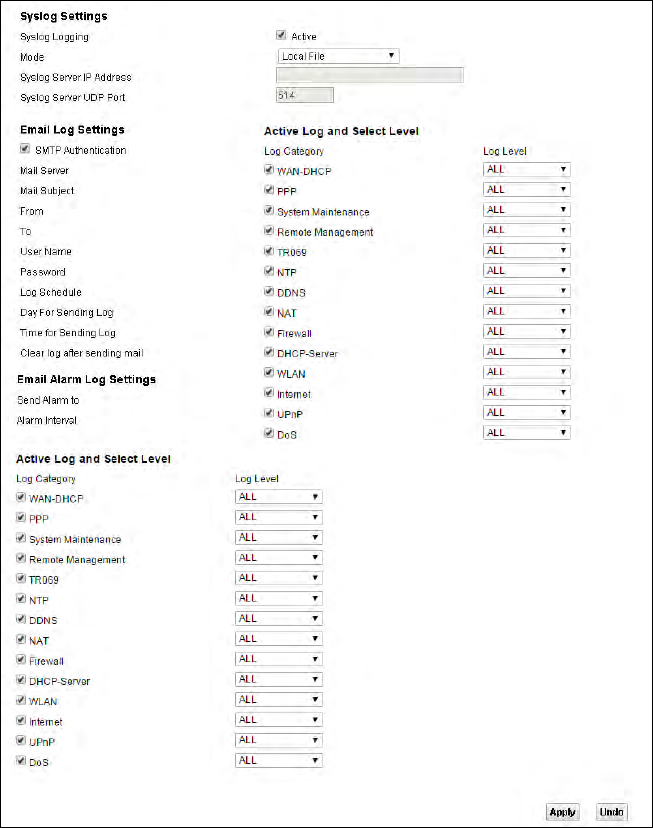
19
Chapter
Chapter 19 Log Setting 117
CHAPTER 19
Chapter 19 Log Setting
19.1 The Log Setting Screen
To change your Router’s log settings, click Maintenance > Log Setting. The screen appears as
shown.
Figure 82 Maintenance > Log Setting

Chapter 19 Log Setting 118
Table 72 Maintenance > Log Setting
LABEL DESCRIPTION
Syslog Logging Select the Active check box to enable syslog logging.
Mode Select Local File to have the Router save the log file locally.
Select Local File and Remote to have the Router save the log file locally and send it to
an external syslog server.
Syslog Server IP
Address
If you select Local File and Remote in the Mode field, enter the server name or IP
address of the syslog server that will log the selected categories of logs.
Syslog Server
UDP Port
If you select Local File and Remote in the Mode field, enter the port number used by
the syslog server.
SMTP
Authentication
SMTP (Simple Mail Transfer Protocol) is the message-exchange standard for the
Internet. SMTP enables you to move messages from one E-mail server to another.
Select the check box to activate SMTP authentication. If mail server authentication is
needed but this feature is disabled, you will not receive the E-mail logs.
Mail Server Enter the server name or the IP address of the mail server for the e-mail addresses
specified below. If this field is left blank, logs and alert messages will not be sent via E-
mail.
Mail Subject Type a title that you want to be in the subject line of the system log e-mail message that
the Router sends.
From Specify where the logs are sent from.
To The Router sends logs to the e-mail address specified in this field. If this field is left
blank, the Router does not send logs via E-mail.
User Name Enter the user name (up to 32 characters) (usually the user name of a mail account).
Password Enter the password associated with the user name above.
Log Schedule Specify the schedule for sending log. Specify days and times for sending logs in the
following fields.
Day For Sending
Log
Specify the day for sending log.
Time for
Sending Log
Specify the time for sending log.
Clear log after
sending mail
Select this to delete all the logs after the Router sends an E-mail of the logs.
Send Alarm to Enter the E-mail address where the alarm messages will be sent.
Alarm Interval Specify the number of seconds between the sending of alarm log e-mails.

Chapter 19 Log Setting 119
Log Category Select the categories of logs that you want to record.
Log Level Select the severity level of logs that you want to record. If you want to record all logs,
select ALL.
Table 72 Maintenance > Log Setting (continued)
LABEL DESCRIPTION
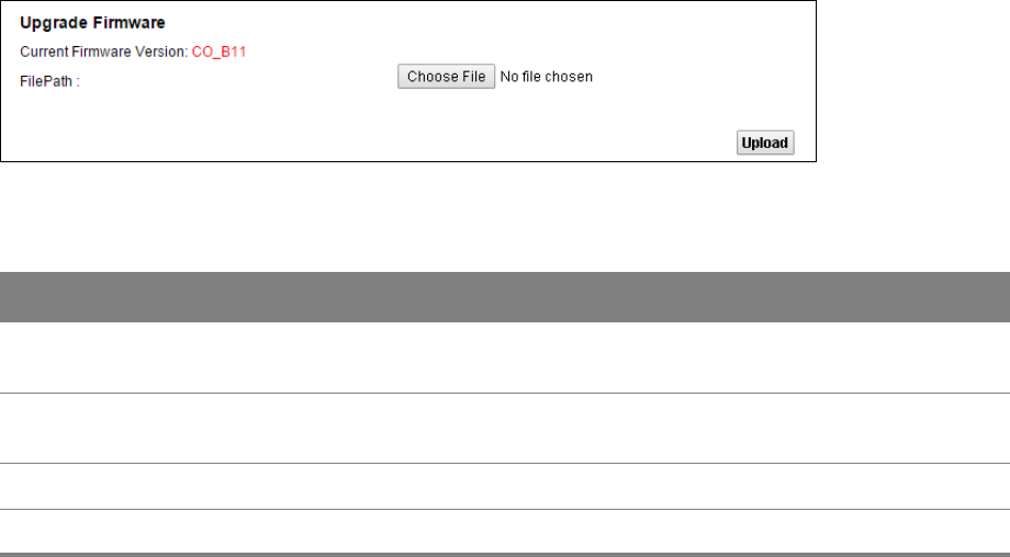
20
Chapter
Chapter 20 Firmware Upgrade 120
CHAPTER 20
Chapter 20 Firmware Upgrade
20.1 The Firmware Upgrade Screen
Click Maintenance > Firmware Upgrade to open the following screen. The upload process uses
HTTP (Hypertext Transfer Protocol) and may take up to three minutes. After a successful upload, the
system will reboot.
Only use firmware for your device’s specific model. Refer to the label on the bottom of
your Router.
Do NOT turn off the Router while firmware upload is in progress!
Figure 83 Maintenance > Firmware Upgrade
Table 73 Maintenance > Firmware Upgrade
LABEL DESCRIPTION
Upgrade
Firmware
Use these fields to upload firmware to the Router.
Current
Firmware Version
This is the present firmware version.
File Path Click Choose File and find the file you want to upload.
Upload Click this to begin the upload process. This process may take up to three minutes.
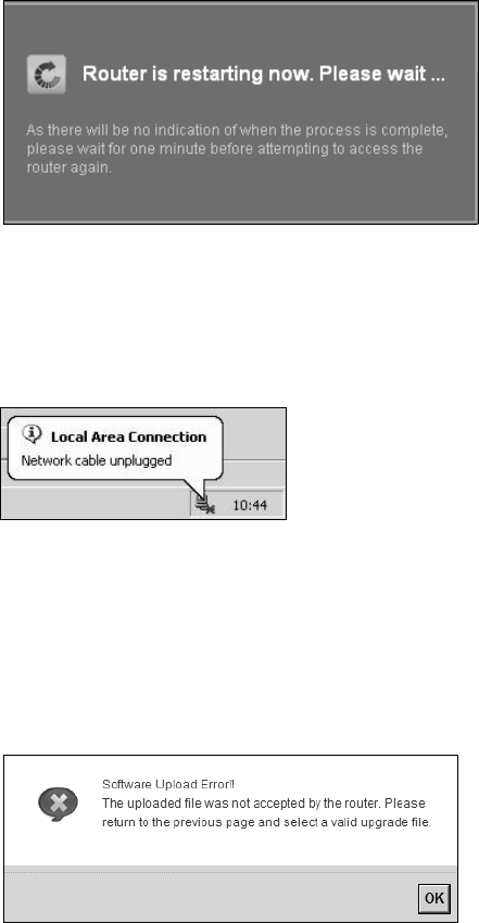
Chapter 20 Firmware Upgrade 121
After you see the firmware updating screen, wait a few minutes before logging into the Router
again.
Figure 84 Firmware Uploading
The Router automatically restarts in this time causing a temporary network disconnect. In some
operating systems, you may see the following icon on your desktop.
Figure 85 Network Temporarily Disconnected
After two minutes, log in again and check your new firmware version in the Status screen.
If the upload was not successful, an error screen will appear. Click OK to go back to the Firmware
Upgrade screen.
Figure 86 Error Message
21
Chapter
Chapter 21 Backup/Restore 122
CHAPTER 21
Chapter 21 Backup/Restore
21.1 The Backup/Restore Screen
Click Maintenance > Backup/Restore. Information related to factory defaults, backup
configuration, and restoring configuration appears in this screen, as shown next.
Figure 87 Maintenance > Backup/Restore
Backup Configuration
Backup Configuration allows you to back up (save) the Router’s current configuration to a file on
your computer. Once your Router is configured and functioning properly, it is highly recommended
that you back up your configuration file before making configuration changes. The backup
configuration file will be useful in case you need to return to your previous settings.
Click Backup to save the Router’s current configuration to your computer.
Chapter 21 Backup/Restore 123
Restore Configuration
Restore Configuration allows you to upload a new or previously saved configuration file from your
computer to your Router.
Table 74 Restore Configuration
LABEL DESCRIPTION
File Path Click Choose File and find the file you want to restore.
Upload Click this to begin the upload process.
Reset Click this to reset your device settings back to the factory default.
Do not turn off the Router while configuration file upload is in progress.
After the Router configuration has been restored successfully, the login screen appears. Login again
to restart the Router.
The Router automatically restarts in this time causing a temporary network disconnect. In some
operating systems, you may see the following icon on your desktop.
Figure 88 Network Temporarily Disconnected
If you restore the default configuration, you may need to change the IP address of your computer to
be in the same subnet as that of the default device IP address (192.168.1.1).
If the upload was not successful, an error screen will appear. Click OK to go back to the
Configuration screen.
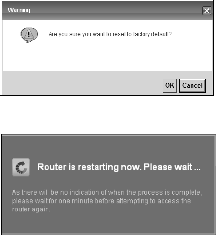
Chapter 21 Backup/Restore 124
Reset to Factory Defaults
Click the Reset button to clear all user-entered configuration information and return the Router to
its factory defaults. The following warning screen appears.
Figure 89 Reset Warning Message
Figure 90 Reset In Process Message
You can also press the Reset button on the back panel to reset the factory defaults of your Router.
Refer to Chapter 1 on page 7 for more information on the Reset button.
21.2 The Reboot Screen
System restart allows you to reboot the Router remotely without turning the power off. You may
need to do this if the Router hangs, for example.
Click Maintenance > Reboot. Click the Reboot button to have the Router reboot. This does not
affect the Router's configuration.
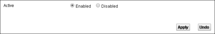
22
Chapter
Chapter 22 Remote Management 125
CHAPTER 22
Chapter 22 Remote Management
22.1 The General Screen
Remote management allows you to determine which services/protocols can access which Router
interface (if any) from which computers.
Click Maintenance > Remote MGMT to display the General screen. Select Enable to activate
remote management on the Router.
Figure 91 Maintenance > Remote MGMT > General
22.2 The WWW Screen
Use the WWW screen to specify how to connect to the Router from a web browser. Click
Maintenance > Remote MGMT > WWW screen.
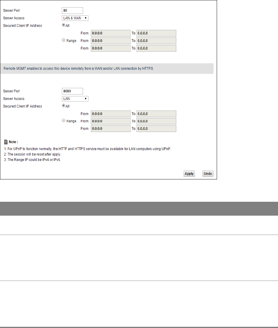
Chapter 22 Remote Management 126
Maintenance > Remote MGMT > WWW
Table 75 Maintenance > Remote MGMT > WWW
LABEL DESCRIPTION
Server Port This displays the service port number for accessing the Router using HTTP or HTTPS. If
the number is grayed out, it is not editable.
Server Access Select the interfaces through which a computer may access the Router using this
service.
Note: It is recommended if you are allowing WAN access even temporarily to change
the default password (in Maintenance > User Account). To allow access from
the WAN, you will need to configure a WAN to Router firewall rule.
Secured Client IP
Address
A secured client is a “trusted” computer that is allowed to communicate with the
Router using this service.
Select All to allow any computer to access the Router using this service.
Choose Range to just allow the computers with an IP address in the range that you
specify to access the Router using this service.
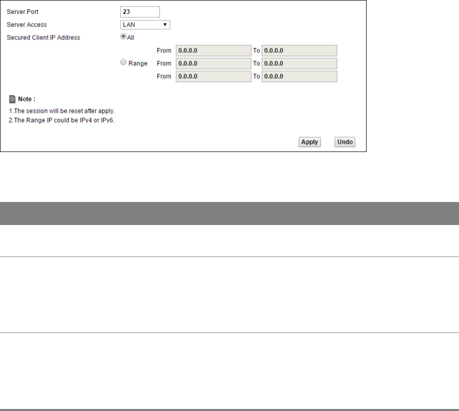
Chapter 22 Remote Management 127
22.3 Telnet Screen
You can use Telnet to access the Device’s command line interface. Specify which interfaces allow
Telnet access and from which IP address the access can come.
Click Maintenance > Remote MGMT > Telnet tab to display the screen as shown.
Figure 92 Maintenance > Remote MGMT > Telnet
Table 76 Maintenance > Remote MGMT > Telnet
LABEL DESCRIPTION
Server Port This displays the service port number for accessing the Router. If the number is grayed
out, it is not editable.
Server Access Select the interfaces through which a computer may access the Router using this
service.
Note: It is recommended if you are allowing WAN access even temporarily to change
the default password (in Maintenance > User Account). To allow access from
the WAN, you will need to configure a WAN to Router firewall rule.
Secured Client IP
Address
A secured client is a “trusted” computer that is allowed to communicate with the
Router using this service.
Select All to allow any computer to access the Router using this service.
Choose Range to just allow the computers with an IP address in the range that you
specify to access the Router using this service.
22.4 FTP Screen
You can use FTP (File Transfer Protocol) to upload and download the Router’s firmware and
configuration files. To use this feature, your computer must have an FTP client.
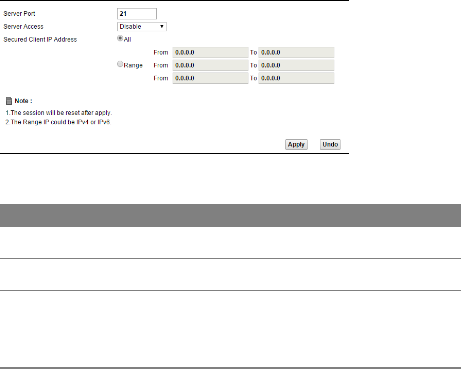
Chapter 22 Remote Management 128
Use this screen to specify which interfaces allow FTP access and from which IP address the access
can come. To change your Router’s FTP settings, click Maintenance > Remote MGMT > FTP. The
screen appears as shown.
Figure 93 Maintenance > Remote MGMT > FTP
Table 77 Maintenance > Remote MGMT > FTP
LABEL DESCRIPTION
Server Port This displays the service port number for accessing the Router. If the number is grayed
out, it is not editable.
Server Access Select the interfaces through which a computer may access the Router using this
service.
Secured Client IP
Address
A secured client is a “trusted” computer that is allowed to communicate with the
Router using this service.
Select All to allow any computer to access the Router using this service.
Choose Range to just allow the computers with an IP address in the range that you
specify to access the Router using this service.
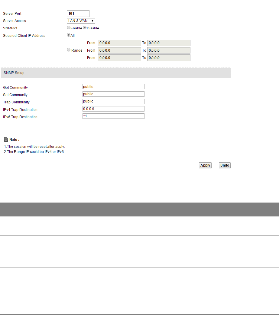
Chapter 22 Remote Management 129
22.5 SNMP Screen
To change your Router’s SNMP settings, click Maintenance > Remote MGMT > SNMP tab. The
screen appears as shown.
Figure 94 Maintenance > Remote MGMT > SNMP
Table 78 Maintenance > Remote MGMT > SNMP
LABEL DESCRIPTION
Server Port This displays the port the SNMP agent listens on. If the number is grayed out, it is not
editable.
Server Access Select the interfaces through which a computer may access the Router using this
service.
SNMPv3 Select Enable to activate the SNMPv3 feature.
Secured Client IP
Address
A secured client is a “trusted” computer that is allowed to access the SNMP agent on the
Router.
Select All to allow any computer to access the SNMP agent.
Choose Range to just allow the computers with an IP address in the range that you
specify to access the Router using this service.
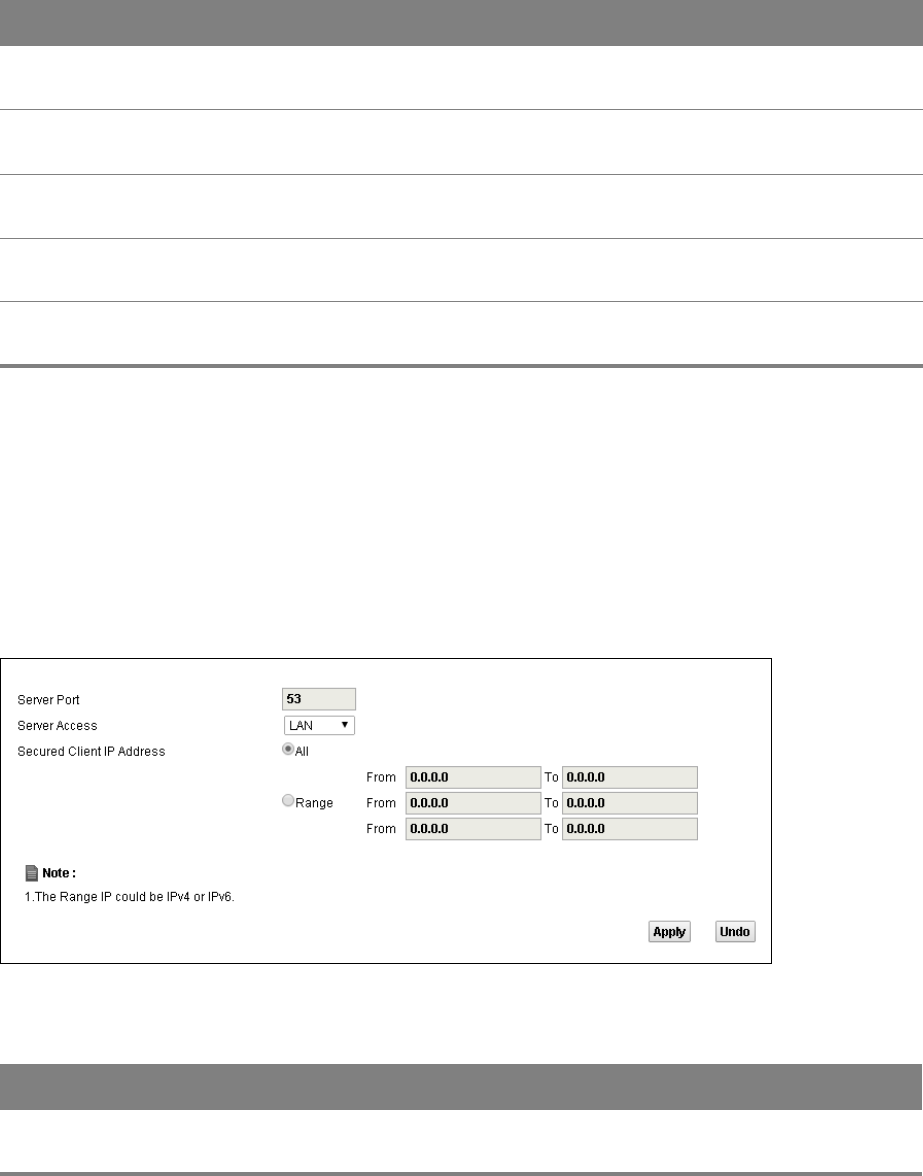
Chapter 22 Remote Management 130
22.6 DNS Screen
Use this screen to set from which IP address the Router will accept DNS queries and on which
interface it can send them your Router’s DNS settings. This feature is not available when the Router
is set to bridge mode. Click Maintenance > Remote MGMT > DNS to change your Router’s DNS
settings.
Figure 95 Maintenance > Remote MGMT > DNS
Get Community Enter the Get Community, which is the password for the incoming Get and GetNext
requests from the management station. The default is public and allows all requests.
Set Community Enter the Set community, which is the password for incoming Set requests from the
management station. The default is public and allows all requests.
Trap Community Type the trap community, which is the password sent with each trap to the SNMP
manager. The default is public and allows all requests.
IPv4 Trap
Destination
Type the IPv4 IP address of the station to send your SNMP traps to.
IPv6 Trap
Destination
Type the IPv6 IP address of the station to send your SNMP traps to.
Table 78 Maintenance > Remote MGMT > SNMP (continued)
LABEL DESCRIPTION
Table 79 Maintenance > Remote MGMT > DNS
LABEL DESCRIPTION
Server Port This displays the service port number for accessing the Router. If the number is grayed
out, it is not editable.

Chapter 22 Remote Management 131
22.7 ICMP Screen
To change your Router’s security settings, click Maintenance > Remote MGMT > ICMP. The screen
appears as shown.
Access Status Select the interfaces through which a computer may send DNS queries to the Router.
Secured Client IP
Address
A secured client is a “trusted” computer that is allowed to send DNS queries to the
Router.
Select All to allow any computer to send DNS queries to the Router.
Choose Range to just allow the computers with an IP address in the range that you
specify to send DNS queries to the Router.
Table 79 Maintenance > Remote MGMT > DNS (continued)
LABEL DESCRIPTION
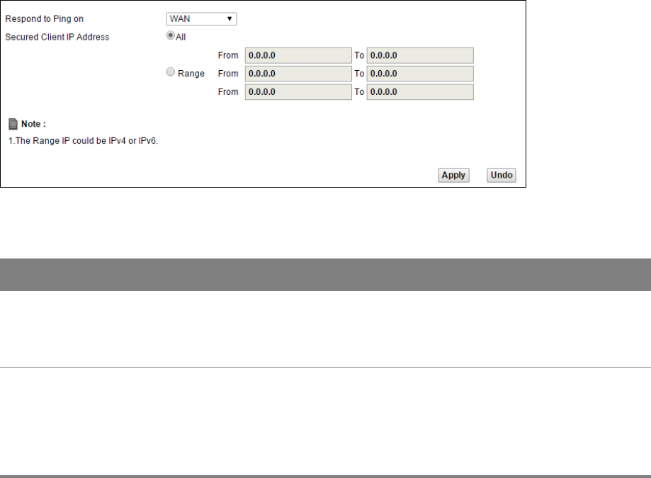
Chapter 22 Remote Management 132
If an outside user attempts to probe an unsupported port on your Router, an ICMP response packet
is automatically returned. This allows the outside user to know the Router exists. Your Router
supports anti-probing, which prevents the ICMP response packet from being sent. This keeps
outsiders from discovering your Router when unsupported ports are probed.
Figure 96 Maintenance > Remote MGMT > ICMP
Table 80 Maintenance > Remote MGMT > ICMP
LABEL DESCRIPTION
Respond to Ping
on
The Router will not respond to any incoming Ping requests when Disable is selected.
Select LAN to reply to incoming LAN Ping requests. Select WAN to reply to incoming
WAN Ping requests. Otherwise select LAN & WAN to reply to both incoming LAN and
WAN Ping requests.
Secured Client IP
Address
A secured client is a “trusted” computer that is allowed to send Ping requests to the
Router.
Select All to allow any computer to send Ping requests to the Router.
Choose Range to just allow the computers with an IP address in the range that you
specify to send Ping requests to the Router.
22.8 SSH/SCP/SFTP Screen
Secure Shell (SSH) is a secure communication protocol that combines authentication and data
encryption to provide secure encrypted communication between two hosts over an unsecured
network. The following file transfer methods use SSH:
•Secure Copy Protocol (SCP) is a secure way of transferring files between computers. It uses port
22.
•SSH File Transfer Protocol or Secure File Transfer Protocol (SFTP) is an old way of transferring
files between computers. It uses port 22.
You can use SSH to securely access the ’s command line interface. Specify which interfaces allow
SSH access and from which IP address the access can come.
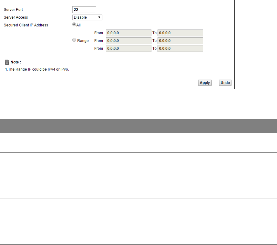
Chapter 22 Remote Management 133
Click Maintenance > Remote MGMT > SSH tab to display the screen as shown.
Figure 97 Maintenance > Remote MGMT > SSH
Table 81 Maintenance > Remote MGMT > SSH
LABEL DESCRIPTION
Server Port This displays the service port number for accessing the Router. If the number is grayed
out, it is not editable.
Server Access Select the interfaces through which a computer may access the Router using this
service.
Note: It is recommended if you are allowing WAN access even temporarily to change
the default password (in Maintenance > User Account). To allow access from
the WAN, you will need to configure a WAN to Router firewall rule.
Secured Client IP
Address
A secured client is a “trusted” computer that is allowed to communicate with the
Router using this service.
Select All to allow any computer to access the Router using this service.
Choose Range to just allow the computers with an IP address in the range that you
specify to access the Router using this service.
23
Chapter
Chapter 23 Troubleshooting 134
CHAPTER 23
Chapter 23 Troubleshooting
23.1 Overview
This chapter offers some suggestions to solve problems you might encounter. The potential
problems are divided into the following categories.
•Power, Hardware Connections, and LEDs
•Router Access and Login
•Internet Access
•Wireless Internet Access
•Phone Calls and VoIP
23.2 Power, Hardware Connections, and LEDs
The Router does not turn on. None of the LEDs turn on.
1Make sure the Router is turned on.
2Make sure you are using the power adaptor or cord included with the Router.
3Make sure the power adaptor or cord is connected to the Router and plugged in to an appropriate
power source. Make sure the power source is turned on.
4Turn the Router off and on.
5If the problem continues, contact the vendor.
One of the LEDs does not behave as expected.
1Make sure you understand the normal behavior of the LED. See Section 1.3 on page 9.
2Check the hardware connections. See Section 1.2 on page 7.
3Inspect your cables for damage. Contact the vendor to replace any damaged cables.
4Turn the Router off and on.
Chapter 23 Troubleshooting 135
5If the problem continues, contact the vendor.
23.3 Router Access and Login
I forgot the IP address for the Router.
1The default IP address is https://192.168.1.1:8000.
2If you changed the IP address and have forgotten it, you might get the IP address of the Router by
looking up the IP address of the default gateway for your computer. To do this in most Windows
computers, click Start > Run, enter cmd, and then enter ipconfig. The IP address of the Default
Gateway might be the IP address of the Router (it depends on the network), so enter this IP address
in your Internet browser.
3If this does not work, you have to reset the device to its factory defaults. See Section 1.2 on page 7.
I forgot the password.
1The default password is the first 6 digits of the Router’s MAC address. Please refer to the label
sticker at the device’s box for the MAC address.
2If you have changed the password but can’t remember it, you have to reset the device to its factory
defaults. See Section 1.2 on page 7.
I cannot see or access the Login screen in the web configurator.
1Make sure you are using the correct IP address.
• The default IP address is https://192.168.1.1:8000.
• If you changed the IP address (Section 5.1 on page 43), use the new IP address.
• If you changed the IP address and have forgotten it, see the troubleshooting suggestions for I
forgot the IP address for the Router.
2Check the hardware connections, and make sure the LEDs are behaving as expected. See Section 1.2
on page 7.
3Make sure your Internet browser does not block pop-up windows and has JavaScript and Java
enabled.
4Reset the device to its factory defaults, and try to access the Router with the default IP address. See
Section 1.2 on page 7.
5If the problem continues, contact the network administrator or vendor, or try one of the advanced
suggestions.
Chapter 23 Troubleshooting 136
Advanced Suggestions
• Try to access the Router using another service, such as Telnet. If you can access the Router, check
the remote management settings and firewall rules to find out why the Router does not respond
to HTTP.
• If your computer is connected wirelessly, use a computer that is connected to a LAN port.
I can see the Login screen, but I cannot log in to the Router.
1Make sure you have entered the user name and password correctly. These fields are case-sensitive,
so make sure [Caps Lock] is not on.
2You cannot log in to the web configurator while someone is using Telnet to access the Router. Log
out of the Router in the other session, or ask the person who is logged in to log out.
3Turn the Router off and on.
4If this does not work, you have to reset the device to its factory defaults. See Section 23.2 on page
134.
I cannot Telnet to the Router.
See the troubleshooting suggestions for I cannot see or access the Login screen in the web
configurator. Ignore the suggestions about your browser.
I cannot use FTP to upload / download the configuration file. / I cannot use FTP to upload
new firmware.
See the troubleshooting suggestions for I cannot see or access the Login screen in the web
configurator. Ignore the suggestions about your browser.
23.4 Internet Access
I cannot access the Internet.
1Check the hardware connections, and make sure the LEDs are behaving as expected. See Section 1.3
on page 9.
2Make sure you entered your ISP account information correctly. These fields are case-sensitive, so
make sure [Caps Lock] is not on.
3If you are trying to access the Internet wirelessly, make sure the wireless settings in the wireless
client are the same as the settings in the AP.
Chapter 23 Troubleshooting 137
4If you are trying to access the Internet wirelessly, make sure you have enabled the wireless LAN by
the WPS/WLAN button or the Network Setting > Wireless > General screen.
5Disconnect all the cables from your device, and follow the directions in Section 1.2 on page 7. again.
6If the problem continues, contact your ISP.
I cannot access the Internet anymore. I had access to the Internet (with the Router), but my
Internet connection is not available anymore.
1Check the hardware connections, and make sure the LEDs are behaving as expected. See Section 1.3
on page 9.
2Turn the Router off and on.
3If the problem continues, contact your ISP.
The Internet connection is slow or intermittent.
1There might be a lot of traffic on the network. Look at the LEDs, and check Section 1.3 on page 9. If
the Router is sending or receiving a lot of information, try closing some programs that use the
Internet, especially peer-to-peer applications.
2Turn the Router off and on.
3If the problem continues, contact the network administrator or vendor, or try one of the advanced
suggestions.
Advanced Suggestions
• Check the settings for QoS. If it is disabled, you might consider activating it. If it is enabled, you
might consider raising or lowering the priority for some applications.
23.5 Wireless Internet Access
What factors may cause intermittent or unstabled wireless connection? How can I solve
this problem?
The following factors may cause interference:
• Obstacles: walls, ceilings, furniture, and so on.
• Building Materials: metal doors, aluminum studs.
• Electrical devices: microwaves, monitors, electric motors, cordless phones, and other wireless
devices.
Chapter 23 Troubleshooting 138
To optimize the speed and quality of your wireless connection, you can:
• Move your wireless device closer to the AP if the signal strength is low.
• Reduce wireless interference that may be caused by other wireless networks or surrounding
wireless electronics such as cordless phones.
• Place the AP where there are minimum obstacles (such as walls and ceilings) between the AP and
the wireless client.
• Reduce the number of wireless clients connecting to the same AP simultaneously, or add
additional APs if necessary.
• Try closing some programs that use the Internet, especially peer-to-peer applications. If the
wireless client is sending or receiving a lot of information, it may have too many programs open
that use the Internet.
23.6 Phone Calls and VoIP
The telephone port won’t work or the telephone lacks a dial tone.
1Check the telephone connections and telephone wire.
I can access the Internet, but cannot make VoIP calls.
1The VOIP light should come on. Make sure that your telephone is connected to the VOIP port.
2You can also check the VoIP status in the System Info screen.
3If the VoIP settings are correct, use speed dial to make peer-to-peer calls. If you can make a call
using speed dial, there may be something wrong with the SIP server, contact your VoIP service
provider.

A
Appendix
Appendix A Safety Warnings 139
APPENDIX A
Appendix A Safety Warnings
•Do NOT use this product near water, for example, in a wet basement or near a swimming pool.
• Do NOT expose your device to dampness, dust or corrosive liquids.
• Do NOT store things on the device.
• Do NOT install, use, or service this device during a thunderstorm. There is a remote risk of electric shock from lightning.
• Connect ONLY suitable accessories to the device.
•Do NOT open the device or unit. Opening or removing covers can expose you to dangerous high voltage points or other risks. ONLY
qualified service personnel should service or disassemble this device. Please contact your vendor for further information.
•Make sure to connect the cables to the correct ports.
• Place connecting cables carefully so that no one will step on them or stumble over them.
• Always disconnect all cables from this device before servicing or disassembling.
•Use ONLY an appropriate power adaptor or cord for your device. Connect it to the right supply voltage (for example, 110V AC in North
America or 230V AC in Europe).
• Do NOT remove the plug and connect it to a power outlet by itself; always attach the plug to the power adaptor first before connecting it to
a power outlet.
• Do NOT allow anything to rest on the power adaptor or cord and do NOT place the product where anyone can walk on the power adaptor
or cord.
• Do NOT use the device if the power adaptor or cord is damaged as it might cause electrocution.
• If the power adaptor or cord is damaged, remove it from the device and the power source.
• Do NOT attempt to repair the power adaptor or cord. Contact your local vendor to order a new one.
•Do not use the device outside, and make sure all the connections are indoors. There is a remote risk of electric shock from lightning.
• Do NOT obstruct the device ventilation slots, as insufficient airflow may harm your device.
•Use only No. 26 AWG (American Wire Gauge) or larger telecommunication line cord.
• Antenna Warning! This device meets ETSI and FCC certification requirements when using the included antenna(s). Only use the included
antenna(s).
• If you wall mount your device, make sure that no electrical lines, gas or water pipes will be damaged.
• This product is for indoor use only (utilisation intérieure exclusivement).
Your product is marked with this symbol, which is known as the WEEE mark. WEEE stands for Waste Electronics and Electrical
Equipment. It means that used electrical and electronic products should not be mixed with general waste. Used electrical and
electronic equipment should be treated separately.
Federal Communication Commission Interference Statement
This device complies with Part 15 of the FCC Rules. Operation is subject to the following two conditions: (1) This device
may not cause harmful interference, and (2) this device must accept any interference received, including interference that
may cause undesired operation.
This equipment has been tested and found to comply with the limits for a Class B digital device, pursuant to Part 15 of the
FCC Rules. These limits are designed to provide reasonable protection against harmful interference in a residential
installation. This equipment generates, uses and can radiate radio frequency energy and, if not installed and used in
accordance with the instructions, may cause harmful interference to radio communications. However, there is no guarantee
that interference will not occur in a particular installation. If this equipment does cause harmful interference to radio or
television reception, which can be determined by turning the equipment off and on, the user is encouraged to try to correct
the interference by one of the following measures:
- Reorient or relocate the receiving antenna.
- Increase the separation between the equipment and receiver.
- Connect the equipment into an outlet on a circuit different from that
to which the receiver is connected.
- Consult the dealer or an experienced radio/TV technician for help.
FCC Caution: Any changes or modifications not expressly approved by the party responsible for compliance could void the
user's authority to operate this equipment.
This transmitter must not be co-located or operating in conjunction with any other antenna or transmitter.
Radiation Exposure Statement:
This equipment complies with FCC radiation exposure limits set forth for an uncontrolled environment. This equipment
should be installed and operated with minimum distance 20cm between the radiator & your body.